Valves, controls + systems âUnibox Eâ individual room temperature ...
Valves, controls + systems âUnibox Eâ individual room temperature ...
Valves, controls + systems âUnibox Eâ individual room temperature ...

You also want an ePaper? Increase the reach of your titles
YUMPU automatically turns print PDFs into web optimized ePapers that Google loves.
The Oventrop Quality Management<br />
System is certified to DIN-EN-ISO 9001<br />
<strong>Valves</strong>, <strong>controls</strong> + <strong>systems</strong><br />
“Unibox E” <strong>individual</strong> <strong>room</strong> <strong>temperature</strong> control<br />
and limitation of return <strong>temperature</strong><br />
in surface heating <strong>systems</strong><br />
Technical information<br />
Tender specification:<br />
Oventrop “Unibox E” for surface heating <strong>systems</strong><br />
– for <strong>temperature</strong> balance of floor or wall surfaces by limiting<br />
the return <strong>temperature</strong><br />
or<br />
– for <strong>individual</strong> <strong>room</strong> <strong>temperature</strong> control and limitation of<br />
return <strong>temperature</strong><br />
Max. working <strong>temperature</strong>: 100°C<br />
Max. working pressure: 10 bar<br />
Max. differential pressure: 1 bar<br />
Depth: 57 mm<br />
Installation set “Unibox E T” for <strong>individual</strong> <strong>room</strong> <strong>temperature</strong><br />
control with thermostatic valve (<strong>room</strong> <strong>temperature</strong> control) in<br />
surface heating <strong>systems</strong> consisting of:<br />
Wall box unit with presettable thermostatic valve, integrated<br />
deaeration, flushing valve and cover plate; with thermostat<br />
with ‘0’ setting; valve connection 3 ⁄4” for Oventrop compression<br />
fittings.<br />
Temperature range: 7-28°C (<strong>room</strong> <strong>temperature</strong>)<br />
0 = Complete shut off<br />
* = about 7°C, frost protection symbol<br />
1 = about 12°C<br />
}<br />
2 = about 16°C The minor graduations between the<br />
3 = about 20°C figures 2-4 represent a change of the<br />
4 = about 24°C <strong>room</strong> <strong>temperature</strong> of about 1°C.<br />
5 = about 28°C<br />
Item nos.: see table<br />
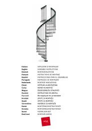
“Unibox E plus”, depth 57 mm<br />
Block or stud wall<br />
Wal box unit<br />
Thermostat<br />
Valve with presettable<br />
insert and integrated<br />
return <strong>temperature</strong> limiter<br />
Plaster<br />
Pipe conduit unit<br />
Edge isolating strip<br />
Protection pipe<br />
Screed<br />
Installation set “Unibox E RTL” for <strong>temperature</strong> limitation of<br />
heating surfaces with return <strong>temperature</strong> limiter consisting<br />
of:<br />
Wall box unit with integrated return <strong>temperature</strong> limiter, integrated<br />
deaeration, flushing valve and cover plate; valve<br />
connection 3 ⁄4” for Oventrop compression fittings.<br />
Temperature range: 20-40°C (return <strong>temperature</strong>)<br />
Graduation 0 – 40; the figures indicate the max. return <strong>temperature</strong>s<br />
in °C.<br />
Item nos.: see table<br />
Supply<br />
Return<br />
Installation set “Unibox E plus” for <strong>individual</strong> <strong>room</strong> <strong>temperature</strong><br />
control with thermostatic valve and for <strong>temperature</strong> limitation<br />
of heating surfaces with return <strong>temperature</strong> limiter<br />
consisting of:<br />
Wall box unit with presettable thermostatic valve, integrated<br />
return <strong>temperature</strong> limiter, integrated dearation, flushing<br />
valve and cover plate; with thermostat with ‘0’ setting; valve<br />
connection 3 ⁄4” for Oventrop compression fittings.<br />
Temperature range: 7-28 °C (<strong>room</strong> <strong>temperature</strong>)<br />
20-40°C (return <strong>temperature</strong>)<br />
Item nos.: see table<br />
Surface heating<br />
Installation sketch <strong>individual</strong> <strong>room</strong> <strong>temperature</strong> control<br />
and limitation of return <strong>temperature</strong><br />
“Unibox E T”<br />
“Unibox E RTL”<br />
“Unibox E plus”<br />
“Unibox E vario”<br />
Return <strong>temperature</strong> Cover Visible thermostat<br />
Thermostat<br />
Item no.<br />
limiter white chrome plated white chrome plated<br />
102 26 32 X X X<br />
102 26 42 X X X<br />
102 26 31 X X<br />
102 26 41 X X<br />
102 26 33 X X X X<br />
102 26 43 X X X X<br />
102 26 34 X X<br />
102 26 44 X X<br />
2006 Oventrop 1
Installation set “Unibox E vario” as basic model for <strong>temperature</strong><br />
limitation of heating surfaces with return <strong>temperature</strong><br />
limiter consisting of:<br />
Wall box unit with presettable thermostatic valve, integrated<br />
return <strong>temperature</strong> limiter, integrated deaeration, flushing<br />
valve and closed cover plate; valve connection 3 ⁄4” for Oventrop<br />
compression fittings.<br />
Temperature range: 20-40°C (return <strong>temperature</strong>)<br />
Item nos.: see table<br />
For <strong>room</strong> <strong>temperature</strong> control, the following items have to be<br />
ordered separately:<br />
– Thermostat with remote control “Uni LH”<br />
(see catalogue “Products”, page 13.23)<br />
or<br />
– Room thermostat and actuator<br />
(see catalogue “Products”, pages 1.12, 1.13)<br />
Pipe conduit unit, depth 100 cm, completely insulated,<br />
includes fixing material:<br />
Item no. 102 26 50<br />
Compression fittings (see catalogue “Products”, page 1.45)<br />
“Unibox E RTL”, depth 57 mm<br />
Block or stud wall<br />
Wall box unit<br />
Valve with integrated<br />
return <strong>temperature</strong> limiter<br />
Plaster<br />
Pipe conduit unit<br />
Edge isolating strip<br />
Protection pipe<br />
Screed<br />
Application:<br />
The different models of the “Unibox” are suitable for the<br />
operation of surface heating in a <strong>room</strong> with a heating surface<br />
up to 20 m 2 . They are designed for the connection of one<br />
heating circuit. Two circuits are required for larger heating<br />
surfaces. In this case, the pipes must be of the same length<br />
and have to be connected with the help of a T-piece or the<br />
“h” fitting, item no. 102 87 50 and the connection fitting, item<br />
no. 101 63 04 (see installation sketch on page 4) before entering<br />
the “Unibox”. The pressure loss can be reduced with the<br />
help of a larger sized return pipe. When installing heating<br />
pipes with an inner diameter of 12 mm, a pipe length of 100 m<br />
per heating circuit should not be exceeded. When laying the<br />
pipe, it is to be observed that the supply and the return pipe<br />
are alternately laid side by side. See e.g. spiral laying in the<br />
installation sketches. The examples of calculation mentioned<br />
below show some examples of laying.<br />
The “Unibox E RTL” allows the <strong>temperature</strong> limitation of<br />
heating surfaces. The <strong>room</strong> <strong>temperature</strong> is controlled via the<br />
radiators. Installation is carried out in combination with a<br />
radiator heating with a max. flow <strong>temperature</strong> of 70°C.<br />
The “Unibox E T” allows the control of the <strong>room</strong> <strong>temperature</strong><br />
via the surface heating. It is used in combination with a low<br />
<strong>temperature</strong> heating installation with a max. flow <strong>temperature</strong><br />
of 55°C.<br />
The “Unibox E plus” allows the <strong>individual</strong> <strong>room</strong> <strong>temperature</strong><br />
control with a thermostatic valve and the <strong>temperature</strong> limitation<br />
of the heating surfaces with a return <strong>temperature</strong> limiter.<br />
As for the “Unibox E RTL”, installation is carried out in combination<br />
with a radiator heating with a max. flow <strong>temperature</strong><br />
of 70°C.<br />
The “Unibox E vario” is used like a “Unibox E plus” when<br />
mounting a thermostat with remote control or a <strong>room</strong> thermostat<br />
and an actuator, and without these additions like a<br />
“Unibox E RTL”.<br />
57<br />
8 -23<br />
135<br />
60<br />
Supply<br />
Return<br />
Surface heating<br />
Installation sketch limitation of return <strong>temperature</strong><br />
1000<br />
155<br />
145<br />
135<br />
136 114<br />
48<br />
155<br />
8<br />
Dimensions “Unibox E RTL” and pipe conduit unit<br />
2 2006 Oventrop
1<br />
5<br />
Function:<br />
The “Unibox E RTL” serves to limit the return <strong>temperature</strong> of<br />
surface heating. The “Unibox E RTL” should be installed in<br />
such a position that the heating medium passes through the<br />
heating circuit first and then through the valve. On its way<br />
from the entry into the heating surface to the return <strong>temperature</strong><br />
limiter, the heating medium cools down.<br />
The flow is automatically controlled by a sensor element<br />
being in touch with the heating fluid. The return <strong>temperature</strong><br />
is set at the handwheel. The guidelines regarding heating up<br />
and initial operation are to be observed.<br />
The <strong>temperature</strong> of the surface heating can be corrected by<br />
turning the handwheel.<br />
Normally, the “Unibox E RTL” is operated in a <strong>room</strong> with an<br />
additional radiator. The surface heating covers the basic heat<br />
demand whereas the radiator takes on the control of the<br />
<strong>room</strong> <strong>temperature</strong>.<br />
The “Unibox E T” may only be operated with a max. flow<br />
<strong>temperature</strong> of the surface heating of 55°C (low <strong>temperature</strong><br />
heating). It offers a full <strong>individual</strong> <strong>room</strong> <strong>temperature</strong> control<br />
via the surface heating. It is recommended to install the “Unibox<br />
E T” in such a position that the heating medium passes<br />
through the heating circuit first and then through the valve.<br />
This way, the automatic thermostat <strong>controls</strong> the desired<br />
<strong>room</strong> <strong>temperature</strong> exactly. The hydronic balancing is carried<br />
out at the presettable valve insert.<br />
The “Unibox E T” can be operated without an additional<br />
radiator provided that the heat output capacity of the surface<br />
heating is sufficient.<br />
The “Unibox E plus” serves to control the <strong>temperature</strong> of<br />
<strong>individual</strong> <strong>room</strong>s via the surface heating and to limit the <strong>temperature</strong><br />
of the heating surface with the help of the return<br />
<strong>temperature</strong> limiter at the same time.<br />
The “Unibox E plus” is installed in the same position as the<br />
“Unibox E RTL”. The heating medium has to pass through<br />
the heating circuit of the surface heating first and then<br />
through the valve. On its way from the entry into the heating<br />
surface to the return <strong>temperature</strong> limiter, the heating medium<br />
cools down.<br />
The flow is automatically controlled by a sensor element<br />
being in touch with the heating fluid.<br />
The return <strong>temperature</strong> is set at the handwheel. The notes<br />
below regarding heating up and initial operation are to be observed.<br />
The surface <strong>temperature</strong> can be corrected by turning the<br />
handwheel.<br />
The automatic thermostat <strong>controls</strong> the desired <strong>room</strong> <strong>temperature</strong>.<br />
The hydronic balancing is carried out at the presettable<br />
valve insert. The “Unibox E plus” can be operated without an<br />
additional radiator, provided the heat output capacity of the<br />
surface heating is sufficient.<br />
The “Unibox E vario” offers the same function as the “Unibox<br />
E plus” when mounting a thermostat with remote control<br />
or a <strong>room</strong> thermostat and an actuator. The return <strong>temperature</strong><br />
is limited with the help of the integrated return <strong>temperature</strong><br />
limiter.<br />
For use as a “Unibox E vario”, return <strong>temperature</strong> control has<br />
to be added. This can be done by choosing one of the<br />
following options (to be ordered separately):<br />
1. With <strong>room</strong> thermostat and electrothermal actuator<br />
The electrothermal actuator is mounted on the vertical connection<br />
inside the “Unibox E vario”.<br />
To lead the connecting cable towards the <strong>room</strong> thermostat,<br />
drill a hole (Ø about 8 mm) at the marked point (sticker) on<br />
the outer wall of the wall unit.<br />
Electrical connections, especially in humid locations, must<br />
be carried out in accordance with the local Electricity Regulations<br />
and Standards.<br />
Temperature range: 5-30°C (<strong>room</strong> <strong>temperature</strong>)<br />
20-40°C (return <strong>temperature</strong>)<br />
2. With thermostat with remote control “Uni LH”<br />
The control is mounted on the vertical valve connection<br />
inside the “Unibox E vario”.<br />
The capillary towards the <strong>room</strong> <strong>temperature</strong> sensor can be<br />
led downwards out of the “Unibox E vario”. Laying through<br />
an empty pipe is advantageous.<br />
Temperature range: 7-28°C (<strong>room</strong> <strong>temperature</strong>)<br />
20-40°C (return <strong>temperature</strong>)<br />
Without these additions, control corresponds to the “Unibox<br />
E RTL”. Hydronic balance can additionally be carried out with<br />
the help of the presettable valve insert.<br />
Temperature range: 20-40°C (return <strong>temperature</strong>)<br />
“Unibox E T”, depth 57 mm<br />
Distributor/collector<br />
Supply<br />
Return<br />
Surface heating<br />
Block or stud wall<br />
Wall box unit<br />
Installation sketch <strong>individual</strong> <strong>room</strong> <strong>temperature</strong> control<br />
57<br />
8-23<br />
1000<br />
48<br />
190<br />
60<br />
155<br />
145<br />
Valve with<br />
presettable insert<br />
Thermostat<br />
Plaster<br />
Pipe conduit unit<br />
Edge isolating strop<br />
Protection pipe<br />
Screed<br />
Dimensions “Unibox E T”, “Unibox E plus”, “Unibox E vario”<br />
and pipe conduit unit<br />
2<br />
3<br />
4<br />
0<br />
135<br />
136 114<br />
8<br />
210<br />
2006 Oventrop 3
Installation and assembly:<br />
If the surface heating is installed as an underfloor heating,<br />
the lower edge of the “Unibox E” should be at least 20 cm<br />
above the finished floor, the front edge should be on a level<br />
with the finished wall. The thickness of plaster and tiles has<br />
to be observed. A comfortable operation is given if it is installed<br />
at the height of light switches.<br />
The thermostat should not be influenced by other heat<br />
sources.<br />
- Do not install near other heat sources, e.g. additional radiators.<br />
- Avoid direct sunlight to the thermostat.<br />
- Do not install at a location exposed to draught.<br />
The wall box unit is to be installed with the hole pointing<br />
downwards. Alignment and fixing are made by use of the enclosed<br />
elbows. They can be fixed at the side of the wall box<br />
unit in different positions.<br />
The wall box unit is sealed in the wall. The valve is protected<br />
by a cover made of corrugated cardboard.<br />
For a simple installation of the vertical pipework, place the<br />
pipe conduit unit, item no. 102 26 50, into the wall below the<br />
wall box unit, shorten if required. Later, the front of the pipe<br />
conduit unit will be under plaster.<br />
If required, lay an empty pipe for the cable between <strong>room</strong><br />
thermostat and actuator or respectively the capillary of the<br />
thermostat with remote control.<br />
If the “Unibox E vario” is equipped with an electric <strong>room</strong> thermostat<br />
and an actuator in bath<strong>room</strong>s, electrical connections<br />
must be carried out in accordance with the local Electricity<br />
Regulations and Standards.<br />
When designing the floor as a surface heating, the construction<br />
e.g. regarding thermal and sound insulation, has to comply<br />
with the valid rules, standards and regulations.<br />
When installing the pipework, the correct sequence has to be<br />
observed to ensure a perfect function of the “Unibox E”:<br />
- Provide derivation from the supply pipe of the two pipe<br />
heating system.<br />
- Laying of the heating circuit. When installing a “Unibox E”<br />
with limitation of return <strong>temperature</strong>, the pipes have to be<br />
laid spiral patterned (see installation sketch). A constant<br />
<strong>temperature</strong> distribution is achieved.<br />
- Connection of the pipework to the “Unibox E”, marked direction<br />
of flow has to be observed. Valve always behind<br />
the heating circuit. Remove the protection cover of the<br />
“Unibox” as well as the front cover of the pipe conduit<br />
unit.<br />
- Installation of the connecting pipe to the return pipe of the<br />
two pipe heating system.<br />
The surface heating can be installed with any standard pipe<br />
material.<br />
The Oventrop programme includes suitable compression fittings.<br />
The corresponding installation instructions are to be<br />
observed. Insert the copper pipe a maximum of 5 mm<br />
deeper than the fitting. An open ring spanner 30 mm, e.g.<br />
Oventrop item no. 140 10 91, is recommended to tighten the<br />
fittings.<br />
The installation is filled and bled, e.g. at the valve. Then carry<br />
out leakage test and remount protection cap of the valve and<br />
front cover of the pipe conduit unit.<br />
“Unibox E vario” with <strong>room</strong> thermostat and actuator<br />
Supply<br />
Return<br />
Surface heating<br />
Block or stud wall<br />
Room thermostat<br />
Empty pipe with cable<br />
Actuator<br />
Valve with presettable<br />
insert and integrated<br />
return <strong>temperature</strong> limiter<br />
Plaster<br />
Pipe conduit unit<br />
Edge isolating strip<br />
Protection pipe<br />
Screed<br />
Installation sketch “Unibox E vario” wit <strong>room</strong> thermostat<br />
and actuator<br />
Block or stud wall<br />
Thermostat with<br />
remote control<br />
Empty pipe with capillary<br />
Valve with presettable<br />
insert and integrated<br />
return <strong>temperature</strong> limiter<br />
Plaster<br />
Pipe conduit unit<br />
Edge isolating strip<br />
Protection pipe<br />
Screed<br />
“Unibox E vario” with thermostat with remote control “Uni LH”<br />
Supply<br />
Return<br />
Surface heating<br />
Installation sketch “Unibox E vario” with thermostat with<br />
remote control “Uni LH”<br />
4 2006 Oventrop
Important note for heating up:<br />
After all plastering is finished, a heating screed complying<br />
with standards has to be laid. The concrete and anhydrite<br />
screed have to be heated up according to EN 1264-4 or<br />
ZVSHK documentations FBH-D1 to D4.<br />
Start heating up:<br />
– at the earliest 21 days after having laid the concrete floor<br />
– at the earliest 7 days after having laid the anhydrite concrete<br />
floor<br />
Heat up slowly!<br />
3 days with a flow <strong>temperature</strong> of about 25°C and then<br />
4 days with a flow <strong>temperature</strong> of about 55°C<br />
Flow <strong>temperature</strong> is only controlled by the boiler control.<br />
Open valve of the “Unibox E”: Turn the handwheel of the return<br />
<strong>temperature</strong> limiter to the maximum position and/or<br />
open presettable valve insert by turning the protection cap<br />
about 1 turn.<br />
Instructions of the concrete manufacturers are to be observed.<br />
After having completed all building work, the protection cover<br />
is removed.<br />
For the “Unibox E T” and the “Unibox E plus”, mount the remote<br />
control on the right hand valve insert, lead the capillary<br />
downwards and fit the enclosed valve insulation inside the<br />
box. The capillary may not be kinked or damaged.<br />
For the “Unibox E vario”, mount the thermostat “Uni LH” with<br />
remote control or an actuator on the right hand valve insert.<br />
Mount and adjust the white or chrome plated cover (front<br />
cover).<br />
Important note for putting the system into operation:<br />
The recommended <strong>temperature</strong> range of the return <strong>temperature</strong><br />
limiter is between 25°C and 40°C.<br />
The maximum permissible concrete <strong>temperature</strong> near the<br />
heating pipes may not be exceeded:<br />
– 55°C for concrete and anhydrite concrete<br />
– 45°C for mastic asphalt concrete<br />
– or according to the instructions of the concrete manufacturer<br />
2006 Oventrop 5
Examples of calculation:<br />
“Unibox E RTL” or “Unibox E plus”<br />
Application: Bath<strong>room</strong><br />
Pipe material: Composition pipe “Copipe” 16 x 2 mm<br />
Room <strong>temperature</strong>: 24°C<br />
Room <strong>temperature</strong> of the <strong>room</strong> below: 20°C<br />
Max. heating surface <strong>temperature</strong>: 33°C<br />
R λ = 0.02 m 2 K/W (tiles)<br />
Set return <strong>temperature</strong>: 35°C<br />
Laying Pipe Heating Spec. Pressure Flow<br />
distance length surface heat loss rate<br />
output pipework<br />
[mm] [m] [m 2 ] [W/m 2 ] [mbar] [l/s]<br />
175 100 17,5 93 155 0.0197<br />
150 180 12 76 175 0.0261<br />
150 100 15 76 137 0.0325<br />
225 180 18 63 110 0.0322<br />
225 189 20 60 115 0.0314<br />
300 167 20 51 181 0.0300<br />
“Unibox E T”<br />
Application: Living area<br />
Pipe material: Composition pipe “Copipe” 16 x 2 mm<br />
Room <strong>temperature</strong>: 20°C<br />
Room <strong>temperature</strong> of the <strong>room</strong> below: 20°C<br />
Max. heating surface <strong>temperature</strong>: 29°C<br />
R λ = 0.1 m 2 K/W (parquet)<br />
Flow <strong>temperature</strong>: 50°C<br />
Laying Pipe Heating Spec. Pressure Flow<br />
distance length surface heat loss rate<br />
output pipework<br />
[mm] [m] [m 2 ] [W/m 2 ] [mbar] [l/s]<br />
175 100 17,5 100 183 0.0247<br />
150 180 12 185 113 0.0328<br />
150 100 15 180 118 0.0300<br />
225 180 18 170 114 0.0331<br />
225 189 20 167 108 0.0303<br />
300 167 20 161 104 0.0342<br />
For the design of the installation it has to be observed that<br />
the pressure loss of the pipe and the valve may not exceed a<br />
sum of 300 mbar.<br />
The models<br />
– “Unibox E plus”<br />
– “Unibox E T”<br />
– “Unibox E RTL” (if <strong>temperature</strong> limitation of a heating surface<br />
and the thermostatically controlled radiator are located<br />
in the same <strong>room</strong>)<br />
comply with the Decree for Energy Saving valid since February<br />
2002 (EnEV § 12).<br />
Advantages:<br />
– simple installation<br />
– best possible control characteristics<br />
– stylish unit (flat model)<br />
– comfortable height for use of control<br />
– smart optical integration into the wall<br />
– cover plate in modern colours white RAL 9010 and<br />
chrome plated<br />
– rotating plastic cover plate which can be fitted without<br />
screws<br />
– the strong pipe conduit unit also serves as insulation<br />
– suitable for the connection to any standard pipes for surface<br />
heating <strong>systems</strong><br />
– no auxiliary energy (current) required<br />
– economical installation of a surface heating<br />
– higher living comfort<br />
– optimum control even of combined installations (surface<br />
heating/radiator connection)<br />
– integrated deaeration<br />
Performance data “Unibox E T” and “Unibox E plus”<br />
Presetting 1 2 3 4 5 6<br />
kv value at<br />
1K P-deviation<br />
0.043 0.11 0.19 0.24 0.26 0.28<br />
kv value at<br />
1,5K P-deviation<br />
0.043 0.11 0.23 0.33 0.39 0.42<br />
kv value at<br />
2K P-deviation<br />
0.043 0.12 0.25 0.37 0.47 0.52<br />
kvs 0.75<br />
Subject to technical modification without notice.<br />
Product range 13<br />
ti 152-1/20/MW<br />
Gedruckt auf chlorfrei<br />
Edition 2006<br />
gebleichtem Papier.<br />
Pressure loss chart for “Unibox E RTL”<br />
P-deviation<br />
Pressure loss ∆p [mbar]<br />
Pressure loss chart “Unibox E T” at 2 K P-deviation and<br />
“Unibox E plus”, RTL completely opened<br />
Presetting<br />
Pressure loss ∆p [mbar]<br />
at 1 K P-deviation<br />
Presetting<br />
Pressure loss ∆p [mbar]<br />
OVENTROP UK LTD.<br />
Unit I – The Loddon Centre<br />
Wade Road<br />
Basingstoke, Hampshire RG24 8FL<br />
Great Britain<br />
Telephone (01256) 330441<br />
Telefax (Sales) (01256) 330525<br />
Telefax (General) (01256) 470970<br />
E-Mail<br />
sales@oventrop.co.uk<br />
Flow rate V<br />
·<br />
[l/s]<br />
Flow rate V<br />
·<br />
[l/s]<br />
Flow rate V<br />
·<br />
[l/s]<br />
Pressure loss ∆p [Pascal]<br />
Pressure loss ∆p [Pascal]<br />
Pressure loss ∆p [Pascal]<br />
F. W. OVENTROP GmbH & Co. KG<br />
Paul-Oventrop-Straße 1<br />
D-59939 Olsberg<br />
Germany<br />
Telephone (02962) 82-0<br />
Telefax (02962) 82-450<br />
E-Mail mail@oventrop.de<br />
Internet www.oventrop.de<br />
6 2006 Oventrop