TTP-244 Plus Bar Code Printer Service Manual - TSC
TTP-244 Plus Bar Code Printer Service Manual - TSC
TTP-244 Plus Bar Code Printer Service Manual - TSC

Create successful ePaper yourself
Turn your PDF publications into a flip-book with our unique Google optimized e-Paper software.
<strong>TTP</strong>-<strong>244</strong> <strong>Plus</strong><br />
THERMAL TRANSFER BAR CODE PRINTER<br />
<strong>Service</strong><br />
<strong>Manual</strong><br />
<strong>TTP</strong>/TDP <strong>244</strong>/342
<strong>TTP</strong>-<strong>244</strong> <strong>Plus</strong> <strong>Bar</strong> <strong>Code</strong><br />
<strong>Printer</strong> <strong>Service</strong> <strong>Manual</strong><br />
Table of Contents<br />
1. FUNDAMENTALS ABOUT THE SYSTEM .................................................................. 1<br />
1.1 Features of the <strong>TTP</strong>/TDP-<strong>244</strong> <strong>Plus</strong> ............................................................................ 1<br />
1.2 Model Naming Syntax ............................................................................................ 1<br />
1.3 Overview .................................................................................................................... 2<br />
1.3.1 Front View ........................................................................................................... 2<br />
1.3.2 Rear View ........................................................................................................... 3<br />
1.4 Basic Specifications .................................................................................................... 4<br />
1.5 Effective Print Area ..................................................................................................... 5<br />
1.6 Available <strong>Bar</strong> <strong>Code</strong>s ................................................................................................... 5<br />
1.7 Various Sensors ......................................................................................................... 6<br />
2. SUPPLY SPECIFICATIONS ............................................................................................. 8<br />
2.1 Types of Paper ........................................................................................................... 8<br />
2.2 Specifications ............................................................................................................. 8<br />
2.3 Ribbon Sizes and Shapes ........................................................................................ 10<br />
3. ELECTRONICS .............................................................................................................. 11<br />
3.1 Summary of Board Connectors ................................................................................ 11<br />
3.2 Pin Configuration ...................................................................................................... 13<br />
4. MECHANISM .................................................................................................................. 15<br />
4.1 Mainboard Replacement ........................................................................................... 15<br />
4.2 DC Motor Replacement ............................................................................................ 17<br />
4.3 Print Head Replacement .......................................................................................... 21<br />
4.4 Ribbon Rewind Spindle Encoder Replacement ........................................................ 23<br />
4.5 Felt Fabric Replacement .......................................................................................... 24<br />
4.6 Stepping Motor Replacement ................................................................................... 26<br />
4.7 Black Mark Sensor / Gap Sensor (Receiver) Replacement ...................................... 27<br />
4.8 Ribbon Sensor (Receiver) Replacement ................................................................... 28<br />
4.9 Ribbon Sensor (Transmitter) / Gap Sensor (Transmitter) Replacement ................... 30<br />
i
<strong>TTP</strong>-<strong>244</strong> <strong>Plus</strong> <strong>Bar</strong> <strong>Code</strong><br />
<strong>Printer</strong> <strong>Service</strong> <strong>Manual</strong><br />
4.10 Platen Replacement ............................................................................................... 31<br />
5. TROUBLE SHOOTING ................................................................................................... 33<br />
5.1 Trouble Shooting ...................................................................................................... 33<br />
5.2 Calibrate the Gap Register ....................................................................................... 34<br />
5.3 Self-test .................................................................................................................... 34<br />
5.4 Ram Clear ................................................................................................................ 34<br />
5.5 Diagnosis Operation Procedure ................................................................................ 34<br />
5.6 Testing Sensors ....................................................................................................... 35<br />
UPDATE HISTORY ............................................................................................................ 36<br />
ii
<strong>TTP</strong>-<strong>244</strong> <strong>Plus</strong> <strong>Bar</strong> <strong>Code</strong><br />
<strong>Printer</strong> <strong>Service</strong> <strong>Manual</strong><br />
1. FUNDAMENTALS ABOUT THE SYSTEM<br />
1.1 Features of the <strong>TTP</strong>/TDP-<strong>244</strong> <strong>Plus</strong><br />
1. <strong>TTP</strong>-<strong>244</strong> <strong>Plus</strong> bar code printer prints bar codes, characters, logos, on various types of labels<br />
and tickets by direct thermal or thermal transfer printing.<br />
2 <strong>TTP</strong>-<strong>244</strong> <strong>Plus</strong> adopts a “BASIC-like” high level programming language to help users<br />
programme the desired label forms with ease.<br />
3. <strong>TTP</strong>-<strong>244</strong> <strong>Plus</strong> bar code printer can be connected to a personal computer or an optional LCD<br />
keyboard to execute the programs downloaded in the printer’s memory. The printer is<br />
equipped with the following standard devices:gap transmissive sensor, black mark reflective<br />
sensor and ribbon end sensor.<br />
4. <strong>TTP</strong>-<strong>244</strong> <strong>Plus</strong> bar code printer provides a selection of optional features, including portable LCD<br />
keyboard, etc.<br />
1.2 Model Naming Syntax<br />
T T P – 2 4 4 <strong>Plus</strong><br />
(1) (2) (3) (4)<br />
(1) Print method:<br />
<strong>TTP</strong> – Thermal Transfer Printing<br />
TDP – Thermal Direct Printing<br />
(2) Resolution of print head (DPI)<br />
(3) Maximum print width (Inch)<br />
(4) Maximum print speed (Inch/Sec)<br />
1
<strong>TTP</strong>-<strong>244</strong> <strong>Plus</strong> <strong>Bar</strong> <strong>Code</strong><br />
<strong>Printer</strong> <strong>Service</strong> <strong>Manual</strong><br />
1.3 Overview<br />
1.3.1 Front View<br />
PAUSE Button<br />
PWR., ON-LINE<br />
and ERR.<br />
Indicators<br />
Top Cover<br />
FEED Button<br />
Label Dispense<br />
Opening<br />
Cover Release Button<br />
2
<strong>TTP</strong>-<strong>244</strong> <strong>Plus</strong> <strong>Bar</strong> <strong>Code</strong><br />
<strong>Printer</strong> <strong>Service</strong> <strong>Manual</strong><br />
1.3.2 Rear View<br />
Label Insert<br />
Opening (for use<br />
with external<br />
labels)<br />
Power On/Off<br />
Switch<br />
Power Supply<br />
Connector<br />
RS-232 Interface<br />
Connector<br />
USB Interface<br />
Connector<br />
Centronics Interface<br />
Connector (Option)<br />
3
<strong>TTP</strong>-<strong>244</strong> <strong>Plus</strong> <strong>Bar</strong> <strong>Code</strong><br />
<strong>Printer</strong> <strong>Service</strong> <strong>Manual</strong><br />
1.4 Basic Specifications<br />
• Thermal transfer and direct thermal printing<br />
• High dot density printing (203 dots/inch)<br />
• Selectable print speeds at 2.0”, 3.0” or 4.0” per second<br />
• Supports RS-232 and USB interface<br />
• Maximum media width up to 4.49” (114 mm)<br />
• Adjustable label edge guide<br />
• International character sets<br />
• Print area is 4.09”W x 40”L (without any file downloaded in the printer memory)<br />
• User selectable bar code ratios and heights<br />
• Prints on labels or tickets<br />
• Equipped with black mark sensor<br />
• Label stock and thermal transfer ribbon are easy to install<br />
• Internal label print counter<br />
• Self test and hex dump mode<br />
• Downloadable fonts from label design software<br />
Electronics/Communication Specifications<br />
• Electrical<br />
DC Motor: DC24V<br />
Memory:<br />
─DRAM: 8 Mb<br />
─Flash: 2 Mb<br />
Adapter 100~240VAC10%, 50~60Hz<br />
Regulations: FCC Class A, CE Class A, C-Tick Class A, TÜ V/GS, CCC<br />
• Communications Interface:<br />
* RS-232/USB<br />
* RS-232/Centronics (factory option)<br />
4
<strong>TTP</strong>-<strong>244</strong> <strong>Plus</strong> <strong>Bar</strong> <strong>Code</strong><br />
<strong>Printer</strong> <strong>Service</strong> <strong>Manual</strong><br />
• RS-232 Interface Pin Configuration:<br />
Host Function 9 Pin 25 Pin 9 Pin <strong>Printer</strong> Function<br />
1 +5V<br />
RxD 2 3 2 TxD<br />
TxD 3 2 3 RxD<br />
DTR 4 20 4 DSR<br />
GND 5 7 5 GND<br />
DSR 6 6 6 RDY<br />
RTS 7 4 7 N/C<br />
CTS 8 5 8 RDY<br />
9 +5V<br />
1.5 Effective Print Area<br />
1.6 Available <strong>Bar</strong> <strong>Code</strong>s<br />
1D bar code:<br />
• <strong>Code</strong> 39<br />
• <strong>Code</strong> 93<br />
• <strong>Code</strong> 128 UCC<br />
• <strong>Code</strong> 128, Subsets A, B, and C<br />
Label/Ticket Length 12mm~2286mm<br />
Effective Print<br />
10mm~2284mm<br />
Length<br />
Label/Ticket Width 25mm~103mm<br />
Effective Print Width 23mm~101mm<br />
No Print Area 1mm<br />
5
<strong>TTP</strong>-<strong>244</strong> <strong>Plus</strong> <strong>Bar</strong> <strong>Code</strong><br />
<strong>Printer</strong> <strong>Service</strong> <strong>Manual</strong><br />
• Codabar<br />
• Interleaved 2 of 5<br />
• EAN-8, EAN-13, EAN-128<br />
• UPC-A, UPC-E<br />
• EAN and UPC with 2 or 5 digits add-on<br />
• MSI<br />
• Postnet<br />
• Plessey<br />
• China POST<br />
2D bar codes:<br />
• Maxicode<br />
• DataMatrix<br />
• PDF-417<br />
• QR code<br />
1.7 Various Sensors<br />
Feed Gap Sensor<br />
The feed gap sensor detects a label gap to locate the starting print position of the next<br />
label. The sensor is mounted 4 mm off the center line of the main mechanism.<br />
In case of Label<br />
Black Mark Sensor<br />
The black mark sensor locates the position of label by emitting infrared rays onto the<br />
black mark at the back of the ticket. The sensor is mounted 5.75 mm off the center line<br />
of the ticket roll width on the mechanism.<br />
6
<strong>TTP</strong>-<strong>244</strong> <strong>Plus</strong> <strong>Bar</strong> <strong>Code</strong><br />
<strong>Printer</strong> <strong>Service</strong> <strong>Manual</strong><br />
In case of Ticket<br />
The default sensor position is (1) as shown on the figure below. To change to the (2)<br />
position, the customer should notify the manufacturer in advance. There can be only<br />
one position for the sensor. Once the sensor position is agreed upon, it can not be<br />
changed afterwards.<br />
Ribbon End Sensor<br />
The sensor detects the end portion of the ribbon. The ribbon end must be transparent.<br />
Label End Sensor<br />
The sensor detects the end portion of the label.<br />
Ribbon encoder<br />
The encoder is used to detect if the ribbon is broken.<br />
7
<strong>TTP</strong>-<strong>244</strong> <strong>Plus</strong> <strong>Bar</strong> <strong>Code</strong><br />
<strong>Printer</strong> <strong>Service</strong> <strong>Manual</strong><br />
2. SUPPLY SPECIFICATIONS<br />
2.1 Types of Paper<br />
Two types of media are available for <strong>TTP</strong>-<strong>244</strong> <strong>Plus</strong>: label and ticket.<br />
In <strong>TTP</strong>-<strong>244</strong> <strong>Plus</strong>, there are two types of sensors for paper: gap sensor and black mark<br />
sensor.<br />
Label and ticket can be further classified into direct thermal type or thermal transfer type.<br />
2.2 Specifications<br />
Items<br />
Max.114mm<br />
Paper Width<br />
Min. 25.4mm<br />
Length (Pitch) 10~1016mm<br />
Paper<br />
0.25 mm<br />
Thickness<br />
Paper Weight Max 240 g/m 2<br />
Max. Roll<br />
Diameter<br />
(1” core)<br />
Label<br />
Inner roll diameter. Max 4.3” (110mm)<br />
External roll diameter. Max 8.4”<br />
(214mm)<br />
Roll Up Method Print surface wound outside as<br />
standard<br />
Paper Core ID. 25.7±0.3mm<br />
Note:<br />
(1). The width and thickness quoted above are said of the label plus its backing paper.<br />
(2). Likewise, the approval of label entails that of its backing paper.<br />
(3). Paper shape is as shown on next page:<br />
8
<strong>TTP</strong>-<strong>244</strong> <strong>Plus</strong> <strong>Bar</strong> <strong>Code</strong><br />
<strong>Printer</strong> <strong>Service</strong> <strong>Manual</strong><br />
9
<strong>TTP</strong>-<strong>244</strong> <strong>Plus</strong> <strong>Bar</strong> <strong>Code</strong><br />
<strong>Printer</strong> <strong>Service</strong> <strong>Manual</strong><br />
2.3 Ribbon Sizes and Shapes<br />
Item<br />
Ribbon shape<br />
Ribbon width<br />
Ribbon winding width<br />
Leading tape<br />
End tape<br />
Max. ribbon OD.<br />
Winding method<br />
Specifications<br />
Spool type<br />
Max. 110mm<br />
Min. 40mm<br />
Max. 110mm<br />
Min. 40mm<br />
Polyester film, 3355mm long<br />
Polyester film (transparent), 2505mm<br />
long<br />
67mm<br />
Ink surface to be wound outside<br />
Note: The maximum length of ribbon depends on its thickness and core outside diameter.<br />
The formula below defines the correlation between ribbon roll length and ribbon core<br />
diameter.<br />
2 2<br />
(D d ) <br />
L =<br />
, where<br />
4t<br />
L = Ribbon length<br />
D = Max. roll diameter<br />
d = Ribbon core outside diameter<br />
t = Ribbon thickness<br />
10
<strong>TTP</strong>-<strong>244</strong> <strong>Plus</strong> <strong>Bar</strong> <strong>Code</strong><br />
<strong>Printer</strong> <strong>Service</strong> <strong>Manual</strong><br />
3. ELECTRONICS<br />
3.1 Summary of Board Connectors<br />
Main board<br />
1 2 3<br />
4<br />
5<br />
6<br />
7<br />
8<br />
14<br />
9<br />
10 11<br />
12<br />
13<br />
Connector Description Remark<br />
1 Ribbon sensor connector JP18<br />
Black mark sensor connector<br />
JP46<br />
2<br />
Pin Description Voltage<br />
1 Power 5V<br />
2<br />
Black mark No paper or black mark : 3.1~3.2V<br />
sensor receiver Detect paper: 0~0.3V<br />
3 GND 0V<br />
11
<strong>TTP</strong>-<strong>244</strong> <strong>Plus</strong> <strong>Bar</strong> <strong>Code</strong><br />
<strong>Printer</strong> <strong>Service</strong> <strong>Manual</strong><br />
Gap sensor connector<br />
JP53<br />
3<br />
Pin Description Voltage<br />
1 GND 0V<br />
2 Gap sensor emitter<br />
Emitter on : 0.7~1.8V<br />
Emitter off: 2.4~2.7V<br />
3 Power 5V<br />
4 GND 0V<br />
5 Gap sensor receiver<br />
No paper or gap: 3.1~3.2V<br />
Detect paper: 0~0.3V<br />
6 Power 5V<br />
4 Ribbon encoder sensor & DC motor connector JP37<br />
5 Stepping motor connector JP14<br />
6 Print head connector JP42<br />
7 SD memory card module connector JP44<br />
8 Micro processor U2<br />
9 Power switch SW2<br />
10 Power supply output (24V DC) connector B3<br />
11 RS-232C connector JP7<br />
12 Centronics port connector (Option) JP4<br />
13 USB connector JP9<br />
Push button connector<br />
JP52<br />
14<br />
Pin Description Voltage<br />
1 LED green (PWR)<br />
LED light on: 2.0~2.2V<br />
LED light off: 0~0.3V<br />
2 LED green (ONLINE)<br />
LED light on: 2.0~2.2V<br />
LED light off: 0~0.3V<br />
3 LED red (ERR)<br />
LED light on : 2.0~2.2V<br />
LED light off: 0~0.3V<br />
4 Pause switch<br />
0V: Push key<br />
3.3V: Stand-by<br />
5 Feed switch<br />
0V: Push key<br />
3.3V: Stand-by<br />
6 GND 0V<br />
12
<strong>TTP</strong>-<strong>244</strong> <strong>Plus</strong> <strong>Bar</strong> <strong>Code</strong><br />
<strong>Printer</strong> <strong>Service</strong> <strong>Manual</strong><br />
3.2 Pin Configuration<br />
RS-232C<br />
USB<br />
PIN CONFIGURATION<br />
1 +5 V<br />
2 TXD<br />
3 RXD<br />
4 CTS<br />
5 GND<br />
6 RTS<br />
7 N/C<br />
8 RTS<br />
9 N/C<br />
PIN CONFIGURATION<br />
1 N/C<br />
2 D-<br />
3 D+<br />
4 GND<br />
Centronics<br />
Pin SPP Mode Nibble In/Out Function<br />
1 Strobe N/A In<br />
A low on this line indicates that there are valid data<br />
at the host. When this pin is de-asserted, the +ve<br />
clock edge should be used to shift the data into the<br />
device.<br />
2-9 Data 0-7 N/A In Data Bus. Single-directional.<br />
10 Ack N/A Out<br />
A low on this line indicates that there are valid data<br />
at the Device. When this pin is de-asserted, the<br />
+ve clock edge should be used to shift the data into<br />
the host.<br />
11 Busy N/A Out<br />
When in reverse direction, a high indicates data,<br />
while a low indicates a command cycle. In forward<br />
direction, it functions as PtrBusy.<br />
12<br />
Paper Out /<br />
End<br />
N/A Out When low, device acknowledges reverse request.<br />
13 Select N/A Out Extensibility flag<br />
14 Ground N/A GND<br />
15 No Defined N/A N/A<br />
16-17 Ground N/A GND Ground<br />
18 No Defined N/A N/A<br />
19-30 Ground N/A GND Ground<br />
31 No Defined N/A N/A<br />
13
<strong>TTP</strong>-<strong>244</strong> <strong>Plus</strong> <strong>Bar</strong> <strong>Code</strong><br />
<strong>Printer</strong> <strong>Service</strong> <strong>Manual</strong><br />
32 Error / Fault N/A Out<br />
A low set by the device indicates that the reverse<br />
data is available<br />
33-35 Ground N/A GND Ground<br />
36 No Defined N/A N/A<br />
14
<strong>TTP</strong>-<strong>244</strong> <strong>Plus</strong> <strong>Bar</strong> <strong>Code</strong><br />
<strong>Printer</strong> <strong>Service</strong> <strong>Manual</strong><br />
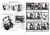
4. MECHANISM<br />
4.1 Mainboard Replacement<br />
1. Turn off the printer power.<br />
2. Remove the power cord and RS-232 and/or USB port cable.<br />
3. Open the top cover of the printer.<br />
4. Remove the four screws of the internal label roll mount.<br />
Remove screws of the label roll mount<br />
5. Move the mechanism about 5 mm in the label feed direction.<br />
6. Take out the internal label roll mount.<br />
Internal label<br />
roll mount<br />
15
<strong>TTP</strong>-<strong>244</strong> <strong>Plus</strong> <strong>Bar</strong> <strong>Code</strong><br />
<strong>Printer</strong> <strong>Service</strong> <strong>Manual</strong><br />
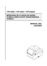
7. Remove all connectors on the main board.<br />
JP52<br />
JP42<br />
JP37<br />
Ground Wire<br />
JP14<br />
JP53<br />
JP46<br />
JP18<br />
Remark<br />
JP52<br />
JP37<br />
JP14<br />
JP53<br />
JP46<br />
JP18<br />
JP42<br />
Description<br />
Push button connector<br />
Ribbon encoder sensor & DC motor connector<br />
Stepping motor connector<br />
Gap sensor connector<br />
BLine sensor connector<br />
Ribbon sensor connector<br />
Print head connector<br />
8. Remove the screw of ground wire on the main board.<br />
9. Remove the rest three screws on the mainboard.<br />
10. Replace the mainboard.<br />
11. Reassemble the internal label roll mount in the reverse procedures of the removal.<br />
16
<strong>TTP</strong>-<strong>244</strong> <strong>Plus</strong> <strong>Bar</strong> <strong>Code</strong><br />
<strong>Printer</strong> <strong>Service</strong> <strong>Manual</strong><br />
4.2 DC Motor Replacement<br />
1. Turn off the printer power.<br />
2. Remove the power cord and RS-232 and/or USB port cable.<br />
3. Open the top cover of the printer.<br />
4. Remove the printer front panel.<br />
5. Remove the screws in the lower left, lower right corners of the main mechanism.<br />
Screws<br />
6. Remove all four screws of the internal label roll mount.<br />
17
<strong>TTP</strong>-<strong>244</strong> <strong>Plus</strong> <strong>Bar</strong> <strong>Code</strong><br />
<strong>Printer</strong> <strong>Service</strong> <strong>Manual</strong><br />
7. Move the mechanism in the label feed direction about 5 mm.<br />
8. Take out the internal label roll mount and remove connectors as below.<br />
9. Remove the screw of ground wire on the mainboard.<br />
JP42<br />
JP37<br />
Ground Wire<br />
JP14<br />
JP53<br />
JP46<br />
JP18<br />
10. Take out the mechanism.<br />
18
<strong>TTP</strong>-<strong>244</strong> <strong>Plus</strong> <strong>Bar</strong> <strong>Code</strong><br />
<strong>Printer</strong> <strong>Service</strong> <strong>Manual</strong><br />
11. Remove the one screw.<br />
Screw<br />
12. Remove the three screws on DC motor fixture.<br />
Screws<br />
DC Motor<br />
fixture<br />
13. Remove the three screws used to fix DC motor on the fixture and remove the cable tie.<br />
19
<strong>TTP</strong>-<strong>244</strong> <strong>Plus</strong> <strong>Bar</strong> <strong>Code</strong><br />
<strong>Printer</strong> <strong>Service</strong> <strong>Manual</strong><br />
Cable tie<br />
Screws<br />
14. Replace the DC motor and pull out the cables in connector JP 37.<br />
Note: The colors of DC motor wires in connector JP 37 are yellow (outside) and green<br />
(inside).<br />
15. Reassemble the removed parts in the reverse order of the removal.<br />
20
<strong>TTP</strong>-<strong>244</strong> <strong>Plus</strong> <strong>Bar</strong> <strong>Code</strong><br />
<strong>Printer</strong> <strong>Service</strong> <strong>Manual</strong><br />
4.3 Print Head Replacement<br />
1. Follow the instructions in Section 4.2 to take out the mechanism.<br />
2. Open the print carriage.<br />
3. Remove the screws, springs and spring bushing on both sides of the mechanism.<br />
Spring bushing<br />
Screws<br />
Spring<br />
Note: The left side spring and the right side spring are different in shape. The right<br />
side spring has a straight end, when the left side spring has an end that is<br />
curved 90 degrees.<br />
4. The main mechanism is divided into upper mechanism and lower mechanism.<br />
5. Disconnect the print head cables.<br />
6. Remove the e-ring at the mechanism, as shown.<br />
E-ring<br />
7. Remove the screws.<br />
21
<strong>TTP</strong>-<strong>244</strong> <strong>Plus</strong> <strong>Bar</strong> <strong>Code</strong><br />
<strong>Printer</strong> <strong>Service</strong> <strong>Manual</strong><br />
Screws<br />
8. Resplace the print head.<br />
9. Reassemble the removed parts in the reverse order of removal.<br />
Note:<br />
1. Tidy up the cable so that it does not protrude or interfere with the ribbon.<br />
2. Do not touch the elements of the print head.<br />
3. Do not disassemble the print head.<br />
22
<strong>TTP</strong>-<strong>244</strong> <strong>Plus</strong> <strong>Bar</strong> <strong>Code</strong><br />
<strong>Printer</strong> <strong>Service</strong> <strong>Manual</strong><br />
4.4 Ribbon Rewind Spindle Encoder Replacement<br />
The encoder is installed on the gear box of DC motor, and is used to detect if the ribbon<br />
is unerringly rewound by the spindle. The encoder is connected to JP6 on the<br />
mainboard. Please switch the printer to thermal transfer mode. The multi-meter is used<br />
to measure the voltage of Pin2 (+5V). If the voltage changes continuously from 0 to 5<br />
volts DC, the encoder is in condition. Otherwise, please follow the steps below to<br />
replace the encoder PCB.<br />
1. Follow directions in Section 4.2 to remove DC motor and DC motor fixture.<br />
DC Motor<br />
Encoder<br />
2. Remove the two flat tap screws and cable tie.<br />
3. Replace the Encoder PCB.<br />
4. Reassemble the removed parts in the reverse order of removal.<br />
23
<strong>TTP</strong>-<strong>244</strong> <strong>Plus</strong> <strong>Bar</strong> <strong>Code</strong><br />
<strong>Printer</strong> <strong>Service</strong> <strong>Manual</strong><br />
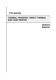
4.5 Felt Fabric Replacement<br />
Felt Fabric is located in the ribbon supply spindle. It is used to tighten the ribbon to<br />
prevent it from getting wrinkled during printing. If the ribbon can not be tightened when<br />
label back feeds during printing, please replace with a new felt to secure the best<br />
printing quality. Follow the steps below to replace the felt fabric.<br />
1. Follow the instructions in Section 4.2 to remove DC motor and DC motor fixture.<br />
2. Remove the E-ring and washer on ribbon supply spindle.<br />
E Ring<br />
Washer<br />
Spring Holder<br />
Spring<br />
Spring Cover<br />
Compression<br />
Spring<br />
Felt Clutch<br />
Felt Fabric<br />
Components of the<br />
Ribbon Supply Spindle<br />
3. Remove the spring cover, compression spring and spring holder.<br />
4. Remove the spring, felt clutch and felt fabric.<br />
5. Replace with a new felt.<br />
Side View of the<br />
Ribbon Supply Spindle Assembly<br />
24
<strong>TTP</strong>-<strong>244</strong> <strong>Plus</strong> <strong>Bar</strong> <strong>Code</strong><br />
<strong>Printer</strong> <strong>Service</strong> <strong>Manual</strong><br />
6. Reassemble the removed parts in the reverse order of removal.<br />
Front View of the<br />
Ribbon Supply Spindle<br />
25
<strong>TTP</strong>-<strong>244</strong> <strong>Plus</strong> <strong>Bar</strong> <strong>Code</strong><br />
<strong>Printer</strong> <strong>Service</strong> <strong>Manual</strong><br />
4.6 Stepping Motor Replacement<br />
1. Follow the instructions in Section 4.2 to take out the mechanism.<br />
2. Remove the two screws on stepping motor fixture.<br />
Screws<br />
3. Replace the stepping motor and reassemble the removed parts in the reverse order of removal.<br />
26
<strong>TTP</strong>-<strong>244</strong> <strong>Plus</strong> <strong>Bar</strong> <strong>Code</strong><br />
<strong>Printer</strong> <strong>Service</strong> <strong>Manual</strong><br />
4.7 Black Mark Sensor / Gap Sensor (Receiver) Replacement<br />
Black mark sensor is reflection type sensor. It is connected to JP4 (3 pin connector). A<br />
multi-meter is used to measure the signal of Pin2 to see if there is voltage variation<br />
when black mark is detected. Before conducting the test, please issue the BLINE<br />
command first. The printer will switch from gap sensor to black mark sensor. If there is<br />
no voltage variation, please follow steps below to replace the black mark sensor / gap<br />
sensor (receiver) PCB.<br />
1. Follow the instructions in Section 4.2 to take out the mechanism.<br />
Black mark<br />
sensor PCB<br />
2. Remove two flat tap screws and black mark sensor PCB.<br />
Screws<br />
3. Reassemble the removed parts in the reverse order of removal.<br />
27
<strong>TTP</strong>-<strong>244</strong> <strong>Plus</strong> <strong>Bar</strong> <strong>Code</strong><br />
<strong>Printer</strong> <strong>Service</strong> <strong>Manual</strong><br />
4.8 Ribbon Sensor (Receiver) Replacement<br />
1. Follow the instructions in Section 4.2 to take out the mechanism.<br />
2. Open the print carriage.<br />
3. Remove the screws, springs and spring bushing on both sides of the mechanism.<br />
Spring bushing<br />
Screws<br />
Spring<br />
Note: The left side spring and the right side spring are different in shape. The right<br />
side spring has a straight end, when the left side spring has an end that is<br />
curved 90 degrees.<br />
4. The main mechanism is divided into upper mechanism and lower mechanism.<br />
5. And ribbon sensor (receiver) is located in the upper mechanism. Remove the screws on the<br />
ribbon sensor cover.<br />
28
<strong>TTP</strong>-<strong>244</strong> <strong>Plus</strong> <strong>Bar</strong> <strong>Code</strong><br />
<strong>Printer</strong> <strong>Service</strong> <strong>Manual</strong><br />
Sensor Cover<br />
Flat Tap Screw<br />
6. Replace with a new ribbon sensor PCB.<br />
Ribbon sensor PCB<br />
7. Reassemble the removed parts in the reverse order of removal.<br />
29
<strong>TTP</strong>-<strong>244</strong> <strong>Plus</strong> <strong>Bar</strong> <strong>Code</strong><br />
<strong>Printer</strong> <strong>Service</strong> <strong>Manual</strong><br />
4.9 Ribbon Sensor (Transmitter) / Gap Sensor (Transmitter) Replacement<br />
1. Please follow the steps in Section 4.8 to separate the upper mechanism from the lower<br />
mechanism.<br />
2. The ribbon sensor (transmitter) is located in the center of the lower mechanism.<br />
Ribbon sensor<br />
(transmitter) PCB<br />
3. Remove the two flat tap screws<br />
Screws<br />
4. Remove the cable tie and sensor PCB.<br />
5. Replace with a new PCB. Reassemble the removed parts in the reverse order of removal.<br />
30
<strong>TTP</strong>-<strong>244</strong> <strong>Plus</strong> <strong>Bar</strong> <strong>Code</strong><br />
<strong>Printer</strong> <strong>Service</strong> <strong>Manual</strong><br />
4.10 Platen Replacement<br />
1. Follow the instructions in Section 4.6 to remove the stepping motor fixture and stepping motor.<br />
2. Remove the E-ring and two gears.<br />
3. Remove the E ring and the printer carriage release lever arm.<br />
Thermal Head<br />
<strong>Printer</strong> Carriage<br />
Release lever arm<br />
Gear #1<br />
E-ring<br />
Gear #2<br />
4. Remove the E-ring and the printer carriage release lever on the left side of the mechanism.<br />
<strong>Printer</strong> Carriage<br />
Release Lever<br />
E-ring<br />
31
<strong>TTP</strong>-<strong>244</strong> <strong>Plus</strong> <strong>Bar</strong> <strong>Code</strong><br />
<strong>Printer</strong> <strong>Service</strong> <strong>Manual</strong><br />
5. Remove the teflon tube and stripper rod.<br />
Teflon Tube<br />
6. Remove the E ring, the right side and left side platen bushes.<br />
Platen<br />
E-ring<br />
Platen bush (Left side)<br />
7. Move the platen to the right of the mechanism.<br />
8. Replace the platen and reassemble the removed parts in the reverse order of removal.<br />
32
<strong>TTP</strong>-<strong>244</strong> <strong>Plus</strong> <strong>Bar</strong> <strong>Code</strong><br />
<strong>Printer</strong> <strong>Service</strong> <strong>Manual</strong><br />
5. TROUBLE SHOOTING<br />
5.1 Trouble Shooting<br />
Problems<br />
Solutions<br />
1. Ribbon does not advance. Check the printing mode setting and reset the<br />
printer.<br />
2. Poor print quality. Clean the print head.<br />
Adjust the print density setting.<br />
3. Only prints diagonal pattern in the self-test. Ribbon and paper are incompatible. Use a<br />
different type of ribbon.<br />
4. Power indicator light does not illuminate. Check the connection of serial port cable.<br />
5. On-line indicator light does not to illuminate. Check the DIP switch setting and reset the<br />
printer.<br />
Check that power cord is properly connected.<br />
6. Error indicator remains illuminated. Out of paper or out of ribbon.<br />
Check the DIP switch setting<br />
Check the paper core, make sure it is installed<br />
on the ribbon rewind spindle.<br />
Press the FEED key. The error message will<br />
be printed out on the print media or sent out<br />
through RS-232 port.<br />
If there is no problem with direct thermal<br />
printing, but error occurs in thermal transfer<br />
printing. Please check the encoder of the DC<br />
motor.<br />
33
<strong>TTP</strong>-<strong>244</strong> <strong>Plus</strong> <strong>Bar</strong> <strong>Code</strong><br />
<strong>Printer</strong> <strong>Service</strong> <strong>Manual</strong><br />
5.2 Calibrate the Gap Register<br />
Install the label.<br />
Turn on the printer power while pressing the PAUSE button. The printer will calibrate the<br />
transparency of the backing paper and adjust the gap register.<br />
5.3 Self-test<br />
Install the label.<br />
Turn on the printer power while pressing the FEED button, the printer will:<br />
Print head checking pattern.<br />
Calibrate the label length.<br />
Print internal settings.<br />
Initiate self-test.<br />
Enter dump mode.<br />
5.4 Ram Clear<br />
Press the PAUSE and FEED button simultaneously for more than 3 seconds. The printer will<br />
clear the memory and reset the printer.<br />
Be sure to calibrate the gap register with blank label before printing.<br />
5.5 Diagnosis Operation Procedure<br />
When the power is turned on without any button pressed, self diagnosis is performed<br />
automatically to test the available memory. If any error occurs during this period, the ERR<br />
light will flash.<br />
Do the self test and inspect the test pattern to check if the thermal head is available.<br />
34
<strong>TTP</strong>-<strong>244</strong> <strong>Plus</strong> <strong>Bar</strong> <strong>Code</strong><br />
<strong>Printer</strong> <strong>Service</strong> <strong>Manual</strong><br />
5.6 Testing Sensors<br />
A. Checking Ribbon Sensor<br />
Switch the multimeter to the DC gear. Connect the black wire to DC GND, and the red<br />
wire to PIN2 of JP18.<br />
1. When ribbon is detected between TX and RX of the ribbon sensor, the measured<br />
voltage should be 5 Vdc.<br />
2. When ribbon is not detected between TX and RX of the ribbon sensor, the measured<br />
voltage should be 0 Vdc.<br />
The ribbon sensor is normal if the checking complies with the two cases above. Or else,<br />
the ribbon sensor is out of order.<br />
B. Checking DC Motor Encoder Sensor<br />
Switch the multimeter to the DC gear. Connect the black wire to DC GND, and the red<br />
wire to PIN4 of U35.<br />
1. When gap of the gear box is detected by the DC motor encoder sensor, the<br />
measured voltage should be 5 Vdc.<br />
2. When gap of the gear box is not detected by the DC motor encoder sensor, the<br />
measured voltage should be 0 Vdc.<br />
The DC motor encoder sensor is normal if the checking complies with the two cases<br />
above. Or else, the DC motor encoder sensor is out of order.<br />
C. Checking Black Line Sensor<br />
Switch the multimeter to the DC gear. Connect the black wire to DC GND, and the red<br />
wire to PIN2 of U2. Load black line label on the printer.<br />
1. When black line is detected by the black line sensor, the measured voltage should<br />
be 3 Vdc.<br />
2. When black line is not detected by the black line sensor, the measured voltage<br />
should be 0 Vdc.<br />
The black line sensor is normal if the checking complies with the two cases above. Or<br />
else, the black line sensor is out of order.<br />
35
<strong>TTP</strong>-<strong>244</strong> <strong>Plus</strong> <strong>Bar</strong> <strong>Code</strong><br />
<strong>Printer</strong> <strong>Service</strong> <strong>Manual</strong><br />
UPDATE HISTORY<br />
Date Content Editor<br />
2009/10/6 Modify section 3.1 Camille<br />
2011/1/25 Modify <strong>TSC</strong> address Camille<br />
2011/4/7 Modify section 3.2 Camille<br />
36
<strong>TSC</strong> Auto ID Technology Co., Ltd.<br />
Corporate Headquarters<br />
Li Ze Plant<br />
9F., No.95, Minquan Rd., Xindian Dist., No.35, Sec. 2, Ligong 1st Rd., Wujie Township,<br />
New Taipei City 23141, Taiwan (R.O.C.) Yilan County 26841, Taiwan (R.O.C.)<br />
TEL: +886-2-2218-6789 TEL: +886-3-990-6677<br />
FAX: +886-2-2218-5678 FAX: +886-3-990-5577<br />
Web site: www.tscprinters.com<br />
E-mail: printer_sales@tscprinters.com<br />
tech_support@tscprinters.com