TTP-246M/344M Bar Code Printer Service Manual - TSC
TTP-246M/344M Bar Code Printer Service Manual - TSC
TTP-246M/344M Bar Code Printer Service Manual - TSC

Create successful ePaper yourself
Turn your PDF publications into a flip-book with our unique Google optimized e-Paper software.
<strong>TTP</strong> <strong>246M</strong>/<strong>344M</strong><br />
THERMAL TRANSFER / DIRECT THERMAL<br />
BAR CODE PRINTER<br />
SERVICE<br />
MANUAL
<strong>TTP</strong>-<strong>246M</strong>/<strong>344M</strong> <strong>Bar</strong> <strong>Code</strong> <strong>Printer</strong><br />
<strong>Service</strong> <strong>Manual</strong><br />
TABLE OF CONTENT<br />
1. Foundamentals About the System .............................................................................. 1<br />
1.1<strong>Printer</strong> Overview ........................................................................................................ 1<br />
1.1.1 Front View ........................................................................................................ 1<br />
1.1.2 Rear View ........................................................................................................ 1<br />
1.2 Pinter Specification ................................................................................................... 2<br />
1.3 Available <strong>Bar</strong> <strong>Code</strong>s ................................................................................................. 4<br />
2. Supply Specifications ................................................................................................. 5<br />
2.1 Label Specification ................................................................................................... 5<br />
2.2 Ribbon Specification ................................................................................................. 5<br />
3. Circuit Description ....................................................................................................... 7<br />
3.1 PCB Function ........................................................................................................... 7<br />
3.2 MCU PIN Description ............................................................................................... 9<br />
3.3 Reset Circuit ........................................................................................................... 11<br />
3.4 Memory Circuit ....................................................................................................... 11<br />
3.5 Decoder Circuit and Memory Map .......................................................................... 12<br />
3.6 Print Head Circuit ................................................................................................... 15<br />
3.7 Motor Circuit ........................................................................................................... 16<br />
3.8 Cutter Circuit .......................................................................................................... 16<br />
3.9 Parallel Port Circuit................................................................................................. 17<br />
3.10 Serial Port Circuit ................................................................................................. 17<br />
3.11 USB Circuit ........................................................................................................... 18<br />
3.11.1 Gap/Black Mark sensor ..................................................................................... 18<br />
3.11.2 Case Open Sensor ............................................................................................ 19<br />
3.11.3 Ribbon End Sensor ........................................................................................... 19<br />
3.11.4 Head Open Sensor ............................................................................................ 20<br />
3.11.5 Peel-off Sensor .................................................................................................. 20<br />
3.12 Summary of PCB connectors ......................................................................... 21<br />
3.12.1 <strong>TTP</strong>-<strong>246M</strong> & <strong>344M</strong> PCB Top Side ..................................................................... 22<br />
3.12.2 <strong>TTP</strong>-<strong>246M</strong> & <strong>344M</strong> PCB Bottom Side ............................................................... 23<br />
4. Mechanism ............................................................................................................... 24<br />
4.1 Remove Covers, LCD Panel and Lower Front Panel ............................................. 24<br />
4.2 Replacing the All Harness on Main PCB ................................................................ 28<br />
4.3 Replacing Power Supply Unit ................................................................................. 29<br />
4.4 Replacing Belt and Gears ...................................................................................... 30<br />
4.5 Replacing Ribbon Rewind Spindle ......................................................................... 33<br />
i
<strong>TTP</strong>-<strong>246M</strong>/<strong>344M</strong> <strong>Bar</strong> <strong>Code</strong> <strong>Printer</strong><br />
<strong>Service</strong> <strong>Manual</strong><br />
4.6 Replacing Ribbon Supply Spindle .......................................................................... 35<br />
4.7 Replacing Label Supply Spindle ............................................................................. 37<br />
4.8 Replacing Platen .................................................................................................... 39<br />
4.9 Replacing Stepping Motor ...................................................................................... 41<br />
4.10 Replacing Print Head ........................................................................................... 42<br />
4.11 Replacing Print Head Adjustment Knob ................................................................ 43<br />
4.12 Replacing Gap / Black Mark Sensor ..................................................................... 45<br />
4.13 Replacing Ribbon Sensor ..................................................................................... 48<br />
4.14 Replacing Print Head Lift Sensor ......................................................................... 50<br />
4.15 Replacing Internal Print Server Module ................................................................ 51<br />
4.16 Peeler Kit Installation (Option).............................................................................. 54<br />
4.17 Loading Label For Peel-off Mode ......................................................................... 60<br />
4.18 Cutter Module Installation (Option)....................................................................... 63<br />
5. POWER ON UTILITIES ............................................................................................ 64<br />
5.1 Calibrate Gap/Black Mark Sensor .......................................................................... 64<br />
5.2 Self-test .................................................................................................................. 64<br />
5.3 <strong>Printer</strong> Initialization ................................................................................................. 65<br />
6. Troubleshooting ........................................................................................................ 67<br />
7. MAINTENANCE ....................................................................................................... 69<br />
Update History.............................................................................................................. 70<br />
ii
<strong>TTP</strong>-<strong>246M</strong>/<strong>344M</strong> <strong>Bar</strong> <strong>Code</strong> <strong>Printer</strong><br />
<strong>Service</strong> <strong>Manual</strong><br />
1. FOUNDAMENTALS ABOUT THE SYSTEM<br />
1.1<strong>Printer</strong> Overview<br />
1.1.1 Front View<br />
Aux. LED<br />
LCD Display<br />
<strong>Printer</strong> Right<br />
Side Cover<br />
Keys<br />
Fig. 1.1 <strong>Printer</strong> Front View<br />
1.1.2 Rear View<br />
External Label<br />
Feed Opening<br />
Centronics Port<br />
RS-232C Port<br />
Power Switch<br />
Power Supply<br />
Connector<br />
Fig. 1.2 <strong>Printer</strong> Rear View<br />
1
<strong>TTP</strong>-<strong>246M</strong>/<strong>344M</strong> <strong>Bar</strong> <strong>Code</strong> <strong>Printer</strong><br />
<strong>Service</strong> <strong>Manual</strong><br />
1.2 Pinter Specification<br />
Item<br />
Printing Mode<br />
Resolution<br />
Max. Print Length<br />
Max. Print Width<br />
Print Speed<br />
Specification<br />
Thermal transfer and direct thermal<br />
203DPI(<strong>TTP</strong><strong>246M</strong>), 300 DPI (<strong>TTP</strong><strong>344M</strong>)<br />
1000 mm (<strong>TTP</strong><strong>246M</strong>), 460 mm (<strong>TTP</strong><strong>344M</strong>)<br />
108 mm (<strong>TTP</strong><strong>246M</strong>), 104 mm (<strong>TTP</strong><strong>344M</strong>)<br />
3,4,5,6 ips (<strong>TTP</strong><strong>246M</strong>); 2,3,4 ips (<strong>TTP</strong><strong>344M</strong>)<br />
Environment<br />
Temperature<br />
5 ~40 O C<br />
Humidity 30 ~ 85 %<br />
Temperature<br />
-10 ~ 60 O C<br />
Humidity 20 ~ 95 %<br />
Ventilation<br />
Free air environment<br />
Electrical<br />
Sensors<br />
Interface<br />
Cutter<br />
Power<br />
Other<br />
CPU<br />
TPH<br />
Stepping Motor<br />
Compliance<br />
Memory<br />
Label gap sensor, ribbon end sensor, black mark<br />
sensor, head open sensor, label taken sensor<br />
RS-232C (RS422/485 option), Centronics (SPP),<br />
USBV1.1 and internal LAN adapter (option).<br />
4 inch width (Paper thickness up to 0.25 mm)<br />
100-240 V universal switching power supply.<br />
Real Time Clock<br />
HITACH SH2 7040A<br />
<strong>246M</strong> KPC-108-8TA01<br />
<strong>344M</strong> KPC-106-12TA01<br />
KH42JM2B165<br />
CE, UL/CUL, BSMI, FCC Class A, TÜ V-GS<br />
Flash ROM (2MB), DRAM (2MB) and 8M optional flash<br />
ROM (memory module)<br />
2
<strong>TTP</strong>-<strong>246M</strong>/<strong>344M</strong> <strong>Bar</strong> <strong>Code</strong> <strong>Printer</strong><br />
<strong>Service</strong> <strong>Manual</strong><br />
Communication Interface<br />
Communication<br />
Word Length<br />
RS-232C (DB-9) at 2400, 4800, 9600 or 19200 baud<br />
rate<br />
7 or 8 data bits, 1 or 2 stop bits, selectable parity<br />
Communication Protocol XON/XOFF and DSR/DTR<br />
Parallel Port<br />
Input Buffer<br />
Standard parallel interface<br />
10KB<br />
• RS-232 Interface Pin Configuration<br />
Host<br />
Function<br />
9 Pin 25 Pin 9 Pin <strong>Printer</strong> Function<br />
1 +5V<br />
RxD 2 3 2 TxD<br />
TxD 3 2 3 RxD<br />
DTR 4 20 4 DSR<br />
GND 5 7 5 GND<br />
DSR 6 6 6 RDY<br />
RTS 7 4 7 N/C<br />
CTS 8 5 8 RDY<br />
9 +5V<br />
• Cutter off Mini-DIN Connector Pin Assignment<br />
Mini-DIN<br />
Pin 1<br />
Pin2<br />
Pin 3<br />
Pin 4<br />
PCB JP10 connector<br />
Pin 1, brown<br />
Pin 3, red<br />
Pin 2, orange<br />
Pin 4, yellow<br />
• Peeler Mini-DIN Connector Pin Assignment<br />
3
<strong>TTP</strong>-<strong>246M</strong>/<strong>344M</strong> <strong>Bar</strong> <strong>Code</strong> <strong>Printer</strong><br />
<strong>Service</strong> <strong>Manual</strong><br />
Mini-DIN<br />
Pin 5<br />
Pin 6<br />
Pin 7<br />
Pin 8<br />
PCB JP20 connector<br />
Pin 1, brown<br />
Pin 2, red<br />
Pin 3, orange<br />
Pin 4, yellow<br />
1.3 Available <strong>Bar</strong> <strong>Code</strong>s<br />
• <strong>Code</strong> 39<br />
• <strong>Code</strong> 39C<br />
• <strong>Code</strong> 93<br />
• <strong>Code</strong>128 subsets A.B.C<br />
• Codabar<br />
• Interleave 2 of 5<br />
• EAN-8<br />
• EAN-13<br />
• EAN-128<br />
• UPC-A<br />
• UPC-E<br />
• EAN and UPC 2(5) digits add-on<br />
• CPOST<br />
• MSI<br />
• PLESSEY<br />
• POSTNET<br />
• EAN-14<br />
• ITF-14<br />
• PDF-417<br />
• Maxicode<br />
• DataMatrix<br />
• QR code<br />
4
<strong>TTP</strong>-<strong>246M</strong>/<strong>344M</strong> <strong>Bar</strong> <strong>Code</strong> <strong>Printer</strong><br />
<strong>Service</strong> <strong>Manual</strong><br />
2. SUPPLY SPECIFICATIONS<br />
2.1 Label Specification<br />
Item<br />
Specification<br />
Type<br />
Roll and label (Continuous, die-cut, fan-fold, ticket and<br />
tag is option)<br />
Label Width 25.4~116 mm ( 1”~4.4” )<br />
<strong>TTP</strong>-<strong>246M</strong> 10~1000 mm ( 0.4”~39.33” )<br />
Label Length<br />
<strong>TTP</strong>-<strong>344M</strong> 10~460 mm (0.4”~18”)<br />
Label Thickness<br />
Label Roll Diameter<br />
Roll Up Method<br />
Roll Core Diameter<br />
Black Mark Width<br />
0.06~0.25 mm<br />
203 mm (Max.)<br />
Print surface wound outside as standard.<br />
25 or 77 mm<br />
3 mm ( Min.)<br />
2.2 Ribbon Specification<br />
Item<br />
Ribbon Width<br />
Ribbon Length<br />
25.4~114.3 mm<br />
300 m (Max.)<br />
Specification<br />
Note: The maximum length of ribbon depends on its thickness and core outside<br />
diameter.<br />
The formula below defines the correlation between ribbon roll length and ribbon core<br />
diameter.<br />
2 2<br />
(D d ) <br />
L =<br />
where<br />
4t ,<br />
5
<strong>TTP</strong>-<strong>246M</strong>/<strong>344M</strong> <strong>Bar</strong> <strong>Code</strong> <strong>Printer</strong><br />
<strong>Service</strong> <strong>Manual</strong><br />
L = Ribbon length<br />
D = Max. roll diameter<br />
d = Ribbon core outside diameter<br />
t = Ribbon thickness<br />
6
<strong>TTP</strong>-<strong>246M</strong>/<strong>344M</strong> <strong>Bar</strong> <strong>Code</strong> <strong>Printer</strong><br />
<strong>Service</strong> <strong>Manual</strong><br />
3. CIRCUIT DESCRIPTION<br />
3.1 PCB Function<br />
The mainboard of <strong>TTP</strong>-<strong>344M</strong>/<strong>246M</strong> includes nine system blocks.<br />
1. Memory System<br />
2. Sensor System<br />
3. Decoder System<br />
4. RTC, EEPROM, LCD System<br />
5. Print Head Connector System<br />
6. Motor System<br />
7. Power System<br />
8. USB System<br />
9. Communication Port<br />
7
<strong>TTP</strong>-<strong>246M</strong>/<strong>344M</strong> <strong>Bar</strong> <strong>Code</strong> <strong>Printer</strong><br />
<strong>Service</strong> <strong>Manual</strong><br />
The figure below shows the PCB system areas:<br />
Communication<br />
Port<br />
Memory<br />
System<br />
MCU<br />
Sensor<br />
System<br />
RTC,<br />
EPROM<br />
, LCD<br />
Decoder<br />
Print<br />
Head<br />
Connector<br />
USB<br />
System<br />
Power<br />
System<br />
Motor<br />
System<br />
Fig.3.1 System Block of PCB<br />
8
<strong>TTP</strong>-<strong>246M</strong>/<strong>344M</strong> <strong>Bar</strong> <strong>Code</strong> <strong>Printer</strong><br />
<strong>Service</strong> <strong>Manual</strong><br />
3.2 MCU PIN Description<br />
A. The Function is follow 40-0220001-02 PCB version.<br />
Port I/O High Low Function Instruction<br />
PD0~PD15 I/O Data D0~D15 Data bus<br />
PC0~PC15 O Address A0~A15 Address bus<br />
PB0~PB1 O Address A16~A17 Address bus<br />
PB6~PB9 O Address A18~A21 Address bus<br />
PB2 O Active /RAS DRAM control signal<br />
PB.3 O Active /CASL DRAM control signal<br />
PB.4 O Active /CASH DRAM control signal<br />
PB5 O Read Write RDWR DRAM control signal<br />
PA0 I RXD0 RS232 RX<br />
PA1 O TXD0 RS232 DX<br />
PA2 I Active IRQ0 /Select In<br />
PA3 O PA3 RS232 CTS<br />
PA4 O TXD1 TPH Data In<br />
PA5 O SCK1 TPH Clock<br />
PA6 O Active /CS2 CS2<br />
PA7 O Active /CS3 CS3<br />
PA8 I Active IRQ2 Centronic port /AF<br />
PA9 I Active IRQ3 USB interrupt<br />
PA10 O Active /CS0 CS0<br />
PA11 O Active /CS1 CS1<br />
PA12 O Active /WRL Write Low Byte<br />
PA13 O Active /WRH Write High Byte<br />
PA14 O Active /RD Read<br />
PA15 O Active PA15 TPH Latch<br />
PE0 O Active PE0 TPH Strobe 1<br />
PE1 O Active PE1 TPH Strobe 2<br />
PE2 O Enable PE2 LED 1 (L1)<br />
PE3 O Active PE3 TPH Power Enable<br />
PE4 I Enable PE4 Menu Key<br />
PE5 O Enable PE5 LED 2 (L2)<br />
9
<strong>TTP</strong>-<strong>246M</strong>/<strong>344M</strong> <strong>Bar</strong> <strong>Code</strong> <strong>Printer</strong><br />
<strong>Service</strong> <strong>Manual</strong><br />
PE6 I TIOC2A Ribbon Near End Sensor<br />
PE7 O Enable PE7 LED 3 (L3)<br />
PE8 I TIOC3A Paper Near End Sensor<br />
PE9 I/O PE9 EEPROM SDO&SDI<br />
PE10 O Enable PE10 EEPROM Chip Select<br />
PE11 O PE11 EEPROM Clock<br />
PE12 I/O PE12 USB Suspend<br />
PE13 I Enable PE13 Pause Key<br />
PE14 I Enable PE14 Feed Key<br />
PE15 I Enable PE15 Head Sensor<br />
PF0 I AN0 TPH Voltage<br />
PF1 I AN1 TPH Temperature<br />
PF2 I Enable PF2 Cutter Sensor<br />
PF3 I PF3 RS232 RTS<br />
PF4 I Enable PF4 Peel Sensor<br />
PF5 I Enable PF5 Ribbon End Sensor<br />
PF6 I Enable PF6 Black Mark Sensor<br />
PF7 I Enable PF7 Gap Sensor<br />
NMI I Active NMI Power Down<br />
/WDTOVF O Active (Reserve)<br />
B. Other define<br />
1. Crystal is 7.15909 MHz.<br />
2. Option mode is mode 1. ( MD0 is high, MD1 is low. )<br />
3. Clock mode is PLL ON x 4. ( MD2 is low, MD3 is high. )<br />
4. Vcc is 5V, AVcc is 5V.<br />
10
<strong>TTP</strong>-<strong>246M</strong>/<strong>344M</strong> <strong>Bar</strong> <strong>Code</strong> <strong>Printer</strong><br />
<strong>Service</strong> <strong>Manual</strong><br />
3.3 Reset Circuit<br />
This is reset circuit. The 80846 is voltage detecting IC. It can detect the voltage while the<br />
voltage is up to 4.6V;its output signal is high.<br />
3.4 Memory Circuit<br />
There are 2MB DRAM and 2MB flash ROM on board.<br />
JP7 is memory card connector. The memory card can be expanded to 8MB.<br />
11
<strong>TTP</strong>-<strong>246M</strong>/<strong>344M</strong> <strong>Bar</strong> <strong>Code</strong> <strong>Printer</strong><br />
<strong>Service</strong> <strong>Manual</strong><br />
3.5 Decoder Circuit and Memory Map<br />
The CPLD is used to decode the memory and other function.<br />
Please refer to the memory map below.<br />
12
<strong>TTP</strong>-<strong>246M</strong>/<strong>344M</strong> <strong>Bar</strong> <strong>Code</strong> <strong>Printer</strong><br />
<strong>Service</strong> <strong>Manual</strong><br />
Memory Map<br />
13
<strong>TTP</strong>-<strong>246M</strong>/<strong>344M</strong> <strong>Bar</strong> <strong>Code</strong> <strong>Printer</strong><br />
<strong>Service</strong> <strong>Manual</strong><br />
Definition of other decode function<br />
14
<strong>TTP</strong>-<strong>246M</strong>/<strong>344M</strong> <strong>Bar</strong> <strong>Code</strong> <strong>Printer</strong><br />
<strong>Service</strong> <strong>Manual</strong><br />
3.6 Print Head Circuit<br />
STB1, and STB2 are the print head heating signal. There is a limit for RC heating time of<br />
U15 (74HC123), it can avoid the print head over-heating.<br />
U26 is used to protect print head and avoid the current appears in the improper time.<br />
15
<strong>TTP</strong>-<strong>246M</strong>/<strong>344M</strong> <strong>Bar</strong> <strong>Code</strong> <strong>Printer</strong><br />
<strong>Service</strong> <strong>Manual</strong><br />
3.7 Motor Circuit<br />
This is motor circuit. U12 and U13 are drivers to control the bipolar stepping motor by using<br />
full step control method<br />
3.8 Cutter Circuit<br />
16
<strong>TTP</strong>-<strong>246M</strong>/<strong>344M</strong> <strong>Bar</strong> <strong>Code</strong> <strong>Printer</strong><br />
<strong>Service</strong> <strong>Manual</strong><br />
U15B (74HC123) controls the breaking of U14. U14 is the driver of cutter’s DC motor.<br />
3.9 Parallel Port Circuit<br />
Centronics port is SPP mode and one-way communication.<br />
3.10 Serial Port Circuit<br />
U18 (SP232A) is RS232 asynchronous communication driver IC.<br />
U19 is used for industrial long-distance asynchronous communication;U19 is optional for<br />
RS-422/485.<br />
17
<strong>TTP</strong>-<strong>246M</strong>/<strong>344M</strong> <strong>Bar</strong> <strong>Code</strong> <strong>Printer</strong><br />
<strong>Service</strong> <strong>Manual</strong><br />
3.11 USB Circuit<br />
This is USB circuit. This is standard USB1.1.<br />
3.11.1 Gap/Black Mark sensor<br />
1. The gap sensor is see-through sensor with 32 levels.<br />
2. Black mark sensor is reflective sensor with 32 levels.<br />
3. The GAP_ SENS signal is” HIGH“ when the gap sens detected gap; the BM_SENS<br />
signal is “HIGH“ when the block mark sens detected block mark.<br />
4. The gap sensor activates when GAP& Black mark SW signal is high; the black mark<br />
sensor activates when GAP& BM_SW signal is low.<br />
18
<strong>TTP</strong>-<strong>246M</strong>/<strong>344M</strong> <strong>Bar</strong> <strong>Code</strong> <strong>Printer</strong><br />
<strong>Service</strong> <strong>Manual</strong><br />
3.11.2 Case Open Sensor<br />
This is case open sensor circuit. Case open sensor is a see-through sensor. The case opens<br />
when the CASE SENS signal is low; the case closes when the CASE SENS signal is high.<br />
3.11.3 Ribbon End Sensor<br />
Ribbon end sensor is a see-through sensor.<br />
1. There are 8 levels of adjustment tension to adapt different ribbons.<br />
2. The REND SENS signal is high when there is ribbon inside; the REND SENS signal is<br />
low when there is no ribbon.<br />
3. The ribbon end tape should be transparent.<br />
19
<strong>TTP</strong>-<strong>246M</strong>/<strong>344M</strong> <strong>Bar</strong> <strong>Code</strong> <strong>Printer</strong><br />
<strong>Service</strong> <strong>Manual</strong><br />
3.11.4 Head Open Sensor<br />
This is the see-through sensor. The HEAD SENS signal is "High" when print head opens;<br />
The HEAD SENS signal is "Low" when the print head closes.<br />
3.11.5 Peel-off Sensor<br />
This is a reflective sensor. The PEEL SENS signal is high when there is label below the<br />
sensor; the PEEL SENS signal is low when the label is taken away.<br />
20
<strong>TTP</strong>-<strong>246M</strong>/<strong>344M</strong> <strong>Bar</strong> <strong>Code</strong> <strong>Printer</strong><br />
<strong>Service</strong> <strong>Manual</strong><br />
3.12 Summary of PCB connectors<br />
Connector Description Remark<br />
JP1 CPLD JTAG connector For CPLD program update<br />
JP2 Boot memory load jumper<br />
JP3 Reserved<br />
JP4 Reserved<br />
JP5 Power connector<br />
JP7 Memory card connector<br />
JP8 LCD module connector<br />
JP9 Stepping motor connector<br />
JP10 Cutter module connector<br />
JP11 TPH connector<br />
JP12 Centronics port connector<br />
JP13 USB connector<br />
JP15 RS-232 connector<br />
JP16 Gap/black sensor connector<br />
JP17 Ribbon end sensor<br />
JP18 Case open sensor<br />
JP19 Ribbon near end sensor<br />
JP20 Peel connector For direct Thermal printer<br />
only<br />
JP21 Head open sensor<br />
JP22 Paper near end sensor<br />
JP33 300 dpi TPH protect jumper<br />
JP34 300 dpi TPH protect jumper<br />
JP35 Reserved<br />
JP37 5V DC connector Provide 5V DC, 0.3A<br />
JP38 Reserved<br />
21
<strong>TTP</strong>-<strong>246M</strong>/<strong>344M</strong> <strong>Bar</strong> <strong>Code</strong> <strong>Printer</strong><br />
<strong>Service</strong> <strong>Manual</strong><br />
3.12.1 <strong>TTP</strong>-<strong>246M</strong> & <strong>344M</strong> PCB Top Side<br />
JP23 JP37 JP18 JP22 JP17 JP19 JP20 JP21<br />
JP8<br />
JP12<br />
JP33<br />
JP34<br />
JP11<br />
JP15<br />
JP2<br />
JP36<br />
JP13<br />
JP16<br />
JP10<br />
JP9<br />
JP1<br />
JP36<br />
JP5<br />
Cutter Driver IC 3953<br />
22
<strong>TTP</strong>-<strong>246M</strong>/<strong>344M</strong> <strong>Bar</strong> <strong>Code</strong> <strong>Printer</strong><br />
<strong>Service</strong> <strong>Manual</strong><br />
3.12.2 <strong>TTP</strong>-<strong>246M</strong> & <strong>344M</strong> PCB Bottom Side<br />
Stepping Motor Driver IC<br />
23
<strong>TTP</strong>-<strong>246M</strong>/<strong>344M</strong> <strong>Bar</strong> <strong>Code</strong> <strong>Printer</strong><br />
<strong>Service</strong> <strong>Manual</strong><br />
4. Mechanism<br />
4.1 Remove Covers, LCD Panel and Lower Front Panel<br />
1. Open Top Right Side Cover.<br />
Top Right Side Cover<br />
2. Loosen four screws to separate the Top Right Side Cover and Main Frame.<br />
Screws<br />
Screws<br />
24
<strong>TTP</strong>-<strong>246M</strong>/<strong>344M</strong> <strong>Bar</strong> <strong>Code</strong> <strong>Printer</strong><br />
<strong>Service</strong> <strong>Manual</strong><br />
3. Remove Top Right Side Cover.<br />
4. Loosen three screws to separate Main Frame and Left Side Cover.<br />
Screws<br />
25
<strong>TTP</strong>-<strong>246M</strong>/<strong>344M</strong> <strong>Bar</strong> <strong>Code</strong> <strong>Printer</strong><br />
<strong>Service</strong> <strong>Manual</strong><br />
5. Loosen screws on Top Left Side Cover.<br />
Top Left Side Cover<br />
6. Remove Left Side Cover.<br />
7. Loosen two screws to separate the LCD panel and Main Frame, remove the<br />
connector from LCD panel, and then remove LCD panel.<br />
Screws<br />
26
<strong>TTP</strong>-<strong>246M</strong>/<strong>344M</strong> <strong>Bar</strong> <strong>Code</strong> <strong>Printer</strong><br />
<strong>Service</strong> <strong>Manual</strong><br />
8. Loosen four screws and then remove Lower Front Cover.<br />
Screws<br />
Screws<br />
Lower front cover<br />
9. Reassemble in the reverse procedures.<br />
27
<strong>TTP</strong>-<strong>246M</strong>/<strong>344M</strong> <strong>Bar</strong> <strong>Code</strong> <strong>Printer</strong><br />
<strong>Service</strong> <strong>Manual</strong><br />
4.2 Replacing the All Harness on Main PCB<br />
1. Disconnect the printer power cord.<br />
2. Refer to section 4.1 to remove the left side cover.<br />
3. Disconnect all harness.<br />
4. Remove screws on Mainboard and replace the Main PCB.<br />
Main PCB<br />
5. Reassemble in the reverse procedures.<br />
28
<strong>TTP</strong>-<strong>246M</strong>/<strong>344M</strong> <strong>Bar</strong> <strong>Code</strong> <strong>Printer</strong><br />
<strong>Service</strong> <strong>Manual</strong><br />
4.3 Replacing Power Supply Unit<br />
1. Disconnect the printer power cord.<br />
2. Refer to section 4.1 to remove the left side cover.<br />
3. The left side (face to power switch) harness of power switch is red, and the right side<br />
harness is black.<br />
4. Disconnect JP5 harness from the main PCB.<br />
5. Disconnect the harness that is connected between power switch and power supply<br />
unit.<br />
6. Loosen four screws on power supply unit, which is fixed onto the printer.<br />
Power Supply Unit<br />
7. Replace Power Supply Unit.<br />
8. Reassemble in the reverse procedure.<br />
29
<strong>TTP</strong>-<strong>246M</strong>/<strong>344M</strong> <strong>Bar</strong> <strong>Code</strong> <strong>Printer</strong><br />
<strong>Service</strong> <strong>Manual</strong><br />
4.4 Replacing Belt and Gears<br />
1. Turn off the power.<br />
2. Use left hand to pull the belt, use right hand to turn the gear to your right side in the<br />
same time to remove the belt completely.<br />
Gear<br />
Pulley<br />
3. Remove the 2 screws of the holder.<br />
Holder<br />
Screws<br />
4. Use the 1.5mm hex wrench to remove the 2 black Inner hexagon bolt head of the<br />
holder, and then remove the stopper.<br />
30
<strong>TTP</strong>-<strong>246M</strong>/<strong>344M</strong> <strong>Bar</strong> <strong>Code</strong> <strong>Printer</strong><br />
<strong>Service</strong> <strong>Manual</strong><br />
1.5 mm hex<br />
wrench<br />
2 black Inner<br />
hexagon bolt<br />
head<br />
5. Remove the belts.<br />
6. Remove the outer E-ring of the spindle. Then move the pulley.<br />
outer E-ring of<br />
the Ribbon<br />
rewind spindle<br />
7. Remove the outer E-ring of the Ribbon rewind spindle. Then move the gear.<br />
31
<strong>TTP</strong>-<strong>246M</strong>/<strong>344M</strong> <strong>Bar</strong> <strong>Code</strong> <strong>Printer</strong><br />
<strong>Service</strong> <strong>Manual</strong><br />
Ribbon Rewind<br />
Spindle<br />
The outer E-ring<br />
of the Ribbon<br />
rewind spindle<br />
8. Reassemble in the reverse procedures after replacing.<br />
32
<strong>TTP</strong>-<strong>246M</strong>/<strong>344M</strong> <strong>Bar</strong> <strong>Code</strong> <strong>Printer</strong><br />
<strong>Service</strong> <strong>Manual</strong><br />
4.5 Replacing Ribbon Rewind Spindle<br />
1. Refer to section 4.1 to remove the left side cover.<br />
2. Refer to section 4.4 to remove the belt, Pulley and gear.<br />
Pulley<br />
Gear<br />
Belt<br />
3. Remove the 3 screws. Then, Remove Ribbon Rewind Spindle.<br />
Ribbon Rewind<br />
Spindle<br />
Screws<br />
33
<strong>TTP</strong>-<strong>246M</strong>/<strong>344M</strong> <strong>Bar</strong> <strong>Code</strong> <strong>Printer</strong><br />
<strong>Service</strong> <strong>Manual</strong><br />
Ribbon Rewind<br />
Spindle<br />
4. Reassemble in the reverse procedures after replacing.<br />
34
<strong>TTP</strong>-<strong>246M</strong>/<strong>344M</strong> <strong>Bar</strong> <strong>Code</strong> <strong>Printer</strong><br />
<strong>Service</strong> <strong>Manual</strong><br />
4.6 Replacing Ribbon Supply Spindle<br />
1. Refer to section 4.1 to remove the left side cover.<br />
2. Remove the screw through the hole of the pulley. Then, remove other 4 screws of<br />
Ribbon supply spindle.<br />
Screw<br />
The hole of<br />
the pulley<br />
Screw<br />
Screw<br />
3. Remove Ribbon Spindle.<br />
35
<strong>TTP</strong>-<strong>246M</strong>/<strong>344M</strong> <strong>Bar</strong> <strong>Code</strong> <strong>Printer</strong><br />
<strong>Service</strong> <strong>Manual</strong><br />
Ribbon supply<br />
spindle<br />
4. Reassemble in the reverse procedures after replacing.<br />
36
<strong>TTP</strong>-<strong>246M</strong>/<strong>344M</strong> <strong>Bar</strong> <strong>Code</strong> <strong>Printer</strong><br />
<strong>Service</strong> <strong>Manual</strong><br />
4.7 Replacing Label Supply Spindle<br />
1. Refer to section 4.2 to remove the Main PCB.<br />
2. Remove the 4 screws from the label roll fixing plate.<br />
screws<br />
screws<br />
3. Remove the 3 screws these are used to connect the label supply spindle onto the main<br />
frame.<br />
screws<br />
37
<strong>TTP</strong>-<strong>246M</strong>/<strong>344M</strong> <strong>Bar</strong> <strong>Code</strong> <strong>Printer</strong><br />
<strong>Service</strong> <strong>Manual</strong><br />
4. Remove the Label Supply Spindle.<br />
Label Supply<br />
Spindle<br />
5. Reassemble in the reverse procedures after replacing.<br />
38
<strong>TTP</strong>-<strong>246M</strong>/<strong>344M</strong> <strong>Bar</strong> <strong>Code</strong> <strong>Printer</strong><br />
<strong>Service</strong> <strong>Manual</strong><br />
4.8 Replacing Platen<br />
1. Remove Print head lift lever latch and Platen Support Plate.<br />
Platen Support Plate<br />
Print head lift<br />
lever latch<br />
2. Loosen the 2 screws on the Aluminum-made Pulley.<br />
Aluminum-made<br />
Pulley<br />
Screw<br />
39
<strong>TTP</strong>-<strong>246M</strong>/<strong>344M</strong> <strong>Bar</strong> <strong>Code</strong> <strong>Printer</strong><br />
<strong>Service</strong> <strong>Manual</strong><br />
3. Pull the platen to the right side. Remove the left and right shaft bearing on the<br />
Platen.<br />
Platen<br />
shaft bearing<br />
4. Install the bearing on the new Platen.<br />
5. Reassemble in the reverse procedures after replacing.<br />
40
<strong>TTP</strong>-<strong>246M</strong>/<strong>344M</strong> <strong>Bar</strong> <strong>Code</strong> <strong>Printer</strong><br />
<strong>Service</strong> <strong>Manual</strong><br />
4.9 Replacing Stepping Motor<br />
1. Remove Stopper and loosen two screws of Holder.<br />
Stopper<br />
Holder<br />
Screws<br />
2. Refer to section 4.4 to remove Belts and Holder.<br />
3. Loosen four fixing screws on the Motor.<br />
Screws<br />
Screws<br />
4. Remove stepping motor harness from Main PCB.<br />
41
<strong>TTP</strong>-<strong>246M</strong>/<strong>344M</strong> <strong>Bar</strong> <strong>Code</strong> <strong>Printer</strong><br />
<strong>Service</strong> <strong>Manual</strong><br />
Stepping motor<br />
5. Use 1.5mm hex wrench to remove the2 screws on the stepping motor pulley and 2<br />
screws on the stopping.<br />
6. Reassemble in the reverse procedures after replacing.<br />
4.10 Replacing Print Head<br />
1. Must turn off power while replacing print head, otherwise the damage of print head<br />
may occur.<br />
2. Disconnect print head harness<br />
3. Loosen two screws on the Print Head and Print Head Bracket.<br />
Screws<br />
42
<strong>TTP</strong>-<strong>246M</strong>/<strong>344M</strong> <strong>Bar</strong> <strong>Code</strong> <strong>Printer</strong><br />
<strong>Service</strong> <strong>Manual</strong><br />
4. Note: In case if the screws were stripped, do not fix new print head with used<br />
screws.<br />
5. Reassemble in the reverse procedures after replacing.<br />
4.11 Replacing Print Head Adjustment Knob<br />
1. Lift the print head up.<br />
2. Remove the Nut from the Print Head Lift Lever. Then remove the Print Head Lift<br />
Lever.<br />
Nut<br />
Print Head<br />
Lift Lever<br />
3. Remove the 2 screws these are on the TPH switch plate.<br />
43
<strong>TTP</strong>-<strong>246M</strong>/<strong>344M</strong> <strong>Bar</strong> <strong>Code</strong> <strong>Printer</strong><br />
<strong>Service</strong> <strong>Manual</strong><br />
Remove these<br />
2 screws<br />
4. Remove the 4 screws these are on the Right Side Fixing Plate, Right Side Fixing<br />
Plate, and then, remove the Print Head Adjustment Knob assembly.<br />
screws<br />
screws<br />
5. Remove A.B.C.D in order.<br />
6. Loosen M4 screw, knob, E and F<br />
44
<strong>TTP</strong>-<strong>246M</strong>/<strong>344M</strong> <strong>Bar</strong> <strong>Code</strong> <strong>Printer</strong><br />
<strong>Service</strong> <strong>Manual</strong><br />
M4 screw<br />
Knob<br />
F<br />
E<br />
D<br />
C<br />
B<br />
A<br />
7. Reassemble in the reverse procedures after replacing.<br />
4.12 Replacing Gap / Black Mark Sensor<br />
1. Disconnect Gap/Black Mark Sensor harness from Main PCB.<br />
2. Remove the 2 screws these are connected the Gap/Black Mark sensor and plate.<br />
Screws<br />
3. Loosen two screws on the Gap/Black Mark Sensor Assembly.<br />
45
<strong>TTP</strong>-<strong>246M</strong>/<strong>344M</strong> <strong>Bar</strong> <strong>Code</strong> <strong>Printer</strong><br />
<strong>Service</strong> <strong>Manual</strong><br />
Screws<br />
4. Remove the screw on the main frame. The Gap/Black Mark Sensor assembly is<br />
separated into upper part and lower part.<br />
Screw<br />
5. Pull the upper part to the left side through the hole, place the upper part upside<br />
down, pull the lower part to the right side first, and then, pull out the upper part.<br />
46
<strong>TTP</strong>-<strong>246M</strong>/<strong>344M</strong> <strong>Bar</strong> <strong>Code</strong> <strong>Printer</strong><br />
<strong>Service</strong> <strong>Manual</strong><br />
Upper part of<br />
Gap/Black<br />
mark sensor<br />
assembly<br />
Lower part of<br />
Gap/Black<br />
mark sensor<br />
assembly<br />
6. Reassemble in the reverse procedures after replacing.<br />
47
<strong>TTP</strong>-<strong>246M</strong>/<strong>344M</strong> <strong>Bar</strong> <strong>Code</strong> <strong>Printer</strong><br />
<strong>Service</strong> <strong>Manual</strong><br />
4.13 Replacing Ribbon Sensor<br />
1. Use the screwdriver through the hole horizontally to remove the upper screw of<br />
Ribbon Sensor.<br />
Hole<br />
Screwdriver<br />
2. Remove the lower screw of Ribbon sensor.<br />
Ribbon<br />
Sensor<br />
Lower screw of<br />
Ribbon sensor<br />
48
<strong>TTP</strong>-<strong>246M</strong>/<strong>344M</strong> <strong>Bar</strong> <strong>Code</strong> <strong>Printer</strong><br />
<strong>Service</strong> <strong>Manual</strong><br />
3. Remove the curly plastic pipe that covers some harness on the left side plate.<br />
curly plastic<br />
pipe<br />
4. Disconnect the JP17 connector from the main board.<br />
JP17<br />
5. Reassemble in the reverse procedures after replacing.<br />
49
<strong>TTP</strong>-<strong>246M</strong>/<strong>344M</strong> <strong>Bar</strong> <strong>Code</strong> <strong>Printer</strong><br />
<strong>Service</strong> <strong>Manual</strong><br />
4.14 Replacing Print Head Lift Sensor<br />
1. Open the Top Left Side Cover.<br />
2. Remove the Curly plastic pipe, and pull out the harness.<br />
3. Disconnect all harness of Print Head Lift Lever Sensor. Remove the 2 screws of<br />
Print Head Lift Lever Sensor.<br />
4. Remove Print Head Lift Lever Sensor.<br />
Curly plastic pipe<br />
Screws<br />
5. Reassemble in the reverse procedures after replacing.<br />
50
<strong>TTP</strong>-<strong>246M</strong>/<strong>344M</strong> <strong>Bar</strong> <strong>Code</strong> <strong>Printer</strong><br />
<strong>Service</strong> <strong>Manual</strong><br />
4.15 Replacing Internal Print Server Module<br />
1. Open the Top Left Side Cover.<br />
2. Use tool to break the reserved hole for installing the Internal Print Server Module.<br />
Internal Print<br />
Server Module<br />
Break the<br />
reserved hole<br />
51
<strong>TTP</strong>-<strong>246M</strong>/<strong>344M</strong> <strong>Bar</strong> <strong>Code</strong> <strong>Printer</strong><br />
<strong>Service</strong> <strong>Manual</strong><br />
3. Install the Internal Print Server Module, and screw the 2 screws to connect the<br />
Internal Print Server Module onto the back plate.<br />
Screws<br />
4. Remove the centronic harness on PCB JP12 connector. Connect internal print<br />
server centronics harness to main PCB JP12.<br />
Internal print<br />
server harness<br />
5. Connect the 2-Pin white connector to location JP37 on the main board.<br />
52
<strong>TTP</strong>-<strong>246M</strong>/<strong>344M</strong> <strong>Bar</strong> <strong>Code</strong> <strong>Printer</strong><br />
<strong>Service</strong> <strong>Manual</strong><br />
2-Pin white<br />
connector at<br />
JP37<br />
6. Reassemble in the reverse procedures after replacing.<br />
53
<strong>TTP</strong>-<strong>246M</strong>/<strong>344M</strong> <strong>Bar</strong> <strong>Code</strong> <strong>Printer</strong><br />
<strong>Service</strong> <strong>Manual</strong><br />
4.16 Peeler Kit Installation (Option)<br />
• Checklist:<br />
Peel off roller<br />
Peel off sensor assembly<br />
Peel off roller<br />
left side bush<br />
Left side spring leaf<br />
Screw<br />
Peel off roller<br />
right side bush<br />
Right side spring leaf<br />
Washer<br />
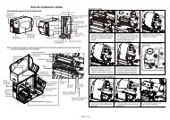
1. Open the lower front panel and the printer right side cover.<br />
54
<strong>TTP</strong>-<strong>246M</strong>/<strong>344M</strong> <strong>Bar</strong> <strong>Code</strong> <strong>Printer</strong><br />
<strong>Service</strong> <strong>Manual</strong><br />
2. There is a notch near by the platen roller bearing.<br />
Notch for peel off<br />
roller left side bush<br />
Notch for peel off roller<br />
right side bush<br />
3. Insert the peel off roller left side bush to the notch at the middle plate and insert the peel<br />
off roller right side bush to the notch at the right frame. Please refer to the magnified left<br />
and right side bush location for installation.<br />
55
<strong>TTP</strong>-<strong>246M</strong>/<strong>344M</strong> <strong>Bar</strong> <strong>Code</strong> <strong>Printer</strong><br />
<strong>Service</strong> <strong>Manual</strong><br />
Insert the left<br />
side first.<br />
Left side<br />
Right side<br />
Bush location<br />
Bush location<br />
56
<strong>TTP</strong>-<strong>246M</strong>/<strong>344M</strong> <strong>Bar</strong> <strong>Code</strong> <strong>Printer</strong><br />
<strong>Service</strong> <strong>Manual</strong><br />
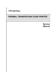
4. Fasten the leaf springs and washers with screws to fix the left and right side bush.<br />
Washer is placed<br />
between leaf spring<br />
and screw.<br />
57
<strong>TTP</strong>-<strong>246M</strong>/<strong>344M</strong> <strong>Bar</strong> <strong>Code</strong> <strong>Printer</strong><br />
<strong>Service</strong> <strong>Manual</strong><br />
Left side leaf spring<br />
Screw<br />
Right side leaf spring<br />
Screw<br />
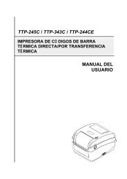
5. Hook the peel-off sensor on the bar which is near by the peel off sensor connector. Plug<br />
in the peel-off sensor assembly to the connector.<br />
Peel-off sensor<br />
assembly connector<br />
<strong>Bar</strong><br />
Print head pressure<br />
adjustment knob<br />
Peel-off sensor assembly<br />
58
<strong>TTP</strong>-<strong>246M</strong>/<strong>344M</strong> <strong>Bar</strong> <strong>Code</strong> <strong>Printer</strong><br />
<strong>Service</strong> <strong>Manual</strong><br />
Plug in the peel-off<br />
sensor assembly to<br />
the connector.<br />
59
<strong>TTP</strong>-<strong>246M</strong>/<strong>344M</strong> <strong>Bar</strong> <strong>Code</strong> <strong>Printer</strong><br />
<strong>Service</strong> <strong>Manual</strong><br />
4.17 Loading Label For Peel-off Mode<br />
1. Open the Print Head Lift Lever. The message “CARRIAGE OPEN” will be shown on the<br />
LCD screen, and the RED LED is on. The LCD panel shown as below.<br />
Print Head Lift<br />
Lever<br />
2. Remove the first one label from the liner. Insert the liner into the gap between Platen and<br />
Peel-off roller.<br />
60
<strong>TTP</strong>-<strong>246M</strong>/<strong>344M</strong> <strong>Bar</strong> <strong>Code</strong> <strong>Printer</strong><br />
<strong>Service</strong> <strong>Manual</strong><br />
Liner<br />
Peel-off roller<br />
3. Press the button (MENU, SELECT) under the message “Fwd.” to feed the label forward a<br />
little bit. Press the button (PAUSE, EXE./INC.) under the message “Rev.” to reverse the<br />
label if it is necessary for adjusting the label. Pull the liner outward tightly. Close the Print<br />
Head Lift Lever.<br />
Label<br />
Liner<br />
4. Close the lower front panel. Pull the label through the Peel-off panel upper opening; pull the<br />
liner through the Peel-off panel upper opening.<br />
61
<strong>TTP</strong>-<strong>246M</strong>/<strong>344M</strong> <strong>Bar</strong> <strong>Code</strong> <strong>Printer</strong><br />
<strong>Service</strong> <strong>Manual</strong><br />
Label<br />
Liner<br />
62
<strong>TTP</strong>-<strong>246M</strong>/<strong>344M</strong> <strong>Bar</strong> <strong>Code</strong> <strong>Printer</strong><br />
<strong>Service</strong> <strong>Manual</strong><br />
4.18 Cutter Module Installation (Option)<br />
1. Remove the 2 screws of the peel-off panel and uninstall the peel-off panel if it is<br />
installed in the front panel.<br />
2. Plug the mini DIN cable into the socket of the cutter connector.<br />
3. Install the cutter module.<br />
Notice : The cutter module bracket should be mounted into the slots.<br />
4. Fix the cutter module onto the printer cutter mount with a screw.<br />
5. Install the Cutter Module Panel with 2 screws to the front panel.<br />
Cutter Module<br />
Mini Din Cable<br />
Screw<br />
Slots<br />
Cutter Module<br />
Panel<br />
Lower Front<br />
panel<br />
63
<strong>TTP</strong>-<strong>246M</strong>/<strong>344M</strong> <strong>Bar</strong> <strong>Code</strong> <strong>Printer</strong><br />
<strong>Service</strong> <strong>Manual</strong><br />
5. POWER ON UTILITIES<br />
5.1 Calibrate Gap/Black Mark Sensor<br />
1. Gap/Black Mark Sensor Calibration<br />
This utility is used to calibrate the sensitivity of the gap/black mark sensor. The<br />
gap/black mark sensor should be calibrated whenever changing the label media or<br />
executing printer initialization.<br />
Please follow the steps below to calibrate the gap sensor.<br />
a. Install the ribbon and label media as the above-mentioned procedures, and<br />
engage the print head lift lever.<br />
b. Hold down the MENU button to scroll the cursor to the item “2. Sensor Calib.”<br />
And then press the EXE/INC button to execute gap sensor calibration utility.<br />
5.2 Self-test<br />
To initiate the self-test mode, depress the MENU button. Press MENU button to scroll<br />
the cursor to <strong>Printer</strong> test. Press EXE button to enter the submenu and press MENU<br />
button to “<strong>Printer</strong> Config”. Item. Press EXE button to print printer internal setting. In<br />
self-test, a check pattern is used to check the performance of the print head. Following<br />
the check pattern, the printer prints internal settings as listed below:<br />
1. <strong>Printer</strong> model and firmware version<br />
2. Check sum<br />
3. Serial port setting<br />
4. <strong>Code</strong> page setting<br />
5. Country code setting<br />
6. Print speed setting<br />
7. Print density setting<br />
8. Label size setting<br />
9. Gap (Bline) width and offset setting<br />
10. Backing paper transparence<br />
11. File list<br />
64
<strong>TTP</strong>-<strong>246M</strong>/<strong>344M</strong> <strong>Bar</strong> <strong>Code</strong> <strong>Printer</strong><br />
<strong>Service</strong> <strong>Manual</strong><br />
12. Memory available<br />
5.3 <strong>Printer</strong> Initialization<br />
<strong>Printer</strong> Initialization will restore printer settings to defaults.<br />
Default settings are listed as below.<br />
Item<br />
Default Value<br />
65<br />
Cleared by<br />
Initialization<br />
Property Saved<br />
when Turning off<br />
Power<br />
Mileage N/A No Yes<br />
Check Sum N/A No Yes<br />
Serial Port 9600,n,8,1 Yes Yes<br />
<strong>Code</strong> Page 437 Yes Yes<br />
Country <strong>Code</strong> 001 Yes Yes<br />
Tear Mode On Yes Yes<br />
Peel Mode Off Yes Yes<br />
Cutter Mode Off Yes Yes<br />
Offset 0 Yes Yes<br />
Reference Point 0,0 Yes Yes<br />
Print Direction 1 Yes Yes<br />
Speed 4 inch/sec Yes Yes<br />
Density 07 Yes Yes<br />
Label Size 4 x 2.5” Yes Yes<br />
Gap/Bline Sensor Gap Sensor Yes Yes<br />
Gap(Bline) 0.12” (3 mm) Yes Yes<br />
Transparency<br />
Ribbon Sensor<br />
Sensitivity<br />
Will be reset. Need<br />
to re-calibrate the<br />
gap sensor<br />
Yes<br />
Yes<br />
1 Yes Yes<br />
LCD Language English Yes Yes
<strong>TTP</strong>-<strong>246M</strong>/<strong>344M</strong> <strong>Bar</strong> <strong>Code</strong> <strong>Printer</strong><br />
<strong>Service</strong> <strong>Manual</strong><br />
Aux. LED Off Yes Yes<br />
Aux. Buzzer Off Yes Yes<br />
Download Files N/A No Yes<br />
RTC N/A No No<br />
Please follow the steps below to initialize the printer:<br />
1. Turn off the printer power.<br />
2. Hold down the PAUSE and FEED buttons and turn on the printer power.<br />
3. Do not release the buttons until the Red LEDs flash in turn.<br />
Note 1 : Printing method (thermal transfer or thermal direct printing ) will be set<br />
automatically at the activation of printer power.<br />
Note 2 : When printer initialization is done, please calibrate the gap sensor again.<br />
66
<strong>TTP</strong>-<strong>246M</strong>/<strong>344M</strong> <strong>Bar</strong> <strong>Code</strong> <strong>Printer</strong><br />
<strong>Service</strong> <strong>Manual</strong><br />
6. TROUBLESHOOTING<br />
The following guide lists the most common problems that may be encountered when<br />
operating this bar code printer. If the printer still does not function after all suggested<br />
solutions have been invoked, please contact the Customer <strong>Service</strong> Department of your<br />
purchased reseller or distributor for assistance.<br />
Phenomenon Cause of Errors Recovery Procedure<br />
No ribbon<br />
No paper<br />
Poor printing quality<br />
Power indicator does<br />
not illuminate<br />
Paper jam<br />
1. Running out of ribbon<br />
2. The ribbon is installed<br />
incorrectly.<br />
3. The ribbon sensor is not<br />
been well calibrated.<br />
1. Supply a new ribbon roll.<br />
2. Please refer to the steps in<br />
user’s manual to reinstall<br />
the ribbon.<br />
3. Please calibrate the ribbon<br />
sensor<br />
1. Running out of label 1. Supply a new label roll.<br />
2. The label is installed 2. Please refer to the steps in<br />
incorrectly.<br />
user’s manual to reinstall<br />
3. The moveable gap/black the label roll.<br />
mark sensor is not placed 3. Please move the sensor to<br />
in the proper location. the proper location.<br />
1. Dirt is accumulated on the 1. Please refer to the steps in<br />
print head.<br />
user’s manual to clear the<br />
2. The density setting is not print head.<br />
set properly<br />
2. Adjust the print density and<br />
3. Ribbon and media are speed.<br />
incompatible.<br />
3. Change proper ribbon or<br />
4. The pressure of print head proper label roll.<br />
is not set properly 4. Adjust the print head<br />
pressure adjustment knob.<br />
1. The power cord is not<br />
properly connected.<br />
1. The label size is not set<br />
properly.<br />
1. Please check whether the<br />
power cord is well<br />
connected between printer<br />
and outlet.<br />
1. a. Reset the label size.<br />
b. Re-calibrate the<br />
67
<strong>TTP</strong>-<strong>246M</strong>/<strong>344M</strong> <strong>Bar</strong> <strong>Code</strong> <strong>Printer</strong><br />
<strong>Service</strong> <strong>Manual</strong><br />
2. Labels may be stuck in<br />
side print mechanism.<br />
gap/black mark sensor.<br />
2. Remove the stuck label.<br />
Carriage open The printer carriage is open. Please close the print carriage.<br />
Memory full<br />
( FLASH / DRAM )<br />
No printout printing<br />
through serial port<br />
The space of FLASH/DRAM<br />
is full.<br />
1. The serial port setting is<br />
not consistent between<br />
host and printer.<br />
2. The serial port cable pin<br />
configuration is not pin to<br />
pin assignment.<br />
Delete unused files in the<br />
FLASH/DRAM.<br />
1. Please reset the serial port<br />
setting.<br />
2. Please replace the cable<br />
with pin to pin assignment.<br />
68
<strong>TTP</strong>-<strong>246M</strong>/<strong>344M</strong> <strong>Bar</strong> <strong>Code</strong> <strong>Printer</strong><br />
<strong>Service</strong> <strong>Manual</strong><br />
7. MAINTENANCE<br />
This session presents the clean tools and methods to maintain your printer.<br />
Use one or more of the following supplies that meets your needs:<br />
• Cleaning pens<br />
• Cleaning swabs<br />
• Lint-free cloth.<br />
The cleaning process is described as following<br />
<strong>Printer</strong> Part<br />
Method<br />
*<strong>Printer</strong> Head • Let the print head to cool for one minute<br />
• Use a cotton swab and 100% ethanol to clean<br />
the print head surface.<br />
Platen Roller • Rotate the platen roller and wipe it thoroughly<br />
with 100% ethanol and a cleaning swab, or<br />
lint-free cloth.<br />
Exterior • Wipe it with water-dampened cloth<br />
Interior • Brush or air blow<br />
Note:<br />
* Do not touch printer head by hand. If you touch it careless, please use ethanol to clean it.<br />
*It’s industry alcohol. Please do not use regular alcohol, which may damage the printer head.<br />
69
<strong>TTP</strong>-<strong>246M</strong>/<strong>344M</strong> <strong>Bar</strong> <strong>Code</strong> <strong>Printer</strong><br />
<strong>Service</strong> <strong>Manual</strong><br />
UPDATE HISTORY<br />
Date Content Editor<br />
2006/3/28 1. Modify to RoHS version. Camille<br />
2006/6/9 1.Modify the 5-3 item 8 : Main board ass’y from<br />
Camille<br />
98-0220085-00LF to 98-0220085-10LF<br />
2.Modify the 3-9 parallel port circuit figure<br />
2006/8/28 1. Add 5-3 item 11 : External Ethernet print server (Z) Camille<br />
2007/1/17 1. Add 5-3 item 11 : External wireless print<br />
server/US© and External wireless print server© (C)<br />
2. Add 5-3 item 12 : Cutter driver IC A3952SB<br />
(Non-RoHS)<br />
Camille<br />
2007/3/8 1. Add 5-2 item 12 : Media guide bar part number Camille<br />
2007/3/9 1. Modify 5-3 item 11 : External Ethernet print s© er<br />
(C) part no.<br />
Camille<br />
2007/4/12 1. Modify 5-2 accessible parts ll drawing Camille<br />
2007/4/14 1. Update <strong>TSC</strong> e-mail address Camille<br />
2007/5/31 1. Update printer Initialization section Camille<br />
2007/6/13 1. Update Power supply unit part no. from<br />
62-0180001-00LF to 62-0180001-10LF<br />
2007/7/19 1. Add cutter off and peeler Mini-DIN connector pin<br />
assignment<br />
Camille<br />
Camille<br />
2007/8/1 1. Company information update Camille<br />
2008/1/23 1. Modify description for 98-0220077-00LF Internal<br />
Ethernet print server (T), 98-0220078-00LF<br />
Internal Ethernet prin© erver (C) and<br />
98-0220079-00LF Internal wireless p© t server (C)<br />
2. Revoke part number for 98-1000017-00LF<br />
External Ethernet print server (Z)/US &<br />
98-1000018-00LF External Ethernet print server<br />
(Z)/EU (parallel port)<br />
3. Modify description for 98-1000008-00LF External<br />
Camille<br />
70
<strong>TTP</strong>-<strong>246M</strong>/<strong>344M</strong> <strong>Bar</strong> <strong>Code</strong> <strong>Printer</strong><br />
<strong>Service</strong> <strong>Manual</strong><br />
Etherne© rint server (C)/US, 98-1000009-00LF<br />
External Ethe© t print server (C)/EU,<br />
98-1000019-00LF External Ethernet print server<br />
(Z)/US, 98-1000020-00LF External Ethernet print<br />
server (Z)/EU, 98-1000011-00LF External w© less<br />
print server (C)/US and 98-1000012-00LF<br />
Externa© ireless print server (C)/EU<br />
2008/6/30 Remove the parts list section Camille<br />
2011/1/25 Modify <strong>TSC</strong> address Camille<br />
71
<strong>TSC</strong> Auto ID Technology Co., Ltd.<br />
Corporate Headquarters<br />
Li Ze Plant<br />
9F., No.95, Minquan Rd., Xindian Dist., No.35, Sec. 2, Ligong 1st Rd., Wujie Township,<br />
New Taipei City 23141, Taiwan (R.O.C.) Yilan County 26841, Taiwan (R.O.C.)<br />
TEL: +886-2-2218-6789 TEL: +886-3-990-6677<br />
FAX: +886-2-2218-5678 FAX: +886-3-990-5577<br />
Web site: www.tscprinters.com<br />
E-mail: printer_sales@tscprinters.com<br />
tech_support@tscprinters.com<br />
72