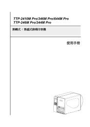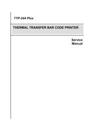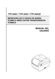
TTP-384M Bar Code Printer Service Manual - TSC
TTP-384M Bar Code Printer Service Manual - TSC
TTP-384M Bar Code Printer Service Manual - TSC

You also want an ePaper? Increase the reach of your titles
YUMPU automatically turns print PDFs into web optimized ePapers that Google loves.
<strong>TTP</strong>-<strong>384M</strong><br />
THERMAL TRANSFER / DIRECT THERMAL<br />
BAR CODE PRINTER<br />
SERVICE<br />
MANUAL
<strong>TTP</strong>-<strong>384M</strong><br />
<strong>Bar</strong> <strong>Code</strong> <strong>Printer</strong> <strong>Service</strong> <strong>Manual</strong><br />
TABLE OF CONTENT<br />
1. FUNDAMENTAL OF THE SYSTEM .......................................................................... 1<br />
1.1. Overview ................................................................................................................. 1<br />
2. ELECTRONICS .......................................................................................................... 5<br />
2.1 Summary of Board Connectors ............................................................................. 5<br />
2.2 Pin Configuration .................................................................................................... 8<br />
3. MECHANISM ........................................................................................................... 11<br />
3.1 Remove Covers ..................................................................................................... 11<br />
3.2 Replacing the LCD Panel Module ........................................................................ 13<br />
3.3 Replacing the Power Supply Unit ........................................................................ 14<br />
3.4 Replacing Multi-interface Board .......................................................................... 15<br />
3.5 Replacing the Main Board .................................................................................... 16<br />
3.6 Replacing the Platen Roller Assembly ................................................................ 17<br />
3.7 Replacing the Stepping Motor ............................................................................. 18<br />
3.8 Replacing the Printhead ASS'Y ........................................................................... 19<br />
3.9 Replacing the Gap and Black-mark Sensor Module .......................................... 21<br />
3.10 Replacing the DC Motor ..................................................................................... 23<br />
4. TROUBLESHOOTING ............................................................................................. 25<br />
4.1 Common Problems ............................................................................................... 25<br />
5. MAINTENANCE ....................................................................................................... 29<br />
UPDATE HISTORY ...................................................................................................... 31<br />
i
<strong>TTP</strong>-<strong>384M</strong><br />
<strong>Bar</strong> <strong>Code</strong> <strong>Printer</strong> <strong>Service</strong> <strong>Manual</strong><br />
1. FUNDAMENTAL OF THE SYSTEM<br />
1.1. Overview<br />
Front View<br />
1<br />
2<br />
3<br />
4<br />
5<br />
6<br />
1. LED indicators<br />
2. LCD display<br />
3. Front panel buttons<br />
4. Paper exit chute<br />
5. <strong>Printer</strong> cover<br />
6. Cutter module (Optional)<br />
1
<strong>TTP</strong>-<strong>384M</strong><br />
<strong>Bar</strong> <strong>Code</strong> <strong>Printer</strong> <strong>Service</strong> <strong>Manual</strong><br />
Interior View<br />
1<br />
8<br />
2<br />
3<br />
9<br />
4<br />
5<br />
6<br />
7<br />
11<br />
10<br />
1. Ribbon rewind spindle<br />
2. Print head pressure adjustment knobs<br />
3. Printhead<br />
4. Ribbon sensor<br />
5. Media sensor<br />
6. Platen roller<br />
7. Printhead release lever<br />
8. Ribbon supply spindle<br />
9. Label supply spindle<br />
10. Media guide bar<br />
11. Label guide<br />
2
<strong>TTP</strong>-<strong>384M</strong><br />
<strong>Bar</strong> <strong>Code</strong> <strong>Printer</strong> <strong>Service</strong> <strong>Manual</strong><br />
Rear View<br />
1<br />
2<br />
3<br />
8<br />
6<br />
7<br />
4<br />
5<br />
9<br />
1. Fan-fold paper entrance chute<br />
2. Centronics interface<br />
3. USB interface<br />
4. RS-232C interface<br />
5. Power jack socket<br />
*6. SD card slot<br />
7. Ethernet interface<br />
8. PS/2 interface<br />
9. Power switch<br />
* Recommended SD card specification.<br />
SD card spec SD card capacity Approved SD card manufacturer<br />
V1.0, V1.1 128 MB SanDisk, Transcend<br />
V1.0, V1.1 256 MB SanDisk, Transcend, Panasonic<br />
V1.0, V1.1 512 MB SanDisk, Transcend, Panasonic<br />
V1.0, V1.1 1 GB SanDisk, Transcend, Panasonic<br />
V2.0 SDHC CLASS 4 4 GB<br />
V2.0 SDHC CLASS 6 4 GB SanDisk, Transcend, Panasonic<br />
V1.0, V1.1 microSD 128 MB Transcend, Panasonic<br />
3
<strong>TTP</strong>-<strong>384M</strong><br />
<strong>Bar</strong> <strong>Code</strong> <strong>Printer</strong> <strong>Service</strong> <strong>Manual</strong><br />
V1.0, V1.1 microSD 256 MB Transcend, Panasonic<br />
V1.0, V1.1 microSD 512 MB Panasonic<br />
V1.0, V1.1 microSD 1 GB Transcend, Panasonic<br />
V2.0 SDHC CLASS 4 microSD 4 GB Panasonic<br />
V2.0 SDHC CLASS 6 microSD 4 GB Transcend<br />
V1.0, V1.1 miniSD 128 MB Transcend, Panasonic<br />
V1.0, V1.1 miniSD 256 MB Transcend, Panasonic<br />
V1.0, V1.1 miniSD 512 MB Transcend, Panasonic<br />
V1.0, V1.1 miniSD 1 GB Transcend, Panasonic<br />
V2.0 SDHC CLASS 4 miniSD 4 GB Transcend<br />
V2.0 SDHC CLASS 6 miniSD 4 GB<br />
- The DOS FAT file system is supported for the SD card.<br />
- Folders/files stored in the SD card should be in the 8.3 filename format<br />
- The miniSD/microSD card to SD card slot adapter is required.<br />
4
<strong>TTP</strong>-<strong>384M</strong><br />
<strong>Bar</strong> <strong>Code</strong> <strong>Printer</strong> <strong>Service</strong> <strong>Manual</strong><br />
2. ELECTRONICS<br />
2.1 Summary of Board Connectors<br />
Main board<br />
4 5<br />
13<br />
1<br />
6 7<br />
14<br />
2<br />
15<br />
3<br />
16<br />
8<br />
9 10<br />
11 12<br />
Connector Description Remark<br />
1 Centronics port connector J8<br />
2 USB connector J5<br />
3 RS-232C connector J4<br />
4 Head open sensor connector TPH-OP<br />
5 LCD panel connector LCD-PANEL<br />
6 Multi-interface board connector J11<br />
7 Micro processor CPU<br />
5
<strong>TTP</strong>-<strong>384M</strong><br />
<strong>Bar</strong> <strong>Code</strong> <strong>Printer</strong> <strong>Service</strong> <strong>Manual</strong><br />
8 Gap sensor connector GAP/BM,BM1<br />
9 Ribbon sensor connector RIBBON<br />
10 Cutter/peel-off sensor connector CUT&PEEL<br />
11 RFID module connector EX_SIO<br />
12 Stepping motor connector JP14<br />
13 Ribbon encoder sensor connector JP3,JP5<br />
14 Power supply output (24V DC) connector CN3<br />
15 Power (24V DC) connector J6<br />
16 Printhead connector TPH_C,JP2<br />
Multi-interface board<br />
1<br />
2<br />
3<br />
4<br />
Connector Description Remark<br />
1 Main board connector<br />
2 SD card slot<br />
3 Ethernet RJ-45 connector<br />
4 PS/2 connector<br />
6
<strong>TTP</strong>-<strong>384M</strong><br />
<strong>Bar</strong> <strong>Code</strong> <strong>Printer</strong> <strong>Service</strong> <strong>Manual</strong><br />
GPIO with multi-interface board (Optional)<br />
6<br />
2<br />
1<br />
3<br />
4<br />
5<br />
Connector Description Remark<br />
1 GPIO connector<br />
2 Main board connector<br />
3 SD card slot<br />
4 Ethernet RJ-45 connector<br />
5 PS/2 connector<br />
6 GPIO power connector<br />
7
<strong>TTP</strong>-<strong>384M</strong><br />
<strong>Bar</strong> <strong>Code</strong> <strong>Printer</strong> <strong>Service</strong> <strong>Manual</strong><br />
2.2 Pin Configuration<br />
RS-232C<br />
PIN CONFIGURATION<br />
1 +5 V<br />
2 TXD<br />
3 RXD<br />
4 CTS<br />
5 GND<br />
6 RTS<br />
7 N/C<br />
8 RTS<br />
9 N/C<br />
USB<br />
PIN CONFIGURATION<br />
1 N/C<br />
2 D-<br />
3 D+<br />
4 GND<br />
Centronics<br />
Pin SPP Mode Nibble In/Out Function<br />
1 Strobe N/A In<br />
A low on this line indicates that there are valid data<br />
at the host. When this pin is de-asserted, the +ve<br />
clock edge should be used to shift the data into the<br />
device.<br />
2-9 Data 0-7 N/A In Data Bus. Single-directional.<br />
10 Ack N/A Out<br />
A low on this line indicates that there are valid data<br />
at the Device. When this pin is de-asserted, the +ve<br />
clock edge should be used to shift the data into the<br />
host.<br />
11 Busy N/A Out When in reverse direction, a high indicates data,<br />
8
<strong>TTP</strong>-<strong>384M</strong><br />
<strong>Bar</strong> <strong>Code</strong> <strong>Printer</strong> <strong>Service</strong> <strong>Manual</strong><br />
while a low indicates a command cycle. In forward<br />
direction, it functions as PtrBusy.<br />
12<br />
Paper Out /<br />
End<br />
N/A Out When low, device acknowledges reverse request.<br />
13 Select N/A Out Extensibility flag<br />
14 Ground N/A GND<br />
15 No Defined N/A N/A<br />
16-17 Ground N/A GND Ground<br />
18 No Defined N/A N/A<br />
19-30 Ground N/A GND Ground<br />
31 No Defined N/A N/A<br />
32 Error / Fault N/A Out<br />
A low set by the device indicates that the reverse<br />
data is available<br />
33-35 Ground N/A GND Ground<br />
36 No Defined N/A N/A<br />
Ethernet<br />
PIN CONFIGURATION<br />
1 Tx+<br />
2 Tx-<br />
3 Rx+<br />
4 N/C<br />
5 N/C<br />
6 Rx-<br />
7 N/C<br />
8 N/C<br />
PS/2<br />
PIN CONFIGURATION<br />
1 KBD Clock<br />
2 GND<br />
3 KBD Data<br />
4 N/C<br />
5 +5V(VCC)<br />
6 N/C<br />
9
<strong>TTP</strong>-<strong>384M</strong><br />
<strong>Bar</strong> <strong>Code</strong> <strong>Printer</strong> <strong>Service</strong> <strong>Manual</strong><br />
GPIO<br />
10
<strong>TTP</strong>-<strong>384M</strong><br />
<strong>Bar</strong> <strong>Code</strong> <strong>Printer</strong> <strong>Service</strong> <strong>Manual</strong><br />
3. MECHANISM<br />
3.1 Remove Covers<br />
1. Remove 4 screws from printer.<br />
Screws<br />
Electronics<br />
cover<br />
2. Open printer right side cover and remove 2 screws then close the cover.<br />
Screws<br />
3. Remove the electronics cover.<br />
4. Remove 3 screws from each hinge. Be careful the right side cover may fall out from the<br />
printer. Take out the right side cover from the printer.<br />
Screws<br />
11<br />
Right side cover
<strong>TTP</strong>-<strong>384M</strong><br />
<strong>Bar</strong> <strong>Code</strong> <strong>Printer</strong> <strong>Service</strong> <strong>Manual</strong><br />
5. Reassemble the parts in the reverse procedures.<br />
12
<strong>TTP</strong>-<strong>384M</strong><br />
<strong>Bar</strong> <strong>Code</strong> <strong>Printer</strong> <strong>Service</strong> <strong>Manual</strong><br />
3.2 Replacing the LCD Panel Module<br />
1. Refer to section 3.1 to remove the electronics cover.<br />
2. Disconnect harness from the LCD panel module.<br />
3. Push two tabs to remove/replace the LCD panel module.<br />
PUSH<br />
Harness<br />
LCD panel<br />
module<br />
PUSH<br />
4. Remove 5 screws to replace LCD panel PCB ASS'Y and LCD panel ASS'Y.<br />
LCD panel PCB assembly<br />
5. Reassemble the parts in the reverse procedures.<br />
13
<strong>TTP</strong>-<strong>384M</strong><br />
<strong>Bar</strong> <strong>Code</strong> <strong>Printer</strong> <strong>Service</strong> <strong>Manual</strong><br />
3.3 Replacing the Power Supply Unit<br />
1. Refer to section 3.1 to remove the electronics cover.<br />
2. Disconnect 2 connectors and remove 2 screws on the power supply unit.<br />
---- Screw<br />
---- Connector<br />
3. Replace the power supply unit.<br />
4 . Reassemble the parts in the reverse procedures.<br />
14
<strong>TTP</strong>-<strong>384M</strong><br />
<strong>Bar</strong> <strong>Code</strong> <strong>Printer</strong> <strong>Service</strong> <strong>Manual</strong><br />
3.4 Replacing Multi-interface Board<br />
1. Refer to section 3.1 to remove the electronics cover.<br />
2. Remove 4 screws then take off the interface plate.<br />
Screws<br />
Interface<br />
plate<br />
3. Remove 2 screws.<br />
Screws<br />
4. Replace the multi-interface board.<br />
Copper pillar<br />
Connector<br />
Multi-interface<br />
board<br />
Copper pillar<br />
5. Reassemble the parts in the reverse procedures.<br />
15
<strong>TTP</strong>-<strong>384M</strong><br />
<strong>Bar</strong> <strong>Code</strong> <strong>Printer</strong> <strong>Service</strong> <strong>Manual</strong><br />
3.5 Replacing the Main Board<br />
1. Refer to section 3.1 and 3.4 to remove electronics cover and multi-interface board.<br />
2. Disconnect all connectors from the main board.<br />
3. Remove 2 copper pillars and 3 screws.<br />
Copper pillars<br />
Screws<br />
4. Replace the main board.<br />
5. Reassemble the parts in the reverse procedures.<br />
16
<strong>TTP</strong>-<strong>384M</strong><br />
<strong>Bar</strong> <strong>Code</strong> <strong>Printer</strong> <strong>Service</strong> <strong>Manual</strong><br />
3.6 Replacing the Platen Roller Assembly<br />
1. Open printer right side cover.<br />
2. Disengage print head lift lever.<br />
3. Remove the cutter module or lower front panel.<br />
4. Remove 4 screws from the platen holder.<br />
Screws<br />
Screws<br />
5. Take out the platen holder, platen roller assembly and replace a new platen roller<br />
assembly.<br />
Platen roller assembly<br />
Holder<br />
6. Reassemble the parts in the reverse procedures.<br />
17
<strong>TTP</strong>-<strong>384M</strong><br />
<strong>Bar</strong> <strong>Code</strong> <strong>Printer</strong> <strong>Service</strong> <strong>Manual</strong><br />
3.7 Replacing the Stepping Motor<br />
1. Refer to section 3.1 to remove the electronics cover.<br />
2. Disconnect the stepping motor connector from the main board.<br />
Stepping motor<br />
connector<br />
3. Remove 3 screws on the stepping motor.<br />
Screws<br />
4. Replace the stepping motor.<br />
5. Reassemble the parts in the reverse procedures.<br />
18
<strong>TTP</strong>-<strong>384M</strong><br />
<strong>Bar</strong> <strong>Code</strong> <strong>Printer</strong> <strong>Service</strong> <strong>Manual</strong><br />
3.8 Replacing the Printhead ASS'Y<br />
1. Open the printer right side cover.<br />
2. Disengage printhead release lever.<br />
3. Remove 2 screws from the mechanism.<br />
Screws<br />
4. Carefully disconnect 3 connectors from the printhead ASS'Y.<br />
5. Replace the printhead ASS'Y.<br />
19
<strong>TTP</strong>-<strong>384M</strong><br />
<strong>Bar</strong> <strong>Code</strong> <strong>Printer</strong> <strong>Service</strong> <strong>Manual</strong><br />
Printhead<br />
ASS'Y<br />
6. Connect the printhead cable and carefully slide assembly into the print mechanism. The<br />
holes of printhead assembly must align and then insert the tenons of print mechanism.<br />
Printhead<br />
ASS'Y<br />
Tenons<br />
Print mechanism<br />
7. Reassemble the parts in the reverse procedures.<br />
20
<strong>TTP</strong>-<strong>384M</strong><br />
<strong>Bar</strong> <strong>Code</strong> <strong>Printer</strong> <strong>Service</strong> <strong>Manual</strong><br />
3.9 Replacing the Gap and Black-mark Sensor Module<br />
1. Open the printer right side cover.<br />
2. Disengage printhead release lever.<br />
3. Refer to section 3.1 and 3.4 to remove electronics cover and multi-interface board.<br />
4. Disconnect the gap and black-mark sensor connectors from the main board.<br />
Gap sensor module<br />
connector<br />
Black-mark sensor<br />
module connector<br />
5. Remove 5 screws to take off the lower printhead mechanism.<br />
Screws<br />
Screws<br />
Lower printhead<br />
mechanism<br />
21
<strong>TTP</strong>-<strong>384M</strong><br />
<strong>Bar</strong> <strong>Code</strong> <strong>Printer</strong> <strong>Service</strong> <strong>Manual</strong><br />
6. Replace the sensor module.<br />
7. Reassemble the parts in the reverse procedures.<br />
22
<strong>TTP</strong>-<strong>384M</strong><br />
<strong>Bar</strong> <strong>Code</strong> <strong>Printer</strong> <strong>Service</strong> <strong>Manual</strong><br />
3.10 Replacing the DC Motor<br />
1. Refer to section 3.1 to remove the electronics cover.<br />
2. Disconnect the DC motor connectors from the main board.<br />
DC motor connectors<br />
3. Remove 3 screws at the DC motor fixing plate.<br />
Screws<br />
4. Remove the DC motors by removing the 6 screws.<br />
Screws<br />
Screws<br />
5. Replace the DC motors.<br />
6. Reassemble the parts in the reverse procedures.<br />
23
<strong>TTP</strong>-<strong>384M</strong><br />
<strong>Bar</strong> <strong>Code</strong> <strong>Printer</strong> <strong>Service</strong> <strong>Manual</strong><br />
4. TROUBLESHOOTING<br />
4.1 Common Problems<br />
The following guide lists the most common problems that might be encountered when<br />
operating this bar code printer. If the printer still does not function after all suggested<br />
solutions have been invoked, please contact the Customer <strong>Service</strong> Department of your<br />
purchased reseller or distributor for assistance.<br />
Problem Possible Cause Recovery Procedure<br />
Power indicator does<br />
not illuminate<br />
* The power cord is not properly<br />
connected.<br />
* Plug the power cord in printer and outlet.<br />
* Switch the printer on.<br />
Carriage Open<br />
* The printer carriage is open. * Please close the print carriage.<br />
No Ribbon<br />
* Running out of ribbon.<br />
* The ribbon is installed incorrectly.<br />
* Supply a new ribbon roll.<br />
* Please refer to the steps in user’s manual to<br />
reinstall the ribbon.<br />
No Paper<br />
* Running out of label.<br />
* The label is installed incorrectly.<br />
* Gap/black-mark sensor is not<br />
calibrated.<br />
* Supply a new label roll.<br />
* Please refer to the steps in user’s manual to<br />
reinstall the label roll.<br />
* Calibrate the gap/black-mark sensor.<br />
Paper Jam<br />
* Gap/black-mark sensor is not set<br />
properly.<br />
* Make sure label size is set properly.<br />
* Labels may be stuck inside the printer<br />
mechanism.<br />
* Calibrate the gap/black-mark sensor.<br />
* Set label size correctly.<br />
UP:<br />
DOWN:<br />
MENU:<br />
Fwd.<br />
Rev.<br />
Exit<br />
* Cutter jam.<br />
* There is no cutter installed on the<br />
printer.<br />
* Cutter PCB is damaged.<br />
* If the cutter module is installed, please press UP<br />
or DOWN key to rotate the cutter up or down to<br />
make the knife back to the right position.<br />
* Remove the label.<br />
* Make sure the thickness of label is less than<br />
0.254 mm (10mil)<br />
* Replace a cutter PCB.<br />
25
<strong>TTP</strong>-<strong>384M</strong><br />
<strong>Bar</strong> <strong>Code</strong> <strong>Printer</strong> <strong>Service</strong> <strong>Manual</strong><br />
Not Printing<br />
Memory full<br />
( FLASH / DRAM )<br />
SD card is unable to<br />
use<br />
PS/2 port does not<br />
work<br />
* Cable is not well connected to serial or<br />
USB interface or parallel port.<br />
* The serial port cable pin configuration<br />
is not pin to pin connected.<br />
* The space of FLASH/DRAM is full.<br />
* SD card is damaged.<br />
* SD card doesn’t insert correctly.<br />
* Use the non-approved SD card<br />
manufacturer.<br />
* Did not turn off power prior to plug in<br />
the PS/2 keyboard.<br />
* PS/2 keyboard is damaged.<br />
* PS/2 keyboard doesn’t plug-in<br />
correctly.<br />
* There is no BAS file in the printer.<br />
* Re-connect cable to interface.<br />
* If using serial cable,<br />
- Please replace the cable with pin to pin<br />
connected.<br />
- Check the baud rate setting. The default baud<br />
rate setting of printer is 9600,n,8,1.<br />
* If using the Ethernet cable,<br />
- Check if the Ethernet RJ-45 connector green<br />
LED is lit on..<br />
- Check if the Ethernet RJ-45 connector amber<br />
LED is blinking.<br />
- Check if the printer gets the IP address when<br />
using DHCP mode.<br />
- Check if the IP address is correct when using<br />
the static IP address.<br />
- Wait a few seconds let the printer get the<br />
communication with the server then check the<br />
IP address setting again.<br />
* Chang a new cable.<br />
* Ribbon and media are not compatible.<br />
* Verify the ribbon-inked side.<br />
* Reload the ribbon again.<br />
* Clean the printhead.<br />
* The print density setting is incorrect.<br />
* Printhead’s harness connector is not well<br />
connected with printheat. Turn off the printer<br />
and plug the connector again.<br />
* Check if the stepping motor is plugging in the<br />
right connector.<br />
* Check your program if there is a command<br />
PRINT at the end of the file and there must have<br />
CRLF at the end of each command line.<br />
* Delete unused files in the FLASH/DRAM.<br />
* The max. numbers of file of DRAM is 256 files.<br />
* The max. user addressable memory space of<br />
DRAM is 2048 KB.<br />
* The max. numbers of file of FLASH is 256 files.<br />
* The max. user addressable memory space of<br />
FLASH is 6656KB.<br />
* Use the supported capacity SD card.<br />
* Insert the SD card again.<br />
* The supported SD card spec.<br />
- 128MB<br />
- 256MB<br />
- 512MB<br />
- 1GB<br />
- 4GB SDHC CLASS 6<br />
* Approved SD card manufacturers; SanDisk,<br />
Transcend<br />
* Turn off printer power prior to plug in the PS/2<br />
keyboard .<br />
* Plug the PS/2 keyboard again.<br />
* Make sure the keyboard is fine.<br />
* Make sure if there is any BAS file downloaded<br />
into printer.<br />
26
<strong>TTP</strong>-<strong>384M</strong><br />
<strong>Bar</strong> <strong>Code</strong> <strong>Printer</strong> <strong>Service</strong> <strong>Manual</strong><br />
Poor Print Quality<br />
LCD panel is dark and<br />
keys are not working<br />
LCD panel is dark but<br />
the LEDs are light<br />
LCD panel is dark and<br />
LEDs are lit on, but<br />
the label is feeding<br />
forward<br />
Ribbon encoder<br />
sensor doesn’t work<br />
Ribbon end sensor<br />
doesn’t work<br />
* Ribbon and media is loaded incorrectly<br />
* Dust or adhesive accumulation on the<br />
printhead.<br />
* Print density is not set properly.<br />
* Printhead element is damaged.<br />
* Ribbon and media are incompatible.<br />
* The printhead pressure is not set<br />
properly.<br />
* The cable between main PCB and LCD<br />
panel is loose.<br />
* The printer initialization is<br />
unsuccessful.<br />
* The LCD panel harness connector is<br />
loose.<br />
* The ribbon encoder sensor connector<br />
is loose.<br />
* Reload the supply.<br />
* Clean the printhead.<br />
* Clean the platen roller.<br />
* Adjust the print density and print speed.<br />
* Run printer self-test and check the printhead<br />
test pattern if there is dot missing in the pattern.<br />
* Change proper ribbon or proper label media.<br />
* Adjust the printhead pressure adjustment knob.<br />
- If the left side printout is too light, please adjust<br />
the left side pressure adjustment knob to the<br />
higher index (higher pressure). If the pressure<br />
adjustment knob has been adjust to index “5”<br />
and the poor print quality is still at the left side<br />
of the printout, please adjust the pressure<br />
adjustment knob to index “1” and use the<br />
Z-axis adjustment knob to fine tune the<br />
pressure.<br />
- If the right side printout is too light, please<br />
adjust the right side pressure adjustment knob<br />
to the higher index (higher pressure) to<br />
improve the print quality.<br />
* If the label thickness is more than 0.22 mm, the<br />
print quality might be not good enough, please<br />
adjust the heater line adjustment screw counter<br />
clockwise to get the best print quality.<br />
* The release lever does not latch the printhead<br />
properly.<br />
* Check if the cable between main PCB and LCD<br />
is secured or not.<br />
* Turn OFF and ON the printer again.<br />
* Initialize the printer.<br />
* The LCD panel harness connector is plugged<br />
upside down.<br />
* Fasten the connector.<br />
* The connector is loose.<br />
* Check the connector.<br />
* The ribbon sensor hole is covered with<br />
* Clear the dust in the sensor hole by the blower.<br />
dust.<br />
Cutter is not working * The connector is loose.<br />
Label feeding is not<br />
stable (skew) when<br />
printing<br />
Skip labels when<br />
printing<br />
* The media guide does not touch the<br />
edge of the media.<br />
* Plug in the connect cable correctly.<br />
* If the label is moving to the right side, please<br />
move the label guide to left.<br />
* If the label is moving to the left side, please<br />
move the label guide to right.<br />
* Check if label size is setup correctly.<br />
* Label size is not specified properly.<br />
* Calibrate the sensor by Auto Gap or <strong>Manual</strong><br />
* Sensor sensitivity is not set properly.<br />
Gap options.<br />
* The media sensor is covered with dust.<br />
* Clear the GAP/Black-mark sensor by blower.<br />
27
<strong>TTP</strong>-<strong>384M</strong><br />
<strong>Bar</strong> <strong>Code</strong> <strong>Printer</strong> <strong>Service</strong> <strong>Manual</strong><br />
The left side printout<br />
position is incorrect<br />
Missing printing on<br />
* Set the correct label size.<br />
* Wrong label size setup.<br />
* Press [MENU] [SELECT] x 3 [DOWN] x 5<br />
* The parameter Shift X in LCD menu is<br />
[SELECT] to fine tune the parameter of Shift<br />
incorrect.<br />
X.<br />
the left or right side of * Wrong label size setup. * Set the correct label size.<br />
label<br />
RTC time is incorrect<br />
when reboot the<br />
printer<br />
Multi interface board<br />
doesn’t work<br />
* The battery has run down. * Check if there is a battery on the main board.<br />
* The installation is incorrect.<br />
Power and Error LEDs<br />
* Power switch OFF and ON too fast.<br />
are blinking fast<br />
Wrinkle Problem<br />
Gray line on the blank<br />
label<br />
Irregular printing<br />
* Printhead pressure is incorrect.<br />
* Ribbon installation is incorrect.<br />
* Media installation is incorrect.<br />
* Print density is incorrect.<br />
* Media feeding is incorrect.<br />
* The printhaed is dirty.<br />
* The platen roller is dirty.<br />
* The printer is in Hex Dump mode.<br />
* The RS-232 setting is incorrect.<br />
* Check if the board is plugged in the right<br />
connector.<br />
* Turn off the printer and wait all LEDs are dark,<br />
and turn on the printer again.<br />
* Make sure the label guide touch the edge of the<br />
media guide.<br />
* Make sure label, paper core and ribbon are set<br />
at the center of the spindle.<br />
* Clean the printhead.<br />
* Clean the platen roller.<br />
* Turn off and on the printer to skip the dump<br />
mode.<br />
* Re-set the Rs-232 setting.<br />
28
<strong>TTP</strong>-<strong>384M</strong><br />
<strong>Bar</strong> <strong>Code</strong> <strong>Printer</strong> <strong>Service</strong> <strong>Manual</strong><br />
5. MAINTENANCE<br />
This session presents the clean tools and methods to maintain your printer.<br />
1. Please use one of following material to clean the printer.<br />
• Cotton swab (Head cleaner pen)<br />
• Lint-free cloth<br />
• Vacuum / Blower brush<br />
• 100% ethanol<br />
2. The cleaning process is described as following<br />
<strong>Printer</strong> Part Method Interval<br />
1. Always turn off the printer Clean the print head when changing a<br />
before cleaning the print head. new label roll<br />
2. Allow the print head to cool for<br />
a minimum of one minute.<br />
3. Use a cotton swab (Head<br />
cleaner pen) and 100% ethanol<br />
to clean the print head surface.<br />
Print Head<br />
Platen Roller<br />
1. Turn the power off.<br />
2. Rotate the platen roller and<br />
wipe it thoroughly with 100%<br />
ethanol and a cotton swab, or<br />
lint-free cloth.<br />
29<br />
Clean the platen roller when changing<br />
a new label roll<br />
Sensor Compressed air or vacuum Monthly
<strong>TTP</strong>-<strong>384M</strong><br />
<strong>Bar</strong> <strong>Code</strong> <strong>Printer</strong> <strong>Service</strong> <strong>Manual</strong><br />
Wipe it with water-dampened As needed<br />
Exterior<br />
cloth<br />
Interior Brush or vacuum As needed<br />
Note:<br />
• Do not touch printer head by hand. If you touch it careless, please use ethanol to clean<br />
it.<br />
• Please use 100% Ethenol. DO NOT use medical alcohol, which may damage the printer<br />
head.<br />
• Regularly clean the print head and supply sensors once change a new ribbon to keep<br />
printer performance and extend printer life.<br />
30
<strong>TTP</strong>-<strong>384M</strong><br />
<strong>Bar</strong> <strong>Code</strong> <strong>Printer</strong> <strong>Service</strong> <strong>Manual</strong><br />
UPDATE HISTORY<br />
Date Content Editor<br />
2009/1/19 Modify section 3.8 (Replacing the printhead assembly) Camille<br />
2009/2/20 Modify section 3.8 (Replacing the printhead assembly) Camille<br />
2009/3/16 Modify section 1.1 (Recommended SD card specification) Camille<br />
2011/1/25 Modify <strong>TSC</strong> address Camille<br />
2011/4/8 Modify section 2.2 Camille<br />
2011/5/10 Add section 3.10 (Replacing the DC motor) Camille<br />
31
<strong>TSC</strong> Auto ID Technology Co., Ltd.<br />
Corporate Headquarters<br />
Li Ze Plant<br />
9F., No.95, Minquan Rd., Xindian Dist., No.35, Sec. 2, Ligong 1st Rd., Wujie Township,<br />
New Taipei City 23141, Taiwan (R.O.C.) Yilan County 26841, Taiwan (R.O.C.)<br />
TEL: +886-2-2218-6789 TEL: +886-3-990-6677<br />
FAX: +886-2-2218-5678 FAX: +886-3-990-5577<br />
Web site: www.tscprinters.com<br />
E-mail: printer_sales@tscprinters.com<br />
tech_support@tscprinters.com<br />
33