bubble pump modeling for solar hot water heater system design
bubble pump modeling for solar hot water heater system design bubble pump modeling for solar hot water heater system design
m L [kg/s] RESULTS & DISCUSSION To solve all of the non-linear equations, Engineering Equation Solver (EES) software is used. EES is an equation solver software that can iteratively solve thousands of linear or non-linear equations simultaneously. It has built in libraries for thermodynamic and fluid transport properties, thus it is widely used in the Mechanical Engineering field. It can also solve differential and integral equations, which is helpful for the optimization of parameters for the solar thermal bubble pump water heating systems. Mass Flow Rate VS Diameter 0.12 0.1 0.08 0.06 0.04 0.02 0 Pressure = 0.25 bars Pressure = 0.40 bars Pressure = 0.336 bars 0.01 0.02 0.03 0.04 0.05 0.06 0.07 0.08 D [m] Figure 7: Liquid Mass Flow Rate Versus Lift Tube Diameter for Varying System Pressure Conditions. 182
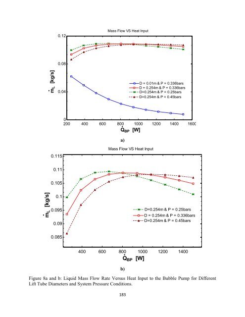
m L [kg/s] m L [kg/s] 0.12 Mass Flow VS Heat Input 0.08 0.04 D = 0.01m & P = 0.336bars D = 0.254m & P = 0.336bars D=0.254m & P = 0.25bars D=0.254m & P = 0.45bars 0 200 400 600 800 1000 1200 1400 1600 Q BP [W] a) 0.115 Mass Flow VS Heat Input 0.11 0.105 0.1 0.095 0.09 D=0.254m & P = 0.25bars D = 0.254m & P = 0.336bars D=0.254m & P = 0.45bars 0.085 400 600 800 1000 1200 1400 b) Figure 8a and b: Liquid Mass Flow Rate Versus Heat Input to the Bubble Pump for Different Lift Tube Diameters and System Pressure Conditions. 183 Q BP [W]
- Page 1 and 2: BUBBLE PUMP MODELING FOR SOLAR HOT
- Page 3 and 4: P Q Pressure (bars) Volumetric flow
- Page 5 and 6: Figure 1: US Energy Consumption by
- Page 7 and 8: Figure 3 : Thermosyphon Solar Hot W
- Page 9 and 10: METHODOLOGY Two-phase flow is the m
- Page 11 and 12: P 0 2 V0 Psys LgH L [1] 2 Where:
- Page 13 and 14: A L 1 [15] A 2 Now the momentum eq
- Page 15: [24a] [24b] Bubbly flow then occurs
- Page 19 and 20: fluctuates throughout the day, the
- Page 21: White, S.J., 2001. Bubble Pump Desi
m L [kg/s]<br />
m L [kg/s]<br />
0.12<br />
Mass Flow VS Heat Input<br />
0.08<br />
0.04<br />
D = 0.01m & P = 0.336bars<br />
D = 0.254m & P = 0.336bars<br />
D=0.254m & P = 0.25bars<br />
D=0.254m & P = 0.45bars<br />
0<br />
200 400 600 800 1000 1200 1400 1600<br />
Q BP [W]<br />
a)<br />
0.115<br />
Mass Flow VS Heat Input<br />
0.11<br />
0.105<br />
0.1<br />
0.095<br />
0.09<br />
D=0.254m & P = 0.25bars<br />
D = 0.254m & P = 0.336bars<br />
D=0.254m & P = 0.45bars<br />
0.085<br />
400 600 800 1000 1200 1400<br />
b)<br />
Figure 8a and b: Liquid Mass Flow Rate Versus Heat Input to the Bubble Pump <strong>for</strong> Different<br />
Lift Tube Diameters and System Pressure Conditions.<br />
183<br />
Q BP [W]


