Appendix 2G â Part 2: Power Distribution Cut Sheets
Appendix 2G â Part 2: Power Distribution Cut Sheets
Appendix 2G â Part 2: Power Distribution Cut Sheets

Create successful ePaper yourself
Turn your PDF publications into a flip-book with our unique Google optimized e-Paper software.
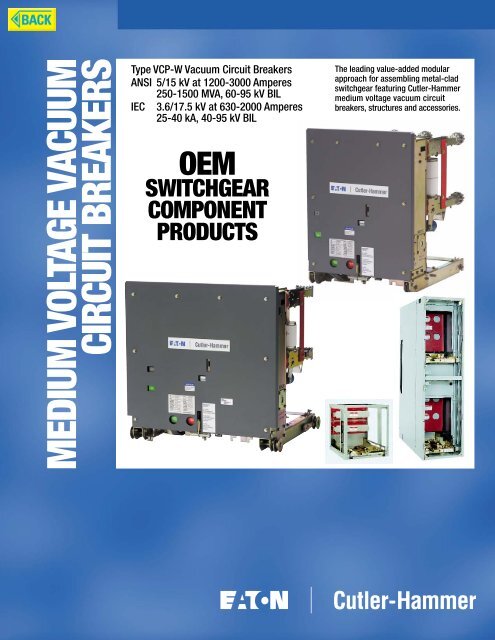
MEDIUM VOLTAGE VACUUM<br />
CIRCUIT BREAKERS<br />
Type VCP-W Vacuum Circuit Breakers<br />
ANSI 5/15 kV at 1200-3000 Amperes<br />
250-1500 MVA, 60-95 kV BIL<br />
IEC 3.6/17.5 kV at 630-2000 Amperes<br />
25-40 kA, 40-95 kV BIL<br />
OEM<br />
SWITCHGEAR<br />
COMPONENT<br />
PRODUCTS<br />
The leading value-added modular<br />
approach for assembling metal-clad<br />
switchgear featuring <strong>Cut</strong>ler-Hammer<br />
medium voltage vacuum circuit<br />
breakers, structures and accessories.
<strong>Cut</strong>ler-Hammer Products<br />
The Industry Leader<br />
in Vacuum Circuit Breakers<br />
VacClad-W, the <strong>Cut</strong>ler-Hammer vacuum<br />
switchgear family, has been engineered<br />
to feature a standardized design, interchangeable<br />
parts, slot and tab construction,<br />
and industry-leading vacuum interrupter<br />
technology. This world class switchgear<br />
includes the Type VCP-W Vacuum Circuit<br />
Breaker which meets both ANSI and IEC<br />
electrical standards.<br />
Industry-Leading Vacuum Technology<br />
Provides Unequaled Reliability<br />
<strong>Cut</strong>ler-Hammer now provides the industry’s<br />
most complete family of technologically<br />
advanced vacuum circuit breakers at 5 kV,<br />
15 kV, 27 kV, and 38 kV. Type VCP-W<br />
Vacuum Circuit Breakers incorporate many<br />
design features which have been field<br />
proven with more than 25 years of vacuum<br />
interrupter design and manufacturing<br />
experience…coupled with over 70 years<br />
of power circuit breaker design and manufacturing<br />
experience.<br />
Type VCP-W Vacuum Circuit Breakers are<br />
available in a complete range of ANSI and<br />
IEC ratings:<br />
ANSI<br />
IEC<br />
5 kV through 38 kV,<br />
continuous currents from<br />
600 through 3000 amperes.<br />
3.6 kV through 36 kV,<br />
continuous currents from<br />
630 through 2000 amperes.<br />
ISO Certified Facilities<br />
Type VCP-W Vacuum Circuit Breakers,<br />
including the vacuum interrupter, are assembled<br />
by <strong>Cut</strong>ler-Hammer in ISO 9002<br />
certified facilities. The breakers are fully<br />
tested to ANSI and IEC standards and<br />
each is provided with its unique Quality<br />
Assurance Certificate that documents all<br />
tests and inspections performed.<br />
Assembly Flexibility<br />
Assembly flexibility is provided with a<br />
variety of industry leading value-added<br />
approaches for assembling premier<br />
metal-clad switchgear. Customers have<br />
the unique opportunity to select the appropriate<br />
building block approach to match<br />
their manufacturing capabilities with those<br />
of <strong>Cut</strong>ler-Hammer.<br />
The OEM Value-Added Approach to Circuit Protection…<br />
Flexibility that Exceeds the Customer’s Requirements<br />
Type VCP-W Vacuum Circuit Breakers<br />
Industry Leading Vacuum Technology<br />
in ANSI 5/15 kV or IEC 3.6/17.5 kV<br />
■ Type VCP-W.<br />
■ Type VCPW-SE.<br />
■ Type VCPW-ND.<br />
<strong>Power</strong> Modules<br />
Complete Structures<br />
Including Fully Equipped Breaker<br />
Compartment and Auxiliary Provisions<br />
Mini Modules<br />
A Simple Building Block Approach<br />
Easily Configured to Any Project Specification<br />
Mini Modules Configured as:<br />
■ A One-High Fully Equipped Breaker<br />
Compartment for 1200, 2000,<br />
or 3000 Amperes.<br />
Circuit Breaker Compartment Kits<br />
Provide the Opportunity to Add the Most<br />
Value and Include All Key Breaker/Cell<br />
Interfacing <strong>Part</strong>s Necessary to Build<br />
a Breaker Compartment<br />
Auxiliary Drawer Compartment Kits<br />
All <strong>Part</strong>s Necessary for Building Potential<br />
Transformer, Control <strong>Power</strong> Transformer,<br />
or Fuse Drawer Compartments<br />
Tools and Accessories<br />
A Complete Selection of Standard<br />
and Optional Tools and Accessories<br />
2
<strong>Cut</strong>ler-Hammer 5/15 kV Medium Voltage Switchgear Components<br />
5/15 kV Medium Voltage Breaker<br />
Rating Chart<br />
ANSI Standards – Type VCP-W Vacuum Circuit Breaker Rated on Symmetrical Current Rating Basis➀<br />
Identification Rated Values Weight<br />
Circuit Nominal Nominal Voltage Insulation Level Current Interrupting Permissible Maximum Current Values<br />
Breaker Voltage 3-Phase<br />
Time➃ Tripping Voltage<br />
Type Class MVA<br />
Maximum Voltage Withstand Continuous Short<br />
Delay Divided<br />
Maximum Closing and Closing and<br />
Class<br />
Voltage Range Test Voltage Current Circuit<br />
by K<br />
Symmetrical Latching Latching<br />
Factor➂ at 60 Hz Current<br />
Interrupting Capability Capability<br />
(at Rated Capability Momentary<br />
<strong>Power</strong> Impulse<br />
Maximum kV)<br />
K Times 2.7 K 1.6 K<br />
Frequency Rated Short Times Rated Times Rated<br />
(1 Minute) Circuit Short Circuit Short Circuit<br />
Current➂ Current Current<br />
E K I Y E/K<br />
kV MVA kV rms kV rms kV Peak Amperes kA rms Cycles Seconds kV rms kA rms kA Peak kA rms lbs.<br />
50VCPW-ND250 4.16 250 4.76 1.24 19 60 1200 29 5 2 3.85 36 97 58 345<br />
50VCP-W250 4.16 250 4.76 1.24 19 60 1200 29 5 2 3.85 36 97 58 350<br />
2000 132➁ 78➁ 410<br />
3000 525<br />
50VCP-W350 4.16 350 4.76 1.19 19 60 1200 41 5 2 4.00 49 132 78 460<br />
2000 490<br />
3000 525<br />
75VCP-W500 7.2 500 8.25 1.25 36 95 1200 33 5 2 6.60 41 111 66 375<br />
2000 410<br />
3000 525<br />
150VCP-W500 13.8 500 15.00 1.30 36 95 1200 18 5 2 11.50 23 62 37 350<br />
2000 97➁ 58➁ 410<br />
3000 525<br />
150VCP-W750 13.8 750 15.00 1.30 36 95 1200 28 5 2 11.50 36 97 58 350<br />
2000 130➁ 77➁ 410<br />
3000 525<br />
150VCP-W1000 13.8 1000 15.00 1.30 36 95 1200 37 5 2 11.50 48 130 77 460<br />
2000 490<br />
3000 525<br />
150VCP-W1500 13.8 1500 15.00 1.00 36 95 1200 63 5 2 15.00 63 170 101 525<br />
2000 530<br />
3000 550<br />
IEC-56 Standards – Type VCP-W Vacuum Circuit Breaker Rated on Symmetrical Current Rating Basis➅<br />
Identification Rated Values Weight<br />
Circuit Voltage Insulation Level Normal Short Short Short Cable<br />
Breaker Class<br />
Current Circuit Time Circuit Charging<br />
Type<br />
<strong>Power</strong><br />
Impulse<br />
Breaking (3 Second) Making Breaking<br />
Frequency<br />
Withstand<br />
Current Current Current Current<br />
kV rms kV Peak kV Peak Amperes kA rms kA rms kA Peak Amperes kg<br />
36VCPW-ND25 3.6 10 40 630, 1250 25 25 63 25 159<br />
36VCPW-ND32 3.6 10 40 630, 1250 31.5 31.5 79 25 159<br />
72VCPW-ND25 7.2 20 60 630, 1250 25 25 63 25 159<br />
72VCPW-ND32 7.2 20 60 630, 1250 31.5 31.5 79 25 159<br />
36VCP-W25 3.6 10 40 630, 1250, 2000 25 25 63 25 188<br />
36VCP-W32 3.6 10 40 1250, 2000 31.5 31.5 79 25 188<br />
36VCP-W40 3.6 10 40 1250, 2000 40 40 100 25 225<br />
72VCP-W25 7.2 20 60 630, 1250, 2000 25 25 63 25 188<br />
72VCP-W32 7.2 20 60 1250, 2000 31.5 31.5 79 25 188<br />
72VCP-W40 7.2 20 60 1250, 2000 40 40 100 25 225<br />
120VCP-W25 12 28 75 630, 1250, 2000 25 25 63 25 195<br />
120VCP-W32 12 28 75 1250, 2000 31.5 31.5 79 25 195<br />
120VCP-W40 12 28 75 1250, 2000 40 40 100 25 225<br />
175VCP-W25 17.5 38 95 1250, 2000 25 25 63 31.5 195<br />
175VCP-W32 17.5 38 95 1250, 2000 31.5 31.5 79 31.5 195<br />
175VCP-W40 17.5 38 95 1250, 2000 40 40 100 31.5 225<br />
➀ Applicable ANSI standards C37.04 - 1979, C37.09 - 1979, and C37.06 -<br />
1987. Operating duty cycle CO-15 seconds-CO. Operating time values:<br />
opening 30-45 ms, closing 45-60 ms and reclosing 18 cycles (300 ms).<br />
➁ Nonstandard circuit breakers with High Close and Latch (momentary)<br />
rating for special applications.<br />
➂ Consult Application Data 32-265 for further information.<br />
➃ Optional interrupting time of 3 cycles is available.<br />
➄ Also 3 second short time current carrying capability.<br />
➅ Interrupting time is 3 cycles at 50/60 Hz. Rated operating sequence:<br />
O-3 minutes-CO-3 minutes-CO.<br />
11
<strong>Cut</strong>ler-Hammer Products<br />
Metering, Protection,<br />
and Communications<br />
<strong>Cut</strong>ler-Hammer <strong>Power</strong> Management Products<br />
provide the solutions to monitor and manage<br />
all aspects of an electrical distribution system.<br />
These innovative meters, relays and communications<br />
software applications make it<br />
possible to realize greater reliability, increased<br />
productivity and significant cost savings.<br />
METERS<br />
IQ Analyzer 6400/<br />
6600 Series<br />
The Premier <strong>Power</strong><br />
Quality Meter<br />
The IQ Analyzer provides<br />
comprehensive<br />
diagnostic capabilities<br />
with over 150 metered<br />
values. This device assists<br />
in preventing process<br />
disruptions and<br />
equipment damage by<br />
storing trends, analyzing<br />
harmonics and capturing waveforms. Historical<br />
data captured by the IQ Analyzer helps to identify<br />
problems in an electrical distribution system. Energy<br />
usage and costs are controllable through highly<br />
accurate energy measurement, on-board energy<br />
value storage and time-of-use energy registers.<br />
Optional graphical waveform and harmonic spectrum<br />
display available on the 6600 series.<br />
IQ DP-4000<br />
Metering and Voltage<br />
Protection<br />
The IQ DP-4000 provides<br />
complete electrical metering<br />
and system voltage<br />
protection. This device<br />
measures and displays<br />
over 74 electrical system<br />
values. It measures % total harmonic distortion<br />
(%THD) for both current and voltage to help find the<br />
source of problems. The IQ DP-4000 keeps track of<br />
total energy used along with the maximum demand<br />
to aid in energy management. Optional digital I/O<br />
available on the 4100 series.<br />
IQ 200<br />
Switchboard Metering<br />
The IQ 200 family is a group of<br />
revenue accurate ANSI<br />
C12.16 meters that provide big<br />
features in a small and flexible<br />
package. They are ideal for<br />
panelboard and switchboard applications where<br />
panel space is at a premium. Energy management<br />
information is provided by direct reading of metered<br />
values. With built-in communications the IQ 200<br />
base can be used as a metering transducer for<br />
submetering applications.<br />
10<br />
PROTECTIVE RELAYS<br />
MP-3000<br />
Award-Winning<br />
Motor Protection<br />
The MP-3000, winner<br />
of a Plant Engineering<br />
magazine Product of<br />
the Year award, protects<br />
three-phase induction<br />
motors of any<br />
size and voltage. Integral<br />
Intel-I-Trip <br />
overload protection<br />
develops protection<br />
curves based on motor<br />
data and adaptive characteristics based on measured<br />
RTD temperatures. The MP-3000 records<br />
motor history and time-stamped event logging in<br />
nonvolatile memory. This device is available in a<br />
quick-release drawout case model.<br />
FP-5000<br />
Integrated<br />
Protection,<br />
Metering and<br />
Control for Electric<br />
<strong>Power</strong> <strong>Distribution</strong><br />
The FP-5000 provides<br />
advanced protection<br />
for mains, tiers and<br />
feeder circuits of any<br />
voltage level. This device<br />
provides complete<br />
three-phase and ground protection, time<br />
overcurrent protection with 11 user-selectable characteristic<br />
curve shapes, three custom curves, over<br />
and under voltage and frequency protection, phase<br />
sequence voltage protection, current unbalance protection<br />
and breaker failure protection. It provides<br />
complete metering and advanced data logging capabilities.<br />
The FP-5000 is available in a quickrelease<br />
drawout case model.<br />
Digitrip 3000<br />
Increased Protection<br />
for Medium Voltage<br />
Circuit Breakers<br />
The Digitrip 3000 provides<br />
three-phase and ground<br />
overcurrent instantaneous<br />
protection in a single, costeffective<br />
package. It also<br />
provides current and monitoring<br />
capability. Optional<br />
zone selective interlocking is an alternative to high<br />
bus cost differential protection. The selectable long<br />
time curve slope (ANSI: Moderately inverse, very<br />
inverse, and extremely inverse and thermal curves:<br />
It, T 2 t, T 4 t, flat) provides protection for a wide range<br />
of protection capability in a single device.<br />
COMMUNICATIONS<br />
<strong>Power</strong>Net<br />
Flexible <strong>Power</strong><br />
Management System<br />
<strong>Power</strong>Net software is<br />
designed to manage the<br />
power distribution system. It’s ideal for managing<br />
energy usage and costs, troubleshooting power<br />
quality problems and ensuring the reliability and<br />
integrity of the electrical distribution system. A<br />
<strong>Power</strong>Net <strong>Power</strong> Management System consists of<br />
<strong>Power</strong>Net software networked with meters, relays,<br />
trip units, motor protectors, starters and transfer<br />
switch controllers. <strong>Power</strong>Net has an extensive library<br />
of third-party interfaces, facilitating integration<br />
with other manufacturers’ devices and building management<br />
systems.<br />
<strong>Power</strong>Port<br />
Single Device Monitoring and Configuration Software<br />
<strong>Power</strong>Port is free software downloadable from http:/<br />
/www.ch.cutlerhammer.com/pmp/<strong>Power</strong>Port.html. It is<br />
a scaled-down version of <strong>Power</strong> Net. <strong>Power</strong>Port<br />
simplifies the setup and configuration of select <strong>Cut</strong>ler-Hammer<br />
devices, including the IQ Analyzer, MP-<br />
3000 and FP-5000, by enabling the user to enter the<br />
device setpoints via a user-friendly PC interface.<br />
Then the information can be downloaded to the<br />
device, eliminating the need to scroll through the<br />
device menu at the faceplate. A single device can be<br />
monitored via <strong>Power</strong>Port.<br />
GENESIS32 <br />
Web-Based HMI<br />
Software<br />
GENESIS32 is <strong>Cut</strong>ler-Hammer’s graphical solution<br />
and includes GraphWorx, TrendWorx, AlarmWorx<br />
and Web HMI software. The basic bundle also<br />
includes an integrators tool of Modbus to OPC to<br />
facilitate the communications with Modbus devices<br />
in your network. These applications provide customized<br />
graphical displays, ease of integration and<br />
portability of data throughout the enterprise network,<br />
even via a web browser thin client. This bundle<br />
provides the flexible and powerful graphic applications<br />
that are easily deployed.<br />
GENESIS32 is a trademark of ICONICS.<br />
ACCESSORIES<br />
EZC Minalites ®<br />
Compact indicating lights for general indicating or<br />
signaling. They are quickly and easily mounted on<br />
panels up to and including 1/4 inch in thickness.<br />
Round and rectangular designs are available.
<strong>Cut</strong>ler-Hammer 5/15 kV Medium Voltage Switchgear Components<br />
Industry Leading Vacuum<br />
Technology Enhances Breaker<br />
and Switchgear Reliability<br />
Type VCP-W Vacuum Circuit Breakers<br />
The highly dependable performance of<br />
<strong>Cut</strong>ler-Hammer vacuum circuit breakers<br />
results from our commitment to a continuing<br />
research and development program.<br />
Beginning with early research in 1929, we<br />
have been a leader in the vacuum interrupter<br />
field. Production was launched in<br />
the mid-1960s, and since that time hundreds<br />
of thousands of vacuum interrupters<br />
have been in reliable operation worldwide.<br />
<strong>Cut</strong>ler-Hammer experience has resulted<br />
in many significant vacuum interrupter<br />
breakthroughs including:<br />
■ Copper chrome contact materials<br />
that provide longer life.<br />
■ A smaller envelope size with<br />
higher performance.<br />
■ Lower chop currents.<br />
■ Improved dielectric strength.<br />
Consequently, <strong>Cut</strong>ler-Hammer vacuum<br />
interrupters are maintenance free…and<br />
provide increased service life and optimum<br />
operator safety.<br />
Type VCP-W Vacuum Circuit Breakers<br />
Are Designed with the Patented<br />
V-Flex Nonsliding, Nonrolling<br />
Current Transfer System<br />
The current transfer system consists of a<br />
series of tin-plated, high-conductivity copper<br />
leaf conductors that are swaged onto<br />
the movable interrupter stem.<br />
Unique swaged design benefits include:<br />
■ Improved current flow because<br />
the multipoint contact offers very<br />
low electrical and thermal resistance.<br />
■ Unlike sliding or rolling designs,<br />
there are no moving parts to wear<br />
out…therefore, no maintenance.<br />
■ Longer circuit breaker service life.<br />
World-class VCP-W Vacuum Circuit<br />
Breakers designed with a patented<br />
V-Flex nonsliding current transfer<br />
system.<br />
V-Flex System<br />
Contact<br />
Segments<br />
Interrupter<br />
Stem<br />
Current<br />
Path<br />
Driving<br />
Force<br />
on the<br />
Columnar<br />
Arc<br />
Arcing and Interruption Phenomena of Relevance<br />
to AC Switching<br />
Fault<br />
Current<br />
Arc<br />
Initiation<br />
High<br />
Current<br />
Arc Mode<br />
Current<br />
Zero<br />
Time, ms Time, µs<br />
Arc<br />
Recovery<br />
Voltage<br />
Nonsliding Current Transfer System<br />
Connecting each leaf conductor to the vacuum<br />
interrupter stem initiates a flattening operation of the<br />
segments which are, in turn, swaged into contact<br />
with the stem. Each leaf, therefore, provides a<br />
multipoint connection. As the stem moves up and<br />
down, the V-Flex system flexes, eliminating the<br />
sliding action to provide a minimal wear and maintenance-free<br />
system.<br />
Arcing and Interruption in Vacuum<br />
Inside the vacuum bottle, the spiral contact design<br />
configuration provides a self-induced magnetic<br />
effect that moves the arc root around the contact<br />
periphery. This type of arc control prevents hot spot<br />
formations and minimizes electrode erosion. The<br />
low resistance of the spiral design results in less<br />
heat to dissipate, providing the smallest possible<br />
envelope size.<br />
Arcing and Interruption Phenomena<br />
of Relevance to AC Switching<br />
The important arcing and interruption phenomena<br />
that occur during fault current interruption in a vacuum<br />
are depicted above. These phenomena influence<br />
the design of the interrupter, particularly its size,<br />
configuration, and material of the contacts. Full<br />
dielectric strength is re-established to withstand<br />
transient recovery voltage (TRV) within a few microseconds,<br />
the fastest available.<br />
3
<strong>Cut</strong>ler-Hammer Products<br />
Type VCP-W Vacuum Circuit Breaker…<br />
A New Level of Standardization<br />
All Type VCP-W Vacuum Circuit Breakers,<br />
regardless of voltage or interrupting capacity,<br />
have the same time proven stored<br />
energy mechanism…and are significantly<br />
smaller than conventional medium voltage<br />
drawout breakers in both size and weight.<br />
Refer to weights table on page 11.<br />
1<br />
VCP-W Vacuum Circuit<br />
Breaker Compartment<br />
■1<br />
■2<br />
■3<br />
Metal shutters<br />
Ground stab assembly<br />
Breaker position indicator<br />
Three Methods of Easy Installation<br />
■4<br />
Levering mechanism<br />
Lower Compartment Installation<br />
1. A roll off the floor ramp.<br />
2. A dockable dolly.<br />
The floor ramp or dockable dolly is used<br />
for quick lower cell installation or removal.<br />
Upper and Lower Compartment Installation<br />
3. A lifting yoke that is compatible with<br />
any standard lifting device.<br />
Since the breaker rides on extension rails,<br />
alignment problems are eliminated and<br />
installation time is reduced. Additionally,<br />
a position indicator shows when the<br />
breaker is in the fully connected or disconnected<br />
position.<br />
6<br />
5<br />
2 4<br />
3<br />
■5<br />
■6<br />
MOC/TOC switch location<br />
Drawout type secondaries<br />
VCP-W Vacuum<br />
Circuit Breaker<br />
Designed for Operator Safety<br />
Two dead front shields are provided to<br />
isolate the operator from high voltage<br />
when the breaker is energized.<br />
During levering, safety interlocks render<br />
the breaker mechanically trip free and the<br />
breaker is grounded throughout its travel.<br />
The “T” handle latch which engages and<br />
disengages the breaker is at the bottom<br />
of the breaker, far from energized parts.<br />
11<br />
7<br />
8<br />
9<br />
■7<br />
■8<br />
■9<br />
Vacuum interrupter<br />
Patented V-Flex nonsliding, nonrolling<br />
current transfer system<br />
Direct reading contact<br />
erosion indicator<br />
■10 Breaker wheels<br />
■11 Removable glass polyester<br />
insulating barriers<br />
When the breaker is withdrawn, steel shutters<br />
automatically rotate to cover the primary<br />
disconnect supports…and a current<br />
transformer barrier is located in front of the<br />
shutters. This prevents the operator from<br />
accidental contact with primary voltage<br />
parts and controls.<br />
10<br />
■12 Front panel controls and indicators<br />
■13 Removable dead front cover<br />
13<br />
■14 “T” handle latch<br />
■15 Drawout type secondaries<br />
12<br />
15<br />
14<br />
4
<strong>Cut</strong>ler-Hammer 5/15 kV Medium Voltage Switchgear Components<br />
Tools and Accessories<br />
<strong>Cut</strong>ler-Hammer provides several standard and optional accessories including equipment used to transport<br />
the breaker and lift and lever it into a compartment, as well as a manually operated ground and test device.<br />
The optional portable<br />
lifter is used<br />
to lift the breaker<br />
from or onto the<br />
extension rails.<br />
Optional accessories<br />
include (clockwise):<br />
lifting yoke, test cabinet,<br />
spin-free levering<br />
crank, and test jumper.<br />
Standard accessories<br />
include (top to bottom):<br />
manual charging<br />
handle, left and<br />
right removable extension<br />
rails, rail clamps,<br />
and levering crank.<br />
A dockable dolly<br />
for transporting the<br />
lower breaker to or<br />
from the lower compartment.<br />
A roll off the floor ramp is used to<br />
move the lower breaker from the<br />
floor to the bottom compartment.<br />
Optional ground and test devices,<br />
include manually operated, “Bail<br />
Type” manually operated, electrically<br />
operated, and “Consolidated Edison”<br />
user type (shown). Dummy elements<br />
are also available.<br />
9
<strong>Cut</strong>ler-Hammer Products<br />
Auxiliary Drawer Compartment Kits for<br />
<strong>Power</strong> Modules, Mini Modules, or Breaker<br />
Compartment Kit Value Added Approaches<br />
These kits include all major parts used in assembling an auxiliary compartment. Each kit is shipped in a<br />
single carton with detailed instructions and drawings that include important dimensions, clearances and<br />
configurations. <strong>Power</strong> Module B-Planes are prepunched to accommodate any auxiliary compartment kit.<br />
Potential Transformer Drawer Kit<br />
UL Recognized<br />
<strong>Part</strong>s include:<br />
■ Left and right drawout rails.<br />
■ PT truck assembly. (Potential transformers<br />
and fuse mountings are not included.)<br />
■ Primary and secondary contact assemblies,<br />
standoff insulators, and cable<br />
supports.<br />
■ Shutter assembly.<br />
■ Hardware for cell mountings and<br />
alignment brackets.<br />
■ Horizontal sectioning barriers.<br />
■ Drawings are provided for manufacturing<br />
the back sheet. They also detail the clearances<br />
and locations of integral parts.<br />
■ Detailed assembly instructions.<br />
■ Available for 36 inch wide standard<br />
and 26 inch wide narrow design switchgear<br />
configurations.<br />
Control <strong>Power</strong> Transformer<br />
Drawer Kit<br />
UL Recognized<br />
<strong>Part</strong>s include:<br />
■ Left and right drawout rails.<br />
■ CPT truck assembly including glass<br />
polyester barriers and secondary fuse<br />
mountings. (Control power transformers<br />
are not included.)<br />
■ Primary and secondary contact assemblies.<br />
■ Shutter assembly, standoff insulators, and<br />
cable supports.<br />
■ Hardware for all configurations and alignments<br />
including mounting and alignment<br />
brackets.<br />
■ Horizontal sectioning barriers.<br />
■ Drawings are provided for manufacturing<br />
the back sheet. They also detail the clearances<br />
and locations of integral parts.<br />
■ Detailed assembly instructions.<br />
■ Available for 36 inch wide standard<br />
and 26 inch wide narrow design switchgear<br />
configurations.<br />
Fuse Drawer Kit<br />
UL Recognized<br />
<strong>Part</strong>s include:<br />
■ Left and right drawout rails.<br />
■ Fuse truck assembly including fuse<br />
holder assembly and various fuse<br />
mountings. (Fuses are not included.)<br />
■ Primary contact assemblies.<br />
■ Shutter assembly, standoff insulators, and<br />
cable supports.<br />
■ Hardware for all configurations and alignments<br />
including mounting and alignment<br />
brackets.<br />
■ Horizontal sectioning barriers.<br />
■ Drawings are provided for manufacturing<br />
the back sheet. They also detail the clearances<br />
and locations of integral parts.<br />
■ Detailed assembly instructions.<br />
■ Available for 36 inch wide standard<br />
and 26 inch wide narrow design switchgear<br />
configurations.<br />
8
<strong>Cut</strong>ler-Hammer 5/15 kV Medium Voltage Switchgear Components<br />
<strong>Cut</strong>ler-Hammer Vacuum Circuit Breakers<br />
Are Convenient to Operate, Simple<br />
to Inspect, and Easy to Maintain<br />
User-Friendly Operation<br />
Type VCP-W Vacuum Circuit Breaker<br />
controls and indicators are functionally<br />
grouped on the front control panel and<br />
include: contact position indicator, closing<br />
spring status, close and trip button, operation<br />
counter, and a breaker “T” handle latch<br />
(located at the bottom of the control panel).<br />
The simplified design includes just five<br />
major components: vacuum interrupter<br />
pole units, stored energy mechanism,<br />
push rod assembly, primary disconnecting<br />
contacts, and removable glass polyester<br />
insulating barriers.<br />
Convenient Inspection<br />
The breaker is withdrawn on removable<br />
extension rails and no separate lifting<br />
device is required. There is no need to<br />
remove the breaker from the switchgear.<br />
With the breaker withdrawn, both the compartment<br />
and contact erosion indicator,<br />
and “T” cutout loading spring indicator can<br />
be visually inspected.<br />
Both stored energy mechanism and control<br />
components are conveniently located<br />
behind the easily removed front panel.<br />
The current transformer barrier is easily<br />
removed for inspection and access to the<br />
current transformers. Auxiliary drawers<br />
use extension rails to provide for easy<br />
inspection and fuse replacement.<br />
Easy Maintenance<br />
Type VCP-W Vacuum Circuit Breakers<br />
are easily maintained. The easy access<br />
mechanism and control components can<br />
be conveniently inspected and minor<br />
maintenance (such as lubricating the<br />
mechanism and replacing control components)<br />
is uncomplicated.<br />
A Standardized Line<br />
Type VCP-W Vacuum Circuit Breakers<br />
represent a standard line that utilizes common<br />
parts. Standardization provides for<br />
fewer total parts which, in turn, reduces<br />
and simplifies the spare parts inventory.<br />
Type VCP-W Vacuum Circuit Breakers of<br />
the same ratings are totally interchangeable<br />
between structures.<br />
Stored energy mechanism is conveniently<br />
located behind the removable front<br />
panel. The front mounting of the mechanism<br />
provides two dead front shields<br />
between the operator and high voltage<br />
when the circuit breaker is energized.<br />
Simplified Maintenance through Visual Inspection of Indicators<br />
Contact<br />
Erosion<br />
Indicator<br />
“T”<br />
<strong>Cut</strong>out<br />
Indicator<br />
Easy-to-See Contact Erosion Indicator<br />
The vacuum interrupter direct reading<br />
contact erosion indicator is clearly visible.<br />
Only periodic inspection of the<br />
erosion indicator is required.<br />
Convenient Loading Spring Indicator<br />
Visual inspection of the “T” cutout loading<br />
spring indicator insures that when<br />
closing the breaker, the loading springs<br />
are applying proper pressure to the<br />
contacts.<br />
5
Contact<br />
Segments<br />
Interrupter<br />
Stem<br />
<strong>Cut</strong>ler-Hammer Products<br />
No More than You Want…<br />
No Less than You Need<br />
A Modular Value-Added Approach to Circuit Protection…Exclusively from <strong>Cut</strong>ler-Hammer<br />
26-Inch Narrow Design<br />
36-Inch Standard Design<br />
5/15 kV<br />
<strong>Power</strong> Modules<br />
Provide OEMs<br />
with a<br />
Complete Structure<br />
UL Recognized<br />
5/15 kV<br />
Mini Modules<br />
Provide OEMs<br />
with a More Value-<br />
Added Approach<br />
UL Recognized<br />
5/15 kV<br />
Circuit Breaker<br />
Compartment Kits<br />
Provide OEMs<br />
with the<br />
Opportunity<br />
to Add the<br />
Most Value<br />
UL Recognized<br />
5/15 kV<br />
Vacuum<br />
Circuit Breakers<br />
Listed option is available<br />
Type VCPW-ND<br />
Type VCP-W / VCP-WC<br />
Type VCP-WG<br />
Type VCPW-SE<br />
6
<strong>Cut</strong>ler-Hammer 5/15 kV Medium Voltage Switchgear Components<br />
<strong>Power</strong> modules are ideal for OEMs who<br />
supply standard through complex switchgear.<br />
The OEM provides value-added items<br />
such as doors, bus, cable area compartments,<br />
instruments, relays and associated<br />
wiring. The power module incorporates<br />
individual vertical sections which will enclose<br />
a maximum of two Type VCP-W<br />
Circuit Breakers or four auxiliary drawers<br />
or a combination of one Type VCP-W<br />
Circuit Breaker and two auxiliary drawers.<br />
■ A complete structure including fully<br />
equipped circuit breaker and blank auxiliary<br />
compartment, control compartment,<br />
and main bus compartment…plus side<br />
and back sheets, roof assembly, door<br />
hinges/stops, and ventilation chimney.<br />
■ 36 inch wide design available<br />
in 10 configurations.<br />
■ 26 inch wide narrow design available<br />
in four configurations.<br />
■<br />
■<br />
■<br />
■<br />
■<br />
■<br />
■<br />
The breaker can be inserted in the<br />
upper or lower compartment.<br />
Two auxiliary drawers (for PTs, CPT,<br />
or fuses) can be located in the upper<br />
or lower blank auxiliary compartment.<br />
Auxiliary compartment kits can be<br />
easily installed into any blank auxiliary<br />
power module compartment to suit<br />
any PT, CPT, or fuse drawer.<br />
All blank auxiliary B-Planes are<br />
prepunched to accept a PT, CPT,<br />
or fuse drawer kit.<br />
Exclusive 3,000 ampere breaker in the<br />
upper compartment with a single auxiliary<br />
drawer in the lower compartment.<br />
4000 ampere forced air cooled power<br />
modules are also available.<br />
Available with glass polyester or<br />
porcelain insulating tubes for either<br />
41 kA, 50 kA, or 63 kA applications.<br />
<strong>Power</strong> Module Ampere Ratings<br />
26" Narrow Design 1200A<br />
36" Standard Design 1200A, 2000A, 3000A<br />
Available Configurations<br />
Both<br />
26" Narrow<br />
and<br />
36" Standard<br />
Design<br />
36" Standard<br />
Design Only<br />
1200 1200 ➁ ➁<br />
Amp Amp<br />
➀ ➀ ➁ ➁<br />
1200 ➁ 1200 ➁<br />
Amp<br />
Amp<br />
➀ ➁ ➀ ➁<br />
1200 2000 2000 ➁<br />
Amp Amp Amp<br />
➀ ➀ ➀ ➁<br />
2000 1200 ➁ 2000<br />
Amp Amp Amp<br />
➀ ➀ ➁ ➀<br />
Blank<br />
3000<br />
Amp<br />
➀<br />
3000<br />
Amp<br />
➀<br />
Blank<br />
➁<br />
➀ Breaker Compartment<br />
➁ Blank Auxiliary<br />
A simple building block approach in which<br />
the OEM provides value-added items such<br />
as doors, bus, cable area compartment,<br />
side sheets, instruments, relays, and associated<br />
wiring. Easily configured to suit<br />
many applications. Mini modules are available<br />
as:<br />
■ 1200, 2000, or 3000 ampere breaker<br />
compartment designs.<br />
■<br />
■<br />
Different bus terminal configurations<br />
available for upper or lower compartments.<br />
Boxed frame, levering-in assembly,<br />
glass polyester or porcelain insulating<br />
tubes for either 41 kA, 50 kA, or 63 kA<br />
applications, current transformer barrier,<br />
and shutter assembly.<br />
Mini Module Ampere Ratings<br />
26" Narrow Design 1200A<br />
36" Standard Design 1200A, 2000A, 3000A<br />
Circuit breaker compartment kits provide a<br />
maximum value-added approach to building<br />
switchgear, combining maximum design<br />
flexibility with cost competitiveness. Each<br />
circuit breaker compartment kit includes:<br />
■ Slot and tab design that assures all<br />
critical breaker/structure interfaces are<br />
maintained, eliminating the potential<br />
distortion problems that can occur<br />
with conventional weld/bend designs.<br />
■ Breaker levering-in assembly with<br />
left and right drawer drawout rails.<br />
■<br />
■<br />
■<br />
■<br />
■<br />
Primary disconnect supports<br />
(upper and lower).<br />
Current transformer barrier assembly.<br />
Shutter assembly.<br />
Glass polyester or porcelain insulating<br />
tubes for either 41 kA, 50 kA,<br />
or 63 kA applications.<br />
Drawings that include dimensions<br />
and clearances are provided. B-Plane<br />
sheets are provided by the OEM to<br />
maximize a staged production process.<br />
Compartment Kit Specifications<br />
Ampere Primary Disconnect Stab<br />
Rating Supports Arrangements<br />
26" Narrow Design<br />
1200A Glass Polyester Line and Load<br />
36" Standard Design<br />
1200A Glass Polyester Line and Load or Line/Line<br />
or Porcelain Line and Load or Line/Line<br />
2000A Glass Polyester Line and Load or Line/Line<br />
or Porcelain Line and Load or Line/Line<br />
3000A Glass Polyester Line and Load<br />
or Porcelain Line and Load<br />
Type VCPW-ND<br />
Medium Voltage Vacuum Circuit Breaker<br />
The Type VCPW-ND Circuit Breaker offers<br />
proven industry leading vacuum circuit<br />
breaker technology in a 26 inch wide<br />
switchgear design, making it ideal for use<br />
when the benefits of a vacuum breaker are<br />
required and installation space is limited.<br />
The breaker is ANSI rated at 5 kV and IEC<br />
rated at 3.6/7.2 kV.*<br />
Type VCP-W / VCP-WC / VCP-WG<br />
Medium Voltage Vacuum Circuit Breaker<br />
As with all <strong>Cut</strong>ler-Hammer vacuum circuit<br />
breakers, reliability of the standard design<br />
Type VCP-W Vacuum Circuit Breaker has<br />
been proven by over 25 years of vacuum<br />
circuit breaker design and manufacturing<br />
experience. The breaker is designed for<br />
36 inch wide switchgear and is ANSI rated<br />
at 5/15 kV and IEC rated at 3.6/17.5 kV.*<br />
Type VCPW-SE<br />
Medium Voltage Vacuum Circuit Breaker<br />
The Type VCPW-SE Vacuum Circuit<br />
Breaker is designed for 36 inch wide<br />
switchgear applications and includes<br />
cycloaliphatic epoxy insulation and cross<br />
linked polyolefin insulated control wire,<br />
making it ideal for use in harsh industrial<br />
environments. The breaker is ANSI rated<br />
at 5/15 kV, and IEC rated at 3.6/17.5 kV.*<br />
* Refer to page 11 for specific breaker ratings. UL listing, 3-cycle ratings, undervoltage release, and second shunt trip are optionally available.<br />
7
The World’s Most Complete<br />
Line of Medium Voltage<br />
Vacuum Circuit Breakers<br />
Breaker Type Voltage Class Insulation BIL Interrupting Ratings Continuous Current Application<br />
VCPW-ND ANSI 5 kV 60 kV 250 MVA 1200A 26" Wide New Metal-Clad Switchgear<br />
or Upgrades to Existing Airbreak Switchgear<br />
IEC 3.6-7.2 kV 40-60 kV 25-31.5 kA 630-1250A<br />
VCP-W ANSI 5-15 kV 60-95 kV 250-1500 MVA 1200-3000A 36" Wide New Metal-Clad Switchgear<br />
or Upgrades to Existing Switchgear<br />
IEC 3.6-17.5 kV 40-95 kV 25-40 kA 630-2000A<br />
VCPW-SE ANSI 5-15 kV 60-95 kV 250-1500 MVA 1200-3000A 36" Wide Special Environment Metal-Clad<br />
IEC 3.6-17.5 kV 40-95 kV 25-40 kA 630-2000A<br />
Switchgear Featuring Breakers with Cycloaliphatic<br />
Epoxy Insulation for Harsh Industrial Environments<br />
VCP-W ANSI 27 kV 125 kV 16-40 kA 600-2000A 36" Wide Metal-Clad Switchgear<br />
or Upgrades to Existing Switchgear<br />
IEC 24 kV 125 kV 16-25 kA 630-2000A<br />
VCP-W ANSI 38 kV 170 kV 16-40 kA, 600-2500A 42" Wide Metal-Clad Switchgear<br />
1500 MVA<br />
VCP-W (Outdoor) ANSI 15.5 kV 110 kV 16-31.5 kA 600-1200A Outdoor Station <strong>Distribution</strong> Breakers<br />
W-VAC IEC 3.6-17.5 kV 40-95 kV 16-40 kA 630-2000A 600-750 mm Wide IEC Medium Voltage Switchgear<br />
W-VAC IEC 3.6-17.5 kV 40-95 kV 31.5-50 kA 2500-3150A 1000 mm Wide IEC Medium Voltage Switchgear<br />
W-VAC IEC 36 kV 170 kV 16-31.5 kA 630-2000A 42" Wide IEC Metal-Clad Switchgear<br />
DHP-VR ANSI 5-15 kV 60-95 kV 250-1000 MVA 1200-3000A DHP Metal-Clad Switchgear Technology Upgrades<br />
with the DHP-VR Direct Roll-in Vacuum Replacement<br />
Breakers from the Original Manufacturer<br />
VCP-WR ANSI 5-15 kV 60-95 kV 250-1500 MVA 1200-3000A Modular Fixed Vacuum Circuit Breakers in 18", 20",<br />
Series 18, 20, and 29<br />
and 29" Widths for Conversions/Retrofits, Metal<br />
Enclosed Switchgear and Mining Switchgear<br />
VCP-WC ANSI 5-17.5kV 95kV 25-63kA 1200-3000A 36" wide Metal-Clad Switchgear<br />
VCP-WG ANSI 5-15kV 95kV 50-63kA 1200-3000A 36" wide Metal-Clad Switchgear<br />
VCP-T ANSI 5-15kV 95kV 16-25kA 800-1200A Smaller frame breaker<br />
VCP-TR IEC 3.6-17.5kV 95kV 16-25kA 630-1250A Smaller frame breaker<br />
Eaton Corporation<br />
<strong>Cut</strong>ler-Hammer business unit<br />
1000 Cherrington Parkway<br />
Moon Township, PA 15108<br />
United States<br />
tel: 1-800-525-2000<br />
www.cutler-hammer.com<br />
© 2003 EATON CORPORATION<br />
ALL RIGHTS RESERVED<br />
PRINTED IN USA<br />
FORM NO. BR01301006E<br />
SEPTEMBER 2003
Switchboards<br />
K Switchboards<br />
60-800<br />
Single Section, 600V, 1200A max. (MCCB)<br />
800A max. (QMQB)<br />
60-100<br />
Multisection, 600V, 1200A max.<br />
Service<br />
Entrance<br />
Switchboard<br />
60-800<br />
60-100<br />
60-400<br />
Main<br />
Device<br />
MCCB<br />
QMQB<br />
MCCB<br />
QMQB<br />
MCCB<br />
Masterpact<br />
Bolt-Loc<br />
<strong>Power</strong>-Lok<br />
<strong>Distribution</strong><br />
Device<br />
Max.<br />
Voltage<br />
Max.<br />
Amperage<br />
Page No.<br />
MCCB QMQB 600V 1200A K-3<br />
MCCB QMQB<br />
Sub-Metering<br />
MCCB QMQB<br />
Sub-Metering<br />
600V 1200A K-4<br />
600V 6000A K-6<br />
Ordering Information<br />
1. Order main and distribution sections from pages 3-7.<br />
60-800.................................................................................................................. p. 3<br />
60-100...............................................................................................................p. 4-5<br />
60-400...............................................................................................................p. 6-7<br />
2. Order main device from pages 8-10<br />
60-400<br />
Multisection, 600V, 6000A max.<br />
60-800.................................................................................................................. p. 8<br />
60-100.................................................................................................................. p. 9<br />
60-400................................................................................................................p. 10<br />
3. Order branch device from pages 12-16<br />
Multi-pole MCCBs..........................................................................................p.12-13<br />
Single-pole MCCBs.............................................................................................p. 14<br />
QMQB Switches..................................................................................................p. 14<br />
MQS Sub-metering.............................................................................................p. 14<br />
NB Breakers........................................................................................................p. 16<br />
4. Order metering device from p. 17<br />
5. Order accessories from p. 19<br />
1199 ‡For prices refer to List Price Book K-1
Switchboards<br />
Service Entrance Switchboards<br />
Service Entrance Switchboards typically comprise three basic units: the Main device unit<br />
or cell, the utility compartment and the distribution section(s). Federal Pioneer offers a<br />
line of pre-engineered switchboards with main device ratings up to 6000A manufactured<br />
in accordance with CSA spec. C22.2 No. 31.<br />
Application<br />
• Federal Pioneer switchboards are designed for use in small and medium industrial<br />
and commercial building installations. Standard configurations, as described in the<br />
following pages, are ideally suited for these applications. Custom built designs are<br />
also available for special applications.<br />
Symbols<br />
• Listed below are the symbols used in the module selection process.<br />
Fixed Mounted Circuit Breaker<br />
Fusible Switch (Provision for Fuses)<br />
Main Device Compartment<br />
• This section of the switchboard houses the main circuit breaker or fusible disconnect.<br />
Optional ground fault protection is available with the main device in most<br />
cases.<br />
Utility Transformer Section<br />
K Switchboards<br />
Utility CT and PT compartment<br />
• The utility compartment contains the connectors and hardware needed for fieldinstallation<br />
of the utility metering potential and current transformers. The universal<br />
design of this compartment allows mounting of both bar-type or windows-type<br />
CT's. However, windows type CT’s are included as standard on 60-400 unless otherwise<br />
specified.<br />
<strong>Distribution</strong> Section<br />
• The distribution section houses the feeder devices. Federal Pioneer offers three<br />
types of feeder modules:<br />
• the breaker module accepts MCCB's only<br />
• the QMQB module accepts fusible disconnects<br />
• sub-metering modules accept MQS units up to 200A.<br />
Cable Entry<br />
Provision for Cable Entry(arrow points in direction cable is from)<br />
Bus Stub<br />
Electrical Connections<br />
Horizontal Bus at Top, bottom, Centre<br />
• A variety of cable entry options are available to accommodate most methods of<br />
cable entry. These include cabling directly to the main device, full length wireways,<br />
rear-entry bus stubs and other specific local utility requirements.<br />
Auxiliary Metering and Protection<br />
• Customer metering and indication, ground fault and other additional protection are<br />
available options with most types of switchboards.<br />
Bus Bars<br />
• Federal Pioneer offers tin plated aluminum bus as a standard with optional copper<br />
bus.<br />
Shipping Splits<br />
• The standard shipping split is a single cell configuration for units ordered from the<br />
modular selection chart. The main cell with wireway is considered as one section in<br />
this case.<br />
K-2 ‡For prices refer to List Price Book 1199
Switchboards<br />
60-800 Series<br />
(Maximum 600 Volts, 1200 Amps)<br />
Features<br />
• 1200A maximum bus design<br />
• Aluminum bus with tin plating standard; copper bus optional<br />
• Main devices are MCCB (400-1200A) and QMQB (400-800A)<br />
• 42 "X" feeder device space available (28 7/8").<br />
• NB type branch breakers available<br />
• Split neutral design makes distribution wiring easier<br />
• Continuous ground bus<br />
• Galvanized steel construction. Front covers painted ASA61 grey<br />
• CSA Type 1 Enclosure Standard<br />
• Floor mounted, wall supported<br />
• Single section main, distribution and utility service<br />
• Compact 12" depth<br />
• CSA C22.2, No. 31 approved<br />
K Switchboards<br />
Box Diagram<br />
60-800 Main Cell<br />
(Prices Do Not Include Main<br />
Device)<br />
Single Line Diagram<br />
Note:<br />
Main Device Amps Top Bottom Right Left<br />
400<br />
Catalogue No. 60800-6A-T 60800-6A-B 60800-6A-WJLR 60800-6A-WJLL<br />
List Price ‡<br />
600<br />
Catalogue No. 60800-6A-T 60800-6A-B 60800-6A-WJMR 60800-6A-WJML<br />
List Price ‡<br />
MCCB<br />
800<br />
Catalogue No. 60800-6A-T 60800-6A-B 60800-6A-WCMHR 60800-6A-WCMHL<br />
List Price ‡<br />
1000<br />
Catalogue No. 60800-6A-T 60800-6A-B 60800-6A-WCMHR 60800-6A-WCMHL<br />
List Price ‡<br />
Fusible<br />
1200<br />
400, 600<br />
See page K-8 for main devices.<br />
<strong>Distribution</strong> Section<br />
800<br />
Catalogue No. — — 60812-6A-WCKR 60812-6A-WCKL<br />
List Price ‡<br />
Catalogue No. 60800-6A-T 60800-6A-B 60800-6A-WQ6R 60800-6A-WQ6L<br />
List Price ‡<br />
Catalogue No. 60800-6A-T 60800-6A-B 60800-6A-WQ8R 60800-6A-WQ8L<br />
List Price ‡<br />
Branch Device Max Branch Unit Available Branch Height<br />
MCCB 1000A 42X<br />
Fusible Switches 400A 42X<br />
1. Branch devices 225A and less may exit through the top, bottom or sides. Branch<br />
devices 400-1000A may exit through the end opposite to the CT compartment barrier.<br />
2. Select branch devices from pages K-11 to 15.<br />
1199 ‡For prices refer to List Price Book K-3
Switchboards<br />
60-100 Series<br />
(Maximum 600 Volts, 1200 Amps)<br />
Features<br />
• 1200A maximum bus design<br />
• Aluminum bus with tin plating standard; copper bus optional<br />
• Main devices are MCCB circuit breakers or QMQB fusible load break switches<br />
• NB type branch breakers available<br />
• Sub-metering branch devices available up to 200A<br />
• Free standing, cable fed distribution section available<br />
• Capable of bus duct entry or exit<br />
• Galvanized steel construction with ASA 61 grey steel front covers<br />
• CSA Type 1 Enclosure Standard<br />
• Floor mounted, free standing<br />
• Front accessible<br />
• CSA C22.2, No. 31 approved<br />
K Switchboards<br />
Box Diagram<br />
60-100Main Section<br />
(Prices Do Not Include<br />
Main Device)<br />
Top Entry Bus Stub Right Wireway Left Wireway<br />
Right Busless<br />
Wireway<br />
Left Busless<br />
Wireway<br />
Single Line<br />
Diagram<br />
Notes:<br />
Main Device Amps List Price ‡<br />
MCCB<br />
QMQB<br />
1. See page K-9 for main devices.<br />
2. Wireway bottom entry only.<br />
400A<br />
600A<br />
800A<br />
1000A<br />
1200A<br />
400A<br />
600A<br />
800A<br />
1000A<br />
1200A<br />
3. Stand alone main cell requires wireway for exit.<br />
K-4 ‡For prices refer to List Price Book 1199
Switchboards<br />
60-100 Main Cell<br />
Dimensional Information<br />
Bus Stub (Back View)<br />
Busless wireway width (ww) is 16”, bussed wireway width (ww)is 24”.<br />
Notes:<br />
1. For 6” wall, X = 5”; 8” wall, X = 9.5”; 12” wall, X = 13.5”.<br />
If other than standard is required, please consult factory.<br />
2. Y dimension and hole patterns as per local hydro requirements.<br />
K Switchboards<br />
60-100 <strong>Distribution</strong> Cell<br />
To line up with<br />
main<br />
Free Standing <strong>Distribution</strong><br />
<strong>Distribution</strong> Wireway 1<br />
60-100 <strong>Distribution</strong><br />
Single<br />
Line<br />
Diagram<br />
Notes:<br />
Branch Device Amps List Price ‡<br />
MCCB<br />
Fusible Switches<br />
Sub-metering MQS<br />
400A<br />
600A<br />
800A<br />
1000A<br />
1200A<br />
1. Wireway dimensions are 16”W x 16”D x 90”H.<br />
2. Select branch breakers from pages K-12 to 16.<br />
<strong>Distribution</strong> Cell Dimensions<br />
Branch<br />
Device<br />
MCCB<br />
Fusible<br />
Sub-Metering<br />
MQS<br />
Width (W)<br />
Device Types<br />
38”<br />
FK, CE, CJL, CJM, CMH,<br />
TH1, TH4<br />
42”<br />
CK, TH8<br />
38” 30-600A QMQB<br />
42” 800A QMQB<br />
Available<br />
Device Height<br />
96X<br />
98X<br />
45” 30-200A MQS 98X1<br />
Note:<br />
1. Some utilities may limit available MQS height to 70X.<br />
1199 ‡For prices refer to List Price Book K-5
Switchboards<br />
60-400 Series<br />
(Maximum 600 volts, 6000 Amps)<br />
Features<br />
• 6000A maximum bus design<br />
• Aluminum bus with tin plating standard; copper bus optional<br />
• Main devices include Masterpact Circuit Breaker, MCCB’s or <strong>Power</strong>-Lok/Bolt-Lok switches<br />
• NB type branch breakers available<br />
• Sub-metering distribution available to 200A<br />
• Free standing, cable fed distribution section available<br />
• Bottom Entry Mains available w/o wireway (except w/<strong>Power</strong>-Lok Main)<br />
• Capable of bus duct entry<br />
• Exterior finish painted ASA 61 grey<br />
• CSA Type 1 indoor enclosure standard<br />
• Floor mounted, free standing<br />
• Channel base supplied as standard<br />
K Switchboards<br />
• A wide variety of options are available to meet customer requirements<br />
• CSA C22.2, No. 31 approved<br />
60-400<br />
Main Section<br />
(Prices Do Not Include Main Device)<br />
Top entry Bottom Entry Bus Stub Right Wireway Left Wireway<br />
Notes:<br />
Breakers<br />
Fusible<br />
Main Devices Amps List Price ‡<br />
1. 4000, 5000A and 6000A available in copper bus only.<br />
2. See page K-10 for main devices.<br />
3. Wireway required for bottom entry if using <strong>Power</strong>-Lok Fusible main.<br />
4. Stand-alone main cell requires wireway for exit.<br />
1600A<br />
2000A<br />
2500A<br />
3000A<br />
4000A<br />
5000A<br />
1600A<br />
2000A<br />
2500A<br />
3000A<br />
4000A3<br />
5000A3<br />
6000A<br />
Consult Factory<br />
Consult Factory<br />
Consult Factory<br />
K-6 ‡For prices refer to List Price Book 1199
Switchboards<br />
60-400 Main Cell<br />
Dimensional Information<br />
Main Cell Dimensions (in)<br />
Height includes channel base<br />
60-400 <strong>Distribution</strong> Cell<br />
Amps Main Device W D ww<br />
CPH, PE, PX<br />
1600<br />
Bolt Loc<br />
36 24 24<br />
CPH, PE, PX<br />
2000<br />
Bolt Loc<br />
2500<br />
PE, PX 36<br />
Bolt Loc 42<br />
24 36<br />
3000<br />
Masterpact<br />
Bolt Loc<br />
42 36 36<br />
4000<br />
Masterpact<br />
<strong>Power</strong> Lok<br />
48 48 36<br />
5000 Masterpact 48 54/60 42<br />
6000 Masterpact 54 60 42<br />
Notes:<br />
Bus Stub (Back View)<br />
1. For 6”, X = 7.25; 8” wall, X = 9.25”;<br />
12” wall, X = 13.25”.<br />
If other than standard is required,<br />
please consult factory.<br />
2. Y dimensions and hole pattern as per<br />
local hydro requirements.<br />
3. Z = Main cell width - 2.5”.<br />
K Switchboards<br />
To line up with main Wireway Adder 2<br />
<strong>Distribution</strong> Cell Dimensions<br />
Notes:<br />
60-400<br />
<strong>Distribution</strong><br />
Single Line<br />
Diagram<br />
Branch Device Main Bus Amps List Price<br />
1600A<br />
2000A<br />
MCCB<br />
Fusible Switches<br />
Sub-metering MQS<br />
2500A<br />
3000A<br />
4000A1<br />
5000A 1<br />
6000A<br />
1. 4000A/5000A/6000A Copper Bus Only.<br />
2. Wireway required for free-standing distribution.<br />
Consult factory if deeper cell is more suitable than wireway.<br />
3. Select branch breakers from pages K-12 to 16.<br />
Consult Factory<br />
Consult Factory<br />
Branch Device<br />
Notes:<br />
MCCB<br />
Fusible<br />
Switches<br />
MQS<br />
Device Types<br />
FK, CE, CJL,<br />
CMH, TH1,<br />
TH4, TH8, CK<br />
30-1200A<br />
QMQB<br />
30-200A<br />
MQS<br />
Width<br />
(W)<br />
42"<br />
42"<br />
48"<br />
1. Using a 1200A QMQB in the distribution section takes up additional X space. If top<br />
exit, remaining space is 52X. If bottom exit, remaining space is 34X. Only one<br />
1200A QMQB per distribution section.<br />
2. Some utilities may limit available MQS height to 70X.<br />
Depth<br />
(D)<br />
24"<br />
36"<br />
48"<br />
24"<br />
36"<br />
48"<br />
24"<br />
36"<br />
48"<br />
Available<br />
Device Height<br />
104X<br />
106X<br />
98X 2<br />
1199 ‡For prices refer to List Price Book K-7
Switchboards<br />
60-800 Main Devices<br />
1<br />
Moulded Case Circuit Breakers<br />
K Switchboards<br />
Amps Trip Unit Catalogue Number List Price ‡<br />
Thermal-Magnetic<br />
CJL3400E<br />
Thermal-Magnetic<br />
CJL3400N<br />
400<br />
600<br />
800<br />
1000<br />
Thermal-Magnetic<br />
Thermal-Magnetic<br />
Electronic<br />
Elec. w/ Gr. Flt.<br />
CJL3400H<br />
CMH36400<br />
CK3400E-4S<br />
CK3400E-4UT<br />
100% Electronic CK3400EE-4S<br />
100% Elec. w/ Gr. Flt. CK3400EE-4UT<br />
Electronic<br />
CK3400N-4S<br />
Elec. w/ Gr. Flt.<br />
CK3400N-4UT<br />
100% Electronic CK3400NN-4S<br />
100% Elec. w/ Gr. Flt. CK3400NN-4UT<br />
Electronic<br />
CK3400H-4S<br />
Elec. w/ Gr. Flt.<br />
CK3400H-4UT<br />
100% Electronic CK3400HH-4S<br />
100% Elec. w/ Gr. Flt. CK3400HH-4UT<br />
Thermal-Magnetic<br />
Thermal-Magnetic<br />
Thermal-Magnetic<br />
Thermal-Magnetic<br />
Electronic<br />
Elec. w/ Gr. Flt.<br />
CMH36600<br />
CJM3600E<br />
CJM3600N<br />
CJM3600H<br />
CK3600E-8S<br />
CK3600E-8UT<br />
100% Electronic CK3600EE-8S<br />
100% Elec. w/ Gr. Flt. CK3600EE-8UT<br />
Electronic<br />
CK3600N-8S<br />
Elec. w/ Gr. Flt.<br />
CK3600N-8UT<br />
100% Electronic CK3600NN-8S<br />
100% Elec. w/ Gr. Flt. CK3600NN-8UT<br />
Electronic<br />
CK3600H-8S<br />
Elec. w/ Gr. Flt.<br />
CK3600H-8UT<br />
100% Electronic CK3600HH-8S<br />
100% Elec. w/ Gr. Flt. CK3600HH-8UT<br />
Thermal-Magnetic<br />
CMH36800<br />
Electronic Trip<br />
CK3800E-8S<br />
Elec. w/ Gr. Flt.<br />
CK3800E-8UT<br />
100% Electronic CK3800EE-8S<br />
100% Elec. w/ Gr. Flt. CK3800EE-8UT<br />
Electronic<br />
CK3800N-8S<br />
Elec. w/ Gr. Flt.<br />
CK3800N-8UT<br />
100% Electronic CK3800NN-8S<br />
100% Elec. w/ Gr. Flt. CK3800NN-8UT<br />
Electronic<br />
CK3800H-8S<br />
Elec. w/ Gr. Flt.<br />
CK3800H-8UT<br />
100% Electronic CK3800HH-8S<br />
100% Elec. w/ Gr. Flt. CK3800HH-8UT<br />
Thermal-Magnetic<br />
CMH361000<br />
Electronic<br />
Elec. w/ Gr. Flt.<br />
Electronic<br />
Elec. w/ Gr. Flt.<br />
Electronic<br />
Elec. w/ Gr. Flt.<br />
CK31000E-12S<br />
CK31000E-12UT<br />
CK31000N-12S<br />
CK31000N-12UT<br />
CK31000H-12S<br />
CK31000H-12UT<br />
Amps Trip Unit Catalogue Number List Price ‡<br />
Electronic<br />
CK31200E-12S<br />
Elec. w/ Gr. Flt.<br />
CK31200E-12UT<br />
1200<br />
Electronic<br />
CK31200N-12S<br />
Elec. w/ Gr. Flt.<br />
CK31200N-12UT<br />
Electronic<br />
CK31200H-12S<br />
Elec. w/ Gr. Flt.<br />
CK31200H-12UT<br />
Note:<br />
1. CJL and CJM breakers have optional electronic trips,see pages 11-12 for prices.<br />
Fusible Switches<br />
Amps Type Catalogue Number List Price ‡<br />
400<br />
QMQB4836B<br />
600 QMQB<br />
QMQB7036B<br />
800 QMQB8836B<br />
Note:<br />
1. For fuses see Section E.<br />
CJL<br />
CMH<br />
K-8 ‡For prices refer to List Price Book 1199
Switchboards<br />
60-100 Main Devices<br />
Moulded Case Circuit Breakers<br />
Amps Trip Unit Catalogue Number List Price ‡<br />
Thermal-Magnetic<br />
CMH36400<br />
Thermal-Magnetic<br />
CJM3400E<br />
400<br />
600<br />
800<br />
1000<br />
Thermal-Magnetic<br />
Thermal-Magnetic<br />
Electronic<br />
Elec. w/ Gr. Flt.<br />
CJM3400N<br />
CJM3400H<br />
CK3400E-4S<br />
CK3400E-4UT<br />
100% Electronic CK3400EE-4S<br />
100% Elec. w/ Gr. Flt. CK3400EE-4UT<br />
Electronic Trip<br />
CK3400N-4S<br />
Elec. w/ Gr. Flt.<br />
CK3400N-4UT<br />
100% Electronic CK3400NN-4S<br />
100% Elec. w/ Gr. Flt. CK3400NN-4UT<br />
Electronic<br />
CK3400H-4S<br />
Elec. w/ Gr. Flt.<br />
CK3400H-4UT<br />
100% Electronic CK3400HH-4S<br />
100% Elec. w/ Gr. Flt. CK3400HH-4UT<br />
Thermal-Magnetic<br />
Thermal-Magnetic<br />
Thermal-Magnetic<br />
Thermal-Magnetic<br />
Electronic<br />
Elec. w/ Gr. Flt.<br />
CMH36600<br />
CJM3600E<br />
CJM3600N<br />
CJM3600H<br />
CK3600E-8S<br />
CK3600E-8UT<br />
100% Electronic CK3600EE-8S<br />
100% Elec. w/ Gr. Flt. CK3600EE-8UT<br />
Electronic<br />
CK3600N-8S<br />
Elec. w/ Gr. Flt.<br />
CK3600N-8UT<br />
100% Electronic CK3600NN-8S<br />
100% Elec. w/ Gr. Flt. CK3600NN-8UT<br />
Electronic<br />
CK3600H-8S<br />
Elec. w/ Gr. Flt.<br />
CK3600H-8UT<br />
100% Electronic Trip CK3600HH-8S<br />
100% Elec. w/ Gr. Flt. CK3600HH-8UT<br />
Thermal-Magnetic<br />
CMH36800<br />
Electronic<br />
CK3800E-8S<br />
Elec. w/ Gr. Flt.<br />
CK3800E-8UT<br />
100% Electronic CK3800EE-8S<br />
100% Elec. w/ Gr. Flt. CK3800EE-8UT<br />
Electronic<br />
CK3800N-8S<br />
Elec. w/ Gr. Flt.<br />
CK3800N-8UT<br />
100% Electronic CK3800NN-8S<br />
100% Elec. w/ Gr. Flt. CK3800NN-8UT<br />
Electronic<br />
CK3800H-8S<br />
Elec. w/ Gr. Flt.<br />
CK3800H-8UT<br />
100% Electronic CK3800HH-8S<br />
100% Elec. w/ Gr. Flt. CK3800HH-8UT<br />
Thermal-Magnetic<br />
CMH361000<br />
Electronic<br />
CK31000E-12S<br />
Elec. w/ Gr. Flt.<br />
CK31000E-12UT<br />
100% Electronic CK31000EE-12S<br />
100% Elec. w/ Gr. Flt. CK31000EE-12UT<br />
Electronic<br />
CK31000N-12S<br />
Elec. w/ Gr. Flt.<br />
CK31000N-12UT<br />
100% Electronic CK31000NN-12S<br />
100% Elec. w/ Gr. Flt. CK31000NN-12UT<br />
Electronic<br />
CK31000H-12S<br />
Elec. w/ Gr. Flt.<br />
CK31000H-12UT<br />
100% Electronic CK31000HH-12S<br />
100% Elec. w/ Gr. Flt. CK31000HH-12UT<br />
Fusible Switches<br />
Note:<br />
Amps Type Catalogue Number List Price ‡<br />
Thermal-Magnetic<br />
CPH2036<br />
Electronic<br />
PXF361200<br />
1200<br />
1. For fuses see Section E.<br />
Elec. w/ Gr. Flt.<br />
PXF361200G<br />
100% Electronic PEF361200LI<br />
100 % Elec. w/ Gr. Flt. PEF361200LIG<br />
100% Electronic PEF361200LS<br />
100 % Elec. w/ Gr. Flt. PEF361200LSG<br />
Electronic<br />
CK31200E-12S<br />
Elec. w/ Gr. Flt.<br />
CK31200E-12UT<br />
100% Electronic CK31200EE-12S<br />
100% Elec. w/ Gr. Flt. CK31200EE-12UT<br />
Electronic<br />
CK31200N-12S<br />
Elec. w/ Gr. Flt.<br />
CK31200N-12UT<br />
100% Electronic CK31200NN-12S<br />
100% Elec. w/ Gr. Flt. CK31200NN-12UT<br />
Electronic<br />
CK31200H-12S<br />
Elec. w/ Gr. Flt.<br />
CK31200H-12UT<br />
100% Electronic CK31200HH-12S<br />
100% Elec. w/ Gr. Flt. CK31200HH-12UT<br />
Amps Type Catalogue Number List Price‡<br />
400<br />
QMQB4836B<br />
600 QMQB7036B<br />
QMQB<br />
800 QMQB8836B<br />
1200 QMQB9836B<br />
1200 QMQB w/ Gr. Flt. —<br />
CMH<br />
CK<br />
K Switchboards<br />
1199 ‡For prices refer to List Price Book K-9
Switchboards<br />
60-400 Main Devices<br />
Moulded Case Circuit Breakers<br />
Insulated Case Circuit Breakers<br />
K Switchboards<br />
Amps Trip Unit Catalogue Number List Price ‡<br />
Thermal-Magnetic<br />
CPH2036<br />
Electronic<br />
PXF361600<br />
1600<br />
2000<br />
2500<br />
Elec. w/ Gr. Flt.<br />
PXF361600G<br />
100% Electronic PEF361600LI<br />
100 % Elec. w/ Gr. Flt. PEF361600LIG<br />
100% Electronic PEF361600LS<br />
Interrupting Capacity<br />
100 % Elec. w/ Gr. Flt. PEF361600LSG<br />
Thermal-Magnetic<br />
CPH2036<br />
Electronic<br />
PXF362000<br />
Elec. w/ Gr. Flt.<br />
PXF362000G<br />
100% Electronic PEF362000LI<br />
100 % Elec. w/ Gr. Flt. PEF362000LIG<br />
100% Electronic PEF362000LS<br />
100 % Elec. w/ Gr. Flt. PEF362000LSG<br />
Electronic<br />
PXF362500<br />
Elec. w/ Gr. Flt.<br />
PXF362500G<br />
100% Electronic PEF362500LI<br />
100 % Elec. w/ Gr. Flt. PEF362500LIG<br />
100% Electronic PEF362500LS<br />
100 % Elec. w/ Gr. Flt. PEF362500LSG<br />
Amperes Main Device Interrupting Capacity (kA) @600 Vac<br />
CPH 65<br />
PE 65<br />
1600<br />
2000<br />
2500<br />
PX 65<br />
Masterpact 65<br />
Bolt-Loc 200<br />
CPH 65<br />
PE 65<br />
PX 65<br />
Masterpact 75<br />
Bolt-Loc 200<br />
PE 65<br />
PX 65<br />
Bolt-Loc 200<br />
3000<br />
MasterPact 75<br />
Bolt-Loc 200<br />
4000<br />
MasterPact 75<br />
<strong>Power</strong>-Lok 200<br />
5000 MasterPact 100<br />
Note:<br />
Amps Type Cat. No. List Price ‡<br />
1600<br />
M16H1<br />
2000 M20H1<br />
3000 M30H1<br />
Masterpact<br />
4000 MP40H1<br />
5000 MP50H1<br />
6000 MP60H1<br />
1. Electronic Trip, 100% rated, includes ground-fault protection.<br />
Fusible Switches<br />
Amps Type List Price ‡<br />
1600<br />
Bolt-Loc<br />
Bolt-Loc w/ Gr. Flt.<br />
2000<br />
Bolt-Loc<br />
Bolt-Loc w/ Gr. Flt.<br />
2500<br />
3000<br />
4000<br />
Bolt-Loc<br />
Bolt-Loc w/ Gr. Flt.<br />
Bolt-Loc<br />
Bolt-Loc w/ Gr. Flt.<br />
<strong>Power</strong>-Lok<br />
<strong>Power</strong>-Lok w/ Gr. Flt.<br />
Masterpact<br />
Note:<br />
1. Bolt-Loc and <strong>Power</strong>-Lok interrupting capacities are 200 kA when used with fuses.<br />
2. Consult Schneider Canada for unfused I.C. ratings.<br />
PX<br />
K-10 ‡For prices refer to List Price Book 1199
Switchboards<br />
Main Device Accessories<br />
For CJL, CJM, CMH and CK accessories, see section I.<br />
CPH, PE, PX<br />
QMQB<br />
Accessory List Price ‡<br />
Alarm Switch<br />
Auxiliary Switch<br />
1A/1B<br />
2A/2B<br />
3A/3B<br />
Local Ammeter<br />
Local Trip Indicator<br />
Key Interlock<br />
Neutral Current Transformer (except CPH)<br />
Shunt Trip<br />
Time Delay Unit<br />
Undervoltage Release<br />
MasterPact<br />
Accessory List Price ‡<br />
Shunt Trip<br />
Undervoltage Release<br />
Time Delay Unit<br />
Zone Interlock<br />
Door Interlock<br />
Key Interlock<br />
<strong>Power</strong>-Lok and Bolt-Loc<br />
Accessories List Price ‡<br />
Blown Fuse Detector<br />
Key Interlock<br />
t<br />
(1200A QMQB Only)<br />
Accessory List Price ‡<br />
Shunt Trip<br />
K Switchboards<br />
1199 ‡For prices refer to List Price Book K-11
Switchboards<br />
Switchboard Branch Devices, Multi-pole MCCB's<br />
N<br />
K Switchboards<br />
Type Amps Poles<br />
FKD 100-250A<br />
FKG 100-250A<br />
CE..E4<br />
CE..B<br />
CE..E<br />
CE..N<br />
CE..H<br />
CJL250E<br />
CJL250E-T<br />
CJL250E-TA<br />
CJL250E-TG<br />
CJL250E-TAG<br />
CJL250N<br />
CJL250N-T<br />
CJL250N-TA<br />
CJL250N-TG<br />
CJL250N-TAG<br />
CJL250H<br />
CJL250H-T<br />
CJL250H-TA<br />
CJL250H-TG<br />
CJL250H-TAG<br />
15-60A<br />
70-100A<br />
15-60A<br />
70-100A<br />
15-60A<br />
70-100A<br />
125-150A<br />
175-225A<br />
15-60A<br />
70-100A<br />
125-150A<br />
175-225A<br />
15-60A<br />
70-100A<br />
125-150A<br />
175-225A<br />
15-60A<br />
70-100A<br />
125-150A<br />
175-225A<br />
15-60A<br />
70-100A<br />
125-150A<br />
175-225A<br />
15-60A<br />
70-100A<br />
125-150A<br />
175-225A<br />
15-60A<br />
70-100A<br />
125-150A<br />
175-225A<br />
15-60A<br />
70-100A<br />
125-150A<br />
175-225A<br />
2<br />
3<br />
2<br />
3<br />
Interrupting Capacity<br />
240 Vac 480 Vac 600 Vac 250 Vdc<br />
Mounting Branch Height List Price ‡<br />
25 kA - - - DOUBLE 3X<br />
65 kA - - - DOUBLE 3X<br />
2 18 kA 14 kA - 10 kA DOUBLE 2X<br />
3 18 kA 14 kA - 10 kA DOUBLE 3X<br />
2 18 kA 14 kA 14 kA 10 kA DOUBLE 2X<br />
3 18 kA 14 kA 14 kA 10 kA DOUBLE 3X<br />
2 65 kA 25 kA 18 kA 10 kA DOUBLE 2X<br />
3 65 kA 25 kA 18 kA 10 kA DOUBLE 3X<br />
2 100 kA 65 kA 25 kA 22 kA DOUBLE 2X<br />
3 100 kA 65 kA 25 kA 22 kA DOUBLE 3X<br />
2 200 kA 100 kA 35 kA 22 kA DOUBLE 2X<br />
3 200 kA 100 kA 35 kA 22 kA DOUBLE 3X<br />
100-250A 3 65 kA 35 kA 25 kA 10 kA DOUBLE 4X<br />
100-250A 3 100 kA 65 kA 35 kA 22 kA DOUBLE 4X<br />
100-250A 3 200 kA 100 kA 50 kA 22 kA DOUBLE 4X<br />
Notes:<br />
1. CJL and CJM are available with optional electronic trips (with suffix -T, -TA, -TG, -TAG, see section I for more information).<br />
2. Above prices include mounting hardware and installation.<br />
3. For replacement branch breaker and mounting hardware prices, see Section I.<br />
K-12 ‡For prices refer to List Price Book 1199
Switchboards<br />
Switchboard Branch Devices, Multi-pole MCCB's (continued)<br />
N<br />
Type Amps Poles<br />
CJL400E<br />
CJL400E-T<br />
CJL400E-TA<br />
CJL400E-TG<br />
CJL400E-TAG<br />
CJL400N<br />
CJL400N-T<br />
CJL400N-TA<br />
CJL400N-TG<br />
CJL400N-TAG<br />
CJL400H<br />
CJL400H-T<br />
CJL400H-TA<br />
CJL400H-TG<br />
CJL400H-TAG<br />
CJM..E<br />
CJM..E-T<br />
CJM..E-TA<br />
CJM..E-TG<br />
CJM..E-TAG<br />
CJM..N<br />
CJM..N-T<br />
CJM..N-TA<br />
CJM..N-TG<br />
CJM..N-TAG<br />
CJM..H<br />
CJM..H-T<br />
CJM..H-TA<br />
CJM..H-TG<br />
CJM..H-TAG<br />
CMH<br />
Interrupting Capacity<br />
240 Vac 480 Vac 600 Vac 250 Vdc<br />
Mounting Branch Height List Price ‡<br />
300-400A 3 65 kA 35 kA 25 kA 10 kA DOUBLE 4X<br />
300-400A 3 100 kA 65 kA 35 kA 22 kA DOUBLE 4X<br />
300-400A 3 200 kA 100 kA 50 kA 22 kA DOUBLE 4X<br />
300-600A 3 65 kA 35 kA 25 kA 10 kA SINGLE 12X<br />
300-600A 3 100 kA 65 kA 35 kA 22 kA SINGLE 12X<br />
300-600A 3 200kA 100kA 50kA 22 kA SINGLE 12X<br />
300-600A<br />
700-800A<br />
900-1000A<br />
3 65 kA 65 kA 25 kA 14 kA SINGLE 16X<br />
CK400E<br />
42 kA 35 kA 25 kA<br />
CK400N 200-400A 3<br />
65 kA 50 kA 35 kA<br />
CK400H 100 kA 65 kA 42 kA<br />
CK800E<br />
42 kA 35 kA 25 kA<br />
CK800N 400-800A 3<br />
65 kA 50 kA 35 kA<br />
CK800H 100 kA 65 kA 42 kA<br />
- SINGLE 12X<br />
- SINGLE 12X<br />
CK1200E<br />
42 kA 35 kA 25 kA<br />
CK1200N 600-1200A 3<br />
65 kA 50 kA 35 kA<br />
- SINGLE 12X<br />
CK1200H 100 kA 65 kA 42 kA<br />
TH1 15-100A 3 200 kA 200 kA 200 kA 100 kA DOUBLE 6X<br />
TH4<br />
TH8<br />
70-225A<br />
250-400A<br />
300-600A<br />
700-800A<br />
3 200 kA 200 kA 200 kA 100 kA SINGLE 12X<br />
3 200 kA 200 kA 200 kA 100 kA SINGLE 12X<br />
K Switchboards<br />
Notes:<br />
1. CK breakers have electronic trips only.<br />
2. CJL and CJM are available with optional electronic trips (with suffix -T, -TA, -TG, -TAG, see section I for more information).<br />
3. For 100% rated CK breakers, add 15% to breaker price list. (800A max)<br />
4. Above prices include mounting hardware and installation.<br />
5. For replacement branch breaker and mounting hardware prices, see Section I.<br />
1199 ‡For prices refer to List Price Book K-13
Switchboards<br />
Switchboard Branch Devices, Single Pole MCCBs<br />
K Switchboards<br />
Notes:<br />
Poles<br />
1<br />
Lug Size<br />
(1) #14 - #6 Cu/Al<br />
(1) #14 - 1/0 Cu/Al<br />
1. Above prices include mounting hardware and installation.<br />
2. Twin pole breaker has one common line connection and two separate load connections.<br />
Interrupting Capacity<br />
347 Vac 277 Vac 120/240 Vac<br />
Catalogue No. Type List Price ‡<br />
14 kA 14kA 42 kA HEW0015 Std. Single<br />
14 kA 14 kA 42 kA HEW0020 Std. Single<br />
14 kA 14 kA 42 kA HEW1515 Twin 2<br />
14 kA 14 kA 42 kA HEW2020 Twin2<br />
25 kA 65 kA 100 kA HEZ0015 Std. Single<br />
25 kA 65 kA 100 kA HEZ0020 Std. Single<br />
25 kA 65 kA 100 kA HEZ1515 Twin2<br />
25 kA 65 kA 100 kA HEZ2020 Twin 2<br />
18 kA 25 kA 25 kA CE1015E Std. Single<br />
18 kA 25 kA 25 kA CE1020E Std. Single<br />
18 kA 25 kA 25 kA CE1030E Std. Single<br />
25 kA 65 kA 65 kA CE1015N Std. Single<br />
25 kA 65 kA 65 kA CE1020N Std. Single<br />
25 kA 65 kA 65 kA CE1030N Std. Single<br />
30A : 30A (TWIN)<br />
200A (SINGLE)<br />
Switchboard Branch Devices, QMQB Switches<br />
Notes:<br />
Notes:<br />
Max. Volts Amps Catalogue Number Maximum Wire Size Branch Height Fuse Type Poles List Price ‡<br />
600 Vac<br />
250 Vdc<br />
1. Utility meter not included.<br />
2. T-fuse kit available for 100A and 200A only.<br />
30-30 QMQB3336B (1) #6 Cu/Al<br />
60-60 QMQB6636B (1) #2 Cu/Al<br />
100-100 QMQB1136B (1) 1/0 Cu/Al<br />
200 QMQB2036B (1) 250 MCM Cu/Al 14X<br />
400 QMQB4836B (1) 750 MCM or (2) 500 MCM or<br />
24X<br />
600 QMQB7036B<br />
(3) 300 MCM or (4) 3/0 Cu/Al<br />
800 QMQB8836B (2) 750 MCM or (3) 500 MCM Cu/Al 28X<br />
1200 QMQB9836B<br />
(4) 750 MCM Cu/Al 54X<br />
1200 c/w Shunt Trip QMQB9836BS<br />
1. Above prices include cost of installation. See page D-16 for replacement units.<br />
2. Prices do not include fuses. See Section E for fuse prices.<br />
3 30A-100A units shipped in class J fuse configuration only. T-fuse kit available for<br />
100A only.<br />
Switchboard Branch Devices, MQS Branch Utility Metering Switches<br />
8X J, T3<br />
H, R, J, T<br />
Max. Volts Amps Maximum Wire Size Catalogue No. Branch Height Fuse Type Poles List Price ‡<br />
30-30 (1) #6 Cu/Al MQS7-3336B<br />
600 Vac<br />
250 Vdc<br />
60-60 (1) #2 Cu/Al MQS7-6636B<br />
100-100 (1) 1/0 Cu/Al MQS7-1136B<br />
200 (1) 250 MCM Cu/Al MQS7-2036<br />
4. 200A to 600A units are shipped in class J fuse configuration only. Please specify<br />
type of fuse required.<br />
5. 800A and 1200A units are shipped in Class L configuration only. Please specify<br />
when Class T fuse is required.<br />
L,T<br />
6. 1200A Class T fuse available for 240V system only.<br />
14X J,T 2 3<br />
3<br />
K-14 ‡For prices refer to List Price Book 1199
Switchboards<br />
Switchboard Branch Devices, NB Breakers<br />
Federal Pioneer Switchboards accept NB type branch circuit breakers. Two methods are available for mounting these breakers into a switchboard distribution section. The first method<br />
(interior method) utilizes the same interior as the NBLP or NBDP panelboard. The interior is mounted directly on the switchboard bus. This method restricts the sum of the amperage<br />
rating on each phase to 225A (for NBLP) and 400 or 600A (for NBDP). If more amperage per phase is required, there is another method available using a module kit. This method<br />
(modular method) allows the NB breakers to be mounted directly on the switchboard bus.<br />
Interior Method - 240 Vac, 225A Max.<br />
• Available in 60-800, 60-100 and 60-400.<br />
• NBLP interior is mounted on switchboard bus.<br />
• Single interiors mount horizontally. Double interiors mount side by side vertically.<br />
• These interiors may be fed either from main breaker(s) or directly from switchboard bus.<br />
• Choose main and branch breakers based on the maximum short circuit capacity of the system (22 kA Max, NBH).<br />
• The sum of the rating of the NB/NBH breakers connected in the NBLP interior must not exceed 225A per phase.<br />
NBLP Interiors (Price includes factory installation)<br />
System No. of Circuits Main Bus<br />
Single Interior (MLO 225A) Double Interior (MLO 225A)<br />
Catalog Number X Space List Price ‡ Catalog Number X Space List Price ‡<br />
Aluminum NBLP-3AS<br />
NBLP-3AT<br />
1P3W<br />
Copper NBLP-3CS NBLP-3CT<br />
24<br />
20X<br />
Aluminum NBLP-4AS NBLP-4AT<br />
3P4W<br />
Copper NBLP-4CS NBLP-4CT<br />
28X<br />
Notes:<br />
1. If NBLP interior is fed from main breaker, the NB main breaker is mounted within the interior; CE and FK breakers are mounted separately.<br />
2. Choose NB breakers from page K-16.<br />
K Switchboards<br />
NBLP Single Interior<br />
NBLP Double Interior<br />
1199 ‡For prices refer to List Price Book K-15
Switchboards<br />
Interior Method - 240 Vac, 600A Max.<br />
• Available in 60-100 and 60-400 only.<br />
• NBDP interior is mounted directly on switchboard bus.<br />
• These interiors may be fed either from main breaker(s) or directly from switchboard bus.<br />
• Choose main and branch breakers based on the maximum short circuit capacity of the system (22 kA Max, NBH).<br />
• The sum of the rating of the NB/NBH breakers connected per phase in the NBDP interior must not exceed 400 / 600A.<br />
NBDP Interiors (Price includes factory installation)<br />
K Switchboards<br />
System No. of Circuits X Space Amps Main Bus Catalogue Number List Price ‡<br />
1P3W<br />
42 48X<br />
400A<br />
Al<br />
NBDP42S-1B400AS<br />
Cu<br />
NBDP42S-1B400CS<br />
600A<br />
Al<br />
NBDP42S-1B600AS<br />
Cu<br />
NBDP42S-1B600CS<br />
66 66X<br />
400A<br />
Al<br />
NBDP66S-1B400AS<br />
Cu<br />
NBDP66S-1B400CS<br />
600A<br />
Al<br />
NBDP66S-1B600AS<br />
Cu<br />
NBDP66S-1B600CS<br />
3P4W<br />
42 48X<br />
400A<br />
Al<br />
NBDP42S-4B400AS<br />
Cu<br />
NBDP42S-4B400CS<br />
600A<br />
Al<br />
NBDP42S-4B600AS<br />
Cu<br />
NBDP42S-4B600CS<br />
66 66X<br />
400A<br />
Al<br />
NBDP66S-4B400AS<br />
Cu<br />
NBDP66S-4B400CS<br />
600A<br />
Al<br />
NBDP66S-4B600AS<br />
Cu<br />
NBDP66S-4B600CS<br />
Note:<br />
Choose NB breakers from page K-16.<br />
Modular Method - 240 Vac Max.<br />
• Available in 60-800, 60-100 and 60-400.<br />
• The NB breakers are connected directly on to the switchboard bus, in lieu of using a NBLP interior.<br />
• The advantage of this method is that the sum of the rating of the NB breakers connected per phase is not restricted to 225A maximum.<br />
• Available in 24 cct. modules only which require 22X spaces per module.<br />
• Maximum NB branch is 100A.<br />
NB Modules (Price includes factory installation)<br />
System No. of Circuits X Space Catalogue Number List Price ‡<br />
1Ø3W<br />
3Ø4W<br />
24 22X NBLP-MOD<br />
Note: Choose NB breakers from page K-16.<br />
K-16 ‡For prices refer to List Price Book 1199
Switchboards<br />
Switchboard Branch Devices, NB Breakers (cont'd)<br />
NB Breakers<br />
Note:<br />
NB 10 kA @ 120 / 240V NBH 22 kA @ 120 / 240V<br />
Poles Amps Cat. No. Wire Range List Price ‡ Poles Amps Cat. No. Wire Range List Price ‡<br />
1<br />
2<br />
3<br />
15-20 1 NB15-20<br />
15-20 NBH15-20<br />
(1) #14-#2 Cu-Al 1<br />
25-50 NB25-50 30-50 NBH30-50<br />
15-20 NB215-20<br />
15-20 NBH215-20<br />
30-60 NB230-60 (1) #14-#2 Cu-Al<br />
30-60 NBH230-60<br />
70 NB270 2<br />
70 NBH270<br />
90-100 NB2P90-100<br />
90-100 NBH2P90-100<br />
(1) #4-2/0 Cu/Al<br />
125-150 NB2P125-150 125 NBH2P125<br />
15-20 NB3P15-20<br />
15-20 NBH3P15-20<br />
30-60 NB3P30-60 30-60 NBH3P30-60<br />
(1) #14-1/0 Cu/Al 3<br />
70 NB3P70 70 NBH3P70<br />
90-100 NB3P90-100 90-100 NBH3P90-100<br />
1.15A and 20A 1 pole NB Breakers are switching duty rated.<br />
NB Ground Fault Breakers with 5 mA Sensitivity<br />
(1) #14-#2 Cu-Al<br />
(1) #14-#2 Cu-Al<br />
(1) #4-2/0 Cu/Al<br />
(1) #14-1/0 Cu?Al<br />
K Switchboards<br />
Notes:<br />
Amps Wire Range 1 Pole Cat. No. List Price ‡ 2 Pole Cat. No. List Price ‡<br />
15<br />
NBGF-15<br />
NBGF-215<br />
20 (1) #14 -#8 Cu/Al<br />
NBGF-20 NBGF-220<br />
30 NBGF-30 NBGF-230<br />
40 (1) #14-#6 Cu/Al NBGF-40 NBGF-240<br />
NB Ground Fault Breakers with 10 mA Sensitivity<br />
Amps Wire Range 2 Pole Cat. No.2 List ‡<br />
15<br />
NBGF-215R10<br />
20 (1) #14 -#8 Cu/Al<br />
NBGF-220R10<br />
30 NBGF-230R10<br />
40 (1) #14-#6 Cu/Al NBGF-240R10<br />
NB Ground Fault Breakers with 33mA Sensitivity<br />
Amps Wire Range 1 Pole Cat. No. List Price‡ 2 Pole Cat. No. List Price‡<br />
15<br />
20 (1) #14 -#8 Cu/Al<br />
NBGF-20-33 NBGF-220R33<br />
1. 10 kA IC at 120/240V. Overcurrent protection as well as ground fault protection.<br />
2. Comes with remote indication and a 10 mA sensitivity. For the protection of submersible pumps which require 10 mA sensitivity under the Canadian Electrical Code 26-956.<br />
3. Maximum distance to load is 250 feet.<br />
NBGF-15-33<br />
NBGF-215R33<br />
30 NBGF-30-33 NBGF-230R33<br />
40 (1) #14-#6 Cu/Al NBGF-40-33 NBGF-240R33<br />
1199 ‡For prices refer to List Price Book K-17
Switchboards<br />
Non-Automatic NB Switches<br />
Poles Amps Cat. No. List Price ‡<br />
2<br />
3<br />
NB Breaker Accessories<br />
60 NB260NA<br />
70 NB270NA<br />
100 NB2P100NA<br />
60 NB3P60NA<br />
70 NB3P70NA<br />
100 NB3P100NA<br />
Cat. No. Description Qty. List Price<br />
PF-1 Plastic Filler 25<br />
BFAB Aluminum Filler 1<br />
HTNA Handle Tie 1<br />
1LOB 1P Lockoff-Padlocking 10<br />
2LOK 2P Lockoff-Padlocking 10<br />
3-100LOK 3P Lockoff-Padlocking 10<br />
1LOK 1P Lockoff-Non-Padlocking 10<br />
K Switchboards<br />
K-18 ‡For prices refer to List Price Book 1199
Switchboards<br />
Metering Devices<br />
Meter Switchboard List Price ‡<br />
<strong>Power</strong> Meter 1<br />
PM 600<br />
PM 620<br />
PM650<br />
CM-2150<br />
CM-2250<br />
CM-2350<br />
CM-2450<br />
60-800/60100/60-400<br />
60-100/60-400<br />
Note:<br />
1. Includes PMD-32 display monitor<br />
<strong>Power</strong>Logic<br />
• Disturbance Monitoring<br />
• True RMS Metering<br />
• Over 50 displayed meter values, plus Min/Max displays for those values<br />
• <strong>Power</strong> Quality Readings including: THD and K-Factor, Crest Factor<br />
• RS-485 Communications standard (rear connected)<br />
• Front panel optical communications port<br />
• Modular, installable, digital and analog I/O<br />
• CM-2150 includes instrumentation, 0.2% accuracy, and data loging<br />
<strong>Power</strong>Logic<br />
K Switchboards<br />
• CM-2250 includes waveform capture, plus CM-2150 features<br />
• CM-2350 includes disturbance monitoring, extended memory, plus CM-2250<br />
features<br />
• CM-2450 includes programme logic, plus CM-2350 features<br />
<strong>Power</strong> Meter<br />
• Compact Design<br />
• Multi-function metering<br />
• Seperate Metering compartment not required<br />
• PM 600 includes 0.25% meter accuracy, voltmeter, ammeter, watt-hour meter, frequency,<br />
power factor, meter pulse and remote communications<br />
• PM 620 includes peak demand with date/time stamp, demand amps, THD, and neutral<br />
current, plus PM 600 features<br />
• PM 650 extends the PM family by adding min/max readings, alarm/relay functions,<br />
advanced demand capabilities and logging memory for up to 100 meter readings<br />
and 10 event log entries. The PM 650 uses the same housing and display as existing<br />
<strong>Power</strong> Meters.<br />
<strong>Power</strong> Meter<br />
1199 ‡For prices refer to List Price Book K-19
Switchboards<br />
Metering Locations<br />
K Switchboards<br />
K-20 ‡For prices refer to List Price Book 1199
Switchboards<br />
Switchboard Options<br />
Description Switchboard List Price ‡<br />
Driphood (per cell)<br />
60-800<br />
60-100<br />
60-400<br />
Door Over <strong>Distribution</strong><br />
(per cell)<br />
Channel Base<br />
Copper Bus (per cell)<br />
Single Phase Protection<br />
Special Paint (per cell)<br />
60-800<br />
60-100<br />
60-400<br />
60-800<br />
60-100<br />
60-400<br />
60-800<br />
60-100<br />
60-4001<br />
60-100<br />
60-400<br />
60-800<br />
60-100<br />
60-400<br />
Note: 1. Cu Bus standard on 4000/5000A 60-400<br />
Description Switchoard List Price ‡<br />
Fibre Entry/Exit Plate<br />
Aluminum Entry/Exit Plate<br />
Mimic Bus<br />
Quebec Hydro<br />
Ground Stud<br />
Surge Arrester<br />
Vermin Screen<br />
60-800<br />
60-100<br />
60-400<br />
60-800<br />
60-100<br />
60-400<br />
60-800<br />
60-100<br />
60-400<br />
60-800<br />
60-100<br />
60-400<br />
60-800<br />
60-100<br />
60-400<br />
60-100<br />
60-400<br />
Corner Sections<br />
Switchboard<br />
60-100<br />
Main Amps<br />
400<br />
600<br />
800<br />
1200<br />
Al<br />
List Price ‡<br />
Cu<br />
Bus Duct Entry/Exit Top Only (I-Line)<br />
Switchboard<br />
60-100<br />
Main Amps<br />
400<br />
600<br />
800<br />
1200<br />
Al<br />
List Price ‡<br />
Cu<br />
K Switchboards<br />
60-400<br />
1600<br />
2000<br />
2500<br />
60-400<br />
1600<br />
2000<br />
2500<br />
3000<br />
4000<br />
3000<br />
4000<br />
Transition Sections<br />
Switchboard<br />
Main Amps<br />
Al<br />
List ‡<br />
Cu<br />
60-400<br />
1600<br />
2000<br />
2500<br />
3000<br />
4000<br />
1199 ‡For prices refer to List Price Book K-21
Catalog<br />
<strong>Power</strong>-Zone ® 4<br />
Low Voltage, Metal-Enclosed, Drawout<br />
Switchgear with Masterpact ® NW and<br />
NT Low Voltage <strong>Power</strong> Circuit Breakers<br />
Class 6037<br />
05<br />
CONTENTS<br />
Description . . . . . . . . . . . . . . . . . . . . . . . . . . . . . . . . . . . . . . . . . . . . . .Page<br />
“Product Description” . . . . . . . . . . . . . . . . . . . . . . . . . . . . . . . . . . . . . . . . . 5<br />
“General and Application Information” . . . . . . . . . . . . . . . . . . . . . . . . . . . 11<br />
“Technical Overview” . . . . . . . . . . . . . . . . . . . . . . . . . . . . . . . . . . . . . . . . . 37<br />
“Wiring Diagrams” . . . . . . . . . . . . . . . . . . . . . . . . . . . . . . . . . . . . . . . . . . . 69<br />
“Dimensions” . . . . . . . . . . . . . . . . . . . . . . . . . . . . . . . . . . . . . . . . . . . . . . . 75<br />
“Suggested Specifications” . . . . . . . . . . . . . . . . . . . . . . . . . . . . . . . . . . . . 91
<strong>Power</strong>-Zone ® 4<br />
Table of Contents<br />
TABLE OF CONTENTS<br />
TABLE OF CONTENTS......................................................................................................................... 3<br />
PRODUCT DESCRIPTION.................................................................................................................... 5<br />
Section Contents ............................................................................................................................. 5<br />
Introduction .................................................................................................................................... 6<br />
Features and Benefits ............................................................................................................... 6<br />
Compartmentalization ................................................................................................................ 7<br />
UL Listing ................................................................................................................................... 7<br />
Functional Capacity ................................................................................................................... 7<br />
Maximum Uptime ....................................................................................................................... 7<br />
Ease of Maintenance ................................................................................................................. 7<br />
Auxiliary Instrument Compartments .......................................................................................... 7<br />
Secondary Horizontal and Vertical Wireways ............................................................................ 7<br />
ANSI Interrupting and Short-Time (Withstand) .......................................................................... 7<br />
Through-the-Door Construction ................................................................................................. 7<br />
Disconnecting Contacts ............................................................................................................. 8<br />
Micrologic ® Enhanced Functionality .......................................................................................... 8<br />
<strong>Power</strong>logic ® Monitoring System ................................................................................................ 8<br />
Equipment Standards ................................................................................................................ 8<br />
Equipment Ratings .................................................................................................................... 9<br />
GENERAL AND APPLICATION INFORMATION ................................................................................ 11<br />
Section Contents ........................................................................................................................... 11<br />
Introduction ................................................................................................................................... 12<br />
Structure ........................................................................................................................................ 13<br />
Enclosures .................................................................................................................................... 15<br />
Control and Communications Wiring ....................................................................................... 17<br />
Rear Cable Compartment ........................................................................................................ 19<br />
Bus Compartment .................................................................................................................... 20<br />
Auxiliary Instrument Compartments ........................................................................................ 21<br />
Micrologic ® Trip Units .............................................................................................................. 29<br />
<strong>Power</strong>logic System .................................................................................................................. 31<br />
Arc Flash Protection with Masterpact NW Circuit Breakers .......................................................... 34<br />
TECHNICAL OVERVIEW .................................................................................................................... 37<br />
Section Contents ........................................................................................................................... 37<br />
Introduction ................................................................................................................................... 38<br />
<strong>Power</strong>-Zone 4 Switchgear Ratings .......................................................................................... 38<br />
Masterpact NW and NT Circuit Breakers ................................................................................ 38<br />
Micrologic Trip Units ................................................................................................................ 41<br />
Trip Curves .............................................................................................................................. 43<br />
Selection Tables with Transformer Ratings ............................................................................. 54<br />
<strong>Distribution</strong> Systems ................................................................................................................ 60<br />
High Resistance Grounded Systems ....................................................................................... 65<br />
Automatic Transfer Systems ................................................................................................... 67<br />
Special Applications ................................................................................................................ 68<br />
WIRING DIAGRAMS ........................................................................................................................... 69<br />
Section Contents .......................................................................................................................... 69<br />
Basic Electrically Operated Circuit Breaker Diagrams .................................................................. 70<br />
Masterpact NW/NT Alarm and Cradle Contacts ...................................................................... 70<br />
Masterpact NW/NT <strong>Power</strong>, Trip Unit, and Remote Operation ................................................. 72<br />
DIMENSIONS ...................................................................................................................................... 75<br />
Section Contents ........................................................................................................................... 75<br />
11/2005 © 2005 Schneider Electric All Rights Reserved<br />
3
<strong>Power</strong>-Zone ® 4<br />
Table of Contents<br />
Top and Bottom Conduit Entrance Layouts ................................................................................... 76<br />
System Design .............................................................................................................................. 88<br />
Weights .......................................................................................................................................... 90<br />
SUGGESTED SPECIFICATIONS........................................................................................................91<br />
Section Contents ........................................................................................................................... 91<br />
General .......................................................................................................................................... 92<br />
Standards ................................................................................................................................ 92<br />
Ratings ..................................................................................................................................... 92<br />
Products ........................................................................................................................................ 93<br />
Manufacturers .......................................................................................................................... 93<br />
Structure .................................................................................................................................. 93<br />
Circuit Breaker Compartment .................................................................................................. 93<br />
Bus Compartment .................................................................................................................... 94<br />
Cable Compartment ................................................................................................................ 95<br />
Circuit Breakers and Trip Units ................................................................................................95<br />
Metering and Instrumentation .................................................................................................. 96<br />
4<br />
© 2005 Schneider Electric All Rights Reserved 11/2005
<strong>Power</strong>-Zone ® 4<br />
Product Description<br />
SECTION 1 : PRODUCT DESCRIPTION<br />
SECTION CONTENTS<br />
“Introduction” . . . . . . . . . . . . . . . . . . . . . . . . . . . . . . . . . . . . . . . . . . . . . . . 6<br />
“Features and Benefits” . . . . . . . . . . . . . . . . . . . . . . . . . . . . . . . . . . . . . 6<br />
“Compartmentalization” . . . . . . . . . . . . . . . . . . . . . . . . . . . . . . . . . . . . . 7<br />
“UL Listing” . . . . . . . . . . . . . . . . . . . . . . . . . . . . . . . . . . . . . . . . . . . . . . . 7<br />
“Functional Capacity” . . . . . . . . . . . . . . . . . . . . . . . . . . . . . . . . . . . . . . . 7<br />
“Maximum Uptime” . . . . . . . . . . . . . . . . . . . . . . . . . . . . . . . . . . . . . . . . . 7<br />
“Ease of Maintenance” . . . . . . . . . . . . . . . . . . . . . . . . . . . . . . . . . . . . . . 7<br />
“Auxiliary Instrument Compartments” . . . . . . . . . . . . . . . . . . . . . . . . . . . 7<br />
“Secondary Horizontal and Vertical Wireways” . . . . . . . . . . . . . . . . . . . . 7<br />
“ANSI Interrupting and Short-Time (Withstand)” . . . . . . . . . . . . . . . . . . 7<br />
“Through-the-Door Construction” . . . . . . . . . . . . . . . . . . . . . . . . . . . . . . 7<br />
“Disconnecting Contacts” . . . . . . . . . . . . . . . . . . . . . . . . . . . . . . . . . . . . 8<br />
“Micrologic ® Enhanced Functionality” . . . . . . . . . . . . . . . . . . . . . . . . . . 8<br />
“<strong>Power</strong>logic ® Monitoring System” . . . . . . . . . . . . . . . . . . . . . . . . . . . . . . 8<br />
“Equipment Standards” . . . . . . . . . . . . . . . . . . . . . . . . . . . . . . . . . . . . . . 8<br />
“Equipment Ratings” . . . . . . . . . . . . . . . . . . . . . . . . . . . . . . . . . . . . . . . . 9<br />
11/2005 © 2005 Schneider Electric All Rights Reserved<br />
5
<strong>Power</strong>-Zone ® 4<br />
Product Description<br />
INTRODUCTION<br />
<strong>Power</strong>-Zone ® 4 low voltage, metal-enclosed, drawout switchgear is designed to provide superior<br />
electrical distribution, protection, and power quality management for the entire facility. The prime<br />
components of the switchgear are the Masterpact ® NW and Masterpact NT ANSI-rated circuit<br />
breakers. <strong>Power</strong>-Zone 4 switchgear is designed to maximize the functionality of the Masterpact NW<br />
and NT circuit breakers, which, in turn, deliver maximum uptime, system selectivity, ease of<br />
maintenance and circuit protection. All of this in the smallest footprint available for low voltage drawout<br />
switchgear.<br />
Features and Benefits<br />
Figure 1:<br />
<strong>Power</strong>-Zone 4 Switchgear<br />
• <strong>Power</strong>-Zone 4 is designed and built to<br />
ANSI ® C37.20.1 and is listed to UL ®<br />
1558.<br />
• Masterpact NW and NT drawout low<br />
voltage power circuit breakers are<br />
designed and built to ANSI C37.13 and<br />
C37.16., and are listed to UL1066.<br />
• Short-circuit current rating up to 200 kA<br />
without fuses.<br />
• High short-time withstand ratings up to<br />
100 kA for 30 cycles.<br />
• Family of field installable and<br />
upgradeable Micrologic ® trip units with<br />
optional <strong>Power</strong>logic ® data<br />
communications features.<br />
• Smallest equipment footprint available<br />
in this product class.<br />
• Front access to control and<br />
communications wire connections.<br />
• Bolted copper bus provided as standard<br />
(up to 5000 A maximum).<br />
• Large rear cable compartment pull area<br />
allows maximum room for power<br />
cables.<br />
• Bus provision for future equipment<br />
expansion.<br />
• System designed for maximum uptime<br />
with low maintenance.<br />
• Modular circuit breaker design for easy<br />
addition of control accessories.<br />
Figure 2:<br />
Figure 3:<br />
Figure 4:<br />
Through-the-Door<br />
Access<br />
Circuit Breaker<br />
Compartment with<br />
Secondary<br />
Horizontal and<br />
Vertical Wireways<br />
<strong>Power</strong>logic System<br />
Manager Software<br />
Figure 5:<br />
Family of<br />
Micrologic<br />
Trip Units<br />
Figure 6:<br />
Masterpact NT<br />
Circuit Breaker<br />
Figure 7:<br />
Family of Masterpact NW Circuit<br />
Breakers<br />
6<br />
© 2005 Schneider Electric All Rights Reserved 11/2005
<strong>Power</strong>-Zone ® 4<br />
Product Description<br />
Compartmentalization<br />
Structures are compartmentalized and are built with barriers as required by ANSI C37.20.1. The<br />
structure has large conduit space within the main and feeder sections.<br />
UL Listing<br />
<strong>Power</strong>-Zone 4 switchgear is designed and engineered to comply with UL1558 requirements.<br />
Masterpact NW and NT circuit breakers are UL1066 listed. A UL label can be affixed where UL<br />
coverage exists for all component material, parts, and devices in a switchgear section.<br />
Functional Capacity<br />
High current carrying capacity frame sizes and high withstand rating make the Masterpact NW and NT<br />
circuit breakers ideal for application on today’s high capacity distribution systems.<br />
Maximum Uptime<br />
Drawout construction allows quick and simple replacement of circuit breaker elements. If an<br />
emergency occurs, circuit breakers may be removed from low-priority circuits and re-installed to serve<br />
high-priority circuits.<br />
Ease of Maintenance<br />
Masterpact NW and NT circuit breakers provide disconnecting and overload protection for the circuit<br />
they control. Each is contained in an individual compartment and can be easily isolated from the<br />
energized circuit and withdrawn from the compartment for quick inspection, maintenance, or<br />
replacement. The entire switchgear or any other feeder circuits need not be shut down during this<br />
operation, thus minimizing production downtime.<br />
Auxiliary Instrument Compartments<br />
Optional control power transformers, meters, and other control devices can be mounted in the auxiliary<br />
instrument compartments. These compartments are furnished with hinged doors for easy access.<br />
Secondary Horizontal and Vertical Wireways<br />
The secondary wiring design allows for front access to circuit breaker control and communications<br />
wiring without removing the circuit breaker from its compartment. The vertical wireway is located on the<br />
right side of the circuit breaker for easy access and wiring installation. The horizontal wireway is<br />
located directly above the circuit breaker, providing direct access to control and communication<br />
terminations.<br />
ANSI Interrupting and Short-Time (Withstand)<br />
<strong>Power</strong>-Zone 4 switchgear with Masterpact NW and NT circuit breakers has the highest interrupting and<br />
short-time (withstand) ratings for low voltage switchgear in the smallest physical size. The elimination<br />
of limiter fuses for high interrupting Masterpact NW circuit breakers reduces space and cost. The ANSI<br />
rated circuit breaker’s improved coordination with downstream devices increase system uptime.<br />
Through-the-Door Construction<br />
Masterpact NW and NT circuit breakers provide clear access to all circuit breaker controls, indicators,<br />
and trip unit functionality without opening the compartment door. Circuit breaker racking is also<br />
achieved with the compartment door closed.<br />
11/2005 © 2005 Schneider Electric All Rights Reserved<br />
7
<strong>Power</strong>-Zone ® 4<br />
Product Description<br />
Disconnecting Contacts<br />
The main disconnecting contacts (power plug-on fingers) on the rear of the circuit breaker are spring<br />
loaded and self-aligning to ensure positive electrical contact when the circuit breaker is in the<br />
connected position. The secondary disconnecting contacts are located on the top front of the circuit<br />
breaker element and are used for connecting the accessories to the control power source, other<br />
control circuits, or communication circuits.<br />
Micrologic ® Enhanced Functionality<br />
A new family of Micrologic electronic and programmable trip units provide a choice of expanded<br />
information, power quality readings, and communication capabilities. Micrologic trip units can be<br />
integrated into the optional <strong>Power</strong>logic system.<br />
<strong>Power</strong>logic ® Monitoring System<br />
<strong>Power</strong>-Zone 4 switchgear is available with the <strong>Power</strong>logic metering, data acquisition, and control<br />
system. The optional <strong>Power</strong>logic system is used in addition to, or in lieu of, the Type A, Type P, and<br />
Type H Micrologic ® trip units for the Masterpact NW and NT circuit breakers. <strong>Power</strong>logic functions are<br />
included in Micrologic high-end trip units. Several highly accurate circuit monitors are available to work<br />
in conjunction with the <strong>Power</strong>logic System Manager Software to manage and control the electrical<br />
distribution system.<br />
Equipment Standards<br />
All <strong>Power</strong>-Zone ® 4 switchgear are 100% rated and are assembled and tested in an ISO 9001 facility to<br />
applicable standards including:<br />
Standard<br />
Description<br />
ANSI C37.20.1<br />
ANSI C.37.51<br />
NEMA SG-5<br />
CAN/CSA C22.2 No. 31-M89<br />
UBC and CBC<br />
UL 1558<br />
Metal-enclosed low voltage circuit breaker switchgear<br />
Testing of metal-enclosed low voltage ac circuit breaker switchgear<br />
<strong>Power</strong> switchgear assemblies<br />
Switchgear assemblies<br />
Zone 4 seismic applications<br />
Switchgear assemblies<br />
All Masterpact NW and NT circuit breakers are 100% rated and are assembled and tested in an ISO<br />
9001 facility to applicable standards including:<br />
Standard<br />
ANSI C37.13<br />
ANSI C37.16<br />
ANSI C37.17<br />
ANSI C37.50<br />
NEMA SG-3<br />
UL 1066<br />
Description<br />
Low voltage ac power circuit breakers used in equipment<br />
Preferred rating, related requirement and application recommendations for low voltage power<br />
circuit breakers and ac power circuit breakers<br />
Trip devices for ac and general-purpose dc low voltage power circuit breakers<br />
Testing of low voltage ac circuit breakers<br />
Low voltage circuit breakers<br />
Low voltage circuit breakers<br />
8<br />
© 2005 Schneider Electric All Rights Reserved 11/2005
<strong>Power</strong>-Zone ® 4<br />
Product Description<br />
Equipment Ratings<br />
Application Voltage Systems<br />
600 Vac Maximum<br />
1Ø3W, 3Ø3W, 3Ø4W<br />
50/60 Hz<br />
Ampacities<br />
1600 A–5000 A (main circuit breaker or main<br />
lugs only)<br />
Short-Circuit Current Ratings<br />
Short-Time Withstand Ratings<br />
240 V 480 V 600 V<br />
42 kA 42 kA 42 kA 42 kA<br />
65 kA 65 kA 65 kA 65 kA<br />
85 kA 85 kA 85 kA 85 kA<br />
200 kA 200 kA 130 kA 100 kA (maximum)<br />
11/2005 © 2005 Schneider Electric All Rights Reserved<br />
9
<strong>Power</strong>-Zone ® 4<br />
Product Description<br />
10<br />
© 2005 Schneider Electric All Rights Reserved 11/2005
<strong>Power</strong>-Zone ® 4<br />
General and Application Information<br />
SECTION 2 : GENERAL AND APPLICATION INFORMATION<br />
SECTION CONTENTS<br />
“Introduction” . . . . . . . . . . . . . . . . . . . . . . . . . . . . . . . . . . . . . . . . . . . . . . 12<br />
“Structure” . . . . . . . . . . . . . . . . . . . . . . . . . . . . . . . . . . . . . . . . . . . . . . . . 13<br />
“Enclosures” . . . . . . . . . . . . . . . . . . . . . . . . . . . . . . . . . . . . . . . . . . . . . . . 15<br />
“Control and Communications Wiring” . . . . . . . . . . . . . . . . . . . . . . . . . 17<br />
“Rear Cable Compartment” . . . . . . . . . . . . . . . . . . . . . . . . . . . . . . . . . 19<br />
“Bus Compartment” . . . . . . . . . . . . . . . . . . . . . . . . . . . . . . . . . . . . . . . 20<br />
“Auxiliary Instrument Compartments” . . . . . . . . . . . . . . . . . . . . . . . . . . 21<br />
“Micrologic ® Trip Units” . . . . . . . . . . . . . . . . . . . . . . . . . . . . . . . . . . . . . 29<br />
“<strong>Power</strong>logic System” . . . . . . . . . . . . . . . . . . . . . . . . . . . . . . . . . . . . . . . 31<br />
“Arc Flash Protection with Masterpact NW Circuit Breakers” . . . . . . . . . . 34<br />
“Masterpact NW Circuit Breaker Technology” . . . . . . . . . . . . . . . . . . . . 34<br />
11/2005 © 2005 Schneider Electric All Rights Reserved<br />
11
<strong>Power</strong>-Zone ® 4<br />
General and Application Information<br />
INTRODUCTION<br />
<strong>Power</strong>-Zone ® 4 switchgear with Masterpact ® NW and NT circuit breakers provides the optimal<br />
switchgear solution in an industrial environment. The switchgear is designed for ease of use, system<br />
selectivity, system uptime, and low maintenance. The switchgear is easy to operate and maintain<br />
because of the technological advances in communications, power quality monitoring, and measuring<br />
capabilities.<br />
The switchgear with drawout Masterpact NW and NT circuit breakers provides overload, short-circuit,<br />
and ground fault protection for circuits up to 600 volts. All trip unit and circuit breaker functions are<br />
operational from the front without opening the circuit breaker compartment door. Masterpact NW circuit<br />
breakers carry the highest interruption ratings without fuses, and require minimal space.<br />
All Masterpact NW and NT circuit breakers can be equipped with Micrologic ® electronic and<br />
programmable trip units to provide a choice of expanded information, power quality measurement,<br />
protection, and communication capabilities. Additionally, the optional high-end Micrologic trip units are<br />
compatible with the optional <strong>Power</strong>logic system.<br />
The optional <strong>Power</strong>logic ® data communications system can be used in lieu of or in addition to<br />
Micrologic trip units. The <strong>Power</strong>logic system uses highly accurate circuit monitors that work in<br />
conjunction with its System Manager Software to manage and control the electrical distribution system.<br />
<strong>Power</strong>-Zone 4 switchgear is commonly found as the electrical service in the following applications:<br />
• Chemical refinery<br />
• Manufacturing<br />
• Heavy assembly plants<br />
• Large warehouses<br />
• Semi-conductor manufacturing<br />
• Textile mills<br />
• Large office buildings<br />
• University facilities<br />
• Airports<br />
• Data centers<br />
• Hospitals<br />
• Food and beverage facilities<br />
• Wastewater and water treatment facilities<br />
12<br />
© 2005 Schneider Electric All Rights Reserved 11/2005
<strong>Power</strong>-Zone ® 4<br />
General and Application Information<br />
STRUCTURE<br />
Rear cable<br />
compartment<br />
Bus<br />
compartment<br />
Base channel<br />
The switchgear assembly is composed of vertical sections arranged according to customer<br />
requirements. Each section is divided into a maximum of four compartments when using Masterpact<br />
NW circuit breakers, or a maximum of eight compartments when using Masterpact NT circuit breakers.<br />
One or more of these compartments can be used as an auxiliary instrument compartment containing<br />
potential transformers, meters, relays, and control devices.<br />
A horizontal secondary wireway, containing the accessory terminal blocks, is directly above each<br />
circuit breaker. A spacious vertical wireway is on the right side of each circuit breaker compartment to<br />
allow wire routing through the switchgear.<br />
Figure 3: Switchgear (Side View)<br />
<strong>Power</strong>-Zone 4 switchgear offers<br />
compartmentalized construction. Each<br />
vertical section consists of three<br />
compartments: a front compartment<br />
(including secondary wireway), a bus<br />
compartment, and a rear cable<br />
compartment. The front compartment is<br />
divided into a maximum of four or eight<br />
compartments that can contain<br />
Masterpact NW or NT circuit breakers or<br />
auxiliary equipment. If desired, all<br />
compartments may be used for auxiliary<br />
equipment, circuit breakers, or a<br />
combination. The circuit breaker is<br />
positioned to allow ample room for control<br />
and communications wiring. Hinged doors<br />
on the auxiliary instrument compartment<br />
are available for mounting meters, relays,<br />
or other control equipment when it does<br />
not contain a circuit breaker. A circuit<br />
monitor display may be mounted on the<br />
hinged door of a compartment containing a<br />
main circuit breaker.<br />
11/2005 © 2005 Schneider Electric All Rights Reserved<br />
13
<strong>Power</strong>-Zone ® 4<br />
General and Application Information<br />
The examples below depict a typical <strong>Power</strong>-Zone 4 switchgear assembly.<br />
Removable<br />
top plate<br />
Wiring trough<br />
Auxiliary instrument<br />
compartments<br />
Through-thedoor<br />
circuit<br />
breaker access<br />
<strong>Power</strong>logic ® circuit<br />
monitor display<br />
(optional)<br />
Family of<br />
Micrologic ® trip<br />
units<br />
Circuit breaker<br />
compartments<br />
Removable hinged<br />
rear door with latches<br />
(not shown; optional)<br />
Removable<br />
side panel<br />
(not shown)<br />
Quarter turn<br />
door latches<br />
Hinged doors<br />
Pilot Lights<br />
(optional)<br />
Standard ANSI #49<br />
gray corrosion resistant<br />
finish<br />
Removable<br />
bottom plate<br />
(optional)<br />
Switchgear (Front View)<br />
Switchgear (Rear View)<br />
14<br />
© 2005 Schneider Electric All Rights Reserved 11/2005
<strong>Power</strong>-Zone ® 4<br />
General and Application Information<br />
ENCLOSURES<br />
NEMA Type 1 Indoor Enclosures<br />
The standard <strong>Power</strong>-Zone 4 switchgear enclosure is NEMA Type 1, general purpose. NEMA Type 1<br />
enclosures are dead front, metal-enclosed structures. All sheet steel parts of the enclosure, inside and<br />
out, are painted using an electro-deposition process.<br />
Figure 4: POWER ZONE 4 Switchgear, NEMA Type 1, Indoor Enclosure<br />
Standard Features:<br />
• Secondary wiring areas<br />
• Removable, steel top plates over conduit entrance<br />
• Hinged front doors with latches<br />
• Circuit breaker or instrument compartment<br />
• Bus compartment<br />
• Cable compartment<br />
• Capability for future expansion<br />
• Two-piece removable side and back plates<br />
• 1 1/2-inch-high base channels<br />
• Electro-deposition paint process on structural parts<br />
• ANSI #49 paint color<br />
• Customer nameplates for each compartment<br />
• White instrument mounting pans<br />
Available Options:<br />
• Vertical bus barriers<br />
• Strip heaters in circuit breaker, bus,<br />
and cable compartments<br />
• Overhead circuit breaker lifting device<br />
or floor crane<br />
• Gasketing around doors and between<br />
sections<br />
• Filtering of doors and vents<br />
• Lockable, hinged rear doors<br />
• Lockable, hinged front doors<br />
• 18-inch-high pull box<br />
• Bottom plates<br />
• Rodent barriers<br />
11/2005 © 2005 Schneider Electric All Rights Reserved<br />
15
<strong>Power</strong>-Zone ® 4<br />
General and Application Information<br />
NEMA Type 3R Walk-In Enclosures<br />
<strong>Power</strong>-Zone 4 switchgear is also available in a NEMA Type 3R walk-in enclosure for outdoor<br />
installation.<br />
Figure 5:<br />
NEMA Type 3R, Walk-In Outdoor Enclosure<br />
Standard Features:<br />
NEMA Type 3R, Walk-In Outdoor Enclosure<br />
Available Options:<br />
• Exhaust fan ventilation/inside temperature control<br />
• Exterior lighting<br />
• Undercoating<br />
• Inside emergency lighting<br />
• Top entry/exit for incoming and outgoing cables<br />
• Front aisle with steel entrance door equipped with<br />
panic hardware<br />
• Lockable, hinged rear doors<br />
• Interior fluorescent lighting<br />
• Three-way light switch and convenience outlets<br />
near the entrance door<br />
• Strip heaters in circuit breaker and bus<br />
compartments<br />
• Overhead circuit breaker lifting device (traveling<br />
lifter assembly)<br />
• Removable gasketed steel cover plates over<br />
conduit entrance<br />
• One-piece construction for ease of installation<br />
NOTE: Assembly may be required if shipped<br />
split.<br />
16<br />
© 2005 Schneider Electric All Rights Reserved 11/2005
<strong>Power</strong>-Zone ® 4<br />
General and Application Information<br />
Control and Communications Wiring<br />
Figure 6:<br />
Conduit Entrances<br />
Control and communication wiring is installed and<br />
connected from the front of the switchgear. The<br />
secondary wiring design allows for circuit breaker<br />
compartment wiring without removing the circuit<br />
breaker from its compartment.<br />
Control Conduit Entrances<br />
Punchable,<br />
removable<br />
plate<br />
Top Control Conduit Entrance<br />
The control wiring conduit entrance is in both the<br />
top and bottom of each section for maximum<br />
flexibility.<br />
A removable top plate (4-inch by 5-inch) can be<br />
punched easily; up to four individual 3/4-inch<br />
control conduits per section.<br />
Two bottom conduit entrances in each circuit<br />
breaker compartment permit cables to exit<br />
through the bottom of the compartment.<br />
Two bottom<br />
conduit<br />
entrances<br />
Bottom Control Conduit Entrances<br />
Horizontal Wireway<br />
The secondary horizontal wireway (see Figure 7 on page 18) is directly above each circuit breaker<br />
compartment, allowing easy access to finger-safe secondary terminals. Each secondary terminal is<br />
dedicated to a specific function, allowing standardized wiring.<br />
The secondary disconnecting contacts are on the top front of the circuit breaker element and connect<br />
the accessories to the control power source or other control circuits. These contacts are in the<br />
connected position when the circuit breaker is in the connect and test positions.<br />
Vertical Wireway<br />
The vertical wireway (see Figure 7 on page 18) is on the right side of the circuit breaker for quick and<br />
easy wiring installation.<br />
Control and Communications Terminals<br />
All accessory terminals are on a connecting block on the top front of the circuit breaker cradle and are<br />
accessible from the front, even with the circuit breaker in the test or disconnect position. This is<br />
particularly useful for field inspection and modification. The field-installable electrical accessories are<br />
UL Listed.<br />
11/2005 © 2005 Schneider Electric All Rights Reserved<br />
17
<strong>Power</strong>-Zone ® 4<br />
General and Application Information<br />
Figure 7:<br />
Secondary Wiring System<br />
Vertical<br />
wireway<br />
Control<br />
wiring<br />
Secondary<br />
horizontal<br />
wireway<br />
Secondary<br />
disconnecting<br />
contacts<br />
Shutters<br />
(optional)<br />
Secondary<br />
terminal block<br />
Secondary<br />
disconnecting<br />
terminals<br />
Standard Features:<br />
• Control wires in wiring trough above the circuit<br />
breaker compartment<br />
• Secondary terminal block originates directly<br />
from the circuit breaker without the use of an<br />
intermediate terminal block for factory and<br />
customer wiring<br />
• Snap-in wire tie provisions<br />
• Cage clamp terminal blocks locked directly on<br />
the circuit breaker cradle<br />
• Control wiring AWG #14 SIS<br />
• Metering CT wiring AWG #10 SIS<br />
• Locking pull-apart terminal blocks<br />
at shipping splits<br />
— Sleeve type “destination” wire<br />
markings<br />
— Grommeted holes between<br />
circuit breaker compartments<br />
Available Options:<br />
• Ring tongue control wiring<br />
• Communications wiring<br />
AWG #22 shielded<br />
18<br />
© 2005 Schneider Electric All Rights Reserved 11/2005
<strong>Power</strong>-Zone ® 4<br />
General and Application Information<br />
Rear Cable Compartment<br />
The rear cable compartment is located behind the bus compartment. It provides room for rear access<br />
cable installation. Silver plated copper load bars extend from the load side of the circuit breaker’s<br />
stationary connecting contacts into the cable compartment. Cable terminations on the load bars permit<br />
cables to exit through either the top or bottom of the vertical sections.<br />
Figure 8:<br />
Rear Cable Compartment<br />
Mechanical<br />
lug cable<br />
terminations<br />
Bus<br />
compartment<br />
barriers<br />
(optional)<br />
Standard Features:<br />
• Mechanical lugs provided for customer<br />
connections<br />
• Largest conduit area in this product class<br />
• Two-piece removable rear covers (not<br />
shown)<br />
• 3/0–750 kcmil lugs<br />
Available Options:<br />
• Compression lugs<br />
• Cable supports<br />
• Hinged full height rear door with padlock<br />
provisions<br />
• Load connection to I-LINE ® busway<br />
• 18-inch pull box<br />
Mechanical<br />
lug ground<br />
terminations<br />
Figure 9:<br />
Mechanical Lugs<br />
Compression<br />
lug cable<br />
terminations<br />
(optional)<br />
Load bars<br />
Mechanical cable lugs are<br />
standard for customer cable<br />
connections. Optional<br />
compression lugs are available<br />
with <strong>Power</strong>-Zone 4 switchgear.<br />
Optional cable supports (not<br />
shown) provide additional<br />
assistance in customer wiring.<br />
11/2005 © 2005 Schneider Electric All Rights Reserved<br />
19
<strong>Power</strong>-Zone ® 4<br />
General and Application Information<br />
Bus Compartment<br />
The bus compartment contains the horizontal and vertical bus, and is located between the circuit<br />
breaker compartment and the cable compartment. The bus compartment is separated from the circuit<br />
breaker compartment with grounded steel barriers. The optional side and rear barriers isolate the bus<br />
compartment from the rear cable compartment. In addition, service entrance barriers provide isolation<br />
around the incoming lines to meet UL and NEC requirements. Optional insulated bus helps protect the<br />
bus in harsh environments.<br />
On four-wire systems, a neutral bus extends the length of the line-up and includes taps for the neutral<br />
cables in each vertical section. Feeder circuit breaker neutral sensors (current transformers) are<br />
provided on these taps when ground fault protection is supplied. A removable link to the ground bus is<br />
furnished, but not connected, in the main vertical section for grounded, four-wire systems. The ground<br />
bus is a plated copper bus bar that is bolted to the rear bottom of the cable compartment and extends<br />
the entire length of the switchgear.<br />
All bus joints use a minimum of two grade-5 bolts and are secured with conical-type spring washers for<br />
maximum joint integrity. Bus sizing is based on ANSI/IEEE C37.20.1 continuous current test criteria.<br />
Standard bus is plated copper and is fully rated. All vertical and cross bus ratings in <strong>Power</strong>-Zone 4<br />
switchgear are based on a standard temperature rise of 149 °F (65 °C) above a maximum ambient air<br />
temperature of 104 °F (40 °C).<br />
Figure 10:<br />
Bus Compartment<br />
Neutral<br />
bus<br />
Vertical<br />
bus riser<br />
Neutral<br />
bus<br />
Horizontal<br />
cross bus<br />
Standard Features:<br />
• Silver plated copper bus bars<br />
• Up to 5000 A continuous, 100% rated<br />
• All bus bars are sized for full system<br />
capacity<br />
• Minimum of two grade-5 bolt conical<br />
washer joints<br />
• Sleeve type insulated runbacks<br />
Available Options:<br />
• Bus compartment barriers<br />
• Side barriers in cable compartment<br />
• Neutral bus center for easy terminations<br />
• Tin plated copper bus<br />
• Bus sized to 1,000 amps/in 2<br />
• Full insulated bus-sleeve type insulated<br />
with boots over joints<br />
Neutral<br />
ground fault<br />
sensor<br />
Ground bus<br />
Neutral bus<br />
Bus Compartment (Rear View)<br />
Bus Compartment (Side View)<br />
20<br />
© 2005 Schneider Electric All Rights Reserved 11/2005
<strong>Power</strong>-Zone ® 4<br />
General and Application Information<br />
Auxiliary Instrument Compartments<br />
Auxiliary instrument compartments are the same size as circuit breaker compartments. Typical<br />
auxiliary instrument compartments contain control power transformers, control components, meters,<br />
relays, and other optional devices. Circuit monitor displays and other metering devices can be<br />
mounted on the door.<br />
Figure 11: Typical Auxiliary Instrument Compartment<br />
Auxiliary Sections<br />
Optional, full-height, auxiliary sections with hinged front doors are available that can be bolted to<br />
feeder and main switchgear sections. In addition, auxiliary sections can be provided with through bus<br />
as needed.<br />
Key Locks and Padlocks<br />
Optional key locks and padlocks can be provided for the door latches on circuit breaker compartments,<br />
auxiliary instrument compartments, auxiliary sections, and the rear doors on switchgear sections.<br />
Moving and Handling Options<br />
Whether configured as a single unit or as multiple units assembled together within a shipping group<br />
<strong>Power</strong>-Zone 4 switchgear enclosures are designed to withstand the rigors of lifting, handling, shipping,<br />
and setting into place. Maximum sizes are determined by shipping dimensions required for<br />
transportation on common carrier trucks and movement through standard equipment location<br />
openings (door and portals).<br />
11/2005 © 2005 Schneider Electric All Rights Reserved<br />
21
<strong>Power</strong>-Zone ® 4<br />
General and Application Information<br />
Figure 12:<br />
Circuit Breaker Lifter Bar<br />
The circuit breaker lifter bar is used with both<br />
3-pole and 6-pole Masterpact NW circuit<br />
breakers. The size of the circuit breaker<br />
determines whether the inside or outside<br />
notches on the lifter bar will be used.<br />
Traveling Lifter Assembly<br />
A rail-mounted, traveling type, circuit breaker lifting device is optionally available with indoor type<br />
switchgear. The lifting device is capable of lifting Masterpact NW or NT circuit breakers into and out of<br />
any compartment. The circuit breaker is raised or lowered by manually cranking the hoisting<br />
mechanism. The manually operated traveling lifter assembly is supplied with outdoor walk-in<br />
enclosures as standard.<br />
NOTE: The lifting device is not available on enclosures with drip hoods.<br />
Figure 13: Rail-mounted Circuit Breaker LIfting Device<br />
Carriage<br />
assembly<br />
Winch<br />
mechanism<br />
Winch<br />
hook<br />
Lifting hook<br />
Floor Crane (Not Pictured)<br />
A floor crane can move into and out of any compartment, and can be used with the lifter bar to move a<br />
Masterpact circuit breaker into a dedicated work area.<br />
NOTE: The floor crane can not be used in the outdoor walk-in enclosures.<br />
Masterpact Circuit Breakers<br />
The primary component of the <strong>Power</strong>-Zone 4 switchgear are the Masterpact NW and NT circuit<br />
breakers. The drawout circuit breaker design allows easy access to circuit breaker controls, indicators,<br />
and the trip unit without opening the circuit breaker compartment door.<br />
Masterpact NT/NW circuit breaker features and benefits:<br />
• Through-the-door construction with frontaccessible<br />
key interlocks<br />
• Buttons<br />
• Indicators<br />
• Individually-mounted<br />
• ANSI rated,<br />
• Four-position<br />
• Low voltage power circuit breakers<br />
• Up to 200 kA interrupting rating without fuses (NW)<br />
• 42kA at 480 volts (NT)<br />
• 100% rated, two-step stored energy mechanism<br />
• 800 A–5000 A frame (NW)<br />
• 800 A frame (NT)<br />
• Field-installable, Micrologic trip units with optional<br />
<strong>Power</strong>logic, communications and monitoring<br />
features<br />
• Enhanced functionality with low maintenance<br />
requirements<br />
22<br />
© 2005 Schneider Electric All Rights Reserved 11/2005
<strong>Power</strong>logic circuit<br />
monitor display<br />
(optional)<br />
Masterpact NW<br />
circuit breaker<br />
Micrologic trip<br />
unit<br />
Racking crank<br />
storage and<br />
cradle<br />
operators<br />
Figure 14:<br />
Through-the-Door Access<br />
Through-the-Door Construction<br />
<strong>Power</strong>-Zone ® 4<br />
General and Application Information<br />
Through-the-Door Construction<br />
The closing and opening push buttons, the racking<br />
handle, and racking mechanism are accessible<br />
through the front door cutout, allowing circuit<br />
breaker operation and disconnection without<br />
opening the door. Optional shutters (see<br />
"Secondary Wiring System" on page 18) can be<br />
provided, covering live parts when the circuit<br />
breaker is removed.<br />
Masterpact NW and NT circuit breakers meet ANSI<br />
interlock requirements, including closing spring<br />
interlocking.<br />
Circuit Breaker Compartment<br />
Secondary<br />
terminal<br />
block<br />
Horizontal<br />
wireway<br />
Vertical<br />
wireway<br />
The circuit breaker compartment consists of the<br />
circuit breaker cradle, a horizontal secondary<br />
terminal block on top of the cradle, and a vertical<br />
wireway on the right side of the compartment<br />
allowing for top and bottom customer wiring. The<br />
cradle structure is a bolted-in assembly that<br />
supports the circuit breaker. Integrated into the<br />
cradle are the circuit breaker interference interlocks<br />
or cell keys.<br />
Cell keys are steel pins on the left side of the<br />
cradle. As the circuit breaker is pushed into the<br />
compartment, the bracket on the circuit breaker<br />
moves past a corresponding bracket on the cradle.<br />
If the circuit breaker is not matched correctly for the<br />
compartment, the brackets will interfere and the<br />
circuit breaker will not go into the compartment.<br />
Cell keying is a standard <strong>Power</strong>-Zone 4 switchgear<br />
feature.<br />
The racking crank storage hole, racking crank hole,<br />
and “Push Stop Release” button are on the bottom<br />
of the cradle. Circuit breaker racking is achieved<br />
with the circuit breaker compartment door closed.<br />
Circuit Breaker Compartment<br />
Current<br />
transformers<br />
(optional)<br />
Key padlock<br />
provision<br />
Cell keys<br />
When required for metering, optional current<br />
transformers are positioned around the stationary<br />
main contacts.<br />
Extension<br />
rails<br />
Circuit Breaker Compartment with<br />
Current Transformers<br />
11/2005 © 2005 Schneider Electric All Rights Reserved<br />
23
<strong>Power</strong>-Zone ® 4<br />
General and Application Information<br />
Interrupting and Short-Time (Withstand) Capability<br />
<strong>Power</strong>-Zone 4 switchgear with Masterpact NW circuit breakers have the highest interrupting<br />
(200,000 A at 480 V without using fuses) and short-time (withstand) ratings for low voltage switchgear<br />
in the smallest physical size. The small switchgear footprint and the elimination of limiters reduces<br />
cost. The Masterpact NW and NT circuit breakers’ wide range of coordination with downstream<br />
devices increases system uptime.<br />
Masterpact NW circuit breakers are available in various levels of interrupting ratings (AIR).<br />
See “Masterpact NW and NT Circuit Breaker Interrupting Rating” on page 39.<br />
NOTE: Circuit breakers of like frame sizes and interrupting ratings are interchangeable.<br />
Circuit Breaker Types<br />
Figure 15: Family of Masterpact Circuit Breakers (800 A–5000 A)<br />
NW08, NW16, NW20, NW32 (800 A–3200 A) N1,<br />
H1, H2<br />
NW08, NW16 (800 A–1600 A) L1, L1F<br />
NW20 (2000 A) L1, L1F-Feeder<br />
Number<br />
NW08N1<br />
NW08H1<br />
NW08H2<br />
NW08L1<br />
NW08L1F<br />
NW16N1<br />
NW16H1<br />
NW16H2<br />
NW16L1<br />
NW08L1F<br />
NW20H1<br />
NW20H2<br />
NW20L1<br />
NW08L1F<br />
NW32H1<br />
NW32H2<br />
NW32L1<br />
Amperes<br />
800<br />
1600<br />
2000<br />
3200<br />
NW40H2<br />
NW40L1<br />
4000<br />
NW50H2<br />
NW50L1<br />
5000<br />
NT08N1 800<br />
NW40, NW50 (4000 A–5000 A) H2, L1<br />
NT08N1 (800 A)<br />
NW20, NW32 (2000 A–3200 A) L1<br />
24<br />
© 2005 Schneider Electric All Rights Reserved 11/2005
<strong>Power</strong>-Zone ® 4<br />
General and Application Information<br />
Arc chute and chamber<br />
Circuit Breaker <strong>Part</strong>s<br />
The Masterpact ® NW circuit breaker has fewer parts than conventional circuit beakers while<br />
performing the same functions.<br />
Figure 16: Masterpact NW Circuit Breaker (Front and Side View)<br />
Secondary disconnecting<br />
contacts<br />
Fault Indicator and reset<br />
button<br />
Key interlocks<br />
(optional)<br />
Micrologic trip unit<br />
Electrical close push button (optional)<br />
Charging handle<br />
Push on button<br />
Push off button<br />
Circuit breaker name plate<br />
Charge/discharge indicator<br />
Open/close indicator<br />
Sensor plug<br />
Operations counter (optional)<br />
The main disconnecting contacts on the rear of the circuit breaker are spring loaded and self-aligning.<br />
These contacts are designed so the pressure at the point of contact on the stationary connectors<br />
becomes greater under short-circuit conditions.<br />
Figure 17: Masterpact NW Circuit Breaker (Rear View)<br />
Main<br />
disconnecting<br />
contacts<br />
11/2005 © 2005 Schneider Electric All Rights Reserved<br />
25
<strong>Power</strong>-Zone ® 4<br />
General and Application Information<br />
Circuit Breaker Operation<br />
<strong>Power</strong>-Zone 4 switchgear with Masterpact NW and NT circuit breakers has through-the-door circuit<br />
breaker racking. The connect, test, and disconnect positions can be made with the circuit breaker<br />
compartment door closed.<br />
Through-the-Door<br />
Circuit Breaker Position (side view)<br />
Primary<br />
Connectors<br />
Secondary<br />
(Control)<br />
Connectors<br />
Circuit Breaker<br />
Functionality<br />
Circuit<br />
Breaker<br />
Door<br />
Position<br />
Connect<br />
T TEST<br />
Engaged<br />
Engaged<br />
a) Can be operated<br />
mechanically and<br />
electrically.<br />
Closed<br />
b) Ready for service.<br />
Test<br />
a) Can be operated<br />
mechanically and<br />
electrically.<br />
T TEST<br />
Disengaged<br />
Engaged<br />
b) Can have<br />
operation and control<br />
systems tested.<br />
Closed<br />
Disconnect<br />
a) Can not be<br />
operated remotely.<br />
T TEST<br />
Disengaged<br />
Disengaged<br />
b) Can not be<br />
removed from circuit<br />
breaker<br />
compartment.<br />
Closed<br />
Remove<br />
a) Can not be<br />
operated remotely.<br />
Open<br />
T TEST<br />
Disengaged<br />
Disengaged<br />
b) Can be removed<br />
from circuit breaker<br />
compartment.<br />
Circuit<br />
breaker is<br />
fully<br />
extended on<br />
rails.<br />
26<br />
© 2005 Schneider Electric All Rights Reserved 11/2005
<strong>Power</strong>-Zone ® 4<br />
General and Application Information<br />
Two-Step Stored Energy Mechanism<br />
Push to open<br />
button<br />
Figure 18:<br />
Charging the Closing Springs<br />
Electric motor<br />
charge button<br />
(not shown)<br />
Charging handle<br />
Push to close<br />
button<br />
Charged/discharged<br />
indicator<br />
Open/close<br />
indicator<br />
Operations counter<br />
(optional)<br />
Masterpact NW and NT circuit breakers are<br />
stored energy devices with a two-step<br />
operating mechanism.<br />
Electrically operated circuit breakers have a<br />
motor to charge the stored energy mechanism,<br />
electric close feature, and electric open<br />
feature.<br />
On manually operated circuit breakers, the<br />
closing springs are charged by hand. For<br />
electrically operated circuit breakers, the<br />
springs are charged by an internal electric<br />
motor, but can also be manually charged if no<br />
control power is available.<br />
Status indicators on the front of the circuit<br />
breaker indicate when the closing springs are<br />
charged or discharged.<br />
Circuit Breaker Inspection<br />
When a Masterpact NW or NT circuit breaker is withdrawn on its rails, the circuit breaker is accessible<br />
for visual inspection. It is easy to remove the arc chutes and visually inspect the contacts and wear<br />
indicator. The operations counter can also indicate when inspections and possible maintenance should<br />
be done.<br />
Figure 19: Masterpact NW Circuit Breaker<br />
Arc chute<br />
and chamber<br />
Secondary<br />
disconnecting<br />
contacts<br />
Contact wear<br />
indicator, under<br />
arc chutes *<br />
Accessory<br />
terminal<br />
connections<br />
Operations<br />
counter<br />
Trip unit<br />
Spring<br />
charging<br />
motor<br />
Masterpact NW Circuit Breaker on Its Rails<br />
Masterpact NW Circuit Breaker Front Plate Removed<br />
Removable, replaceable, and upgradeable circuit breaker<br />
parts include:<br />
• Arc chutes<br />
• Main disconnecting contacts or clusters<br />
• Internal movable contacts<br />
• Spring charging motor<br />
• Trip unit<br />
* The contact wear indication is available on Micrologic<br />
P and H trip units.<br />
11/2005 © 2005 Schneider Electric All Rights Reserved<br />
27
<strong>Power</strong>-Zone ® 4<br />
General and Application Information<br />
Circuit Breaker and Equipment Accessories<br />
A number of Masterpact NW and NT circuit breaker accessories are available with <strong>Power</strong>-Zone 4<br />
switchgear. A few of the most common accessories are listed below.<br />
Shutters:<br />
Shutters<br />
(optional)<br />
Cell keying<br />
location<br />
Circuit breaker<br />
operation interlocking<br />
(not shown)<br />
Circuit Breaker Compartment<br />
Optional shutters in the cradle automatically block<br />
access to the main disconnects when the circuit<br />
breaker is in the disconnect, test, or remove<br />
position. An optional padlock attachment to lock<br />
shutters closed is also available.<br />
Key Interlocks, Key Locks, and Padlocks:<br />
Optional key interlocking can be provided with<br />
Masterpact NW and NT circuit breakers. Key<br />
interlocking capability is available for circuit<br />
breaker operation and the cradle.<br />
Key interlock operation is outlined in the<br />
<strong>Power</strong>-Zone 4 switchgear order assembly<br />
drawings. To facilitate installation procedures, a<br />
key is supplied with each lock. After Installation,<br />
only the necessary keys called out on the key<br />
interlock diagrams should be present on the<br />
switchgear.<br />
Cell Keying:<br />
Cell keying, a standard feature on<br />
<strong>Power</strong>-Zone 4 switchgear, is provided to<br />
avoid insertion of circuit breakers with similar<br />
dimensions, but insufficient interrupting ratings, or<br />
incorrect frame sizes into an inappropriate circuit<br />
breaker compartment.<br />
Auxiliary Switches:<br />
Shutters<br />
key lock<br />
Cradle<br />
key locks<br />
Masterpact NW Circuit Breaker<br />
NOTE: Refer to the Masterpact ® NW and NT circuit<br />
breaker catalog for additional information.<br />
A family of auxiliary switches that include:<br />
• Open and close position switches (OF)<br />
• Connected and closed position switches (EF);<br />
also known as cell switches<br />
• Cradle position switch (CE, CD, CT)<br />
Field-installable and Upgradeable Options:<br />
A family of field-installable coils, buttons, motors,<br />
connectors, and trip units that include, but are not<br />
limited to:<br />
• Trip units with or without <strong>Power</strong>logic ®<br />
monitoring capabilities (see pages 29–30)<br />
• Opening and closing coils (MX, XF)<br />
• Additional shunt trip unit (MX)<br />
• Undervoltage release (MN)<br />
• Spring charging motor (MCH)<br />
• Sensor plug<br />
28<br />
© 2005 Schneider Electric All Rights Reserved 11/2005
<strong>Power</strong>-Zone ® 4<br />
General and Application Information<br />
Micrologic ® Trip Units<br />
A new family of field-installable trip units is available with Masterpact ® NW and NT circuit breakers.<br />
The circuit breaker overcurrent protection consists of a solid-state, microprocessor-based tripping<br />
device that requires no external power source. The complete tripping system has three main<br />
components: the molded sensors, the trip device (with rating plug), and the trip actuator. The<br />
microprocessor-based trip unit uses true RMS current level sensing. For additional information, refer to<br />
the trip unit functionality matrix on page 41.<br />
When a Masterpact NW or NT circuit breaker is closed, no external power is required for the protection<br />
system. The trip unit is powered by current signal levels and current sensors integrally mounted in the<br />
Masterpact NW or NT circuit breaker. All trip units are UL Listed for use in Masterpact NW or NT circuit<br />
breakers.<br />
Basic Trip Unit<br />
Standard Trip Features:<br />
• True RMS sensing<br />
• LI trip configuration<br />
• Field interchangeable long-time rating<br />
plugs<br />
• LED long-time pickup indication<br />
• Thermal imaging<br />
Available Options:<br />
• LSI trip configuration<br />
• Test kits<br />
Micrologic Basic Trip<br />
Unit<br />
Type A (Ammeter) Trip Unit<br />
Standard Trip Features:<br />
• True RMS sensing<br />
• LI trip configuration<br />
• Field interchangeable long-time<br />
rating plugs<br />
• LED long-time pickup indication<br />
LSIG trip configurations<br />
• Digital ammeter–phase and<br />
neutral<br />
• Phase loading bar graph<br />
• LED trip indication<br />
• Zone selective interlocking (ZSI)<br />
with short-time and ground fault<br />
• Thermal imaging<br />
Available Options:<br />
• LSI trip configuration<br />
• LSIG (ground fault trip)<br />
• Test kits<br />
Available <strong>Power</strong>logic ® Features:<br />
• Amps metering<br />
• Circuit breaker open/close trip<br />
status<br />
• Tripping curves<br />
Micrologic Type A Trip<br />
Unit<br />
11/2005 © 2005 Schneider Electric All Rights Reserved<br />
29
<strong>Power</strong>-Zone ® 4<br />
General and Application Information<br />
Type P (<strong>Power</strong> Metering) Trip Unit<br />
Micrologic Type P<br />
Trip Unit<br />
Standard Trip Features:<br />
• All standard features of Micrologic<br />
Type A trip unit<br />
• LSI trip configuration<br />
• Incremental “fine tuning” of L, S, I, and,<br />
when selected, G pickup and delay<br />
settings<br />
• LCD dot matrix display and LED trip<br />
indication<br />
• Advanced user interface<br />
• Advanced user protection (includes,<br />
but not limited to):<br />
• over/under voltage<br />
• over/under frequency<br />
• IDMTL: selectable long-time delay<br />
bands<br />
• Thermal imaging<br />
• <strong>Power</strong> measurement<br />
• Contact wear indication<br />
• Temperature indication<br />
• Zone selective interlocking (ZSI) with<br />
short-time and ground fault<br />
Available Options:<br />
• LSIG (ground fault trip with<br />
programmable ground fault<br />
alarm)<br />
• Test kits<br />
Available <strong>Power</strong>logic Features:<br />
• Amps metering<br />
• Volts metering<br />
• Energy accumulation<br />
• Remote operation<br />
• Circuit breaker open/close trip<br />
status<br />
• Date/time stamping<br />
Type H (Harmonics) Trip Unit<br />
Standard Trip Features:<br />
• All standard features of<br />
Micrologic Type P trip unit<br />
• Advanced power<br />
measurements functions<br />
• Fault waveform capture<br />
Available Options:<br />
• LSIG (ground fault trip) with<br />
programmable ground fault<br />
alarm<br />
• Zone selective interlocking<br />
(ZSI) with short-time and<br />
ground fault<br />
• Test kits<br />
Available <strong>Power</strong>logic Features:<br />
• Amps metering<br />
• Volts metering<br />
• Energy accumulation<br />
• Remote operation<br />
• Waveform capture<br />
• Data logging<br />
• Circuit breaker open/close trip<br />
status<br />
• <strong>Power</strong> quality measurements<br />
• Harmonics measurements<br />
through 51st<br />
• Date/time stamping<br />
Micrologic Type H Trip<br />
Unit<br />
NOTE: Refer to the Masterpact ® NW/NT circuit breaker catalog for detailed information about the<br />
family of Micrologic trip units.<br />
30<br />
© 2005 Schneider Electric All Rights Reserved 11/2005
<strong>Power</strong>-Zone ® 4<br />
General and Application Information<br />
<strong>Power</strong>logic System<br />
<strong>Power</strong>-Zone 4 switchgear is available with <strong>Power</strong>logic ® metering, data acquisition, and control system<br />
features. The <strong>Power</strong>logic system is used in conjunction with Micrologic ® Type A, Type P, and Type H<br />
trip units for the Masterpact NW and NT circuit breakers. The complete system is comprised of several<br />
devices including: circuit monitors, power meters, trip units, programmable logic controllers, digital<br />
relays, transformer temperature controllers, I/O, lighting control, and more. System Manager Software<br />
is available to work in conjunction with these devices to manage and control an electrical distribution<br />
system.<br />
Modbus ® industry standard data communications allow the <strong>Power</strong>logic system to replace discrete<br />
meters, multiple transducers, analog wires, and analog-to-digital conversion equipment. Extensive<br />
information can be transmitted over a single communications cable to a <strong>Power</strong>logic system display, a<br />
personal computer, programmable logic controller, or other host system.<br />
The following Micrologic trip units are <strong>Power</strong>logic compatible:<br />
• Type A<br />
• Type P<br />
• Type H<br />
Basic circuit information, such as amperes, can be monitored using the Micrologic Type A trip unit.<br />
Circuit breaker remote operation is available using the Micrologic types P, and H trip units with<br />
<strong>Power</strong>logic functionality. For additional information, see the trip unit functionality matrix on page 41.<br />
For more sophisticated metering, power quality monitoring, data acquisition and control, <strong>Power</strong>logic<br />
circuit monitors may also be used.<br />
Micrologic Trip Unit System Summary<br />
In addition to its metering capabilities, the Micrologic trip unit system is available with optional status<br />
inputs and relay outputs for monitoring discrete contacts and remote control of devices by way of the<br />
data communications channel.<br />
Micrologic trip unit metering functions include:<br />
• Amperes and volts<br />
• Frequency<br />
• <strong>Power</strong><br />
• <strong>Power</strong> demand<br />
• Energy<br />
• Energy demand<br />
• <strong>Power</strong> factor<br />
• <strong>Power</strong> quality measurements<br />
• Communications<br />
• Fault waveform capture<br />
• Waveform capture<br />
• Data logging<br />
• Programmable contacts<br />
Micrologic trip unit relaying functions include:<br />
• Current unbalance<br />
• Over/under voltage<br />
• Over/under frequency<br />
• Voltage unbalance<br />
• Phase loss<br />
• Phase sequence<br />
• Reverse power<br />
Masterpact NW/NT circuit breaker maintenance information:<br />
• Thermal imaging<br />
• Contact wear indicator<br />
• Temperature indication<br />
11/2005 © 2005 Schneider Electric All Rights Reserved<br />
31
<strong>Power</strong>-Zone ® 4<br />
General and Application Information<br />
System Communications<br />
The <strong>Power</strong>logic ® , monitoring system, as well as Transparent Ready ® Web Enabled (TRE) equipment,<br />
is available, as an option, with <strong>Power</strong>-Zone 4 switchgear.<br />
The <strong>Power</strong>logic power monitoring and control systems, and (TRE) systems use a high-performance<br />
ethernet backbone with Modbus ® communications. Information about the switchgear and its<br />
components is passed to and from a local or remote computer system using <strong>Power</strong>logic Modbus data<br />
communications.<br />
Figure 20: <strong>Power</strong>logic Data Communications System / TRE<br />
<strong>Power</strong> meter<br />
Micrologic trip unit<br />
PLC interface<br />
Modbus<br />
TCP/IP<br />
Standard PC<br />
Web browser<br />
Circuit monitor<br />
Web server<br />
with ethernet<br />
Modbus<br />
TCP/IP<br />
<strong>Power</strong>logic<br />
system<br />
manager<br />
Ethernet<br />
32<br />
© 2005 Schneider Electric All Rights Reserved 11/2005
<strong>Power</strong>-Zone ® 4<br />
General and Application Information<br />
System Components<br />
<strong>Power</strong>logic ® system components and additional features are listed below.<br />
<strong>Power</strong>logic System Components:<br />
• System Manager Software<br />
• <strong>Power</strong>logic ethernet gateway<br />
• NOE ethernet card<br />
• TCP/IP Modbus ®<br />
• PLCs<br />
• Circuit monitor<br />
• <strong>Power</strong> meters<br />
• Automatic control<br />
• Digital relay<br />
• Motor protection<br />
• Transformer module<br />
• Micrologic ® trip units<br />
Available <strong>Power</strong>logic Features:<br />
• Custom software applications<br />
• Communication interfaces<br />
Circuit Monitors<br />
<strong>Power</strong>logic circuit monitors provide highly accurate meter readings along with disturbance monitoring,<br />
analog and digital I/O, onboard logging, and more. Circuit monitors can be mounted on <strong>Power</strong>-Zone 4<br />
switchgear, auxiliary instrument compartments, and auxiliary sections.<br />
Figure 21:<br />
<strong>Power</strong>logic Circuit Monitor Display<br />
<strong>Power</strong>logic circuit<br />
monitor display<br />
(optional)<br />
Detailed information about the <strong>Power</strong>logic system and components can be found in the <strong>Power</strong>logic<br />
monitoring and control system catalogs.<br />
11/2005 © 2005 Schneider Electric All Rights Reserved<br />
33
<strong>Power</strong>-Zone ® 4<br />
General and Application Information<br />
ARC FLASH PROTECTION WITH MASTERPACT NW CIRCUIT BREAKERS<br />
What is an Arc Flash?<br />
An arc flash occurs when insulation or isolation between electrified conductors is breached or can no<br />
longer withstand the applied voltage. As employees work on or near energized conductors or circuits,<br />
movement near or contact with the equipment (or a failure of the equipment) may cause a phase-toground<br />
and/or a phase-to-phase fault. Temperatures of more than 5,000 degrees Fahrenheit and a<br />
powerful explosion can be produced in an arc flash incident. The Occupational Safety and Hazard<br />
Administration (OSHA) has begun to enforce the NFPA 70E safety guidelines for arc flash safety. The<br />
guidelines:<br />
• provide analysis detailing arc flash incident energy, boundary distances, and the Personal<br />
Protective Equipment (PPE);<br />
• state that PPE must be provided;<br />
• mandate proper worker training;<br />
• provide procedures for safe work practices;<br />
• state that tools for a safe work environment must be provided; and<br />
• state that equipment be installed in accordance with the safety requirements of the National<br />
Electrical Code.<br />
Masterpact NW Circuit Breaker Technology<br />
Breakthrough technology was used to design the new Masterpact ® NW circuit breakers to interrupt<br />
large amounts of fault current without being protected by fuses. The same technology and design that<br />
allows the Masterpact NW and NT circuit breakers to interrupt large fault currents without fuses also<br />
provides very good arc flash limitation. The decision to design the Masterpact NW to eliminate the<br />
need for fuse protection is based on the following:<br />
• Requirements for smaller footprints and space-saving installations;<br />
• Avoidance of fuse installation, maintaining supplies, and the need to enter the equipment in order<br />
to check and change fuses;<br />
• The need to be adjustable to provide coordination with downstream products and better arc flash<br />
protection.<br />
Advantages of using Masterpact breakers and <strong>Power</strong>-Zone 4 switchgear when there are Arc Flash<br />
concerns:<br />
• Arc Flash limiting feeder breakers up to 2000A reduce arc incident energy on downstream<br />
equipment such as motor control centers (MCC’s) and power distribution panels (PDP’s).<br />
• Through-the-door breaker operation allows unit to be operated/racked while door is closed, this<br />
reduces NFPA 70E PPE category by one level.<br />
• Optional rear hinged doors allow easy access to cables, this reduces NFPA 70E 2004 PPE<br />
category by one level.<br />
• Masterpact arc flash breaker equations are easily inserted into software packages such as SKM<br />
Analysis to get these testing results.<br />
For further information on applying Masterpact breakers for arc flash protection, refer to data bulletins<br />
0613DB0202 and 0100DB0402.<br />
34<br />
© 2005 Schneider Electric All Rights Reserved 11/2005
<strong>Power</strong>-Zone ® 4<br />
General and Application Information<br />
Calculating Arc Flash Incident energy using Masterpact NW L1F circuit breakers<br />
Example 1:<br />
Bolted fault currents at MCC is I b = 17kA, bolted fault current at PDP is I b = 40kA. Using the following<br />
Masterpact NW-LF equations from actual testing, we calculate the incident energy to be 1.15 cal/cm 2<br />
at the MCC and 3.31 cal/cm 2 at the PDP. This allows workers to wear Class 0 and 1 PPE per NFPA<br />
70E when working on or around energized parts. In addition to incident energy, flash protection<br />
boundaries can be calculated as well.<br />
Source<br />
Main<br />
800A NW-L1F<br />
2000A NW-L1F<br />
MCC<br />
I b<br />
= 17kA<br />
E= 1.15 cal/cm 2<br />
PDP<br />
I b<br />
= 40kA<br />
E= 3.31 cal/cm 2<br />
Example 1<br />
11/2005 © 2005 Schneider Electric All Rights Reserved<br />
35
<strong>Power</strong>-Zone ® 4<br />
General and Application Information<br />
36<br />
© 2005 Schneider Electric All Rights Reserved 11/2005
<strong>Power</strong>-Zone ® 4<br />
Technical Overview<br />
SECTION 3 : TECHNICAL OVERVIEW<br />
SECTION CONTENTS<br />
“Introduction” n . . . . . . . . . . . . . . . . . . . . . . . . . . . . . . . . . . . . . . . . . . . . . 38<br />
“<strong>Power</strong>-Zone 4 Switchgear Ratings” . . . . . . . . . . . . . . . . . . . . . . . . . . . 38<br />
“Masterpact NW and NT Circuit Breakers” . . . . . . . . . . . . . . . . . . . . . . 38<br />
“Micrologic Trip Units” . . . . . . . . . . . . . . . . . . . . . . . . . . . . . . . . . . . . . . 41<br />
“Trip Curves” . . . . . . . . . . . . . . . . . . . . . . . . . . . . . . . . . . . . . . . . . . . . . 43<br />
“Selection Tables with Transformer Ratings” . . . . . . . . . . . . . . . . . . . . 54<br />
“<strong>Distribution</strong> Systems” . . . . . . . . . . . . . . . . . . . . . . . . . . . . . . . . . . . . . 60<br />
“High Resistance Grounded Systems” . . . . . . . . . . . . . . . . . . . . . . . . . 65<br />
“Automatic Transfer Systems” . . . . . . . . . . . . . . . . . . . . . . . . . . . . . . . . 67<br />
“Special Applications” . . . . . . . . . . . . . . . . . . . . . . . . . . . . . . . . . . . . . . 68<br />
11/2005 © 2005 Schneider Electric All Rights Reserved<br />
37
<strong>Power</strong>-Zone ® 4<br />
Technical Overview<br />
INTRODUCTION<br />
This section contains basic technical information pertaining to the <strong>Power</strong>-Zone 4 switchgear,<br />
Masterpact ® NW and NT circuit breakers, and Micrologic ® trip units.<br />
<strong>Power</strong>-Zone 4 Switchgear Ratings<br />
<strong>Power</strong>-Zone 4 switchgear is industrial-duty equipment built to ANSI standards and uses 100% rated<br />
Masterpact NW and NT circuit breakers. Switchgear ratings are listed below.<br />
Switchgear<br />
120/208 to 600 Vac, 1Ø3W, 3Ø3W, or 3Ø4W<br />
1600 A – 5000 A<br />
50/60 Hz<br />
up to 200 kA symmetrical short-circuit current<br />
Bus Type Continuous Amperes Short-circuit current Short-time Withstand<br />
Cross 1600, 2000, 3200, 4000, 5000<br />
Vertical 1600, 2000, 3200, 4000, 5000<br />
1600, 2000, 3200, 4000, 5000<br />
Neutral<br />
NOTE: 50% ratings available<br />
65 kA, 85 kA, 100 kA,<br />
130 kA, 200 kA<br />
65 kA, 85 kA, 100 kA,<br />
130 kA, 200 kA<br />
65 kA, 85 kA, 100 kA,<br />
130 kA, 200 kA<br />
50 kA, 65 kA, 85 kA, 100 kA<br />
50 kA, 65 kA, 85 kA, 100 kA<br />
50 kA, 65 kA, 85 kA, 100 kA<br />
Masterpact NW and NT Circuit Breakers<br />
This section contains basic Masterpact NW and NT circuit breaker interrupting, sensor, operating time,<br />
control power requirements, and switch ampere ratings. In addition, an overview of key interlock<br />
operation is described on page 41.<br />
Ratings<br />
<strong>Power</strong>-Zone 4 switchgear with Masterpact NW circuit breakers has the highest interrupting and shorttime<br />
(withstand) ratings for low voltage switchgear in the smallest physical size. The small switchgear<br />
footprint and the elimination of limiters reduces cost. The circuit breaker’s improved coordination with<br />
downstream devices increases system uptime.<br />
<strong>Power</strong>-Zone 4 switchgear using Masterpact NT circuit breakers allows the use of up to eight (8) 800 A<br />
frame breakers in a single, 30-inch wide section. This lets the user maintain a high concentration of<br />
power protection devices in a small physical size.<br />
Masterpact NW circuit breakers are available in various levels of interrupting ratings (AIR) as listed in<br />
Table 1: on page 39.<br />
38<br />
© 2005 Schneider Electric All Rights Reserved 11/2005
<strong>Power</strong>-Zone ® 4<br />
Technical Overview<br />
Table 1:<br />
Masterpact NW and NT Circuit Breaker Interrupting Rating<br />
Trip Current<br />
Range<br />
Circuit<br />
Breaker<br />
Model #<br />
Instantaneous Trip Rating (A)<br />
208 V–240 V<br />
(254 V Max.)<br />
480 V<br />
(508 V Max.)<br />
600 V<br />
(635 V Max.)<br />
Short-time Trip Rating (A)<br />
208 V–240 V<br />
(254 V Max.)<br />
480 V<br />
(508 V Max.)<br />
600 V<br />
(635 V Max.)<br />
40–800<br />
NW08N1<br />
42,000<br />
42,000<br />
42,000<br />
42,000<br />
42,000<br />
42,000<br />
40–800<br />
NW08H1<br />
65,000<br />
65,000<br />
65,000<br />
65,000<br />
65,000<br />
65,000<br />
40–800<br />
NW08H2<br />
85,000<br />
85,000<br />
85,000<br />
85,000<br />
85,000<br />
85,000<br />
40-800<br />
40–800<br />
NW08H3<br />
NW08L1 1<br />
100,000<br />
200,000<br />
100,000<br />
200,000<br />
85,000<br />
130,000<br />
85,000<br />
30,000<br />
85,000<br />
30,000<br />
85,000<br />
30,000<br />
40–800<br />
NW08L1F<br />
200,000<br />
200,000<br />
130,000<br />
22,000<br />
22,000<br />
22,000<br />
320–1600<br />
NW16N1<br />
42,000<br />
42,000<br />
42,000<br />
42,000<br />
42,000<br />
42,000<br />
320–1600<br />
NW16H1<br />
65,000<br />
65,000<br />
65,000<br />
65,000<br />
65,000<br />
65,000<br />
320–1600<br />
NW16H2<br />
85,000<br />
85,000<br />
85,000<br />
85,000<br />
85,000<br />
85,000<br />
320–1600<br />
320–1600<br />
NW16H3<br />
NW16L1 1<br />
100,000<br />
200,000<br />
100,000<br />
200,000<br />
85,000<br />
130,000<br />
85,000<br />
30,000<br />
85,000<br />
30,000<br />
85,000<br />
30,000<br />
320–1600<br />
NW16L1F<br />
200,000<br />
200,000<br />
130,000<br />
22,000<br />
22,000<br />
22,000<br />
400–2000<br />
NW20H1<br />
65,000<br />
65,000<br />
65,000<br />
65,000<br />
65,000<br />
65,000<br />
400–2000<br />
NW20H2<br />
85,000<br />
85,000<br />
85,000<br />
85,000<br />
85,000<br />
85,000<br />
400–2000<br />
400–2000<br />
NW20H3<br />
NW20L1 1<br />
100,000<br />
200,000<br />
100,000<br />
200,000<br />
85,000<br />
130,000<br />
85,000<br />
30,000<br />
85,000<br />
30,000<br />
85,000<br />
30,000<br />
400–2000<br />
NW20L1F<br />
200,000<br />
200,000<br />
130,000<br />
22,000<br />
22,000<br />
22,000<br />
640–3200<br />
NW32H1<br />
65,000<br />
65,000<br />
65,000<br />
65,000<br />
65,000<br />
65,000<br />
640–3200<br />
NW32H2<br />
85,000<br />
85,000<br />
85,000<br />
85,000<br />
85,000<br />
85,000<br />
640–3200<br />
640–3200<br />
NW32H3<br />
NW32L1 1<br />
100,000<br />
200,000<br />
100,000<br />
200,000<br />
85,000<br />
130,000<br />
85,000<br />
100,000<br />
85,000<br />
100,000<br />
85,000<br />
100,000<br />
800–4000<br />
NW40H2<br />
85,000<br />
85,000<br />
85,000<br />
85,000<br />
85,000<br />
85,000<br />
800–4000<br />
800–4000<br />
NW40H3<br />
NW40L1 1<br />
100,000<br />
200,000<br />
100,000<br />
200,000<br />
85,000<br />
130,000<br />
85,000<br />
100,000<br />
85,000<br />
100,000<br />
85,000<br />
100,000<br />
1000–5000<br />
NW50H2<br />
85,000<br />
85,000<br />
85,000<br />
85,000<br />
85,000<br />
85,000<br />
1000–5000<br />
1000–5000<br />
NW50H3<br />
NW50L1 1<br />
100,000<br />
200,000<br />
100,000<br />
200,000<br />
85,000<br />
130,000<br />
85,000<br />
100,000<br />
85,000<br />
100,000<br />
85,000<br />
100,000<br />
40-800<br />
NT08N1<br />
42,000<br />
42,000<br />
N/A<br />
42,000<br />
42,000<br />
N/A<br />
1<br />
Note: L1 circuit breakers cannot be combined with N1, H1, or H2 circuit breakers within the same switchgear lineup.<br />
11/2005 © 2005 Schneider Electric All Rights Reserved<br />
39
<strong>Power</strong>-Zone ® 4<br />
Technical Overview<br />
Table 2:<br />
Various Sensor Capacities of Masterpact NW and NT Circuit Breakers.<br />
Circuit Breaker Type<br />
NW08N1<br />
NWO8H1<br />
NW08H2<br />
NW16N1<br />
NW16H1<br />
NW16H2<br />
NW20H1<br />
NW20H2<br />
NW20H3<br />
NOTE: Minimum sensor rating is 50% of frame rating (except for 800 A frame).<br />
Table 3: Masterpact NW/NT Circuit Breaker Approximate Operating Time Ratings<br />
Action<br />
Time<br />
Table 4:<br />
Action<br />
Table 5:<br />
NW08H3<br />
NW08L1<br />
NW08L1F<br />
NW16H3<br />
NW16L1<br />
NW16L1F<br />
NW20L1<br />
NW20L1F<br />
Sensor Rating (Amperes)<br />
100, 250, 400, 600, 800<br />
800, 1200, 1600<br />
1200, 1600, 2000<br />
NW32H1<br />
NW32H2<br />
NW32H3 1600, 2000, 2500, 3000, 3200<br />
NW32L1 1600, 2000, 2500, 3000, 3200,<br />
NW40H2<br />
NW40H3<br />
NW40L1 2000, 2500, 3000, 3200, 4000<br />
NW50H2<br />
NW50H3<br />
NW50L1 2500, 3000, 3200, 4000, 5000<br />
NT08N1 100, 250, 400, 600, 800<br />
Spring charging motor (MCH)<br />
Response time<br />
Charging time<br />
Shunt trip (MX)<br />
Shunt close (XF)<br />
70–80 milliseconds<br />
3–4 seconds (max)<br />
50 milliseconds<br />
70–80 milliseconds<br />
Control <strong>Power</strong>-NW/NT Circuit Breakers and PZ-4 Switchgear Equipment<br />
<strong>Power</strong> Consumption<br />
Spring Charging Motor Current (electrically operated circuit<br />
breakers)<br />
Closing coil (XF)<br />
Shunt trip coil (MX)<br />
Time delay under/voltage trip (MN)<br />
Status indicating lights (each)<br />
Circuit monitor<br />
Strip heater (each)<br />
180 VA<br />
4.5 VA<br />
4.5 VA<br />
20 VA<br />
2 VA<br />
22 VA<br />
125 VA<br />
Approximate Ampere Ratings for Masterpact NW/NT Circuit Breaker Switches<br />
Action Ampere (240 V)<br />
Auxiliary switch (OF)<br />
Overcurrent trip switch (SDE)<br />
Combined (connect/close) switch (EF)<br />
Cradle cell switch<br />
10 A<br />
10 A<br />
10 A<br />
10 A<br />
40<br />
© 2005 Schneider Electric All Rights Reserved 11/2005
<strong>Power</strong>-Zone ® 4<br />
Technical Overview<br />
Key Interlock Operation<br />
As shown in the example below, a main-tie-main manual key interlock scheme is designed to keep all<br />
three circuit breakers from being closed simultaneously. Only two of the three circuit breakers can be<br />
closed simultaneously.<br />
NOTE: Spare keys should be removed and kept safely stored and under the control of responsible<br />
supervision.<br />
Figure 22: Main-Tie-Main Key Interlocking<br />
A|1<br />
A1<br />
A|1<br />
Main 1<br />
circuit<br />
breaker<br />
LC<br />
Tie<br />
circuit<br />
breaker<br />
LO<br />
LC<br />
Main 2<br />
circuit<br />
breaker<br />
Key held<br />
Key held<br />
Main 1 and main 2 circuit breakers are closed with their keys placed in the lock cylinders. The tie circuit<br />
breaker is locked open; a key is required to unlock it and put the circuit breaker into service.<br />
The main 1 circuit breaker is opened and taken out of service. It is locked open, permitting key A1 to be<br />
removed to operate the lock associated with the tie circuit breaker. Then the main 1 circuit breaker<br />
cannot be put into service and closed until either the tie circuit breaker, or the main 2 circuit breaker, is<br />
opened and locked out of service. This would free one key for use in unlocking the main 1 circuit<br />
breaker.<br />
Micrologic Trip Units<br />
Micrologic ® trip unit ratings, functionality, and curves are listed below.<br />
Ratings<br />
Standard Micrologic adjustable trip settings, including time/current characteristics, pickup settings,<br />
pickup points, and time band in seconds are listed below.<br />
Time/Current<br />
Characteristic<br />
Pickup Setting<br />
Pickup Point a<br />
Time Band, Seconds<br />
a<br />
Long-time Delay<br />
Instantaneous<br />
0.4, 0.45, 0.5, 0.625, 0.7, 0.8, 0.9,<br />
1.0<br />
2, 3, 4, 6, 8, 12, 15, OFF<br />
Short-time Delay 1.5, 2, 2.5, 3, 4, 5, 6, 8,10<br />
Ground Fault<br />
A (0.3), B (0.3), C (0.4), D (0.5),<br />
E (0.6),F (0.7), G (0.8), H (0.9),<br />
J(1.0) (1200 A Max.)<br />
I n = Sensor Plug Value I r = Long Delay Pickup Setting X I n<br />
I n Times Long-time Delay<br />
Setting<br />
I n Times Instantaneous<br />
Setting<br />
I r Times Short-time Delay<br />
Setting<br />
I n Times Ground Fault<br />
Setting<br />
0.5, 1, 2, 4, 8, 12, 16, 20, 24<br />
(at 6 times pickup value)<br />
0.0, 0.1, 0.2, 0.3 (Flat Response)<br />
0.0, 0.1, 0.2, 0.3, 0.4 (I 2 t Response)<br />
0.0, 0.1, 0.2, 0.3, 0.4 (Flat Response)<br />
0.0, 0.1, 0.2, 0.3, 0.4 (I 2 t Response)<br />
11/2005 © 2005 Schneider Electric All Rights Reserved<br />
41
<strong>Power</strong>-Zone ® 4<br />
Technical Overview<br />
Functionality<br />
The table below lists the standard and optional trip unit features for Micrologic Type A (Ammeter), Type<br />
P (<strong>Power</strong> Metering), and Type H (Harmonics) trip units for use in <strong>Power</strong>-Zone 4 switchgear.<br />
Functions Basic Type A Type P Type H<br />
True RMS sensing X X X X<br />
LI trip configuration X X X X<br />
LSI O O X X<br />
LSIG/ground fault trip – O X X<br />
Ground fault alarm (no trip) – – X X<br />
Ground fault trip and programming alarm – – O O<br />
Adjustable rating plugs X X X X<br />
LED – long–time pickup X X X X<br />
LED – trip indication – X X X<br />
Digital ammeter – X X X<br />
Phase loading bar graph – X X X<br />
Zone selective interlocking – X X X<br />
Communications – O X X<br />
LCD dot matrix display – – X X<br />
Advanced user interface – – X X<br />
Protective relay functions – – X X<br />
Thermal imaging – – X X<br />
Contact wear indication – – X X<br />
Temperature indication – – X X<br />
Incremental fine tuning of settings – – X X<br />
Selective long-time delay bands – – X X<br />
<strong>Power</strong> measurement – – X X<br />
Waveform capture – – – X<br />
Data logging – – – X<br />
Table Values:<br />
– Not Applicable<br />
X<br />
Standard Feature<br />
O<br />
Optional Feature<br />
42<br />
© 2005 Schneider Electric All Rights Reserved 11/2005
<strong>Power</strong>-Zone ® 4<br />
Technical Overview<br />
Trip Curves<br />
This section contains typical characteristic trip curves for Micrologic trip units in <strong>Power</strong>-Zone 4<br />
switchgear. Detailed information about Micrologic trip units can be found in the Masterpact NW circuit<br />
breaker catalog.<br />
• “Typical Micrologic 6.0 A/P/H Trip Units with Adjustable Ground-fault Pickup and Delay (Ground<br />
Fault I 2 t OFF and ON / I n < 400 A)” on page 44<br />
• “Typical Micrologic 6.0 A/P/H Trip Units with Adjustable Ground-fault Pickup and Delay (Ground<br />
Fault I 2 t OFF and ON / 400 A < I n < 1200 A)” on page 45<br />
• “Typical Micrologic 6.0 A/P/H Trip Units with Adjustable Ground-fault Pickup and Delay (Ground<br />
fault I 2 t OFF and ON / I n > 1200A)” on page 46<br />
• “Typical Micrologic 5.0/6.0 A/P/H Trip Units (Long-time Pickup and Delay / Short-time Pickup and<br />
I 2 t OFF Delay)” on page 47<br />
• “Typical Micrologic 5.0/6.0 A/P/H Trip Units (Short-time Pickup and I 2 t ON Delay)” on page 48<br />
• “Typical Micrologic 3.0 A Trip Unit (Long-time Pickup and Delay)” on page 49<br />
• “Typical Micrologic 5.0/6.0 Trip Units (instantaneous Pickup, 2X to 15X and OFF)” on page 50<br />
• “Typical Micrologic 3.0 A Trip Unit (Instantaneous Pickup, 1.5X to 12X)” on page 51<br />
• “Typical Micrologic 2.0 A Trip Unit (Long-time Pickup and Delay / Short-time Pickup and Delay)” on<br />
page 52<br />
• “Micrologic 2.0/3.0/5.0/6.0 A/P/H Trip Unit Instantaneous Override Values” on page 53<br />
11/2005 © 2005 Schneider Electric All Rights Reserved<br />
43
1<br />
2<br />
3<br />
4<br />
5<br />
6<br />
7<br />
8<br />
9<br />
1<br />
2<br />
3<br />
4<br />
5<br />
6<br />
7<br />
8<br />
9<br />
<strong>Power</strong>-Zone ® 4<br />
Technical Overview<br />
Figure 23:<br />
Typical Micrologic 6.0 A/P/H Trip Units with Adjustable Ground-fault Pickup and<br />
Delay (Ground Fault I 2 t OFF and ON / I n < 400 A)<br />
B48095-613-01.eps<br />
TIME IN SECONDS<br />
10000<br />
9000<br />
8000<br />
7000<br />
6000<br />
5000<br />
4000<br />
3000<br />
2000<br />
1500<br />
1000<br />
900<br />
800<br />
700<br />
600<br />
500<br />
400<br />
300<br />
200<br />
150<br />
100<br />
90<br />
80<br />
70<br />
60<br />
50<br />
40<br />
30<br />
20<br />
15<br />
10<br />
9<br />
8<br />
7<br />
6<br />
5<br />
4<br />
3<br />
2<br />
1.5<br />
1<br />
.9<br />
.8<br />
.7<br />
.6<br />
.5<br />
.4<br />
.3<br />
.2<br />
.15<br />
.1<br />
.09<br />
.08<br />
.07<br />
.06<br />
.05<br />
.04<br />
.03<br />
.02<br />
.015<br />
.01<br />
.009<br />
.008<br />
.007<br />
.006<br />
.005<br />
.05<br />
.05<br />
.06<br />
.06<br />
.07<br />
.07<br />
.08<br />
.08<br />
.09<br />
.09<br />
.1 .1<br />
.15<br />
.15<br />
GROUND-FAULT<br />
DELAY BANDS<br />
I 2 t ON<br />
MAXIMUM<br />
UNRESTRAINED<br />
GROUND-FAULT<br />
DELAY<br />
GROUND-FAULT<br />
DELAY BANDS<br />
I 2 t OFF<br />
(FIXED DELAY)<br />
1 CYCLE<br />
1<br />
2 CYCLE<br />
MULTIPLES OF SENSOR RATING (In)<br />
.2<br />
.3<br />
.4<br />
.5<br />
.6<br />
.7<br />
.8<br />
.9<br />
0.3 0.5 0.7 0.9<br />
0.4<br />
0.6 0.8 1.0<br />
0.1 ON<br />
.2<br />
.3<br />
.4<br />
.5<br />
.6<br />
.7<br />
.8<br />
.9<br />
MULTIPLES OF SENSOR RATING (In)<br />
0.2 ON<br />
0.3 ON<br />
0.4 ON<br />
1.5<br />
1.5<br />
GROUND-FAULT<br />
PICKUP<br />
x In<br />
DELAY<br />
SECONDS AT 1 x In<br />
0.1<br />
0.2<br />
0.3<br />
0.4<br />
0.4 OFF<br />
0.3 OFF<br />
0.2 OFF<br />
0.1 OFF<br />
0<br />
10<br />
10<br />
10000<br />
9000<br />
8000<br />
7000<br />
6000<br />
5000<br />
4000<br />
3000<br />
2000<br />
1500<br />
1000<br />
900<br />
800<br />
700<br />
600<br />
500<br />
400<br />
300<br />
200<br />
150<br />
100<br />
90<br />
80<br />
70<br />
60<br />
50<br />
40<br />
30<br />
20<br />
15<br />
10<br />
9<br />
8<br />
7<br />
6<br />
5<br />
4<br />
3<br />
2<br />
1.5<br />
1<br />
.9<br />
.8<br />
.7<br />
.6<br />
.5<br />
.4<br />
.3<br />
.2<br />
.15<br />
.1<br />
.09<br />
.08<br />
.07<br />
.06<br />
.05<br />
.04<br />
.03<br />
.02<br />
.015<br />
.01<br />
.009<br />
.008<br />
.007<br />
.006<br />
.005<br />
Curve No. 0613TC0001<br />
Drawing No. B48095-613-01<br />
MICROLOGIC 6.0 A/P/H Trip Units<br />
with Adjustable Ground-fault Pickup and Delay<br />
Characteristic Trip Curve No. 613-1<br />
Ground Fault I 2 t OFF and ON<br />
I n ≤400 A<br />
The time-current curve information is to be used for<br />
application and coordination purposes only.<br />
Curves apply from -30°C to +60°C (-22°F to +140°F)<br />
ambient temperature.<br />
44<br />
© 2005 Schneider Electric All Rights Reserved 11/2005
1<br />
2<br />
3<br />
4<br />
5<br />
6<br />
7<br />
8<br />
9<br />
1<br />
2<br />
3<br />
4<br />
5<br />
6<br />
7<br />
8<br />
9<br />
<strong>Power</strong>-Zone ® 4<br />
Technical Overview<br />
B48095-613-02.eps<br />
TIME IN SECONDS<br />
10000<br />
9000<br />
8000<br />
7000<br />
6000<br />
5000<br />
4000<br />
3000<br />
2000<br />
1500<br />
1000<br />
900<br />
800<br />
700<br />
600<br />
500<br />
400<br />
300<br />
200<br />
150<br />
100<br />
90<br />
80<br />
70<br />
60<br />
50<br />
40<br />
30<br />
20<br />
15<br />
10<br />
9<br />
8<br />
7<br />
6<br />
5<br />
4<br />
3<br />
2<br />
1.5<br />
1<br />
.9<br />
.8<br />
.7<br />
.6<br />
.5<br />
.4<br />
.3<br />
.2<br />
.15<br />
.1<br />
.09<br />
.08<br />
.07<br />
.06<br />
.05<br />
.04<br />
.03<br />
.02<br />
.015<br />
.01<br />
.009<br />
.008<br />
.007<br />
.006<br />
.005<br />
.05<br />
.06<br />
.07<br />
.05<br />
.06<br />
.07<br />
.08<br />
.08<br />
.09<br />
.09<br />
.1 .1<br />
.15<br />
GROUND-FAULT<br />
DELAY BANDS<br />
I 2 t ON<br />
MAXIMUM<br />
UNRESTRAINED<br />
GROUND-FAULT<br />
DELAY<br />
GROUND-FAULT<br />
DELAY BANDS<br />
I 2 t OFF<br />
(FIXED DELAY)<br />
1 CYCLE<br />
1<br />
2 CYCLE<br />
.15<br />
Figure 24:<br />
MULTIPLES OF SENSOR RATING (In)<br />
.2<br />
0.2<br />
.2<br />
.3<br />
.3<br />
.4<br />
.4<br />
.5<br />
.5<br />
.6<br />
.6<br />
.7<br />
.7<br />
MULTIPLES OF SENSOR RATING (In)<br />
.8<br />
.8<br />
.9<br />
0.3 0.5 0.7 0.9<br />
0.2 ON<br />
0.4 0.6 0.8 1.0<br />
0.4 ON0.3 ON<br />
0.1 ON<br />
.9<br />
Typical Micrologic 6.0 A/P/H Trip Units with Adjustable Ground-fault Pickup and<br />
Delay (Ground Fault I 2 t OFF and ON / 400 A < I n < 1200 A)<br />
1.5<br />
1.5<br />
GROUND-FAULT<br />
PICKUP<br />
x In<br />
DELAY<br />
SECONDS AT 1 x In<br />
0.1<br />
0.2<br />
0.3<br />
0.4<br />
0.4 OFF<br />
0.3 OFF<br />
0.2 OFF<br />
0.1 OFF<br />
0<br />
10<br />
10<br />
10000<br />
9000<br />
8000<br />
7000<br />
6000<br />
5000<br />
4000<br />
3000<br />
2000<br />
1500<br />
1000<br />
900<br />
800<br />
700<br />
600<br />
500<br />
400<br />
300<br />
200<br />
150<br />
100<br />
90<br />
80<br />
70<br />
60<br />
50<br />
40<br />
30<br />
20<br />
15<br />
10<br />
9<br />
8<br />
7<br />
6<br />
5<br />
4<br />
3<br />
2<br />
1.5<br />
1<br />
.9<br />
.8<br />
.7<br />
.6<br />
.5<br />
.4<br />
.3<br />
.2<br />
.15<br />
.1<br />
.09<br />
.08<br />
.07<br />
.06<br />
.05<br />
.04<br />
.03<br />
.02<br />
.015<br />
.01<br />
.009<br />
.008<br />
.007<br />
.006<br />
.005<br />
Micrologic 6.0 A/P/H Trip Units<br />
with Adjustable Ground-fault Pickup and Delay<br />
Characteristic Trip Curve No. 613-2<br />
Ground Fault I 2 t OFF and ON<br />
400 A < I n ≤1200 A<br />
The time-current curve information is to be used for<br />
application and coordination purposes only.<br />
Curves apply from -30°C to +60°C (-22°F to +140°F)<br />
ambient temperature.<br />
Curve No. 0613TC0002<br />
Drawing No. B48095-613-02<br />
11/2005 © 2005 Schneider Electric All Rights Reserved<br />
45
1<br />
2<br />
3<br />
4<br />
5<br />
6<br />
7<br />
8<br />
9<br />
1<br />
2<br />
3<br />
4<br />
5<br />
6<br />
7<br />
8<br />
9<br />
<strong>Power</strong>-Zone ® 4<br />
Technical Overview<br />
B48095-613-03.eps<br />
TIME IN SECONDS<br />
10000<br />
9000<br />
8000<br />
7000<br />
6000<br />
5000<br />
4000<br />
3000<br />
2000<br />
1500<br />
1000<br />
900<br />
800<br />
700<br />
600<br />
500<br />
400<br />
300<br />
200<br />
150<br />
100<br />
90<br />
80<br />
70<br />
60<br />
50<br />
40<br />
30<br />
20<br />
15<br />
10<br />
9<br />
8<br />
7<br />
6<br />
5<br />
4<br />
3<br />
2<br />
1.5<br />
1<br />
.9<br />
.8<br />
.7<br />
.6<br />
.5<br />
.4<br />
.3<br />
.2<br />
.15<br />
.1<br />
.09<br />
.08<br />
.07<br />
.06<br />
.05<br />
.04<br />
.03<br />
.02<br />
.015<br />
.01<br />
.009<br />
.008<br />
.007<br />
.006<br />
.005<br />
.05<br />
.06<br />
.07<br />
.05<br />
.06<br />
.07<br />
.08<br />
.08<br />
.09<br />
.09<br />
.1 .1<br />
.15<br />
.15<br />
.2<br />
GROUND-FAULT<br />
DELAY BANDS<br />
I 2 t ON<br />
1 CYCLE<br />
1<br />
2 CYCLE<br />
.2<br />
Figure 25:<br />
.3<br />
MAXIMUM<br />
UNRESTRAINED<br />
GROUND-FAULT<br />
DELAY<br />
GROUND-FAULT<br />
DELAY BANDS<br />
I 2 t OFF<br />
(FIXED DELAY)<br />
.3<br />
.4<br />
.4<br />
AMPERES x 10 3<br />
.5<br />
500 A<br />
.5<br />
.6<br />
640 A<br />
.6<br />
.7<br />
720 A<br />
0.2 ON<br />
.7<br />
.8<br />
800 A<br />
0.1 ON<br />
.8<br />
.9<br />
960 A<br />
880 A<br />
0.4 ON<br />
.9<br />
AMPERES x 10 3<br />
Typical Micrologic 6.0 A/P/H Trip Units with Adjustable Ground-fault Pickup and<br />
Delay (Ground fault I 2 t OFF and ON / I n > 1200A)<br />
1040 A<br />
0.3 ON<br />
1120 A<br />
1200 A<br />
1.5<br />
1.5<br />
GROUND-FAULT<br />
PICKUP<br />
x In<br />
DELAY<br />
SECONDS AT 1 x In<br />
0.1<br />
0.2<br />
0.3<br />
0.4<br />
0.4 OFF<br />
0.3 OFF<br />
0.2 OFF<br />
0.1 OFF<br />
0<br />
10<br />
10<br />
10000<br />
9000<br />
8000<br />
7000<br />
6000<br />
5000<br />
4000<br />
3000<br />
2000<br />
1500<br />
1000<br />
900<br />
800<br />
700<br />
600<br />
500<br />
400<br />
300<br />
200<br />
150<br />
100<br />
90<br />
80<br />
70<br />
60<br />
50<br />
40<br />
30<br />
20<br />
15<br />
10<br />
9<br />
8<br />
7<br />
6<br />
5<br />
4<br />
3<br />
2<br />
1.5<br />
1<br />
.9<br />
.8<br />
.7<br />
.6<br />
.5<br />
.4<br />
.3<br />
.2<br />
.15<br />
.1<br />
.09<br />
.08<br />
.07<br />
.06<br />
.05<br />
.04<br />
.03<br />
.02<br />
.015<br />
.01<br />
.009<br />
.008<br />
.007<br />
.006<br />
.005<br />
Micrologic 6.0 A/P/H Trip Units<br />
with Adjustable Ground-fault Pickup and Delay<br />
Characteristic Trip Curve No. 613-3<br />
Ground Fault I 2 t OFF and ON<br />
I n > 1200 A<br />
The time-current curve information is to be used for<br />
application and coordination purposes only.<br />
Curves apply from -30°C to +60°C (-22°F to +140°F)<br />
ambient temperature.<br />
Curve No. 0613TC0003<br />
Drawing No. B48095-613-03<br />
46<br />
© 2005 Schneider Electric All Rights Reserved 11/2005
2<br />
3<br />
4<br />
5<br />
6<br />
7<br />
8<br />
9<br />
2<br />
3<br />
4<br />
5<br />
6<br />
7<br />
8<br />
9<br />
<strong>Power</strong>-Zone ® 4<br />
Technical Overview<br />
Figure 26:<br />
Typical Micrologic 5.0/6.0 A/P/H Trip Units (Long-time Pickup and Delay / Shorttime<br />
Pickup and I 2 t OFF Delay)<br />
B48095-613-04.eps<br />
TIME IN SECONDS<br />
10000<br />
9000<br />
8000<br />
7000<br />
6000<br />
5000<br />
4000<br />
3000<br />
2000<br />
1500<br />
1000<br />
900<br />
800<br />
700<br />
600<br />
500<br />
400<br />
300<br />
200<br />
150<br />
100<br />
90<br />
80<br />
70<br />
60<br />
50<br />
40<br />
30<br />
20<br />
15<br />
10<br />
9<br />
8<br />
7<br />
6<br />
5<br />
4<br />
3<br />
2<br />
1.5<br />
1<br />
.9<br />
.8<br />
.7<br />
.6<br />
.5<br />
.4<br />
.3<br />
.2<br />
.15<br />
.1<br />
.09<br />
.08<br />
.07<br />
.06<br />
.05<br />
.04<br />
.03<br />
.02<br />
.015<br />
.01<br />
.009<br />
.008<br />
.007<br />
.006<br />
.005<br />
.5<br />
.5<br />
.6<br />
.6<br />
.7<br />
.7<br />
CURRENT IN MULTIPLES OF Ir (Ir = LONG-TIME SETTING x In)<br />
.8<br />
.8<br />
.9<br />
.9<br />
1 1<br />
SHORT-TIME<br />
PICKUP<br />
x Ir<br />
1 CYCLE<br />
1.5<br />
1<br />
2 CYCLE<br />
24<br />
16<br />
1<br />
.5<br />
MAXIMUM<br />
UNRESTRAINED<br />
SHORT-TIME<br />
DELAY<br />
1.5<br />
4<br />
2<br />
1.5 2<br />
12<br />
8<br />
2.5<br />
LONG-TIME PICKUP<br />
x In = Ir<br />
20<br />
4<br />
3 5<br />
6<br />
16<br />
24<br />
CURRENT IN MULTIPLES OF Ir<br />
(Ir = LONG-TIME SETTING x In)<br />
8<br />
10<br />
10<br />
10<br />
15<br />
15<br />
20<br />
20<br />
30<br />
30<br />
40<br />
40<br />
50<br />
LONG-TIME<br />
DELAY BANDS<br />
SECONDS AT 6 x Ir<br />
50<br />
60<br />
SHORT-TIME<br />
DELAY I 2 t OFF<br />
(FIXED-TIME DELAY)<br />
SECONDS AT 10 x Ir<br />
60<br />
70<br />
70<br />
80<br />
0.4 OFF<br />
0.3 OFF<br />
0.2 OFF<br />
0.1 OFF<br />
80<br />
90<br />
100<br />
0<br />
90<br />
100<br />
10000<br />
9000<br />
8000<br />
7000<br />
6000<br />
5000<br />
4000<br />
3000<br />
2000<br />
1500<br />
1000<br />
900<br />
800<br />
700<br />
600<br />
500<br />
400<br />
300<br />
200<br />
150<br />
100<br />
90<br />
80<br />
70<br />
60<br />
50<br />
40<br />
30<br />
20<br />
15<br />
10<br />
9<br />
8<br />
7<br />
6<br />
5<br />
4<br />
3<br />
2<br />
1.5<br />
1<br />
.9<br />
.8<br />
.7<br />
.6<br />
.5<br />
.4<br />
.3<br />
.2<br />
.15<br />
.1<br />
.09<br />
.08<br />
.07<br />
.06<br />
.05<br />
.04<br />
.03<br />
.02<br />
.015<br />
.01<br />
.009<br />
.008<br />
.007<br />
.006<br />
.005<br />
Curve No. 0613TC0004<br />
Drawing No. B48095-613-04<br />
Micrologic 5.0/6.0 A/P/H Trip Units<br />
Characteristic Trip Curve No. 613-4<br />
Long-time Pickup and Delay<br />
Short-time Pickup and I 2 t OFF Delay<br />
The time-current curve information is to be used for<br />
application and coordination purposes only.<br />
Curves apply from -30°C to +60°C (-22°F to +140°F)<br />
ambient temperature.<br />
NOTE:<br />
1. There is a thermal-imaging effect that can act to<br />
shorten the long-time delay. The thermal-imaging<br />
effect comes into play if a current above the longtime<br />
delay pickup value exists for a time and then is<br />
cleared by the tripping of a downstream device or<br />
the circuit breaker itself. A subsequent overload will<br />
cause the circuit breaker to trip in a shorter time than<br />
normal. The amount of time delay reduction is<br />
inverse to the amount of time that has elapsed since<br />
the previous overload. Approximately twenty<br />
minutes is required between overloads to completely<br />
reset thermal-imaging.<br />
2. The end of the curve is determined by the<br />
interrupting rating of the circuit breaker.<br />
3. With zone-selective interlocking ON, short-time<br />
delay utilized, and no restraining signal, the<br />
maximum unrestrained short-time delay time band<br />
applies regardless of the setting.<br />
4. Total clearing times shown include the response<br />
times of the trip unit, the circuit breaker opening, and<br />
the extinction of the current.<br />
5. For a withstand circuit breaker, instantaneous can<br />
be turned OFF. See trip curve 613-7 for<br />
instantaneous trip curve. See trip curve 613-10 for<br />
instantaneous override values.<br />
6. Overload indicator illuminates at 100%.<br />
11/2005 © 2005 Schneider Electric All Rights Reserved<br />
47
2<br />
3<br />
4<br />
5<br />
6<br />
7<br />
8<br />
9<br />
2<br />
3<br />
4<br />
5<br />
6<br />
7<br />
8<br />
9<br />
<strong>Power</strong>-Zone ® 4<br />
Technical Overview<br />
Figure 27:<br />
Typical Micrologic 5.0/6.0 A/P/H Trip Units (Short-time Pickup and I 2 t ON Delay)<br />
TIME IN SECONDS<br />
10000<br />
9000<br />
8000<br />
7000<br />
6000<br />
5000<br />
4000<br />
3000<br />
2000<br />
1500<br />
1000<br />
900<br />
800<br />
700<br />
600<br />
500<br />
400<br />
300<br />
200<br />
150<br />
100<br />
90<br />
80<br />
70<br />
60<br />
50<br />
40<br />
30<br />
20<br />
15<br />
10<br />
9<br />
8<br />
7<br />
6<br />
5<br />
4<br />
3<br />
2<br />
1.5<br />
1<br />
.9<br />
.8<br />
.7<br />
.6<br />
.5<br />
.4<br />
.3<br />
.2<br />
.15<br />
.1<br />
.09<br />
.08<br />
.07<br />
.06<br />
.05<br />
.04<br />
.03<br />
.02<br />
.015<br />
.01<br />
.009<br />
.008<br />
.007<br />
.006<br />
.005<br />
.5<br />
.5<br />
.6<br />
.6<br />
.7<br />
.7<br />
CURRENT IN MULTIPLES OF Ir (Ir = LONG-TIME SETTING x In)<br />
.8<br />
.8<br />
.9<br />
.9<br />
1 1<br />
1 CYCLE<br />
1.5<br />
1<br />
2 CYCLE<br />
1.5<br />
1.5<br />
2<br />
SHORT-TIME<br />
DELAY I 2 t ON<br />
SECONDS AT 10 x Ir<br />
2.5<br />
0.2 ON<br />
0.1 ON<br />
3 4 5<br />
0.4 ON<br />
0.3 ON<br />
MAXIMUM<br />
UNRESTRAINED<br />
SHORT-TIME<br />
DELAY<br />
CURRENT IN MULTIPLES OF Ir<br />
(Ir = LONG-TIME SETTING x In)<br />
10<br />
6 8 10<br />
10<br />
15<br />
15<br />
20<br />
20<br />
30<br />
30<br />
40<br />
SHORT-TIME<br />
PICKUP<br />
x Ir<br />
40<br />
50<br />
50<br />
60<br />
60<br />
70<br />
70<br />
80<br />
0.4 ON<br />
0.3 ON<br />
0.2 ON<br />
0.1 ON<br />
80<br />
90<br />
100<br />
90<br />
100<br />
10000<br />
9000<br />
8000<br />
7000<br />
6000<br />
5000<br />
4000<br />
3000<br />
2000<br />
1500<br />
1000<br />
900<br />
800<br />
700<br />
600<br />
500<br />
400<br />
300<br />
200<br />
150<br />
100<br />
90<br />
80<br />
70<br />
60<br />
50<br />
40<br />
30<br />
20<br />
15<br />
10<br />
9<br />
8<br />
7<br />
6<br />
5<br />
4<br />
3<br />
2<br />
1.5<br />
1<br />
.9<br />
.8<br />
.7<br />
.6<br />
.5<br />
.4<br />
.3<br />
.2<br />
.15<br />
.1<br />
.09<br />
.08<br />
.07<br />
.06<br />
.05<br />
.04<br />
.03<br />
.02<br />
.015<br />
.01<br />
.009<br />
.008<br />
.007<br />
.006<br />
.005<br />
Curve No. 0613TC0005<br />
Drawing No. B48095-613-05<br />
Micrologic 5.0/6.0 A/P/H Trip Units<br />
Characteristic Trip Curve No. 613-5<br />
Short-time Pickup and I 2 t ON Delay<br />
The time-current curve information is to be used for<br />
application and coordination purposes only.<br />
Curves apply from -30°C to +60°C (-22°F to +140°F)<br />
ambient temperature.<br />
NOTE:<br />
1. There is a thermal-imaging effect that can act to<br />
shorten the long-time delay. The thermal-imaging<br />
effect comes into play if a current above the long-time<br />
delay pickup value exists for a time and then is cleared<br />
by the tripping of a downstream device or the circuit<br />
breaker itself. A subsequent overload will cause the<br />
circuit breaker to trip in a shorter time than normal. The<br />
amount of time delay reduction is inverse to the<br />
amount of time that has elapsed since the previous<br />
overload. Approximately twenty minutes is required<br />
between overloads to completely reset thermalimaging.<br />
2. The end of the curve is determined by the interrupting<br />
rating of the circuit breaker.<br />
3. With zone-selective interlocking ON, short-time delay<br />
utilized, and no restraining signal, the maximum<br />
unrestrained short-time delay time band applies<br />
regardless of the setting.<br />
4. Total clearing times shown include the response times<br />
of the trip unit, the circuit breaker opening, and the<br />
extinction of current.<br />
5. For withstand circuit breaker, instantaneous can be<br />
turned OFF. See trip curve 613-7 for instantaneous trip<br />
curve. See trip curve 613-10 for instantaneous<br />
override values.<br />
6. See Trip Curve 613-4 for long-time pickup and delay<br />
trip curve.<br />
48<br />
© 2005 Schneider Electric All Rights Reserved 11/2005
2<br />
3<br />
4<br />
5<br />
6<br />
7<br />
8<br />
9<br />
2<br />
3<br />
4<br />
5<br />
6<br />
7<br />
8<br />
9<br />
g g<br />
Figure<br />
p<br />
28: Typical<br />
g<br />
Micrologic<br />
p<br />
3.0 A Trip<br />
y<br />
Unit (Long-time Pickup and Delay)<br />
<strong>Power</strong>-Zone ® 4<br />
Technical Overview<br />
TIME IN SECONDS<br />
10000<br />
9000<br />
8000<br />
7000<br />
6000<br />
5000<br />
4000<br />
3000<br />
2000<br />
1500<br />
1000<br />
900<br />
800<br />
700<br />
600<br />
500<br />
400<br />
300<br />
200<br />
150<br />
100<br />
90<br />
80<br />
70<br />
60<br />
50<br />
40<br />
30<br />
20<br />
15<br />
10<br />
9<br />
8<br />
7<br />
6<br />
5<br />
4<br />
3<br />
2<br />
1.5<br />
1<br />
.9<br />
.8<br />
.7<br />
.6<br />
.5<br />
.4<br />
.3<br />
.2<br />
.15<br />
.1<br />
.09<br />
.08<br />
.07<br />
.06<br />
.05<br />
.04<br />
.03<br />
.02<br />
.015<br />
.01<br />
.009<br />
.008<br />
.007<br />
.006<br />
.005<br />
.5<br />
.5<br />
.6<br />
.6<br />
.7<br />
.7<br />
CURRENT IN MULTIPLES OF Ir (Ir = LONG-TIME SETTING x In)<br />
.8<br />
.8<br />
.9<br />
.9<br />
1 1<br />
1 CYCLE<br />
1.5<br />
1<br />
2 CYCLE<br />
1.5<br />
LONG-TIME PICKUP<br />
x In = Ir<br />
24<br />
16<br />
.5<br />
20<br />
12<br />
8<br />
4<br />
2<br />
24<br />
1<br />
16<br />
CURRENT IN MULTIPLES OF Ir<br />
(Ir = LONG-TIME SETTING x In)<br />
10<br />
10<br />
15<br />
15<br />
20<br />
LONG-TIME DELAY<br />
SECONDS AT 6 x Ir<br />
20<br />
30<br />
30<br />
40<br />
40<br />
50<br />
50<br />
60<br />
60<br />
70<br />
70<br />
80<br />
80<br />
90<br />
100<br />
90<br />
100<br />
10000<br />
9000<br />
8000<br />
7000<br />
6000<br />
5000<br />
4000<br />
3000<br />
2000<br />
1500<br />
1000<br />
900<br />
800<br />
700<br />
600<br />
500<br />
400<br />
300<br />
200<br />
150<br />
100<br />
90<br />
80<br />
70<br />
60<br />
50<br />
40<br />
30<br />
20<br />
15<br />
10<br />
9<br />
8<br />
7<br />
6<br />
5<br />
4<br />
3<br />
2<br />
1.5<br />
1<br />
.9<br />
.8<br />
.7<br />
.6<br />
.5<br />
.4<br />
.3<br />
.2<br />
.15<br />
.1<br />
.09<br />
.08<br />
.07<br />
.06<br />
.05<br />
.04<br />
.03<br />
.02<br />
.015<br />
.01<br />
.009<br />
.008<br />
.007<br />
.006<br />
.005<br />
Curve No. 0613TC0006<br />
Drawing No. B48095-613-06<br />
Micrologic 3.0A Trip Unit<br />
Characteristic Trip Curve No. 613-6<br />
Long-time Pickup and Delay<br />
The time-current curve information is to be used for<br />
application and coordination purposes only.<br />
Curves apply from -30°C to +60°C (-22°F to +140°F)<br />
ambient temperature.<br />
NOTE:<br />
1. There is a thermal-imaging effect that can act to<br />
shorten the long-time delay. The thermal-imaging<br />
effect comes into play if a current above the long-time<br />
delay pickup value exists for a time and then is cleared<br />
by the tripping of a downstream device or the circuit<br />
breaker itself. A subsequent overload will cause the<br />
circuit breaker to trip in a shorter time than normal. The<br />
amount of time delay reduction is inverse to the<br />
amount of time that has elapsed since the previous<br />
overload. Approximately twenty minutes is required<br />
between overloads to completely reset thermalimaging.<br />
2. The end of the curve is determined by the<br />
instantaneous setting of the circuit breaker.<br />
3. Total clearing times shown include the response times<br />
of the trip unit, the circuit breaker opening, and the<br />
extinction of current.<br />
4. See trip curve 613-8 for instantaneous pickup trip<br />
curve.<br />
11/2005 © 2005 Schneider Electric All Rights Reserved<br />
49
2<br />
3<br />
4<br />
5<br />
6<br />
7<br />
8<br />
9<br />
2<br />
3<br />
4<br />
5<br />
6<br />
7<br />
8<br />
9<br />
<strong>Power</strong>-Zone ® 4<br />
Technical Overview<br />
TIME IN SECONDS<br />
10000<br />
9000<br />
8000<br />
7000<br />
6000<br />
5000<br />
4000<br />
3000<br />
2000<br />
1500<br />
1000<br />
900<br />
800<br />
700<br />
600<br />
500<br />
400<br />
300<br />
200<br />
150<br />
100<br />
90<br />
80<br />
70<br />
60<br />
50<br />
40<br />
30<br />
20<br />
15<br />
10<br />
9<br />
8<br />
7<br />
6<br />
5<br />
4<br />
3<br />
2<br />
1.5<br />
1<br />
.9<br />
.8<br />
.7<br />
.6<br />
.5<br />
.4<br />
.3<br />
.2<br />
.15<br />
.1<br />
.09<br />
.08<br />
.07<br />
.06<br />
.05<br />
.04<br />
.03<br />
.02<br />
.015<br />
.01<br />
.009<br />
.008<br />
.007<br />
.006<br />
.005<br />
.5<br />
.6<br />
.5<br />
.6<br />
.7<br />
.7<br />
.8<br />
.8<br />
.9<br />
.9<br />
1 1<br />
1 CYCLE<br />
1.5<br />
1<br />
2 CYCLE<br />
1.5<br />
Figure 29:<br />
MULTIPLES OF SENSOR RATING (In)<br />
MULTIPLES OF SENSOR RATING (In)<br />
10<br />
10 x<br />
2 x 3 x 4 x 6 x 8 x 12 x 15 x<br />
10<br />
Typical Micrologic 5.0/6.0 Trip Units (instantaneous Pickup, 2X to 15X and OFF)<br />
15<br />
15<br />
20<br />
20<br />
30<br />
30<br />
40<br />
40<br />
50<br />
50<br />
60<br />
INSTANTANEOUS<br />
PICKUP<br />
x In<br />
60<br />
70<br />
70<br />
80<br />
80<br />
90<br />
100<br />
90<br />
100<br />
10000<br />
9000<br />
8000<br />
7000<br />
6000<br />
5000<br />
4000<br />
3000<br />
2000<br />
1500<br />
1000<br />
900<br />
800<br />
700<br />
600<br />
500<br />
400<br />
300<br />
200<br />
150<br />
100<br />
90<br />
80<br />
70<br />
60<br />
50<br />
40<br />
30<br />
20<br />
15<br />
10<br />
9<br />
8<br />
7<br />
6<br />
5<br />
4<br />
3<br />
2<br />
1.5<br />
1<br />
.9<br />
.8<br />
.7<br />
.6<br />
.5<br />
.4<br />
.3<br />
.2<br />
.15<br />
.1<br />
.09<br />
.08<br />
.07<br />
.06<br />
.05<br />
.04<br />
.03<br />
.02<br />
.015<br />
.01<br />
.009<br />
.008<br />
.007<br />
.006<br />
.005<br />
Curve No. 0613TC0007<br />
Drawing No. B48095-613-07<br />
Micrologic 5.0/6.0 Trip Units<br />
Characteristic Trip Curve No. 613-7<br />
Instantaneous Pickup, 2X to 15X and OFF<br />
The time-current curve information is to be used for<br />
application and coordination purposes only.<br />
Curves apply from -30°C to +60°C (-22°F to +140°F)<br />
ambient temperature.<br />
NOTE:<br />
1. The end of the curve is determined by the interrupting<br />
rating of the circuit breaker.<br />
2. Total clearing times shown include the response<br />
times of the trip unit, the circuit breaker opening, and<br />
the extinction of current.<br />
3. The instantaneous region of the trip curve shows<br />
maximum total clearing times. Actual clearing times in<br />
this region can vary depending on the circuit breaker<br />
mechanism design and other factors. The actual<br />
clearing time can be considerably faster than<br />
indicated. Contact your local sales office for additional<br />
information.<br />
4. For a withstand circuit breaker, instantaneous can be<br />
turned OFF. See trip curve 613-7 for the<br />
instantaneous trip curve. See trip curve 613-10 for the<br />
instantaneous override values.<br />
5. See trip curve 613-4 and trip curve<br />
613-5 for long-time pickup, long-time delay, shorttime<br />
pickup and short-time delay trip curves.<br />
50<br />
© 2005 Schneider Electric All Rights Reserved 11/2005
2<br />
3<br />
4<br />
5<br />
6<br />
7<br />
8<br />
9<br />
2<br />
3<br />
4<br />
5<br />
6<br />
7<br />
8<br />
9<br />
<strong>Power</strong>-Zone ® 4<br />
Technical Overview<br />
Figure 30: Typical Micrologic 3.0 A Trip Unit (Instantaneous Pickup, 1.5X to 12X)<br />
TIME IN SECONDS<br />
10000<br />
9000<br />
8000<br />
7000<br />
6000<br />
5000<br />
4000<br />
3000<br />
2000<br />
1500<br />
1000<br />
900<br />
800<br />
700<br />
600<br />
500<br />
400<br />
300<br />
200<br />
150<br />
100<br />
90<br />
80<br />
70<br />
60<br />
50<br />
40<br />
30<br />
20<br />
15<br />
10<br />
9<br />
8<br />
7<br />
6<br />
5<br />
4<br />
3<br />
2<br />
1.5<br />
1<br />
.9<br />
.8<br />
.7<br />
.6<br />
.5<br />
.4<br />
.3<br />
.2<br />
.15<br />
.1<br />
.09<br />
.08<br />
.07<br />
.06<br />
.05<br />
.04<br />
.03<br />
.02<br />
.015<br />
.01<br />
.009<br />
.008<br />
.007<br />
.006<br />
.005<br />
.5<br />
.5<br />
.6<br />
.6<br />
.7<br />
.7<br />
.8<br />
.8<br />
.9<br />
.9<br />
1 1<br />
1 CYCLE<br />
1.5<br />
1.5 x<br />
1<br />
2 CYCLE<br />
1.5<br />
MULTIPLES OF SENSOR RATING (In)<br />
MULTIPLES OF SENSOR RATING (In)<br />
10<br />
5 x 10 x<br />
2 x 3 x 4 x 6 x 8 x 12 x<br />
10<br />
15<br />
15<br />
20<br />
20<br />
30<br />
30<br />
40<br />
40<br />
50<br />
50<br />
60<br />
INSTANTANEOUS<br />
PICKUP<br />
x In<br />
60<br />
70<br />
70<br />
80<br />
80<br />
90<br />
100<br />
90<br />
100<br />
10000<br />
9000<br />
8000<br />
7000<br />
6000<br />
5000<br />
4000<br />
3000<br />
2000<br />
1500<br />
1000<br />
900<br />
800<br />
700<br />
600<br />
500<br />
400<br />
300<br />
200<br />
150<br />
100<br />
90<br />
80<br />
70<br />
60<br />
50<br />
40<br />
30<br />
20<br />
15<br />
10<br />
9<br />
8<br />
7<br />
6<br />
5<br />
4<br />
3<br />
2<br />
1.5<br />
1<br />
.9<br />
.8<br />
.7<br />
.6<br />
.5<br />
.4<br />
.3<br />
.2<br />
.15<br />
.1<br />
.09<br />
.08<br />
.07<br />
.06<br />
.05<br />
.04<br />
.03<br />
.02<br />
.015<br />
.01<br />
.009<br />
.008<br />
.007<br />
.006<br />
.005<br />
Curve No. 0613TC0008<br />
Drawing No. B48095-613-08<br />
Micrologic 3.0A Trip Unit<br />
Characteristic Trip Curve No. 613-8<br />
Instantaneous Pickup, 1.5X to 12X<br />
The time-current curve information is to be used for<br />
application and coordination purposes only.<br />
Curves apply from -30°C to +60°C (-22°F to +140°F)<br />
ambient temperature.<br />
NOTE:<br />
1. The end of the curve is determined by the interrupting<br />
rating of the circuit breaker.<br />
2. Total clearing times shown include the response<br />
times of the trip unit, the circuit breaker opening, and<br />
the extinction of current.<br />
3. The instantaneous region of the trip curve shows<br />
maximum total clearing times. Actual clearing times in<br />
this region can vary depending on the circuit breaker<br />
mechanism design and other factors. The actual<br />
clearing time can be considerably faster than<br />
indicated. Contact your local sales office for additional<br />
information.<br />
4. See trip curve 613-6 for long-time pickup and delay<br />
trip curves.<br />
11/2005 © 2005 Schneider Electric All Rights Reserved<br />
51
2<br />
3<br />
4<br />
5<br />
6<br />
7<br />
8<br />
9<br />
2<br />
3<br />
4<br />
5<br />
6<br />
7<br />
8<br />
9<br />
<strong>Power</strong>-Zone ® 4<br />
Technical Overview<br />
Figure 31:<br />
Typical Micrologic 2.0 A Trip Unit (Long-time Pickup and Delay / Short-time Pickup<br />
and Delay)<br />
B48095-613-09.eps<br />
TIME IN SECONDS<br />
10000<br />
9000<br />
8000<br />
7000<br />
6000<br />
5000<br />
4000<br />
3000<br />
2000<br />
1500<br />
1000<br />
900<br />
800<br />
700<br />
600<br />
500<br />
400<br />
300<br />
200<br />
150<br />
100<br />
90<br />
80<br />
70<br />
60<br />
50<br />
40<br />
30<br />
20<br />
15<br />
10<br />
9<br />
8<br />
7<br />
6<br />
5<br />
4<br />
3<br />
2<br />
1.5<br />
1<br />
.9<br />
.8<br />
.7<br />
.6<br />
.5<br />
.4<br />
.3<br />
.2<br />
.15<br />
.1<br />
.09<br />
.08<br />
.07<br />
.06<br />
.05<br />
.04<br />
.03<br />
.02<br />
.015<br />
.01<br />
.009<br />
.008<br />
.007<br />
.006<br />
.005<br />
.5<br />
.5<br />
.6<br />
.6<br />
.7<br />
.7<br />
CURRENT IN MULTIPLES OF Ir (Ir = LONG-TIME SETTING x In)<br />
.8<br />
.8<br />
.9<br />
.9<br />
1 1<br />
SHORT-TIME<br />
PICKUP<br />
x Ir<br />
1 CYCLE<br />
1.5<br />
1<br />
2 CYCLE<br />
24<br />
16<br />
1<br />
.5<br />
1.5<br />
4<br />
2<br />
1.5 2<br />
12<br />
8<br />
LONG-TIME PICKUP<br />
x In = Ir<br />
20<br />
6<br />
2.5<br />
4<br />
3 5<br />
16<br />
24<br />
CURRENT IN MULTIPLES OF Ir<br />
(Ir = LONG-TIME SETTING x In)<br />
10<br />
8<br />
10<br />
10<br />
15<br />
15<br />
20<br />
20<br />
30<br />
30<br />
40<br />
40<br />
50<br />
LONG-TIME<br />
DELAY BANDS<br />
SECONDS AT 6 x Ir<br />
50<br />
60<br />
60<br />
70<br />
70<br />
80<br />
80<br />
90<br />
100<br />
90<br />
100<br />
10000<br />
9000<br />
8000<br />
7000<br />
6000<br />
5000<br />
4000<br />
3000<br />
2000<br />
1500<br />
1000<br />
900<br />
800<br />
700<br />
600<br />
500<br />
400<br />
300<br />
200<br />
150<br />
100<br />
90<br />
80<br />
70<br />
60<br />
50<br />
40<br />
30<br />
20<br />
15<br />
10<br />
9<br />
8<br />
7<br />
6<br />
5<br />
4<br />
3<br />
2<br />
1.5<br />
1<br />
.9<br />
.8<br />
.7<br />
.6<br />
.5<br />
.4<br />
.3<br />
.2<br />
.15<br />
.1<br />
.09<br />
.08<br />
.07<br />
.06<br />
.05<br />
.04<br />
.03<br />
.02<br />
.015<br />
.01<br />
.009<br />
.008<br />
.007<br />
.006<br />
.005<br />
Curve No. 0613TC0009<br />
Drawing No. B48095-613-09<br />
Micrologic 2.0A Trip Unit<br />
Characteristic Trip Curve No. 613-9<br />
Long-time Pickup and Delay<br />
Short-time Pickup with No Delay<br />
The time-current curve information is to be used for<br />
application and coordination purposes only.<br />
Curves apply from -30°C to +60°C (-22°F to +140°F)<br />
ambient temperature.<br />
NOTE:<br />
1. There is a thermal-imaging effect that can act to<br />
shorten the long-time delay. The thermal-imaging<br />
effect comes into play if a current above the long-time<br />
delay pickup value exists for a time and then is cleared<br />
by the tripping of a downstream device or the circuit<br />
breaker itself. A subsequent overload will cause the<br />
circuit breaker to trip in a shorter time than normal. The<br />
amount of time delay reduction is inverse to the<br />
amount of time that has elapsed since the previous<br />
overload. Approximately twenty minutes is required<br />
between overloads to completely reset thermalimaging.<br />
2. The end of the curve is determined by the short-time<br />
setting.<br />
3. Total clearing times shown include the response times<br />
of the trip unit, the circuit breaker opening, and the<br />
extinction of current.<br />
4. Overload indicator illuminates at 100%.<br />
52<br />
© 2005 Schneider Electric All Rights Reserved 11/2005
<strong>Power</strong>-Zone ® 4<br />
Technical Overview<br />
Figure 32:<br />
Micrologic 2.0/3.0/5.0/6.0 A/P/H Trip Unit Instantaneous Override Values<br />
Instantaneous Override Values<br />
MASTERPACT NW/NT<br />
ANSI CB<br />
Model No.<br />
Inst.<br />
Override<br />
(kA RMS)<br />
+/- 10%<br />
NW08N1 a 24<br />
NW08N1<br />
None<br />
NW16N1<br />
None<br />
NW08H1 a 24<br />
NW08H1<br />
None<br />
NW16H1<br />
None<br />
NW20H1<br />
None<br />
NW32H1<br />
None<br />
NW08H2 a 24<br />
NW08H2<br />
None<br />
NW16H2<br />
None<br />
NW20H2<br />
None<br />
NW32H2<br />
None<br />
NW40H2<br />
None<br />
NW50H2<br />
None<br />
NW08H3 a 24<br />
NW08H3 85<br />
NW16H3 85<br />
NW20H3 85<br />
NW32H3 85<br />
NW40H3 85<br />
NW50H3 85<br />
NW08L1 a 24<br />
NW08L1 35<br />
NW08L1F 24<br />
NW16L1 35<br />
NW16L1F 24<br />
NW20L1 35<br />
NW20L1F 24<br />
NW32L1 117<br />
NW40L1 117<br />
NW50L1 117<br />
NT08N1 a 24<br />
a Maximum sensor plug 250 A<br />
Note:<br />
Faults at or above instantaneous override value<br />
will be cleared at 20 msec or less.<br />
11/2005 © 2005 Schneider Electric All Rights Reserved<br />
53
<strong>Power</strong>-Zone ® 4<br />
Technical Overview<br />
Selection Tables with Transformer Ratings<br />
Transformer ratings for Masterpact NW circuit breakers in <strong>Power</strong>-Zone 4 switchgear are listed below.<br />
Table 6:<br />
Application of Masterpact NW Circuit Breakers<br />
(with Standard Three-Phase Transformers: Liquid Filled and Ventilated Dry Types)<br />
Transformer Base<br />
(100%) Rating<br />
Secondary Short-Circuit Currents<br />
RMS Symmetrical Amperes<br />
Minimum Size Circuit Breakers<br />
for Selective Trip Systems<br />
Max.<br />
kVA and<br />
Percent<br />
Impedance Amperes a<br />
Short-circuit<br />
kVA Available<br />
from Primary<br />
System<br />
Through<br />
Transformer<br />
Only<br />
208 V Three-Phase - 50% Motor Load / xd" = 25% b<br />
300<br />
5.0%<br />
500<br />
5.0%<br />
750<br />
5.75%<br />
1000<br />
5.75%<br />
1000<br />
5.75%<br />
833<br />
1389<br />
2083<br />
50000<br />
100000<br />
150000<br />
250000<br />
500000<br />
Unlimited<br />
50000<br />
100000<br />
150000<br />
250000<br />
500000<br />
Unlimited<br />
50000<br />
100000<br />
150000<br />
250000<br />
500000<br />
Unlimited<br />
14900<br />
15700<br />
16000<br />
16300<br />
16500<br />
16700<br />
23100<br />
25200<br />
26000<br />
26700<br />
27200<br />
27800<br />
28700<br />
32000<br />
33300<br />
34400<br />
35200<br />
36200<br />
Motor<br />
Contribution<br />
1700<br />
2800<br />
4200<br />
Combined<br />
16600<br />
17400<br />
17700<br />
18000<br />
18200<br />
18400<br />
25900<br />
28000<br />
28800<br />
29500<br />
30000<br />
30600<br />
32900<br />
36200<br />
37500<br />
38600<br />
39400<br />
40400<br />
Main<br />
Circuit<br />
Breaker<br />
Short-time<br />
Delay Trip<br />
NW16N1<br />
NW16N1 c<br />
NW32H1<br />
Feeder<br />
Circuit<br />
Breaker<br />
Short-time<br />
Delay Trip<br />
NW08N1<br />
NW08N1<br />
NW08N1<br />
NW08N1<br />
NW08N1<br />
NW08N1<br />
NT08N1<br />
NW08N1<br />
NW08N1<br />
NW08N1<br />
NW08N1<br />
NW08N1<br />
NW08H1<br />
NT08N1<br />
NW08N1<br />
NW08N1<br />
NW08N1<br />
NW08N1<br />
NW08N1<br />
NW08N1<br />
NT08N1<br />
2778 50000 35900 5600 41500 N32H1 c NW08N1<br />
NT08N1<br />
2778<br />
100000<br />
150000<br />
250000<br />
500000<br />
Unlimited<br />
41200<br />
43300<br />
45200<br />
46700<br />
48300<br />
5600<br />
46800<br />
48900<br />
50800<br />
52300<br />
53900<br />
NW32H1 c<br />
NW08H1<br />
NW08H1<br />
NW08H1<br />
NW08H1<br />
NW08H1<br />
Feeder<br />
Circuit Breaker<br />
Instantaneous<br />
Trip<br />
NW08N1<br />
NW08N1<br />
NW08N1<br />
NW08N1<br />
NW08N1<br />
NW08N1<br />
NT08N1<br />
NW08N1<br />
NW08N1<br />
NW08N1<br />
NW08N1<br />
NW08N1<br />
NW08H1<br />
NT08N1<br />
NW08N1<br />
NW08N1<br />
NW08N1<br />
NW08N1<br />
NW08N1<br />
NW08N1<br />
NT08N1<br />
NW08N1<br />
NT08N1<br />
NW08H1<br />
NW08H1<br />
NW08H1<br />
NW08H1<br />
NW08H1<br />
54<br />
© 2005 Schneider Electric All Rights Reserved 11/2005
<strong>Power</strong>-Zone ® 4<br />
Technical Overview<br />
Table 6:<br />
Application of Masterpact NW Circuit Breakers<br />
(with Standard Three-Phase Transformers: Liquid Filled and Ventilated Dry Types)<br />
Transformer Base<br />
(100%) Rating<br />
Secondary Short-Circuit Currents<br />
RMS Symmetrical Amperes<br />
Minimum Size Circuit Breakers<br />
for Selective Trip Systems<br />
Max.<br />
kVA and<br />
Percent<br />
Impedance Amperes a<br />
240 V Three-Phase - 100% Motor Load / xd" = 25% b<br />
300<br />
5.0%<br />
500<br />
5.0%<br />
750<br />
5.75%<br />
1000<br />
5.75%<br />
1000<br />
5.75%<br />
722<br />
1203<br />
1804<br />
50000<br />
100000<br />
150000<br />
250000<br />
500000<br />
Unlimited<br />
50000<br />
100000<br />
150000<br />
250000<br />
500000<br />
Unlimited<br />
50000<br />
100000<br />
150000<br />
250000<br />
500000<br />
Unlimited<br />
12900<br />
13600<br />
13900<br />
14100<br />
14300<br />
14400<br />
20000<br />
21900<br />
22500<br />
23100<br />
23600<br />
24100<br />
24800<br />
27800<br />
28900<br />
29800<br />
30600<br />
31400<br />
2900<br />
4800<br />
7200<br />
15800<br />
16500<br />
16800<br />
17000<br />
17200<br />
17300<br />
24800<br />
26700<br />
27300<br />
27900<br />
28400<br />
28900<br />
32100<br />
35000<br />
36100<br />
37000<br />
37800<br />
38600<br />
NW08N1 c<br />
NW16N1 c<br />
NW20H1 c<br />
NW08N1<br />
NW08N1<br />
NW08N1<br />
NW08N1<br />
NW08N1<br />
NW08N1<br />
NT08N1<br />
NW08N1<br />
NW08N1<br />
NW08N1<br />
NW08N1<br />
NW08N1<br />
NW08N1<br />
NT08N1<br />
NW08N1<br />
NW08N1<br />
NW08N1<br />
NW08N1<br />
NW08N1<br />
NW08N1<br />
NT08N1<br />
2406 50000 31000 9600 40600 N32H1 c NW08N1<br />
NT08N1<br />
2406<br />
Short-circuit<br />
kVA Available<br />
from Primary<br />
System<br />
100000<br />
150000<br />
250000<br />
500000<br />
Unlimited<br />
Through<br />
Transformer<br />
Only<br />
35600<br />
37500<br />
39100<br />
40400<br />
41800<br />
Motor<br />
Contribution<br />
9600<br />
Combined<br />
45200<br />
47100<br />
48700<br />
50000<br />
51400<br />
Main<br />
Circuit<br />
Breaker<br />
Short-time<br />
Delay Trip<br />
NW32H1 c<br />
Feeder<br />
Circuit<br />
Breaker<br />
Short-time<br />
Delay Trip<br />
NW08H1<br />
NW08H1<br />
NW08H1<br />
NW08H1<br />
NW08H1<br />
Feeder<br />
Circuit Breaker<br />
Instantaneous<br />
Trip<br />
NW08H1<br />
NW08H1<br />
NW08H1<br />
NW08H1<br />
NW08H1<br />
NW08H1<br />
NT08N1<br />
NW08N1<br />
NW08N1<br />
NW08N1<br />
NW08N1<br />
NW08N1<br />
NW08N1<br />
NT08N1<br />
NW08N1<br />
NW08N1<br />
NW08N1<br />
NW08N1<br />
NW08N1<br />
NW08N1<br />
NT08N1<br />
NW08N1<br />
NT08N1<br />
NW08H1<br />
NW08H1<br />
NW08H1<br />
NW08H1<br />
NW08H1<br />
11/2005 © 2005 Schneider Electric All Rights Reserved<br />
55
<strong>Power</strong>-Zone ® 4<br />
Technical Overview<br />
Table 6:<br />
Application of Masterpact NW Circuit Breakers<br />
(with Standard Three-Phase Transformers: Liquid Filled and Ventilated Dry Types)<br />
Transformer Base<br />
(100%) Rating<br />
Secondary Short-Circuit Currents<br />
RMS Symmetrical Amperes<br />
Minimum Size Circuit Breakers<br />
for Selective Trip Systems<br />
Max.<br />
kVA and<br />
Percent<br />
Impedance Amperes a<br />
Short-circuit<br />
kVA Available<br />
from Primary<br />
System<br />
Through<br />
Transformer<br />
Only<br />
Motor<br />
Contribution<br />
Combined<br />
Main<br />
Circuit<br />
Breaker<br />
Short-time<br />
Delay Trip<br />
Feeder<br />
Circuit<br />
Breaker<br />
Short-time<br />
Delay Trip<br />
Feeder<br />
Circuit Breaker<br />
Instantaneous<br />
Trip<br />
480 V Three-Phase - 100% Motor Load / xd" = 25% b<br />
500<br />
5.0%<br />
601<br />
50000<br />
100000<br />
150000<br />
250000<br />
500000<br />
Unlimited<br />
10000<br />
10900<br />
11300<br />
11600<br />
11800<br />
12000<br />
2400<br />
12400<br />
13300<br />
13700<br />
14000<br />
14200<br />
14400<br />
NW08N1 c<br />
NW08N1<br />
NW08N1<br />
NW08N1<br />
NW08N1<br />
NW08N1<br />
NW08N1<br />
NT08N1<br />
NW08N1<br />
NW08N1<br />
NW08N1<br />
NW08N1<br />
NW08N1<br />
NW08N1<br />
NT08N1<br />
750<br />
5.75%<br />
902<br />
50000<br />
100000<br />
150000<br />
250000<br />
500000<br />
Unlimited<br />
12400<br />
13900<br />
14400<br />
14900<br />
15300<br />
15700<br />
3600<br />
16000<br />
17500<br />
18000<br />
18500<br />
18900<br />
19300<br />
NW16N1<br />
NW08N1<br />
NW08N1<br />
NW08N1<br />
NW08N1<br />
NW08N1<br />
NW08N1<br />
NT08N1<br />
NW08N1<br />
NW08N1<br />
NW08N1<br />
NW08N1<br />
NW08N1<br />
NW08N1<br />
NT08N1<br />
1000<br />
5.75%<br />
1203<br />
50000<br />
100000<br />
150000<br />
250000<br />
500000<br />
Unlimited<br />
15500<br />
17800<br />
18700<br />
19600<br />
30200<br />
20900<br />
4800<br />
20300<br />
22600<br />
23500<br />
24400<br />
25000<br />
25700<br />
NW16N1 c<br />
NW08N1<br />
NW08N1<br />
NW08N1<br />
NW08N1<br />
NW08N1<br />
NW08N1<br />
NT08N1<br />
NW08N1<br />
NW08N1<br />
NW08N1<br />
NW08N1<br />
NW08N1<br />
NW08N1<br />
NT08N1<br />
1500<br />
5.75%<br />
1804<br />
50000<br />
100000<br />
150000<br />
250000<br />
500000<br />
Unlimited<br />
20600<br />
24900<br />
26700<br />
28400<br />
29800<br />
31400<br />
7200<br />
27800<br />
32100<br />
33900<br />
35600<br />
37000<br />
38600<br />
NW20H1 c<br />
NW08N1<br />
NW08N1<br />
NW08N1<br />
NW08N1<br />
NW08N1<br />
NT08N1<br />
NW08N1<br />
NW08N1<br />
NW08N1<br />
NW08N1<br />
NW08N1<br />
NT08N1<br />
2000<br />
5.75%<br />
2406<br />
50000<br />
10000<br />
24700<br />
31000<br />
9600<br />
34300<br />
40600<br />
NW32H1 c<br />
NW08N1<br />
NT08N1<br />
NW08N1<br />
NT08N1<br />
2000<br />
5.75%<br />
2406<br />
150000<br />
250000<br />
500000<br />
Unlimited<br />
34000<br />
36700<br />
39100<br />
41800<br />
9600<br />
43600<br />
46300<br />
48700<br />
51400<br />
NW32H1 c<br />
NW08H1<br />
NW08H1<br />
NW08H1<br />
NW08H1<br />
NW08H1<br />
NW08H1<br />
NW08H1<br />
NW08H1<br />
2500 3008 50000 28000 40000<br />
NW08N1<br />
NT08N1<br />
NW08N1<br />
NT08N1<br />
2500<br />
5.75%<br />
3008<br />
50000<br />
100000<br />
150000<br />
250000<br />
500000<br />
Unlimited<br />
28000<br />
36500<br />
40500<br />
44600<br />
48100<br />
52300<br />
12000<br />
40000<br />
48500<br />
52500<br />
56600<br />
60100<br />
64300<br />
NW32H1 c<br />
NW08H1<br />
NW08H1<br />
NW08H1<br />
NW08H1<br />
NW08H1<br />
NW08H1<br />
NW08H1<br />
NW08H1<br />
NW08H1<br />
NW08H1<br />
NW08H1<br />
NW08H1<br />
56<br />
© 2005 Schneider Electric All Rights Reserved 11/2005
<strong>Power</strong>-Zone ® 4<br />
Technical Overview<br />
Table 6:<br />
Application of Masterpact NW Circuit Breakers<br />
(with Standard Three-Phase Transformers: Liquid Filled and Ventilated Dry Types)<br />
Transformer Base<br />
(100%) Rating<br />
Secondary Short-Circuit Currents<br />
RMS Symmetrical Amperes<br />
Minimum Size Circuit Breakers<br />
for Selective Trip Systems<br />
Max.<br />
kVA and<br />
Percent<br />
Impedance Amperes a<br />
Short-circuit<br />
kVA Available<br />
from Primary<br />
System<br />
Through<br />
Transformer<br />
Only<br />
Motor<br />
Contribution<br />
Combined<br />
Main<br />
Circuit<br />
Breaker<br />
Short-time<br />
Delay Trip<br />
Feeder<br />
Circuit<br />
Breaker<br />
Short-time<br />
Delay Trip<br />
Feeder<br />
Circuit Breaker<br />
Instantaneous<br />
Trip<br />
3000<br />
5.75%<br />
3609<br />
50000<br />
100000<br />
150000<br />
250000<br />
500000<br />
Unlimited<br />
30700<br />
41200<br />
46600<br />
51900<br />
56800<br />
62800<br />
14000<br />
44700<br />
55200<br />
60600<br />
65900<br />
70800<br />
76800<br />
NW40H2 c<br />
NW08H1<br />
NW08H1<br />
NW08H1<br />
NW08H2<br />
NW08H2<br />
NW08H2<br />
NW08H1<br />
NW08H1<br />
NW08H1<br />
NW08H2<br />
NW08H2<br />
NW08H2<br />
3750<br />
5.75%<br />
4511<br />
50000<br />
100000<br />
150000<br />
250000<br />
34000<br />
47500<br />
54700<br />
62200<br />
18000<br />
52000<br />
65500<br />
72700<br />
80200<br />
NW50H2<br />
NW08H1<br />
NW08H2<br />
NW08H2<br />
NW08H2<br />
NW08H1<br />
NW08H2<br />
NW08H2<br />
NW08H2<br />
3750<br />
5.75%<br />
4511<br />
500000<br />
Unlimited<br />
69400<br />
78500<br />
18000<br />
87400<br />
96500<br />
NW50H3<br />
NW08H3<br />
NW08H3<br />
NW08H3<br />
NW08H3<br />
11/2005 © 2005 Schneider Electric All Rights Reserved<br />
57
<strong>Power</strong>-Zone ® 4<br />
Technical Overview<br />
Table 6:<br />
Application of Masterpact NW Circuit Breakers<br />
(with Standard Three-Phase Transformers: Liquid Filled and Ventilated Dry Types)<br />
Transformer Base<br />
(100%) Rating<br />
Secondary Short-Circuit Currents<br />
RMS Symmetrical Amperes<br />
Minimum Size Circuit Breakers<br />
for Selective Trip Systems<br />
Max.<br />
kVA and<br />
Percent<br />
Impedance Amperes a<br />
Short-circuit<br />
kVA Available<br />
from Primary<br />
System<br />
Through<br />
Transformer<br />
Only<br />
Motor<br />
Contribution<br />
Combined<br />
Main<br />
Circuit<br />
Breaker<br />
Short-time<br />
Delay Trip<br />
Feeder<br />
Circuit<br />
Breaker<br />
Short-time<br />
Delay Trip<br />
Feeder<br />
Circuit Breaker<br />
Instantaneous<br />
Trip<br />
600 V Three-Phase - 100% Motor Load / xd" = 25% b<br />
500<br />
5.0%<br />
481<br />
50000<br />
100000<br />
150000<br />
250000<br />
500000<br />
Unlimited<br />
8000<br />
8700<br />
9000<br />
9300<br />
9400<br />
9600<br />
1900<br />
9900<br />
10600<br />
10900<br />
11200<br />
11300<br />
11500<br />
NW08N1<br />
NW08N1<br />
NW08N1<br />
NW08N1<br />
NW08N1<br />
NW08N1<br />
NW08N1<br />
NW08N1<br />
NW08N1<br />
NW08N1<br />
NW08N1<br />
NW08N1<br />
NW08N1<br />
750<br />
5.75%<br />
722<br />
50000<br />
100000<br />
150000<br />
250000<br />
500000<br />
Unlimited<br />
10000<br />
11100<br />
11600<br />
11900<br />
12200<br />
12600<br />
2900<br />
12900<br />
14000<br />
14500<br />
14800<br />
15100<br />
15500<br />
NW08N1 c<br />
NW08N1<br />
NW08N1<br />
NW08N1<br />
NW08N1<br />
NW08N1<br />
NW08N1<br />
NW08N1<br />
NW08N1<br />
NW08N1<br />
NW08N1<br />
NW08N1<br />
NW08N1<br />
1000<br />
5.75%<br />
962<br />
50000<br />
100000<br />
150000<br />
250000<br />
500000<br />
Unlimited<br />
12400<br />
14300<br />
15000<br />
15600<br />
16200<br />
16700<br />
3900<br />
16300<br />
18200<br />
18900<br />
19500<br />
30100<br />
20600<br />
NW16N1<br />
NW08N1<br />
NW08N1<br />
NW08N1<br />
NW08N1<br />
NW08N1<br />
NW08N1<br />
NW08N1<br />
NW08N1<br />
NW08N1<br />
NW08N1<br />
NW08N1<br />
NW08N1<br />
1500<br />
5.75%<br />
1443<br />
50000<br />
100000<br />
150000<br />
250000<br />
500000<br />
Unlimited<br />
16500<br />
20000<br />
21400<br />
22700<br />
23900<br />
25100<br />
5800<br />
22300<br />
25800<br />
27200<br />
28500<br />
29700<br />
30900<br />
NW16N1 c<br />
NW08N1<br />
NW08N1<br />
NW08N1<br />
NW08N1<br />
NW08N1<br />
NW08N1<br />
NW08N1<br />
NW08N1<br />
NW08N1<br />
NW08N1<br />
2000<br />
5.75%<br />
1924<br />
50000<br />
100000<br />
150000<br />
250000<br />
500000<br />
Unlimited<br />
19700<br />
24800<br />
27200<br />
29400<br />
31300<br />
33500<br />
7700<br />
27400<br />
32500<br />
34900<br />
37100<br />
39000<br />
41200<br />
NW20H1 c<br />
NW08N1<br />
NW08N1<br />
NW08N1<br />
NW08N1<br />
NW08N1<br />
NW08N1<br />
NW08N1<br />
NW08N1<br />
NW08N1<br />
NW08N1<br />
NW08N1<br />
NW08N1<br />
2500<br />
5.75%<br />
2406<br />
50000<br />
100000<br />
150000<br />
250000<br />
500000<br />
Unlimited<br />
22400<br />
29200<br />
32400<br />
35600<br />
38500<br />
41800<br />
9600<br />
32000<br />
38800<br />
42000<br />
45200<br />
48100<br />
51400<br />
NW32H1 c<br />
NW08N1<br />
NW08N1<br />
NW08N1<br />
NW08H1<br />
NW08H1<br />
NW08H1<br />
NW08N1<br />
NW08N1<br />
NW08N1<br />
NW08H1<br />
NW08H1<br />
NW08H1<br />
3000<br />
5.75%<br />
2886<br />
50000<br />
100000<br />
150000<br />
250000<br />
500000<br />
Unlimited<br />
24600<br />
33000<br />
37300<br />
41500<br />
45500<br />
50200<br />
11500<br />
36100<br />
44500<br />
48800<br />
53000<br />
57000<br />
61700<br />
NW32H1 c<br />
NW08N1<br />
NW08H1<br />
NW08H1<br />
NW08H1<br />
NW08H1<br />
NW08H1<br />
NW08N1<br />
NW08H1<br />
NW08H1<br />
NW08H1<br />
NW08H1<br />
NW08H1<br />
58<br />
© 2005 Schneider Electric All Rights Reserved 11/2005
<strong>Power</strong>-Zone ® 4<br />
Technical Overview<br />
Table 6:<br />
Application of Masterpact NW Circuit Breakers<br />
(with Standard Three-Phase Transformers: Liquid Filled and Ventilated Dry Types)<br />
Transformer Base<br />
(100%) Rating<br />
Secondary Short-Circuit Currents<br />
RMS Symmetrical Amperes<br />
Minimum Size Circuit Breakers<br />
for Selective Trip Systems<br />
Max.<br />
kVA and<br />
Percent<br />
Impedance Amperes a<br />
Short-circuit<br />
kVA Available<br />
from Primary<br />
System<br />
Through<br />
Transformer<br />
Only<br />
Motor<br />
Contribution<br />
Combined<br />
Main<br />
Circuit<br />
Breaker<br />
Short-time<br />
Delay Trip<br />
Feeder<br />
Circuit<br />
Breaker<br />
Short-time<br />
Delay Trip<br />
Feeder<br />
Circuit Breaker<br />
Instantaneous<br />
Trip<br />
3750<br />
5.75%<br />
3608<br />
50000<br />
100000<br />
150000<br />
250000<br />
500000<br />
Unlimited<br />
27200<br />
38000<br />
43700<br />
49800<br />
55500<br />
62800<br />
14400<br />
41600<br />
52400<br />
58100<br />
64200<br />
69900<br />
77200<br />
NW40H2 c<br />
NW08N1<br />
NW08H1<br />
NW08H1<br />
NW08H1<br />
NW08H2<br />
NW08H2<br />
NW08N1<br />
NW08H1<br />
NW08H1<br />
NW08H1<br />
NW08H2<br />
NW08H2<br />
a<br />
b<br />
c<br />
At transformer base rating.<br />
Subtransient reactance.<br />
Next larger frame size main circuit breaker may be required for 55/65 ×C rise and/or forced air–cooled (FA) transformer.<br />
Check Transformer Secondary Ampere Rating.<br />
11/2005 © 2005 Schneider Electric All Rights Reserved<br />
59
<strong>Power</strong>-Zone ® 4<br />
Technical Overview<br />
<strong>Distribution</strong> Systems<br />
This section contains a brief overview of Wye and Delta distribution systems.<br />
Wye Solidly Grounded Systems<br />
A Wye system is the most common type of three-phase distribution system for low voltage switchgear.<br />
Wye systems are either three- or four-wire distribution systems that are grounded, either in the<br />
equipment (see “Four-Wire Wye <strong>Distribution</strong>—Solidly Grounded System - 3 phase, 4 wire”), or at the<br />
transformer source (see “Three-Wire Wye <strong>Distribution</strong>—Solidly Grounded System - 3 phase, 3 wire”).<br />
Figure 33: Four-Wire Wye <strong>Distribution</strong>—Solidly Grounded System - 3 phase, 4 wire<br />
Transformer<br />
Figure 34:<br />
Switchgear<br />
Three-Wire Wye <strong>Distribution</strong>—Solidly Grounded System - 3 phase, 3 wire<br />
Optional<br />
neutral<br />
Transformer<br />
Switchgear<br />
When the system is grounded in the equipment and the neutral phase is carried through the<br />
equipment, the system is described as a four-wire solidly grounded system with neutral connections<br />
available to supply single phase-to-neutral loads, such as lighting loads.<br />
When the system is grounded at the transformer source and no neutral phase is carried through the<br />
equipment, the system is described as a three-wire solidly grounded system. No neutral connections<br />
are available; all loads must be three-phase (or single “phase-to-phase”) loads.<br />
In some cases, the neutral is delivered to the service entrance where it is bonded to ground similar to<br />
the four-wire solidly grounded system.<br />
60<br />
© 2005 Schneider Electric All Rights Reserved 11/2005
<strong>Power</strong>-Zone ® 4<br />
Technical Overview<br />
Delta Grounded and Ungrounded Systems<br />
Formerly common, Delta three-wire systems are rarely used in low voltage distribution systems. Delta<br />
three-wire distribution systems can be grounded or ungrounded services. Generally, Delta systems are<br />
ungrounded. In some cases, they are grounded on the “corner” of the delta or some other point.<br />
Ungrounded Delta systems do not have a reference point or ground. Corner or Grounded B Phase<br />
Delta distribution systems do provide a reference point but require one phase to be connected to the<br />
ground.<br />
Low voltage drawout switchgear with Masterpact NW and NT circuit breakers is designed and built to<br />
ANSI C37.20.1 and is tested for single phase-to-phase faults. They can be applied on “corner”<br />
grounded Delta distribution systems. <strong>Power</strong>-Zone 4 switchgear with Masterpact NW and NT circuit<br />
breakers is suited for corner grounded or ungrounded systems.<br />
Figure 35: Three-Wire Delta <strong>Distribution</strong>—Ungrounded - 3 phase, 3 wire<br />
Although ungrounded systems have been used for many years, they are not recommended in newly<br />
designed low voltage distribution systems. Ungrounded power systems may be unstable. High<br />
resistance grounded systems as shown on pages 65 and 66 are recommended for use in newly<br />
designed low voltage distribution systems.<br />
Ground Fault Protection for Wye Systems<br />
The need for ground fault protection in three-phase solidly grounded Wye systems is due to the<br />
possibility of low magnitude ground fault currents. Phase-to-phase faults are of such a large magnitude<br />
that overcurrent protection devices (trip units) can operate rapidly and positively to signal the circuit<br />
breaker to open. Ground faults can be of a much lower magnitude and require specialized elements in<br />
the trip unit for detection.<br />
<strong>Power</strong>-Zone ® 4 switchgear with Masterpact ® NW and NT circuit breakers equipped with Micrologic ®<br />
trip units has the capability of providing ground fault sensing (alarm with no tripping) and ground fault<br />
protection (tripping) on three-phase, three-wire and three-phase, four-wire solidly-grounded systems.<br />
Masterpact NW and NT circuit breakers can be used for overcurrent protection on ungrounded or<br />
resistance grounded systems, but are not suitable for ground fault protection on these systems.<br />
11/2005 © 2005 Schneider Electric All Rights Reserved<br />
61
<strong>Power</strong>-Zone ® 4<br />
Technical Overview<br />
Ground faults are an inadvertent flow of current between the normal current-carrying conductors and<br />
ground. These ground faults usually start at a low level and, if left undetected, escalate causing<br />
significant heat and mechanical damage to the electrical system. Ground faults can escalate to a<br />
phase-to-phase fault causing major system damage. The ground fault system in the Masterpact NW<br />
and NT circuit breakers monitors the flow of current in the system and detects ground fault currents.<br />
The circuit breaker will trip to protect the circuit, or send an alarm through the appropriate interface<br />
equipment, depending on the option installed.<br />
Figure 36:<br />
Masterpact NW Circuit Breaker Ground Fault System Sensing Capabilities<br />
Circuit breaker<br />
A<br />
B<br />
C<br />
Trip unit<br />
N<br />
Ground<br />
fault<br />
current<br />
Current sensor<br />
The National Electrical Code (NEC) requires ground fault protection on solidly grounded Wye electrical<br />
services of more than 150 V to ground, but not exceeding 600 V phase-to-phase for each service<br />
disconnect rated 1000 A or more. This includes service entrance, feeders and building disconnects.<br />
The NEC also requires ground fault alarm (no tripping) on emergency systems and allows ground fault<br />
alarm on continuous processes, fire pumps, and other circuits that would be more hazardous if<br />
stopped without an orderly shutdown.<br />
Ground Fault Protection with Tripping<br />
Ground fault protection is available as an option on Masterpact NW and NT circuit breakers with<br />
Micrologic 6.0A and higher trip units. Masterpact NW and NT circuit breakers offer three different<br />
ground fault sensing options: residual, ground-source return and modified differential. The sensing<br />
options make it possible to match the number and location of current sensors to the application. The<br />
pickup and delay settings for ground fault are adjustable locally with the dial settings or through the key<br />
pad. The pickup and delay settings for ground fault are also adjustable remotely over a computer<br />
network on Micrologic 6.0 and higher trip units. A neutral current sensor (NCT) must be installed in the<br />
neutral if ground fault alarm is used on a three-phase, four-wire system.<br />
Ground Fault Protection without Tripping<br />
All Masterpact NW and NT circuit breakers with Micrologic 5.0P and higher trip units come standard<br />
with the ability to sense and report a ground fault alarm through the optional programmable contact<br />
module or communication network. A neutral current sensor (NCT) must be installed in the neutral if<br />
ground fault alarm is used on a three-phase, four-wire system.<br />
The pickup and delay settings for the ground fault alarm are adjustable locally through the key pad on<br />
the trip unit or remotely over a computer network.<br />
62<br />
© 2005 Schneider Electric All Rights Reserved 11/2005
<strong>Power</strong>-Zone ® 4<br />
Technical Overview<br />
Residual Ground Fault Sensing<br />
Residual ground fault sensing systems use one current sensor for each current-carrying conductor.<br />
The trip unit vectorially sums the secondary outputs from each sensor to determine if there is a ground<br />
fault and the magnitude of the ground fault. The following diagram shows the current sensors for a<br />
three-phase, four-wire system. There is a current sensor on each phase and the neutral.<br />
Figure 37:<br />
Typical Residual Ground Fault Sensing System with Phase Conductors<br />
Circuit breaker<br />
A<br />
B<br />
C<br />
Trip unit<br />
N<br />
Current sensor<br />
The sensors for the phase conductors A, B and C are inside the circuit breaker. The neutral current<br />
transformer is installed in the neutral circuit. If the circuit breaker were used on a three-phase,<br />
three-wire system, the neutral current transformer would not be necessary.<br />
Ground Source Return<br />
Ground source return ground fault sensing systems use one current sensor on the ground conductor.<br />
The current sensor measures the ground current flow. The following diagram shows the current<br />
sensor for a three-phase, four-wire system. Ground source return can also be used on three-phase,<br />
three-wire systems.<br />
Figure 38:<br />
Typical Ground Source Return Sensing System with Ground Fault Interface<br />
Module and Current Sensor<br />
Circuit breaker<br />
A<br />
B<br />
C<br />
Trip unit<br />
N<br />
1<br />
Current<br />
sensor<br />
2<br />
Ground fault<br />
interface module<br />
➀ Minimum #14 AWG wire.<br />
Wiring must be shielded cable or twisted pair.<br />
Maximum of 500 ft (152.4 m) between ground fault<br />
interface module and current sensors.<br />
➁ Minimum #14 AWG wire.<br />
Wiring must be shielded cable or twisted pair.<br />
Maximum of 32 ft. (10.0 m) between ground fault interface<br />
module and trip unit.<br />
Ground-source return sensing systems require the use of the optional ground fault interface module<br />
and a sensor installed in the ground circuit.<br />
11/2005 © 2005 Schneider Electric All Rights Reserved<br />
63
<strong>Power</strong>-Zone ® 4<br />
Technical Overview<br />
The current sensor and ground fault interface module must be wired per the installation and wiring<br />
instructions included with the ground fault interface module.<br />
Modified Differential Ground Fault System<br />
A modified differential ground fault system (MDGF) is used for multiple sourced systems. Normal<br />
residual and ground-source return systems will not correctly sum all of the circulating currents caused<br />
by the multiple neutral paths and multiple grounds. The following diagram shows a typical main-tiemain<br />
system. Each source transformer is grounded, and the service entrance neutral is bonded to<br />
ground. Multiple neutral paths allow neutral current to circulate and return to the supplying transformer<br />
by several different paths. The ground fault system must be capable of correctly summing these<br />
circulating currents.<br />
Figure 39: Typical Modified Differential Ground Fault System with Ground Fault Interface<br />
Modules<br />
Source A<br />
Source B<br />
➀ Minimum #14 AWG wire.<br />
Wiring must be shielded cable or twisted pair.<br />
Maximum of 500 ft (152.4 m) between ground<br />
fault interface module and current sensors.<br />
➁ Minimum #14 AWG wire.<br />
Wiring must be shielded cable or twisted pair.<br />
Maximum of 32 ft. (10.0 m) between ground fault<br />
interface module and trip unit.<br />
2<br />
Ground fault<br />
interface<br />
modules<br />
2<br />
1<br />
1<br />
1<br />
2<br />
A B C N N C B A<br />
Feeder Loads (Bus A)<br />
Feeder Loads (Bus B)<br />
The modified differential ground fault sensing system requires the use of ground fault interface<br />
modules and current sensors installed in all normal current-carrying conductors.<br />
The current sensors and ground fault interface modules must be wired in parallel and the polarity of the<br />
current sensors must be maintained per the installation and wiring instructions included with the<br />
ground fault interface module.<br />
64<br />
© 2005 Schneider Electric All Rights Reserved 11/2005
<strong>Power</strong>-Zone ® 4<br />
Technical Overview<br />
High Resistance Grounded Systems<br />
When continuance of service for a distribution system is a high priority, high-resistance grounding adds<br />
the features of a grounded system on an ungrounded system, while minimizing the risk of service<br />
interruptions resulting from ground faults.<br />
High resistance grounding simultaneously provides a system reference point (or ground) to overcome<br />
the negative effects of low level ground faults and limits the magnitude of current that can flow during a<br />
ground fault. A resistance value is selected to limit the overvoltage during arcing faults. Industry<br />
practice has established that the resistance value should be selected relative to the system capacitive<br />
charging current.<br />
An ammeter, in the circuit of a grounding resistor/grounding transformer assembly, reads the total<br />
amount of the ground current flowing through the system. When a current-sensing relay is added, any<br />
levels in excess of the capacitive charging current can be monitored. Alternatively, a voltmeter-relay<br />
can be connected across ground resistors to monitor the capacitive charging current in a<br />
resistor/grounding transformer assembly. The ground current ammeter provides a linear reading of the<br />
existent ac ground current present in the system for both the current and voltage detection methods<br />
described above.<br />
Circuit breakers rated to C37.13 are recommended for high resistance grounded systems.<br />
<strong>Power</strong>-Zone 4 switchgear with Masterpact NW and NT circuit breakers is rated to C37.13.<br />
Wye Systems Configured<br />
High resistance grounding for Wye-connected systems is established by placing resistors in series with<br />
the neutral-to-ground connection of the power source. Grounding resistors are chosen to limit the<br />
ground current to a maximum value of five amperes. Line-to-neutral loads cannot be connected to a<br />
system where the neutral is resistance-grounded. For additional information, see 2005 NEC 250.36.<br />
Figure 40: Four-Wire Wye System Fault Detection with Current Relay<br />
600 (max.) Wye<br />
To distribution equipment<br />
N<br />
A<br />
B<br />
C<br />
G<br />
R<br />
W<br />
AM<br />
51N<br />
CLF<br />
CLF<br />
CLF<br />
Control<br />
circuit<br />
Contactor<br />
Pulse<br />
resistor<br />
Grounding<br />
resistor<br />
Test<br />
resistor<br />
G<br />
High-resistance grounding assembly<br />
11/2005 © 2005 Schneider Electric All Rights Reserved<br />
65
<strong>Power</strong>-Zone ® 4<br />
Technical Overview<br />
Delta Systems Configured<br />
A neutral point must be established in an ungrounded Delta-connected system using three singlephase<br />
transformers. Typically, grounding resistors and transformers are chosen to limit the ground<br />
current to a maximum value of five amperes. This technique can be applied on Wye-connected<br />
sources when the neutral point is not accessible from the service entrance conduit. The neutral point<br />
cannot be used to service phase-to-neutral loads.<br />
Figure 41: Three-Wire Delta System with Zig Zag Grounding Transformers<br />
600 V (max.) Delta<br />
To distribution equipment<br />
A B C<br />
G<br />
R<br />
W<br />
CLF<br />
CLF<br />
CLF<br />
Control<br />
circuit<br />
Zig-zag connected<br />
or Y–<br />
grounding transformers<br />
AM<br />
51N<br />
Contactor<br />
Pulse<br />
resistor<br />
Grounding<br />
resistor<br />
Test<br />
resistor<br />
G<br />
High-resistance grounding assembly<br />
66<br />
© 2005 Schneider Electric All Rights Reserved 11/2005
<strong>Power</strong>-Zone ® 4<br />
Technical Overview<br />
Automatic Transfer Systems<br />
Automatic transfer systems minimize power interruption by transferring the load from the normal<br />
source to an alternate source when the normal source is temporarily unavailable. The system uses<br />
multiple connections to power sources, usually utility sources, and a programmable logic controller<br />
(PLC) to achieve this transfer. These systems also feature redundant supplies of control power.<br />
Examples of automatic transfer systems with main-main circuit breakers and main-tie-main circuit<br />
breakers are shown in Figure 42: below and Figure 43: on page 68.<br />
Main-Main Circuit Breakers<br />
Each main circuit breaker connects to a utility source. When the normal source becomes unavailable,<br />
the system transfers to the alternate. If the system comes equipped with a preferred source selector<br />
option, the system reverts to the preferred source automatically once it is available. Without the<br />
selector, automatic retransfer does not occur.<br />
Optional listing to UL 1008 for both closed and open transition transfer schemes is available. When an<br />
open transition UL 1008 listed transfer scheme is specified, a mechanical interlocking cable is<br />
provided between the two main circuit breakers (main-main) to assure that at least one breaker is<br />
always open. This way, one circuit breaker is open prior to closing the other main.<br />
Figure 42: Main-Main Circuit Breaker Configuration<br />
Utility source #1 Utility source #2<br />
Left main<br />
circuit breaker<br />
(normal source)<br />
PLC<br />
Right main<br />
circuit breaker<br />
(alternate source)<br />
Common load<br />
11/2005 © 2005 Schneider Electric All Rights Reserved<br />
67
<strong>Power</strong>-Zone ® 4<br />
Technical Overview<br />
Main-Tie-Main Circuit Breakers<br />
Both main circuit breakers, connected to a utility source, are connected together by means of a<br />
normally open tie circuit breaker. Each main circuit breaker feeds independent load buses. Various<br />
settings of the preferred source selector switch and the retransfer on/off options determine which<br />
circuit breakers are closed during various operating conditions.<br />
Figure 43:<br />
Main-Tie-Main Circuit Breaker Configuration<br />
Utility #1<br />
Utility #2<br />
Left main<br />
circuit breaker<br />
(normally closed)<br />
PLC<br />
Right main<br />
circuit breaker<br />
(normally closed)<br />
Tie circuit<br />
breaker<br />
(normally open)<br />
Load #1 Load #2<br />
Special Applications<br />
This section contains information regarding low voltage systems in seismic and high altitude<br />
applications.<br />
Seismic Applications<br />
<strong>Power</strong>-Zone 4 switchgear has been tested for applications according to Uniform Building Code (UBC)<br />
zone 4 requirements. Equipment must be anchored properly to fully comply with zone 4 installations.<br />
Additional information can be found in Bulletin No. 80298-002-05, <strong>Power</strong>-Zone 4 Low Voltage,<br />
Metal-Enclosed, Drawout Switchgear with Masterpact ® Low Voltage <strong>Power</strong> Circuit Breakers.<br />
High Altitude Applications<br />
When <strong>Power</strong>-Zone 4 switchgear with Masterpact NW and NT circuit breakers is installed at a location<br />
greater than 6600 feet above sea level, the ratings must be de-rated.<br />
Altitude Voltage Amps<br />
6600 ft (2,000 m) and below 100% 100%<br />
8500 ft (2,600 m) 95% 99%<br />
13000 ft (3,900 m) 80% 96%<br />
NOTE: Ref. ANSI C37.20.1, Table 10.<br />
68<br />
© 2005 Schneider Electric All Rights Reserved 11/2005
<strong>Power</strong>-Zone ® 4<br />
Wiring Diagrams<br />
SECTION 4 : WIRING DIAGRAMS<br />
SECTION CONTENTS<br />
“Basic Electrically Operated Circuit Breaker Diagrams” . . . . . . . . . . . . . . 70<br />
“Masterpact NW/NT Alarm and Cradle Contacts” . . . . . . . . . . . . . . . . 70<br />
“Masterpact NW/NT <strong>Power</strong>, Trip Unit, and Remote Operation” . . . . . . 72<br />
11/2005 © 2005 Schneider Electric All Rights Reserved<br />
69
<strong>Power</strong>-Zone ® 4<br />
Wiring Diagrams<br />
BASIC ELECTRICALLY OPERATED CIRCUIT BREAKER DIAGRAMS<br />
This section contains Masterpact ® NW and NT circuit breaker diagrams. Refer to the Masterpact<br />
NT/NW Universal <strong>Power</strong> Circuit Breakers catalog for additional information.<br />
Masterpact NW/NT Alarm and Cradle Contacts<br />
Figure 44:<br />
Masterpact NW Alarm and Cradle Contacts<br />
Open<br />
Closed<br />
Closed<br />
Not connected<br />
or connected<br />
and open<br />
Connected<br />
closed<br />
Disconnected<br />
Connected<br />
Test position<br />
831<br />
821<br />
811<br />
832<br />
834<br />
822<br />
824<br />
812<br />
814<br />
CD3<br />
CD2<br />
CD1<br />
331<br />
332<br />
334<br />
322<br />
324<br />
312<br />
CE3<br />
CE2<br />
321<br />
311<br />
314<br />
914<br />
912<br />
CE1<br />
921<br />
911<br />
934<br />
932<br />
924<br />
922<br />
OF . .<br />
OF . .<br />
EF<br />
CT3<br />
CT2<br />
CT1<br />
or<br />
CE<br />
31<br />
21<br />
11<br />
. . 1<br />
. . 5<br />
931<br />
42<br />
44<br />
32<br />
34<br />
22<br />
24<br />
12<br />
14<br />
. . 2<br />
. . 4<br />
. . 6<br />
. . 8<br />
OF4<br />
OF3 OF2 OF1<br />
41<br />
Alarm contacts<br />
Cradle contacts<br />
OF4 OF3 OF2 OF1<br />
OF24 OF23 OF22<br />
OF21 OF14 OF13 OF12 OF11<br />
CD3 CD2 CD1 CE3<br />
CE2 CE1 CT3 CT2 CT1<br />
44 34<br />
24 14<br />
244<br />
234 224<br />
214<br />
144 134<br />
124 114<br />
834 824<br />
814 334<br />
324<br />
314 934<br />
924 914<br />
42 32<br />
22 12<br />
242<br />
232 222<br />
212<br />
142 132<br />
122 112<br />
832 822<br />
812 332<br />
322<br />
312 932<br />
922 912<br />
41 31<br />
21 11<br />
241 231 221 211 141 131 121 111<br />
OU OU OU OU OU OU OU OU<br />
OF24 OF23 OF22 OF21 OF14 OF13 OF12 OF11<br />
831 821 811 331<br />
OU<br />
CE6 CE5 CE4<br />
321<br />
311 931 921 911<br />
OU<br />
CE9 CE8 CE7<br />
248<br />
238 228<br />
218<br />
148 138<br />
128 118<br />
364 354<br />
344<br />
394<br />
384 374<br />
246<br />
236 226<br />
216<br />
146 136<br />
126 116<br />
362 352<br />
342<br />
392<br />
382 372<br />
245<br />
235 225<br />
215<br />
145 135<br />
125 115<br />
361 351<br />
341<br />
391<br />
381 371<br />
70<br />
© 2005 Schneider Electric All Rights Reserved 11/2005
<strong>Power</strong>-Zone ® 4<br />
Wiring Diagrams<br />
Figure 45:<br />
Masterpact NT Alarm and Cradle Contacts<br />
Open<br />
Closed<br />
Disconnected<br />
Connected<br />
Test position<br />
821<br />
811<br />
822<br />
824<br />
812<br />
814<br />
CD2<br />
CD1<br />
331<br />
332<br />
334<br />
322<br />
324<br />
312<br />
CE3<br />
CE2<br />
321<br />
311<br />
314<br />
914<br />
912<br />
CE1<br />
CT1<br />
911<br />
42<br />
44<br />
32<br />
34<br />
22<br />
24<br />
12<br />
14<br />
OF4<br />
OF3 OF2 OF1<br />
41<br />
31<br />
21<br />
11<br />
Alarm contacts<br />
Cradle contacts<br />
OF4 OF3 OF2 OF1<br />
CD2 CD1 CE3<br />
CE2 CE1 CT1<br />
44 34<br />
24 14<br />
824<br />
814 334<br />
324<br />
314 914<br />
42 32<br />
22 12<br />
822<br />
812 332<br />
322<br />
312 912<br />
41 31<br />
21 11<br />
821<br />
811 331<br />
321<br />
311 911<br />
NW/NT Circuit Breaker Alarm and Cradle Contacts<br />
Table 7:<br />
OF4, OF3<br />
OF2, OF1<br />
Alarm Contacts<br />
“Open/close” circuit breaker or<br />
switch position contacts<br />
OF24: “Open/close” circuit breaker or switch position contact or<br />
EF24: Combined “connected and closed” contact<br />
OF23 or EF23<br />
OF22 or EF22<br />
OF21 or EF21<br />
OF14 or EF14<br />
OF13 or EF13<br />
OF12 or EF12<br />
OF22 or EF22<br />
OF11 or EF11<br />
NOTE: OF1, OF2, OF3 and OF4 contacts are standard equipment.<br />
Table 8:<br />
Cradle Contacts<br />
CD3, CD2, CD1<br />
“Disconnected”<br />
position contacts<br />
CE3, CE2, CE1<br />
“Connected”<br />
position contacts<br />
CT3, CT2, CT1<br />
“Test” position<br />
contacts<br />
or<br />
or<br />
CE6, CE5, CE4<br />
“Connected”<br />
position contacts<br />
CE9, CE8, CE7<br />
“Connected”<br />
position contacts<br />
or<br />
CD6, CD5, CD4<br />
“Disconnected”<br />
position contacts<br />
11/2005 © 2005 Schneider Electric All Rights Reserved<br />
71
<strong>Power</strong>-Zone ® 4<br />
Wiring Diagrams<br />
Masterpact NW/NT <strong>Power</strong>, Trip Unit, and Remote Operation<br />
Figure 46:<br />
Masterpact NW <strong>Power</strong>, Trip Unit, and Remote Operation<br />
N<br />
A<br />
B<br />
C<br />
Upstream<br />
Z3<br />
Z4, Z5<br />
Z2<br />
Downstream<br />
Z1<br />
M6C<br />
Fault<br />
M1<br />
M2<br />
M3<br />
T1<br />
T2<br />
T3<br />
T4<br />
F1–<br />
F2+<br />
Fault<br />
AT<br />
BPO<br />
BPF<br />
VN<br />
V1<br />
V2<br />
V3<br />
Z1<br />
Z2<br />
Z3<br />
Z4<br />
Z5<br />
Trip unit<br />
S1 S2<br />
471<br />
474<br />
484<br />
Q1<br />
Q2<br />
Charged<br />
Q3<br />
M2C<br />
or<br />
M6C<br />
or<br />
or<br />
181<br />
182<br />
184<br />
SDE2<br />
81<br />
K2<br />
82<br />
84<br />
Res<br />
SDE1<br />
PF<br />
K1<br />
251<br />
C2<br />
C3<br />
252<br />
254<br />
MX1<br />
C1<br />
A1<br />
D2<br />
A2<br />
A3<br />
MN<br />
MX2<br />
XF<br />
D1<br />
C11<br />
B1<br />
C12<br />
C13<br />
B3<br />
B2<br />
MCH<br />
<strong>Power</strong><br />
Trip unit<br />
Remote operation<br />
COM UC1 UC2 UC 3 M2C / M6C<br />
SDE2 / Res<br />
SDE1<br />
MN / MX2 MX1 XF PF MCH<br />
E5 E6 Z5 M1 M2 M3 F2+ V3 484 / Q3<br />
184 / K2<br />
84<br />
D2<br />
/<br />
C12<br />
C2<br />
A2<br />
254<br />
B2<br />
E3 E4 Z3 Z4 T3 T4 VN V2 474 / Q2<br />
182 /<br />
82<br />
/<br />
C3<br />
A3<br />
252<br />
B3<br />
E1 E2 Z1 Z2 T1 T2 F1- V1 471 / Q1<br />
181 / K1<br />
81<br />
D1<br />
/<br />
C11<br />
C1<br />
A1<br />
251<br />
B1<br />
72<br />
© 2005 Schneider Electric All Rights Reserved 11/2005
<strong>Power</strong>-Zone ® 4<br />
Wiring Diagrams<br />
Figure 47:<br />
Masterpact NT <strong>Power</strong>, Trip Unit, and Remote Operation<br />
<strong>Power</strong><br />
N<br />
L1<br />
L2<br />
L3<br />
Upstream<br />
Circuit Breaker<br />
Z1<br />
Z2<br />
Z3<br />
Z4<br />
Z5<br />
Downstream<br />
Circuit Breaker<br />
Z1<br />
Z2<br />
Z3<br />
Z4<br />
Z5<br />
M6C<br />
Remote Operation<br />
Micrologic<br />
T1<br />
T2<br />
T3<br />
T4<br />
Z1<br />
Z2<br />
Fault<br />
Z3<br />
Fault<br />
VN<br />
V1<br />
V2<br />
V3<br />
Z4<br />
Z5<br />
Charged<br />
Q<br />
I<br />
V<br />
S1<br />
M1<br />
M2<br />
M3<br />
F1<br />
F2+<br />
471<br />
474<br />
484<br />
Q1<br />
Q2<br />
Q3<br />
M2C<br />
S2<br />
or<br />
M6C<br />
or<br />
or<br />
181<br />
182<br />
184<br />
SDE2<br />
81<br />
K2<br />
82<br />
84<br />
RES<br />
SDE1<br />
PF<br />
K1<br />
251<br />
252<br />
254<br />
MX1<br />
C1<br />
A1<br />
D2<br />
C2<br />
C3<br />
A2<br />
A3<br />
MN<br />
MX2<br />
XF<br />
CH<br />
D1<br />
C11<br />
B1<br />
C12<br />
B3<br />
B2<br />
MCH<br />
T1<br />
T2<br />
T3<br />
T4<br />
24 Vdc<br />
<strong>Power</strong><br />
Trip unit<br />
Remote operation<br />
COM UC1 UC2 UC3 UC4 / M2C / M6C<br />
SDE2 / RES SDE1 MN / MX2 MX1 XF PF MCH<br />
E5 E6 Z5 M1 M2 M3 F2+ V3 / 484 / Q3<br />
E3 E4 Z3 Z4 T3 T4 VN V2 / 474 / Q2<br />
E1 E2 Z1 Z2 T1 T2 F1– V1 / 471 / Q1<br />
184 / K2 84<br />
182 82<br />
181 / K1 81<br />
D2 / C12 C2 A2 254 B2<br />
C13 C3 A3 252 B3<br />
D1 / C11 C1 A1 251 B1<br />
11/2005 © 2005 Schneider Electric All Rights Reserved<br />
73
<strong>Power</strong>-Zone ® 4<br />
Wiring Diagrams<br />
NW/NT Circuit Breaker Trip Units and Remote Operation<br />
Table 9:<br />
Basic A/P/H Trip Units<br />
Basic A P H Trip Unit<br />
■ ■ ■ ■ Com: E1–E6 communication<br />
■<br />
■<br />
■<br />
■<br />
■<br />
■<br />
■<br />
■<br />
■<br />
■<br />
■<br />
■<br />
■<br />
■<br />
■<br />
UC1:<br />
Z1–Z5 logical selectivity<br />
Z1 = ZSI OUT<br />
Z2 = ZSI OUT Com; Z3 = ZSI IN Com<br />
Z4 = ZSI IN short-time delay<br />
Z5 = ZSI IN ground fault<br />
■ ■ ■ UC2: T1, T2, T3, T4 = external neutral;<br />
■<br />
■<br />
■<br />
■<br />
■ UC3: F2+, F1– 24 Vdc external power supply<br />
External neutral VN plug<br />
■ ■ UC4<br />
■<br />
■<br />
■<br />
■<br />
M2C<br />
or<br />
M6C<br />
Two programmable contacts (internal relay)<br />
Six programmable contacts (for connection to<br />
external M6C module)<br />
Table 10:<br />
SDE2<br />
or<br />
Res<br />
SDE1<br />
MN<br />
or<br />
MX2<br />
MX1<br />
XF<br />
PF<br />
MCH<br />
Remote Operation<br />
Electrical fault alarm contact<br />
Remote reset<br />
Electrical fault alarm contact (standard or over current<br />
trip switch)<br />
Undervoltage trip device<br />
Shunt trip device<br />
Shunt trip device (standard or networked)<br />
Closing coil (standard or networked)<br />
Ready-to-close contact<br />
Spring-charging motor<br />
NOTE: When networked MX1 or XF coils are used, the third wire (C3, A3) must be connected even if the communications module is<br />
not installed.<br />
74<br />
© 2005 Schneider Electric All Rights Reserved 11/2005
<strong>Power</strong>-Zone ® 4<br />
Dimensions<br />
SECTION 5 : DIMENSIONS<br />
SECTION CONTENTS<br />
“Top and Bottom Conduit Entrance Layouts” . . . . . . . . . . . . . . . . . . . . . . 76<br />
“System Design” . . . . . . . . . . . . . . . . . . . . . . . . . . . . . . . . . . . . . . . . . . . 88<br />
“Weights” . . . . . . . . . . . . . . . . . . . . . . . . . . . . . . . . . . . . . . . . . . . . . . . . . . 90<br />
11/2005 © 2005 Schneider Electric All Rights Reserved<br />
75
<strong>Power</strong>-Zone ® 4<br />
Dimensions<br />
TOP AND BOTTOM CONDUIT ENTRANCE LAYOUTS<br />
Figure 48:<br />
Top and Bottom Conduit Entrance Dimensions (22-inch wide)–<br />
Not for Construction (consult factory drawings)<br />
2.50<br />
64<br />
17.00<br />
432<br />
2.50<br />
64<br />
17.00<br />
432<br />
17.00<br />
432<br />
2.50<br />
64<br />
17.00<br />
432<br />
23.00<br />
584<br />
34.00<br />
864<br />
54.00<br />
1372<br />
5.00<br />
127<br />
4.00<br />
102<br />
60.00<br />
1524<br />
5.00<br />
127<br />
4.00<br />
102<br />
72.00<br />
1829<br />
5.00<br />
127<br />
4.00<br />
102<br />
12.00<br />
305<br />
12.00<br />
305<br />
12.00<br />
305<br />
2.0<br />
34<br />
2.0<br />
34<br />
2.0<br />
34<br />
Top Conduit Entrance–Auxiliary Section (22-inch wide)<br />
3.50<br />
89<br />
3.50<br />
89<br />
3.50<br />
89<br />
16.00<br />
406<br />
22.00<br />
559<br />
33.00<br />
838<br />
2.00<br />
51<br />
2.00<br />
51<br />
2.00<br />
51<br />
8.00<br />
203<br />
8.00<br />
203<br />
8.00<br />
203<br />
4.00<br />
102<br />
4.00<br />
102<br />
4.00<br />
102<br />
22.00<br />
559<br />
22.00<br />
559<br />
22.00<br />
559<br />
1.33<br />
1.33 1.33<br />
Bottom Conduit Entrance–Auxiliary Section (22-inch wide)<br />
76<br />
© 2005 Schneider Electric All Rights Reserved 11/2005
<strong>Power</strong>-Zone ® 4<br />
Dimensions<br />
Figure 49:<br />
Top and Bottom Conduit Entrance Dimensions (30-inch wide)–<br />
Not for Construction (consult factory drawings)<br />
2.50<br />
64<br />
25.00<br />
635<br />
2.50<br />
64<br />
54.00<br />
1372<br />
5.00<br />
127<br />
25.00<br />
635<br />
17.00<br />
432<br />
2.50<br />
64 25.00<br />
635<br />
60.00<br />
1524<br />
5.00<br />
127<br />
23.00<br />
584<br />
72.00<br />
1829<br />
5.00<br />
127<br />
34.00<br />
864<br />
4.00<br />
102<br />
4.00<br />
102<br />
4.00<br />
102<br />
12.00<br />
305<br />
12.00<br />
305<br />
12.00<br />
305<br />
2.00<br />
51<br />
2.00<br />
51<br />
2.00<br />
51<br />
Top Conduit Entrance–Auxiliary Section (30-inch wide)<br />
25.00<br />
635<br />
25.00<br />
635<br />
25.00<br />
635<br />
16.00<br />
406 22.00<br />
559<br />
33.00<br />
838<br />
30.00<br />
762<br />
30.00<br />
762<br />
30.00<br />
762<br />
34 34 34<br />
Bottom Conduit Entrance–Auxiliary Section (30-inch wide)<br />
11/2005 © 2005 Schneider Electric All Rights Reserved<br />
77
<strong>Power</strong>-Zone ® 4<br />
Dimensions<br />
Figure 50:<br />
Top and Bottom Conduit Entrance Dimensions (36-inch wide)–<br />
Not for Construction (consult factory drawings)<br />
2.50<br />
64<br />
31.00<br />
787<br />
2.50<br />
64<br />
31.00<br />
787<br />
17.00<br />
432<br />
2.50<br />
64<br />
31.00<br />
787<br />
23.00<br />
584<br />
34.00<br />
864<br />
54.00<br />
1372<br />
5.00<br />
127<br />
4.00<br />
102<br />
60.00<br />
1524<br />
5.00<br />
127<br />
4.00<br />
102<br />
72.00<br />
1829<br />
5.00<br />
127<br />
4.00<br />
102<br />
12.00<br />
305<br />
12.00<br />
305<br />
12.00<br />
305<br />
2.0<br />
34<br />
2.0<br />
34<br />
2.0<br />
34<br />
Top Conduit Entrance–Auxiliary Section (36-inch wide)<br />
3.50<br />
89<br />
3.50<br />
89<br />
3.50<br />
89<br />
16.00<br />
406<br />
22.00<br />
559<br />
33.00<br />
838<br />
2.00<br />
51<br />
2.00<br />
51<br />
2.00<br />
51<br />
8.00<br />
203<br />
8.00<br />
203<br />
8.00<br />
203<br />
4.00<br />
102<br />
4.00<br />
102<br />
4.00<br />
102<br />
36.00<br />
914<br />
36.00<br />
914<br />
36.00<br />
914<br />
1.33<br />
1.33 1.33<br />
Bottom Conduit Entrance–Auxiliary Section (36-inch wide)<br />
78<br />
© 2005 Schneider Electric All Rights Reserved 11/2005
<strong>Power</strong>-Zone ® 4<br />
Dimensions<br />
Figure 51:<br />
Top and Bottom Conduit Entrance Dimensions<br />
(22-inch wide Main, Tie, and Feeder Sections)–<br />
Not for Construction (consult factory drawings)<br />
2.50<br />
64<br />
17.00<br />
432<br />
2.50<br />
64<br />
17.00<br />
432<br />
9.00<br />
229<br />
2.50<br />
64<br />
17.00<br />
432<br />
15.00<br />
381<br />
27.00<br />
686<br />
54.00<br />
1372<br />
5.00<br />
127<br />
4.00<br />
102<br />
60.00<br />
1524<br />
5.00<br />
127<br />
4.00<br />
102<br />
72.00<br />
1829<br />
5.00<br />
127<br />
4.00<br />
102<br />
12.00<br />
305<br />
12.00<br />
305<br />
12.00<br />
305<br />
2.0<br />
34<br />
2.0<br />
34<br />
2.0<br />
34<br />
Top Conduit Entrance–Main, Tie, and Feeder Sections (22-inch wide)<br />
NOTE: Top conduit entrance area is reduced when close-coupled with a<br />
transformer.<br />
3.50<br />
89<br />
3.50<br />
89<br />
3.50<br />
89<br />
8.00<br />
203<br />
14.00<br />
356<br />
26.00<br />
660<br />
2.00<br />
51<br />
2.00<br />
51<br />
2.00<br />
51<br />
8.00<br />
203<br />
8.00<br />
203<br />
8.00<br />
203<br />
4.00<br />
102<br />
4.00<br />
102<br />
4.00<br />
102<br />
22.00<br />
559<br />
22.00<br />
559<br />
22.00<br />
559<br />
1.33<br />
1.33 1.33<br />
Bottom Conduit Entrance–Main, Tie, and Feeder Sections (22-inch wide)<br />
11/2005 © 2005 Schneider Electric All Rights Reserved<br />
79
<strong>Power</strong>-Zone ® 4<br />
Dimensions<br />
Figure 52:<br />
Top and Bottom Conduit Entrance Dimensions<br />
(30-inch wide Main, Tie, and Feeder Sections)–<br />
Not for Construction (consult factory drawings)<br />
2.50<br />
64<br />
25.00<br />
635<br />
2.50<br />
64<br />
54.00<br />
1372<br />
25.00<br />
635<br />
9.00<br />
229<br />
5.00<br />
127<br />
4.00<br />
102<br />
2.50<br />
64 25.00<br />
635<br />
60.00<br />
1524<br />
5.00<br />
127<br />
15.00<br />
381<br />
4.00<br />
102<br />
72.00<br />
1829<br />
5.00<br />
127<br />
27.00<br />
686<br />
4.00<br />
102<br />
12.00<br />
305<br />
12.00<br />
305<br />
12.00<br />
305<br />
2.00<br />
51<br />
2.00<br />
51<br />
2.00<br />
51<br />
Top Conduit Entrance–Main, Tie, and Feeder Sections (30-inch wide)<br />
NOTE: Top conduit entrance area is reduced when close-coupled with a<br />
transformer.<br />
3.50<br />
89<br />
25.00<br />
635<br />
3.50<br />
89<br />
25.00<br />
635<br />
3.50<br />
89<br />
25.00<br />
635<br />
8.00<br />
203<br />
14.00<br />
356<br />
26.00<br />
660<br />
2.00<br />
51<br />
2.00<br />
51<br />
2.00<br />
51<br />
8.00<br />
203<br />
8.00<br />
203<br />
8.00<br />
203<br />
4.00<br />
102<br />
4.00<br />
102<br />
4.00<br />
102<br />
30.00<br />
762<br />
1.33<br />
34<br />
30.00<br />
762<br />
1.33<br />
34<br />
30.00<br />
762<br />
1.33<br />
34<br />
Bottom Conduit Entrance–Main, Tie, and Feeder Sections (30-inch wide)<br />
80<br />
© 2005 Schneider Electric All Rights Reserved 11/2005
<strong>Power</strong>-Zone ® 4<br />
Dimensions<br />
Figure 53:<br />
Top and Bottom Conduit Entrance Dimensions<br />
(36-inch wide Main, Tie, and Feeder Sections)–<br />
Not for Construction (consult factory drawings)<br />
2.50<br />
64<br />
31.00<br />
787<br />
2.50<br />
64<br />
31.00<br />
787<br />
9.00<br />
229<br />
2.50<br />
64<br />
31.00<br />
787<br />
15.00<br />
381<br />
27.00<br />
686<br />
54.00<br />
1372<br />
5.00<br />
127<br />
4.00<br />
102<br />
60.00<br />
1524<br />
5.00<br />
127<br />
4.00<br />
102<br />
72.00<br />
1829<br />
5.00<br />
127<br />
4.00<br />
102<br />
12.00<br />
305<br />
12.00<br />
305<br />
12.00<br />
305<br />
2.0<br />
34<br />
2.0<br />
34<br />
2.0<br />
34<br />
Top Conduit Entrance–Main, Tie, and Feeder Sections (36-inch wide)<br />
NOTE: Top conduit entrance area is reduced when close-coupled with a<br />
transformer.<br />
3.50<br />
89<br />
3.50<br />
89<br />
3.50<br />
89<br />
8.00<br />
203<br />
14.00<br />
356<br />
26.00<br />
660<br />
2.00<br />
51<br />
2.00<br />
51<br />
2.00<br />
51<br />
8.00<br />
203<br />
8.00<br />
203<br />
8.00<br />
203<br />
4.00<br />
102<br />
4.00<br />
102<br />
4.00<br />
102<br />
36.00<br />
914<br />
36.00<br />
914<br />
36.00<br />
914<br />
1.33<br />
1.33 1.33<br />
Bottom Conduit Entrance–Main, Tie, and Feeder Sections (36-inch wide)<br />
11/2005 © 2005 Schneider Electric All Rights Reserved<br />
81
<strong>Power</strong>-Zone ® 4<br />
Dimensions<br />
Figure 54:<br />
NEMA 3R Walk-in Low Voltage Switchboard/Switchgear Top Conduit Entrance<br />
Dimensions–Not for Construction (consult factory drawings)<br />
5.42<br />
(138)<br />
31.00<br />
5.42<br />
(138)<br />
4.00<br />
(102)<br />
47.00(1194)<br />
15.51 75.23 (1918.65)<br />
13.96<br />
(355)<br />
Busway<br />
25.77<br />
(656)<br />
Exhaust Fan<br />
26.00<br />
4.00<br />
(102)<br />
13.00<br />
11.25<br />
4.00<br />
(102)<br />
3.86<br />
(102)<br />
Figure 55:<br />
NEMA 3R Walk-in Low Voltage Switchboard/Switchgear Bottom Conduit Entrance<br />
Dimensions–Not for Construction (consult factory drawings)<br />
2.8<br />
(71)<br />
2.8<br />
(71)<br />
15.25<br />
(387)<br />
23.25<br />
(591)<br />
29.25<br />
(743)<br />
47.0<br />
(1194)<br />
82<br />
© 2005 Schneider Electric All Rights Reserved 11/2005
<strong>Power</strong>-Zone ® 4<br />
Dimensions<br />
Figure 56:<br />
Front Elevation Dimensions–Not for Construction (consult factory drawings)<br />
Table 11:<br />
Typical Auxiliary–A<br />
(22-inch wide)<br />
Location<br />
Description<br />
AB<br />
AB<br />
CD<br />
Blank or instrument<br />
Blank or instrument<br />
AB<br />
91.50<br />
2324<br />
Table 12:<br />
Typical Auxiliary–B<br />
(36-inch wide)<br />
91.50<br />
2,324<br />
Location<br />
Description<br />
CD<br />
AB<br />
Blank or instrument<br />
CD<br />
CD<br />
Blank or instrument<br />
22.00<br />
559<br />
Typical Auxiliary Section–A<br />
(22-inch wide)<br />
36.00<br />
914<br />
Typical Auxiliary Section–B<br />
(36-inch wide)<br />
Table 11:<br />
Typical Main and Tie–A<br />
(22-inch wide)<br />
A<br />
Location<br />
Description<br />
Frame<br />
Size<br />
Frame<br />
SCCR<br />
A<br />
A<br />
Blank or<br />
instrument<br />
– –<br />
B<br />
B Main or tie 800 A–2000 A<br />
N1–H2, L1F,<br />
NT<br />
C Feeder 800 A–2000 A<br />
N1–H2, L1F,<br />
NT<br />
91.50<br />
2324<br />
D Feeder 800 A–2000 A<br />
N1–H2, L1F,<br />
NT<br />
91.50<br />
2324<br />
BC<br />
C<br />
Table 12:<br />
Typical Main and Tie–B<br />
(22-inch wide)<br />
D<br />
Location<br />
Description<br />
Frame<br />
Size<br />
Frame<br />
SCCR<br />
D<br />
22.00<br />
559<br />
Typical Main and Tie Circuit Breakers–A<br />
(22-inch wide)<br />
A<br />
Blank or<br />
instrument<br />
– –<br />
BC Main or tie 3200 A H1–H2<br />
D Feeder 800 A–2000 A<br />
N1–H2, L1F,<br />
NT<br />
NOTE: Any main, tie, or feeder compartment positions may<br />
be used as a blank, or instrument compartment. Not<br />
convertible for future circuit breaker use. Height including<br />
secondary wiring trough compartment is<br />
93.7 inches (2380 mm).<br />
22.00<br />
559<br />
Typical Main and Tie Circuit Breakers–B<br />
(22-inch wide)<br />
11/2005 © 2005 Schneider Electric All Rights Reserved<br />
83
<strong>Power</strong>-Zone ® 4<br />
Dimensions<br />
Figure 57:<br />
Front Elevation Dimensions–Not for Construction (consult factory drawings)<br />
A<br />
Table 13:<br />
Typical Main and Tie–C<br />
(36-inch wide)<br />
A<br />
Locatio<br />
n<br />
Description<br />
Frame<br />
Size<br />
Frame<br />
SCCR<br />
A<br />
Blank or<br />
instrument<br />
– –<br />
B<br />
BC Main or tie 4000 A–5000 A H2<br />
91.50<br />
2324<br />
BC<br />
D Feeder 800 A–2000 A N1–H2<br />
91.50<br />
2324<br />
C<br />
Table 14:<br />
Typical Feeder–A<br />
(22-inch wide)<br />
D<br />
Locatio<br />
n<br />
Description<br />
Frame<br />
Size<br />
Frame<br />
SCCR<br />
D<br />
36.00<br />
914<br />
Typical Main and Tie Circuit Breakers–C<br />
(36-inch wide)<br />
A Feeder 800 A–2000 A N1–H2,<br />
L1F, NT<br />
B Feeder 800 A–2000 A N1–H2,<br />
L1F, NT<br />
C Feeder 800 A–2000 A N1–H2,<br />
L1F, NT<br />
D Feeder 800 A–2000 A N1–H2,<br />
L1F, NT<br />
22.00<br />
559<br />
Typical Feeder Circuit Breakers–A<br />
(22-inch wide)<br />
AB<br />
Table 15:<br />
Locatio<br />
n<br />
Typical Feeder–B (22-inch<br />
wide)<br />
Description<br />
Frame<br />
Size<br />
Frame<br />
SCCR<br />
AB<br />
blank or<br />
instrument<br />
CD Feeder 3200 A H1–H2<br />
A<br />
B<br />
91.50<br />
2324<br />
CD<br />
Table 16:<br />
Locatio<br />
n<br />
Typical Feeder–C (22-inch<br />
wide)<br />
Description<br />
Frame<br />
Size<br />
Frame<br />
SCCR<br />
A Feeder 800 A–2000 A N1–H2,<br />
L1F, NT<br />
B Feeder 800 A–2000 A N1–H2,<br />
L1F, NT<br />
CD Feeder 3200 A H1–H2<br />
91.50<br />
2324<br />
CD<br />
22.00<br />
559<br />
Typical Feeder Circuit Breakers–B<br />
(22-inch wide)<br />
NOTE: Any main, tie, or feeder compartment positions may<br />
be used as a blank, or instrument compartment. Not<br />
convertible for future circuit breaker use. Height including<br />
secondary wiring trough compartment is<br />
93.7 inches (2380 mm).<br />
22.00<br />
559<br />
Typical Feeder Circuit Breakers–C<br />
(22-inch wide)<br />
84<br />
© 2005 Schneider Electric All Rights Reserved 11/2005
<strong>Power</strong>-Zone ® 4<br />
Dimensions<br />
Figure 58:<br />
Front Elevation Dimensions–Not for Construction (consult factory drawings)<br />
A<br />
Table 17:<br />
Location<br />
Typical Feeder–D (36-inch wide)<br />
Description<br />
Frame<br />
Size<br />
Frame<br />
SCCR<br />
B<br />
A Feeder 800 A–2000 A N1–H2, L1F<br />
B Feeder 800 A–2000 A N1–H2, L1F<br />
CD Feeder 4000 A–5000 A H2<br />
AB<br />
91.50<br />
2324<br />
Table 18:<br />
Typical Feeder–E (36-inch wide)<br />
91.50<br />
2324<br />
Locatio<br />
n<br />
Description<br />
Frame<br />
Size<br />
Frame<br />
SCCR<br />
CD<br />
AB Feeder 4000 A–5000 A H2<br />
CD Feeder 4000 A–5000 A H2<br />
CD<br />
36.00<br />
914<br />
Typical Feeder Circuit Breakers–D<br />
(36-inch wide)<br />
36.00<br />
914<br />
Typical Feeder Circuit Breakers–E<br />
(36-inch wide)<br />
A<br />
Table 19: Typical L1 Main and Tie–A (200<br />
kA @ 480 V) (36-inch wide)<br />
Location<br />
Description<br />
Frame<br />
Size<br />
Frame<br />
SCCR<br />
A<br />
Blank or<br />
instrument<br />
– –<br />
BC Main or tie 2000 A–5000 A L1<br />
D Feeder 2000 A L1, L1F<br />
A<br />
B<br />
91.50<br />
2324<br />
BC<br />
Table 20:<br />
Typical L1 Feeder–A (200 kA @<br />
480 V) (22-inch wide)<br />
91.50<br />
2324<br />
C<br />
Location<br />
Description<br />
Frame<br />
Size<br />
Frame<br />
SCCR<br />
D<br />
A Feeder 800 A–2000 A L1, L1F<br />
B Feeder 800 A–2000 A L1, L1F<br />
C Feeder 800 A–2000 A L1, L1F<br />
D Feeder 800 A–2000 A L1, L1F<br />
D<br />
36.00<br />
914<br />
Typical L1 Main and Tie Circuit<br />
Breakers–A (36-inch wide)<br />
NOTE: Any main, tie, or feeder compartment positions may<br />
be used as a blank, or instrument compartment. Not<br />
convertible for future circuit breaker use.Height including<br />
secondary wiring trough compartment is<br />
93.7 inches (2380 mm).<br />
22.00<br />
559<br />
Typical L1 Feeder Circuit<br />
Breakers–A (22-inch wide)<br />
11/2005 © 2005 Schneider Electric All Rights Reserved<br />
85
<strong>Power</strong>-Zone ® 4<br />
Dimensions<br />
Figure 59:<br />
Front Elevation Dimensions–Not for Construction (consult factory drawings)<br />
Table 19:<br />
Typical Feeder–F (30-inch wide)<br />
A<br />
Locatio<br />
n<br />
Description<br />
Frame<br />
Size<br />
Frame<br />
SCCR<br />
91.50<br />
2324<br />
B<br />
C<br />
A Feeder 800 A–2000 A N1–H2, L1F<br />
A1/A2 Feeder 800 A NT N1<br />
B Feeder 800 A–2000 A N1–H2, L1F<br />
B1/B2 Feeder 800 A NT N1<br />
C Feeder 800 A–2000 A N1–H2, L1F<br />
C1/C2 Feeder 800 A NT N1<br />
D Feeder 800 A–2000 A N1–H2, L1F<br />
D1/D2 Feeder 800 A NT N1<br />
1 2<br />
D<br />
30.00<br />
764<br />
Typical Feeder Circuit Breakers<br />
(30-inch wide)<br />
NOTE: Dimensions–Not for Construction (consult factory drawings)<br />
Figure 60: Front View, NEMA 3R Walk-in Low Voltage Switchboard/Switchgear<br />
5.42<br />
(138)<br />
2.8<br />
(71)<br />
2.8<br />
(71)<br />
5.42<br />
(138)<br />
6.26<br />
(159)<br />
118.0<br />
(2298)<br />
84.0<br />
(2134)<br />
4.0<br />
(102)<br />
86<br />
© 2005 Schneider Electric All Rights Reserved 11/2005
<strong>Power</strong>-Zone ® 4<br />
Dimensions<br />
Figure 61:<br />
Right Side View, NEMA 3R Walk-in Low Voltage Switchboard/Switchgear<br />
3.86<br />
(96)<br />
4.0<br />
(102)<br />
20.0<br />
(508)<br />
38.0<br />
(966)<br />
81.89<br />
(2080)<br />
13.96<br />
(355)<br />
93.8<br />
(2383)<br />
36.0<br />
(915)<br />
37.42<br />
(951)<br />
84.0<br />
(2134)<br />
88.0<br />
(2235)<br />
118.0<br />
(2298)<br />
47.0<br />
(1194)<br />
74.25<br />
(1886)<br />
11/2005 © 2005 Schneider Electric All Rights Reserved<br />
87
<strong>Power</strong>-Zone ® 4<br />
Dimensions<br />
SYSTEM DESIGN<br />
Figure 62:<br />
Front Elevation Dimensions–Not for Construction (consult factory drawings)<br />
Feeder<br />
Feeder<br />
Feeder<br />
Feeder<br />
91.50<br />
2324<br />
Main 1<br />
Tie<br />
Main 2<br />
Feeder<br />
Feeder<br />
Feeder<br />
Feeder<br />
Feeder<br />
Feeder<br />
Feeder<br />
22.00<br />
559<br />
22.00<br />
559<br />
22.00<br />
559<br />
22.00<br />
559<br />
22.00<br />
559<br />
66.00<br />
1676<br />
44.00<br />
1118<br />
110.00<br />
2794<br />
Typical 5 Bay Representation (22-inch wide) with 3200 A Main-Tie-Main, Double-ended Lineup<br />
88<br />
© 2005 Schneider Electric All Rights Reserved 11/2005
<strong>Power</strong>-Zone ® 4<br />
Dimensions<br />
Figure 63:<br />
Front Elevation Dimensions–Not for Construction (consult factory drawings)<br />
Feeder<br />
Feeder<br />
91.50<br />
2324<br />
Main<br />
Feeder<br />
Feeder<br />
Feeder<br />
Feeder<br />
36.00<br />
914<br />
22.00<br />
559<br />
22.00<br />
559<br />
36.00<br />
914<br />
44.00<br />
1118<br />
80.00<br />
2032<br />
Typical 3 Bay Representation (36-inch and 22-inch wide)<br />
11/2005 © 2005 Schneider Electric All Rights Reserved<br />
89
<strong>Power</strong>-Zone ® 4<br />
Dimensions<br />
WEIGHTS<br />
Refer to the shipping documents for the correct weights and dimensions. The weights given here are<br />
approximate values. Consult shipping documents for actual weights.<br />
Table 20:<br />
Bus Rating<br />
Switchgear 4 High without Circuit Breakers<br />
22 Wide 36 Wide<br />
lbs Kg lbs Kg<br />
1600 A–2000 A 1200 545 1300 591<br />
3200 A 1400 636 1500 682<br />
40000 A–5000 A 1700 773 1800 818<br />
Table 21:<br />
Masterpact NW Circuit Breaker Weights<br />
Amperes Lbs. Kg.<br />
800 110 50<br />
1600 110 50<br />
2000 110 50<br />
3200 110 50<br />
2000 ➀ 230 105<br />
3200 ➀ 230 105<br />
4000 ➀ 230 105<br />
5000 ➀ 230 105<br />
➀ 6 Pole (double-wide)<br />
Table 22:<br />
Masterpact NT Circuit Breaker Weights<br />
Amperes Lbs Kg<br />
800 40 18<br />
90<br />
© 2005 Schneider Electric All Rights Reserved 11/2005
<strong>Power</strong>-Zone ® 4<br />
Suggested Specifications<br />
SECTION 6 : SUGGESTED SPECIFICATIONS<br />
SECTION CONTENTS<br />
“General” . . . . . . . . . . . . . . . . . . . . . . . . . . . . . . . . . . . . . . . . . . . . . . . . . 92<br />
“Standards” . . . . . . . . . . . . . . . . . . . . . . . . . . . . . . . . . . . . . . . . . . . . . . 92<br />
“Ratings” . . . . . . . . . . . . . . . . . . . . . . . . . . . . . . . . . . . . . . . . . . . . . . . . 92<br />
“Products” . . . . . . . . . . . . . . . . . . . . . . . . . . . . . . . . . . . . . . . . . . . . . . . . 93<br />
“Manufacturers” . . . . . . . . . . . . . . . . . . . . . . . . . . . . . . . . . . . . . . . . . . 93<br />
“Structure” . . . . . . . . . . . . . . . . . . . . . . . . . . . . . . . . . . . . . . . . . . . . . . . 93<br />
“Circuit Breaker Compartment” . . . . . . . . . . . . . . . . . . . . . . . . . . . . . . . 93<br />
“Bus Compartment” . . . . . . . . . . . . . . . . . . . . . . . . . . . . . . . . . . . . . . . . 94<br />
“Cable Compartment” . . . . . . . . . . . . . . . . . . . . . . . . . . . . . . . . . . . . . . 95<br />
“Circuit Breakers and Trip Units” . . . . . . . . . . . . . . . . . . . . . . . . . . . . . . 95<br />
“Metering and Instrumentation” . . . . . . . . . . . . . . . . . . . . . . . . . . . . . . 96<br />
11/2005 © 2005 Schneider Electric All Rights Reserved<br />
91
<strong>Power</strong>-Zone ® 4<br />
Suggested Specifications<br />
GENERAL<br />
This specification and associated drawings describe <strong>Power</strong>-Zone 4 switchgear constructed to ANSI<br />
C37.20.1 industry standards. The main components of the switchgear are Masterpact ® NW and NT<br />
circuit breakers.<br />
NOTE: Square D Type Masterpact circuit breakers are described in “Square D Specifications, Section<br />
16410-5–Low Voltage <strong>Power</strong> Circuit Breakers”.<br />
Standards<br />
<strong>Power</strong>-Zone 4 switchgear equipment shall be designed, tested, and manufactured according to the<br />
following standards.<br />
Standard<br />
ANSI C37.20.1<br />
ANSI C.37.51<br />
NEMA SG-5<br />
CAN/CSA C22.2 No. 31-M89<br />
UBC and CBC<br />
UL 1558<br />
Description<br />
Metal-enclosed low voltage circuit breaker switchgear<br />
Testing of metal-enclosed low voltage ac circuit breaker switchgear<br />
<strong>Power</strong> switchgear assemblies<br />
Switchgear assemblies<br />
Zone 4 seismic applications<br />
Switchgear assemblies<br />
Main and feeder Masterpact NW and NT circuit breakers used in <strong>Power</strong>-Zone 4 switchgear shall be<br />
designed, tested, and manufactured to the following standards.<br />
Standard<br />
ANSI C37.13<br />
ANSI C37.16<br />
ANSI C37.17<br />
ANSI C37.50<br />
NEMA SG-3<br />
UL 1066<br />
Description<br />
Low voltage ac power circuit breakers used in equipment<br />
Preferred rating, related requirement and application recommendations for low voltage power<br />
circuit breakers and ac power circuit breakers<br />
Trip devices for ac and general-purpose dc low voltage power circuit breakers<br />
Testing of low voltage ac circuit breakers<br />
Low voltage circuit breakers<br />
Low voltage circuit breakers<br />
Ratings<br />
<strong>Power</strong>-Zone 4 switchgear available ampacity ratings are outlined below.<br />
System<br />
Ampacity<br />
1600<br />
2000<br />
3200<br />
4000<br />
5000<br />
The short-circuit current rating of the system shall be determined by the available fault current at the<br />
<strong>Power</strong>-Zone 4 switchgear. All circuit interruption shall be accomplished by the Masterpact circuit<br />
breakers without the aid of limiter fuses. The short-time rating shall also be a function on the desired<br />
selectivity of the electrical system. Short-time ratings shall be equal to interrupting ratings for systems<br />
delivering up to 85 kA available fault current.<br />
92<br />
© 2005 Schneider Electric All Rights Reserved 11/2005
<strong>Power</strong>-Zone ® 4<br />
Suggested Specifications<br />
Available short-circuit current ratings are outlined below.<br />
Short-Circuit Current Rating<br />
240 V 480 V 600 V<br />
Short-Time<br />
Close and Latch<br />
42 kA 42 kA 42 kA 42 kA 42 kA<br />
65 kA 65 kA 65 kA 65 kA 65 kA<br />
85 kA 85 kA 85 kA 85 kA 50 kA<br />
200 kA 200 kA 130 kA 30 kA (minimum) 22 kA (minimum)<br />
<strong>Power</strong>zone 4 switchgear is designed for use on 50 Hz or 60 Hz electrical systems up to 600 Vac and<br />
shall be properly braced to the ratings of the Masterpact NW and NT circuit breakers installed within<br />
the switchgear.<br />
PRODUCTS<br />
Manufacturers<br />
<strong>Power</strong>-Zone 4 switchgear shall be manufactured by Schneider Electric company. The Masterpact NW<br />
and NT circuit breakers shall be manufactured by Schneider Electric company.<br />
Structure<br />
Structure specifications for the <strong>Power</strong>-Zone 4 switchgear are outlined below.<br />
General<br />
A. Each steel section of the switchgear shall contain one or more individual circuit breaker<br />
compartments or auxiliary instrument compartments, as well as a bus compartment and rear<br />
compartment for outgoing cable connections.<br />
B. A rigid removable steel base channel shall be provided at the front and rear of each section.<br />
C. The exterior and interior switchgear finish shall be medium ANSI #49 gray.<br />
Dimensions<br />
A. Section widths shall be 22-inches, 30-inches, or 36-inches wide, depending on the size of the<br />
Masterpact NW and NT circuit breakers being installed in the switchgear.<br />
B. The switchgear lineup shall provide adequate wire bending space for main and feeder Masterpact<br />
NW and NT circuit breakers using up to 750 kcmil wires.<br />
C. Section depth shall be 54-inches minimum when using 800 A feeders. Additional depth to the<br />
lineup shall be for the sole purpose of additional wire bending and conduit space.<br />
D. Adequate conduit space that allows all conductors to exit the section at the same location.<br />
Moving and Handling<br />
A. The switchgear lineup shall be divided into shipping splits not to exceed 88-inches wide and shall<br />
be capable of being lifted overhead or by using a forklift.<br />
B. Each shipping split shall have removable lifting straps.<br />
C. Removable base channels shall be provided with prying slots for ease of final positioning at the job<br />
site.<br />
D. For Masterpact NW and NT circuit breakers, an overhead lifter or floor crane shall be provided to<br />
ease the installation or removal of circuit breakers in excess of 75 pounds.<br />
Circuit Breaker Compartment<br />
<strong>Power</strong>-Zone 4 switchgear circuit breaker compartments shall contain Masterpact NW and NT circuit<br />
breakers with Micrologic trip units.<br />
11/2005 © 2005 Schneider Electric All Rights Reserved<br />
93
<strong>Power</strong>-Zone ® 4<br />
Suggested Specifications<br />
Masterpact NW and NT Circuit Breakers<br />
A. Each circuit breaker shall be mounted in its own barriered compartment.<br />
B. Feeder circuit breakers rated 2000 A or less shall be capable of being mounted in the uppermost<br />
compartment without de-rating.<br />
C. The front of the circuit breaker shall protrude through the door of the switchgear allowing access to<br />
circuit breaker controls, indicators, and the trip unit.<br />
D. The design shall allow for closed door racking in circuit breaker compartments.<br />
E. Circuit breakers of like frames shall be interchangeable, as standard.<br />
F. Prepared circuit breaker compartments shall include the racking mechanism, bussing, and<br />
secondary contacts, as necessary.<br />
G. Circuit breaker and prepared circuit breaker compartments shall be “keyed” to avoid insertion of<br />
circuit breakers with similar dimensions but insufficient interrupting ratings, or incorrect frame sizes<br />
into an inappropriate circuit breaker compartment.<br />
H. Up to eight (8) physically smaller frame circuit breakers (rated 800 A or less) may be mounted in a<br />
30-inch wide section when fault current interrupting ratings permit. When these smaller sized circuit<br />
breakers are used, all requirements listed above shall still be met.<br />
Secondary Connections<br />
A. All customer secondary control and communications connections shall be made from the front of<br />
the switchgear lineup.<br />
B. A dedicated wiring channel accessible from the front of the switchgear shall allow easy access to<br />
all control or communications terminations.<br />
C. Control connections shall be either cage clamp or optional ring tongue terminals. All control wire<br />
shall be #14 gauge SIS.<br />
D. Dedicated conduit entry for control wires shall be provided at the top and bottom of each section,<br />
capable of landing up to four 3/4-inch conduits and accessible from the front of the switchgear.<br />
E. All interconnections between switchgear sections at shipping splits shall use locking, pull-apart<br />
type terminal blocks.<br />
F. All secondary and communication wiring shall be securely fastened to the switchgear with minimal<br />
use of adhesive backed wire anchors. Adhesive backed anchors shall be allowed on doors to aid in<br />
wire routing.<br />
Instrumentation<br />
A. Where additional space is required for instrumentation, such as CPTs and metering, a barriered<br />
auxiliary instrumentation compartment shall be used in the switchgear.<br />
B. The auxiliary instrumentation compartment shall not inhibit the routing of control or communication<br />
wires.<br />
Bus Compartment<br />
A. All vertical and cross bus shall be rated for the full ampacity of the switchgear lineup.<br />
B. All bus joints shall consist of grade 5 hardware and conical washers to withstand mechanical forces<br />
exerted during short circuits. All bus joints shall consist of a minimum of 2 bolts.<br />
C. Bus shall be plated along its entire length.<br />
D. Bus shall be braced to withstand the instantaneous interrupting rating of the main breaker(s) or<br />
65 kA minimum.<br />
E. Optional barriers shall be available to separate the bus and cable compartments.<br />
94<br />
© 2005 Schneider Electric All Rights Reserved 11/2005
<strong>Power</strong>-Zone ® 4<br />
Suggested Specifications<br />
Cable Compartment<br />
A. All incoming or outgoing power conductors shall be routed through the rear cable compartment.<br />
B. Feeder circuit breakers shall have adequate wire bending space, regardless of the circuit breaker<br />
interrupting rating.<br />
The table below lists the section depth needed to meet wire bending requirements.<br />
Feeder<br />
Circuit<br />
Breaker<br />
Section<br />
Depth<br />
(inches)<br />
800 A (max.) 54<br />
4000 A (max.) 60<br />
4000 A (max.) 72 (optional)<br />
4000 A (max.) 80 (optional)<br />
C. The conduit area for each section shall be a minimum of 17-inches wide and provide adequate<br />
depth for all section conduits.<br />
D. Select depth based on the table requirements listed below. The dimensions in the table indicate<br />
approximate conduit area for cable fed mains and feeders. All dimensions are in inches.<br />
Section<br />
Width<br />
(inches)<br />
Section Depth<br />
54-inches 60-inches 72-inches 80-inches<br />
22 17 W x 8 D 17 W x 14 D 17 W x 26 D 17 W x 34 D<br />
30 25 W x 8 D 25 W x 14 D 25 W x 26 D 25 W x 34 D<br />
36 31 W x 8 D 31 W x 14 D 31 W x 26 D 31 W x 34 D<br />
E. Barriers to separate the cable compartment from the adjacent cable compartment shall be<br />
available for the switchgear assembly.<br />
Circuit Breakers and Trip Units<br />
Masterpact NW and NT Circuit Breakers<br />
A. Circuit breakers shall be Masterpact ® NW and NT circuit breakers. Listed to UL 1066.<br />
B. Circuit breakers shall be suitable for the required instantaneous rating without the use of external<br />
current limiting fuses.<br />
C. All circuit breakers shall have field interchangeable electrical accessories, including shunt trip,<br />
auxiliary contacts, electrical operating mechanism, shunt close, and trip unit.<br />
D. All secondary connections shall be made directly to the front of the circuit breaker cradle.<br />
E. Each circuit breaker shall have built-in contact temperature sensors and contact wear indicators.<br />
Micrologic (Basic, Type A, Type P, and Type H) Trip Units<br />
A. All trip units shall be removable to allow for field upgrades.<br />
B. Trip units shall incorporate “true RMS sensing,” and have LED long-time pickup indications.<br />
C. The table on page 95 lists the standard and optional trip unit features for Micrologic Type A<br />
(ammeter), Type P (<strong>Power</strong> Metering), and Type H (Harmonics) trip units for use in <strong>Power</strong>-Zone 4<br />
switchgear.<br />
Select the appropriate trip unit(s) for the system performance desired.<br />
Functions Basic Type A Type P Type H<br />
True RMS sensing X X X X<br />
LI trip configuration X X X X<br />
LSI O O X X<br />
11/2005 © 2005 Schneider Electric All Rights Reserved<br />
95
<strong>Power</strong>-Zone ® 4<br />
Suggested Specifications<br />
Functions Basic Type A Type P Type H<br />
LSIG/ground fault trip – O X X<br />
Ground fault alarm (no trip) – – X X<br />
Ground fault trip and programming alarm – – O O<br />
Adjustable rating plugs X X X X<br />
LED – long–time pickup X X X X<br />
LED – trip indication – X X X<br />
Digital ammeter – X X X<br />
Phase loading bar graph – X X X<br />
Zone selective interlocking – X X X<br />
Communications – O X X<br />
LCD dot matrix display – – X X<br />
Advanced user interface – – X X<br />
Protective relay functions – – X X<br />
Thermal imaging – – X X<br />
Contact wear indication – – X X<br />
Temperature indication – – X X<br />
Incremental fine tuning of settings – – X X<br />
Selective long-time delay bands – – X X<br />
<strong>Power</strong> measurement – – X X<br />
Waveform capture – – – X<br />
Data logging – – – X<br />
Table Values:<br />
– Not Applicable<br />
X Standard Feature<br />
O Optional Feature<br />
Metering and Instrumentation<br />
Metering and communication requirements for <strong>Power</strong>-Zone 4 switchgear are listed below.<br />
Main Metering<br />
A. Metering requirements that exceed the capabilities of the circuit breaker trip units shall use the<br />
optional <strong>Power</strong>logic ® <strong>Power</strong> Monitoring System.<br />
B. Three metering current transformers shall be appropriately sized for use on the incoming section.<br />
C. Separate low voltage HMI and circuit monitor display shall be mounted near the incoming section.<br />
D. Optional input/output (I/O) and the Ethernet communications card shall be provided as necessary.<br />
Communications<br />
A. Internal communications in the switchgear shall be Modbus ® protocol.<br />
B. Where necessary, an Ethernet gateway shall be located near the switchgear assembly and be<br />
capable of accepting inputs from the Micrologic ® trip unit(s), <strong>Power</strong>logic circuit monitor(s), and<br />
Modicon PLCs.<br />
96<br />
© 2005 Schneider Electric All Rights Reserved 11/2005
<strong>Power</strong>-Zone ® 4<br />
A<br />
accessory terminals 17<br />
application<br />
circuit breaker 7–8<br />
seismic 8<br />
voltage systems 9<br />
applications<br />
high altitude 68<br />
seismic 68<br />
arc chutes 27<br />
Arc Flash 34<br />
automatic transfer<br />
systems 67<br />
auxiliary<br />
connection wiring 18<br />
sections 21<br />
switches 28<br />
auxiliary instrument<br />
compartment<br />
circuit monitor display<br />
21<br />
control components<br />
21<br />
control power<br />
transformers<br />
21<br />
meters 21<br />
potential<br />
transformers<br />
21<br />
relays 21<br />
B<br />
bus compartment<br />
current transformers<br />
20<br />
ground bus 20<br />
horizontal cross bus<br />
20<br />
main bus 20<br />
neutral bus 20<br />
neutral ground<br />
sensor 20<br />
vertical bus risers 20<br />
C<br />
cable compartment<br />
barriers 19<br />
cable installation 19<br />
cable lugs 19<br />
cable terminations 19<br />
copper load bars 19<br />
load bars 19<br />
mechanical lugs 19<br />
mounting holes 19<br />
terminal connections<br />
19<br />
capability<br />
circuit breaker 24<br />
cell keying 28<br />
charge/discharge<br />
indicator 27<br />
circuit breaker<br />
accessories 28<br />
arc chute chamber<br />
27<br />
arc chutes 27<br />
automatic transfer<br />
systems 67<br />
capability 24<br />
features and benefits<br />
6, 22<br />
inspection 27<br />
key interlocking 28,<br />
41<br />
operation 26<br />
parts 25<br />
ratings 8, 38–40<br />
standards 8<br />
transformer ratings<br />
54<br />
two-step stored<br />
energy<br />
mechanism 27<br />
types 24<br />
circuit breaker<br />
compartment<br />
control and<br />
communication<br />
s wiring 18<br />
cradle 23<br />
four-position racking<br />
26<br />
horizontal wireway<br />
23<br />
vertical wireway 23<br />
circuit monitor display<br />
21, 33<br />
conduit entrance<br />
control conduits 17<br />
dimensions 76–82<br />
top plate 17<br />
contact wear indicator 27<br />
control and<br />
communications<br />
wiring<br />
conduit entrances 17<br />
electrical accessories<br />
18<br />
features and benefits<br />
17<br />
horizontal wireway<br />
17<br />
terminal blocks 18<br />
top plate 17<br />
vertical wireway 17<br />
control components 21<br />
control power<br />
transformers 21<br />
control wiring 18<br />
copper load bars 19<br />
cradle 23<br />
current transformers 20<br />
curves, trip unit 43–51<br />
D<br />
Delta systems<br />
grounded 61<br />
high resistance<br />
grounding 66<br />
ungrounded 61<br />
diagrams<br />
alarm and cradle<br />
contacts 70<br />
power, trip unit, and<br />
remote<br />
operation 72<br />
dimensions<br />
bottom conduit,<br />
auxiliary 76–<br />
78<br />
bottom conduit, maintie-feeder<br />
79–<br />
82<br />
front elevation, 3 bay<br />
representation<br />
89<br />
front elevation, 5 bay<br />
representation<br />
88<br />
front elevation,<br />
auxiliary 83,<br />
86<br />
front elevation, feeder<br />
84–86<br />
front elevation, main<br />
and tie 83–84,<br />
86<br />
top conduit, auxiliary<br />
76–78<br />
top conduit, main-tiefeeder<br />
79–82<br />
E<br />
enclosures<br />
NEMA type 1 15<br />
NEMA type 3R 16<br />
F<br />
four-position racking 26<br />
front compartment 13<br />
front elevation<br />
dimensions 83,<br />
86–89<br />
function<br />
Micrologic 8<br />
<strong>Power</strong>logic 8<br />
through-the-door 7<br />
G<br />
ground bus 20<br />
ground fault<br />
modified differential<br />
64<br />
protection 61–62<br />
sensing 63<br />
11/2005 © 2005 Schneider Electric All Rights Reserved<br />
H<br />
horizontal cross bus 20<br />
horizontal wireway 17<br />
K<br />
key interlocking 28, 41<br />
key locks 21, 28<br />
L<br />
lifter bar 22<br />
load bars 19<br />
lugs<br />
cable 19<br />
mechanical 19<br />
M<br />
main bus 20<br />
Masterpact® NW circuit<br />
breakers, see<br />
circuit breaker<br />
mechanical lugs 19<br />
metering 8<br />
Micrologic® trip units, see<br />
trip units<br />
N<br />
NEMA enclosures<br />
type 1 15<br />
type 3R 16<br />
neutral bus 20<br />
neutral ground sensor 20<br />
O<br />
open/close indicator 27<br />
opening and closing coils<br />
28<br />
operations counter 27<br />
P<br />
padlocks 21, 28<br />
<strong>Power</strong>logic 8<br />
POWERLOGIC® system<br />
data communications<br />
32<br />
features and benefits<br />
31<br />
system<br />
communication<br />
s 32<br />
system management<br />
31<br />
see also trip units<br />
<strong>Power</strong>logic® system<br />
circuit monitor display<br />
21, 33<br />
circuit monitors 33<br />
<strong>Power</strong>-Zone® 4<br />
switchgear, see<br />
switchgear<br />
R<br />
ratings<br />
circuit breaker 8, 38–<br />
40<br />
switchgear 8, 38<br />
transformer 54<br />
trip units 41<br />
rear cable compartment,<br />
see cable<br />
compartment<br />
S<br />
secondary<br />
disconnecting<br />
contacts 18,<br />
27<br />
disconnecting<br />
terminals 18<br />
terminal block 18<br />
sensor plug 28<br />
shunt trip unit 28<br />
shutters 28<br />
specifications, suggested<br />
92–95<br />
spring charging motor<br />
27–28<br />
standards<br />
circuit breaker 8<br />
switchgear 8<br />
switchgear<br />
accessories 28<br />
auxiliary instrument<br />
compartment<br />
21<br />
auxiliary sections 21<br />
bus compartment 20<br />
cable compartment<br />
19<br />
control and<br />
communication<br />
s wiring 17<br />
features and benefits<br />
6<br />
four-position racking<br />
26<br />
front compartment 13<br />
moving and handling<br />
options 21<br />
ratings 8, 38<br />
specifications,<br />
suggested 92–<br />
95<br />
standards 8<br />
structure 13<br />
97
<strong>Power</strong>-Zone ® 4<br />
through-the-door<br />
construction<br />
23<br />
typical assembly 13<br />
system design<br />
3 bay representation<br />
89<br />
5 bay representation<br />
88<br />
T<br />
terminal connections 19<br />
through-the-door<br />
construction 23<br />
transformer ratings 54<br />
traveling lifter assembly<br />
22<br />
trip units<br />
basic 29<br />
curves 43–51<br />
features and benefits<br />
6, 29<br />
functionality matrix<br />
42<br />
<strong>Power</strong>logic® data<br />
communication<br />
s 6, 28<br />
ratings 41<br />
type A (ammeter) 29<br />
type H (harmonics)<br />
30<br />
type P (power<br />
metering) 30<br />
U<br />
UL 1008 67<br />
V<br />
vertical<br />
bus risers 20<br />
wireway 17<br />
W<br />
wiring<br />
horizontal wireway<br />
17<br />
vertical wireway 17<br />
wiring diagrams<br />
alarm and cradle<br />
contacts 70<br />
power, trip unit, and<br />
remote<br />
operation 72<br />
Wye systems<br />
3-wire distribution 60<br />
4-wire distribution 60<br />
ground fault<br />
protection 61–<br />
62<br />
high resistance<br />
grounding 65<br />
low level grounds 61<br />
solidly grounded 60<br />
98<br />
© 2005 Schneider Electric All Rights Reserved 11/2005
<strong>Power</strong>-Zone ® 4<br />
11/2005 © 2005 Schneider Electric All Rights Reserved<br />
99
Schneider Electric USA<br />
8821 Garners Ferry Road<br />
Columbia, SC 29209 USA<br />
1-888-SquareD<br />
(1-888-778-2733)<br />
www.us.SquareD.com<br />
Schneider Electric Canada<br />
19 Waterman Avenue,<br />
M4B 1 Y2<br />
Toronto, Ontario<br />
1-800-565-6699<br />
www.schneider-electric.ca<br />
6037CT9901R4/05 © 2005 Schneider Electric All Rights Reserved<br />
Replaces 6037CT9901R9/02<br />
11/2005
Gain energy insight and<br />
control with <strong>Power</strong>Logic<br />
<strong>Power</strong>Logic ION7300 series<br />
power and energy meter
Features<br />
Financial management including<br />
accounting and billing<br />
Measurements<br />
Bidirectional, absolute, and net energy measurements. Rolling block,<br />
predicted, and thermal demand. Individual and total harmonic distortion up<br />
to the 31st. Advanced logic and mathematical functions.<br />
Facility and energy management<br />
Internet-enabled communications<br />
Two RS-485 ports, infrared data port standard. Optional built-in modem with<br />
ModemGate allows modem access for 31 other devices. Optional Ethernet<br />
port with EtherGate allows direct Ethernet-to-RS-485 data transfer to 31<br />
other devices. Modbus RTU, Modbus TCP, DNP 3.0, and PROFIBUS DP.<br />
Call-back feature offers fast alarm response. WebMeter and MeterM@il ®<br />
allow distribution of metered data and alarms over the Internet.<br />
Operations management including<br />
engineering, planning and maintenance<br />
Interoperability<br />
Communicate via multiple protocols to add to existing Modbus, DNP or ION<br />
Enterprise networks. Logs and real-time values are available via Modbus.<br />
These meters are supported by UTS MV-90 ® via serial and Ethernet.<br />
<strong>Power</strong> generation, transmission<br />
and distribution<br />
Service entrances and onsite generation<br />
On-board data logging<br />
Scheduled or event-driven logging of up to 96 parameters.<br />
Sequence-of-events and min/max logging.<br />
Setpoints for control and alarms<br />
Use logical operators and setpoints to configure alarms, define basic<br />
control algorithms, and implement back-up protection. Setpoints can trigger<br />
data logging, digital outputs, pulse outputs, clearing and reset functions,<br />
call-back (ION7350).<br />
Logic and math<br />
Sophisticated logic and mathematical functions to perform on-board<br />
calculations on any measured value (ION7330, ION7350).<br />
Integrated network comprising corporate intranet, Internet, serial, dialup or wireless connections<br />
<strong>Power</strong> mitigation and main power<br />
distribution equipment<br />
PDUs and data servers<br />
Tenants, departments or subcontractors<br />
Processes, lines, machines or equipment<br />
Inputs and outputs<br />
Four digital inputs for status/counter functions. Four digital outputs for<br />
control/pulse functions. Optional analogue inputs and outputs.<br />
Front panel display<br />
Easy to read backlit LCD with adjustable contrast, supporting eight<br />
customisable data displays (scrolled automatically or manually) and basic<br />
setup.<br />
<strong>Power</strong>Logic ION7300 with remote modular display<br />
Typical uses within a <strong>Power</strong>Logic power and energy management system
<strong>Power</strong>Logic ION7300 series<br />
Schneider Electric <strong>Power</strong>Logic ION7300 series meters offer unmatched<br />
value, functionality, and ease of use. Used in enterprise energy management<br />
applications such as feeder monitoring and sub-metering, <strong>Power</strong>Logic<br />
ION7300 series meters interface with ION Enterprise software or other<br />
power management or automation systems to provide users with real-time<br />
information for monitoring and analysis.<br />
The meter is available in three models, with incremental features sets and<br />
a variety of options. <strong>Power</strong>Logic ION7300 meters are an ideal replacement<br />
for analogue meters, while also providing a multitude of power and energy<br />
measurements, analog and digital I/O, communication ports and industrystandard<br />
protocols. The ION7330 meter adds on-board data storage, emails<br />
of logged data, and an optional modem. The ION7350 meter is further<br />
augmented by more sophisticated power quality analysis, alarms and a<br />
call-back-on-alarm feature. Refer to the detailed descriptions within for a<br />
complete list of feature availability.<br />
Applications<br />
For infrastructure, industrials and buildings<br />
v Energy efficiency and cost<br />
v Sub-bill tenants for energy costs<br />
v Allocate energy costs to departments or processes<br />
v Reduce peak demand surcharges<br />
v Reduce power factor penalties<br />
v <strong>Power</strong> availability and reliability<br />
v Verify the reliable operation of equipment<br />
v Improve response to power quality-related problems<br />
v Leverage existing infrastructure capacity and avoid over-building<br />
v Support proactive maintenance to prolong asset life<br />
For electric utilities<br />
v <strong>Power</strong> availability and reliability<br />
v Improve T&D network reliability<br />
v Enhance substation automation<br />
v Maximise the use of existing infrastructure<br />
v Analyse and isolate the source of power quality problems
96 mm<br />
3.78 “<br />
96 mm<br />
3.78 “<br />
92 mm<br />
3.6 “<br />
Installation<br />
Standard <strong>Power</strong>Logic ION7300 series meters with integrated display are<br />
designed to fit into DIN standard 92 X 92 mm (3.62 x 3.62 in.) cutout. Simply<br />
slide the mounting bars into the grooves on either side of the unit. The TRAN<br />
option provides a base unit without display that can be mounted either<br />
flush against any flat surface in whichever orientation is most convenient;<br />
attached to any standard DIN rail (requires optional DIN rail mount); or<br />
installed in a cutout (as the standard model). The remote modular display<br />
(RMD) can be mounted as the standard unit. A 1.8 m (6 ft.) cable is<br />
supplied.<br />
4-wire Wye, Delta, 3-wire Wye, Direct Delta and single phase systems. 3<br />
voltage and 3 current inputs. No PTs required on voltage inputs for Wye<br />
systems up to 347/600 V ac and Delta systems up to 600 V ac. All inputs<br />
pass ANSI/IEEE C37.90.1-1989 surge withstand and fast transient tests.<br />
Input(s)<br />
Voltage inputs<br />
Inputs<br />
Rated inputs1<br />
Overload<br />
Input impedance<br />
Current inputs<br />
Inputs<br />
Rated inputs<br />
Overload<br />
Dielectric withstand<br />
Burden<br />
Control power<br />
Operating range<br />
Current transformers<br />
Compatibility<br />
Primary CT rating<br />
Secondary CT burden<br />
capacity<br />
Specifications<br />
U1, U2, U3, Uref<br />
50 to 347 L-N (87 to 600 L-L) V ac rms (3-phase systems)<br />
50 to 300 L-N (100 to 600 L-L) V ac rms (single-phase systems)<br />
1500 V ac rms continuous<br />
> 2 M Ω per phase (phase-vref)<br />
I1, I2, I3<br />
10 A rms (+ 20% maximum, 300 V rms to ground)<br />
20 A continuous<br />
500 A for one second (non-recurring)<br />
0.0625 VA @ 10 Amps<br />
Standard model: 95 to 240 V ac ±10% (47 - 440 Hz);<br />
DC: 120 to 310 V dc ±10%<br />
P24 option: 20 to 60 V dc ±10%<br />
5 A nominal, 10 A full-scale secondaries.<br />
Equal to current rating of the power feed protection device.2<br />
> 3 VA<br />
1 Accuracy may be affected if the voltage on V1 falls below 50.<br />
2 If the peak anticipated load is considerably less than the rated system capacity, you can improve accuracy and resolution by selecting a lower<br />
rated CT.<br />
Front panel<br />
Easy to read backlit LCD with adjustable contrast. LCD supports local data<br />
display and basic setup. Remote display option to 1.8 m (6 ft) from base<br />
unit. Eight data display screens (kWh net, kWh swd / mx, Volts, Amps, <strong>Power</strong>,<br />
Frequency, V-THD, I-THD) can be customised through the communications<br />
port to show chosen parameters, and scrolled manually or automatically.<br />
The front panel can display up to nine digits of resolution for numeric values.<br />
Four display formats are available: 4 parameter, to single-parameter large<br />
character displays. Customer-designed parameter labels are programmable<br />
via <strong>Power</strong>Logic ION Enterprise software.<br />
<strong>Power</strong>Logic ION7350
<strong>Power</strong> and energy measurements<br />
Fully bi-directional, 4-quadrant, revenue-accurate or revenue-certified<br />
energy metering. They can replace discrete energy meters, demand<br />
meters and pulse initiators, and perform a wide range of other metering and<br />
instrumentation functions.<br />
Supports thermal demand and sliding window (rolling block) demand.<br />
Factory-configured to calculate average current demand and kW, kvar and<br />
kVA demand. User-configureable time intervals for demand calculations and<br />
sensitivity settings.<br />
Measurement specifications 1<br />
(at 50.0 Hz and 60.0 Hz at 25° C / 77° F)<br />
Accuracy ±<br />
(%rdg + %fs 2 )<br />
Voltage 0.25% + 0.05%<br />
Current 0.25% + 0.05%<br />
<strong>Power</strong>, real (kW)<br />
0.5% reading<br />
Energy, real (kWh) 0.5% reading 3<br />
<strong>Power</strong>, apparent (kVA) 0.5% + 0.1%<br />
Example meter display formats.<br />
Energy, apparent (kVAh)<br />
<strong>Power</strong>, reactive (kvar) > 5 % FS<br />
Energy, reactive (kvarh)<br />
<strong>Power</strong> factor (at unity PF)<br />
Frequency U1,U2,U3 (42-69 Hz): per phase, total<br />
1.0% reading<br />
1.5% reading<br />
1.5% reading<br />
1.5% reading<br />
±0.01 Hz<br />
Display resolution meets or exceeds accuracy.<br />
1 50 V ac to 347 V ac + 25 %<br />
2 % full scale voltage and current. Accuracy specifications comply with IEC 60687 Class 0.5 and ANSI 12.20 Class 0.5 at 25°C (77°F)<br />
3 Register bounds 0 to ± 3.3x10⁷ (kW) and 0 to ± 1038 (kWh)<br />
<strong>Power</strong> quality<br />
Use meter data to help uncover the sources of harmonics and voltage sags/<br />
swells. Analyse problems and avoid repeat interruptions.<br />
v<br />
v<br />
Harmonics (all models): individual harmonics, even, odd, total up to 15th<br />
(31st on ION7350). Total harmonic distortion: 1% Full Scale. I4 derivation.<br />
1% reading + 0.2% unbalanced. K Factor: 5.0 % Full Scale.<br />
Sag/swells (ION7350 only): monitors applicable phase voltages for<br />
temporary undervoltages and overvoltages (i.e. CBEMA Type 2 and Type<br />
3 disturbances). Voltage waveforms for sags and swells; report on each<br />
disturbance magnitude and duration.<br />
v Sampling rate (all models): Up to 32 samples per cycle (64 on ION7350).<br />
v<br />
.<br />
Waveform (digital fault) recording (ION7350 only): Simultaneous event<br />
capture on all channels, up to 48 cycles each. Resolution: 64 samples<br />
per cycle; maximum number of cycles for contiguous waveform capture:<br />
6,900 (16 samples/cycle x 48 cycles). depth of 3, the interval is triggered<br />
on demand.<br />
Example from <strong>Power</strong>Logic ION Enterprise software showing continuous, wide-area<br />
monitoring, data capture and reporting for power quality and reliability conditions.
Example log configurations<br />
Waveform recording settings<br />
Meter<br />
Event<br />
Data<br />
Channel<br />
A 16 parameters recorded every 15 minutes<br />
B 16 parameters recorded hourly<br />
C 4 parameters recorded every 15 minutes<br />
D 4 parameters recorded every hour<br />
Samples/<br />
channel<br />
Cycles<br />
Record<br />
Days<br />
7330 500 A - - - - 29<br />
500 B - - - - 118<br />
500 C - - - - 96<br />
500 D - - - - 383<br />
7350 500 A 6 32 12 3 28<br />
500 B 6 32 12 3 111<br />
500 C 6 16 48 3 26<br />
500 D 6 64 16 3 331<br />
Data and event logging<br />
(ION7330, ION7350)<br />
Ships with a comprehensive data-logging configuration. Data is prioritised<br />
and stored onboard in nonvolatile memory to eliminate data gaps in the<br />
event of outages or server downtime. Retrieved data is stored in an ODBCcompliant<br />
database when using ION Enterprise. Logs various power system<br />
data such as energy and demand, or the average power system quantity<br />
used over a period of time (Historic Mean Log). Standard memory capacity<br />
for both meters is 304 kilobytes. Default logging depth is set for 930 records.<br />
v<br />
v<br />
Historic log: record any combination of measurements at scheduled<br />
intervals by setpoints or logic conditions. Configure for up to 30 days of<br />
recording capacity at 15 minute intervals. Default depth of 930, interval of<br />
900 seconds (15 minutes).<br />
Min/Max log: on any parameter, over any time interval (e.g. daily, monthly).<br />
Easily record other values coinciding with the new minimum or maximum.<br />
Defaults: min and max for all basic power parameters.<br />
v Report Generator log (EgyDmd Log): Default depth and interval.<br />
v<br />
Sag/Swell log (ION7350 only): Detect sags, swells on any voltage channel<br />
and record instantaneous values and waveforms. Depth of 100; interval<br />
triggered on demand.<br />
v Event log: Depth of 50; nterval triggered on demand.<br />
Time of use (TOU)<br />
2-year internal calendar with up to 15 daily tariff profiles. Programmable<br />
triggers.Separate energy and demand accumulators.<br />
Event priorities and alarming<br />
Configurable event priorities allow you to define alarm conditions. Sequenceof-events<br />
time-stamped to ±10ms accuracy. Time-stamped record of all<br />
configuration changes, setpoint and min/max events.<br />
Inputs and outputs<br />
All meter models: four digital outputs, one infrared data port, one<br />
configurable LED output. Four digital status inputs standard on ION7330 and<br />
ION7350 meters. Optional analogue I/O ports can be used to monitor flow<br />
rates, RPM, fluid levels, oil pressures and transformer temperatures. Output<br />
real-time power to an RTU or perform equipment control operations.<br />
Type Input / output Specifications<br />
Solid state relays<br />
Digital<br />
Self-excited<br />
(internal 30 V dc<br />
supply)<br />
Analogue<br />
(option) 1<br />
4 Form A digital<br />
outputs:<br />
D1-D4 1<br />
4 inputs (option):<br />
S1 - S4<br />
4 inputs:<br />
AI 1 to AI 4<br />
4 outputs:<br />
A1 to A4<br />
Maximum voltage: 30 V dc; maximum current: 80 mA; isolation: optical;<br />
continuous or pulse signals<br />
Self-excited (internal 30 VDC supply). Min pulse width: 25 ms. Max.<br />
transition rate: 40 transitions per second (20 Hz).<br />
Accuracy ±0.3% of full-scale; update rate 1 Hz; max. common mode<br />
voltage 30 V.<br />
0-20 mA (scalable to 4-20 mA) option: input impedance 25 Ω, maximum<br />
source impedance 500 Ω.<br />
0-1 mA option: input impedance 475 Ω, maximum source impedance 10<br />
kΩ.<br />
Accuracy ±0.3% of full-scale; channel to channel isolation: none. Max.<br />
common mode voltage: 30 V.<br />
0-20 mA (scalable to 4-20 mA) option: max. load drive capability 500 Ω.<br />
0-1 mA option: max. load drive capability 10 kΩ.<br />
1 Analogue I/O is not available with RMD or Ethernet options.
EtherGate and ModemGate<br />
The meters can provide gateway functionality depending on<br />
communication options.<br />
EtherGate: provides access from an Ethernet network using<br />
Modbus TCP protocol to devices connected to the meter’s serial<br />
ports.<br />
ModemGate: provides access from the telephone network to<br />
devices connected to the meter’s serial ports.<br />
Ethernet<br />
EtherGate<br />
Serial<br />
Telephone<br />
line<br />
ModemGate<br />
Serial<br />
Communications<br />
Multiple communication ports that operate simultaneously allow the meters to<br />
be used as part of a power and energy management system and to interface<br />
with other automation systems. Upload waveforms, alarms, billing data, and<br />
more to software for viewing and analysis.<br />
Port<br />
RS-485 ports<br />
Infrared data port<br />
Ethernet port (optional)<br />
PROFIBUS port<br />
(optional ION7300 only)<br />
Internal modem<br />
(ION7330, ION7350)<br />
Specifications<br />
ION7300 has a single RS-485 port. ION7330 and ION7350 meters<br />
can have two RS-485 ports. Supports DNP 3.0<br />
Front panel optical port. Compatible with an ANSI Type 2 magnetic<br />
optical communications coupler. Data rates up to 19,200 bps.<br />
Optional 10Base-T port for direct access to metering information via<br />
Ethernet LAN/WAN. EtherGate (data transfer between Ethernet and<br />
RS-485). 1<br />
PROFIBUS DP standard protocol support via sub-D 9 pin female<br />
connector.<br />
Data rates from 300 bps to 33,600 bps. RJ-11 connector,<br />
ModemGate (data transfer between modem and RS-485). 2<br />
Compatible with power monitoring software that supports Modbus<br />
RTU, ION or DNP 3.0. The ION7350 meter is offered with a callback<br />
feature for quick alarm response.<br />
Internet connectivity<br />
XML: to integrate with custom reporting, spreadsheet, database,<br />
and other applications.<br />
WebMeter: an on-board web server, provides access to real-time<br />
values and PQ data through any web-enabled device and even<br />
supports basic meter configuration tasks.<br />
MeterM@il: automatically emails user-configured, high-priority<br />
alarm notifications or scheduled system-status update messages<br />
to anyone, anywhere within the facility or around the world.<br />
1 The meter COM2 port functions as a dedicated EtherGate port (RS-485 Master) on ION7330 and ION7350 meters with the Ethernet option<br />
2 The meter COM1 port functions as a dedicated ModemGate port (RS-485 Master) on ION7330 and ION7350 meters with the internal modem<br />
option<br />
Software integration<br />
<strong>Power</strong>Logic ION7330 and ION7350 can communicate via multiple protocols<br />
to extend existing Modbus, DNP or ION Enterprise networks. Logs and realtime<br />
values are available via Modbus. Meters supported by UTS MV-90 ® via<br />
serial and Ethernet. Integrate within <strong>Power</strong>Logic facility-level or enterprisewide<br />
power and energy management systems. Real-time data and data<br />
logs stored onboard can be automatically retrieved on a scheduled basis<br />
for analysis at the system level. Compatible with <strong>Power</strong>Logic ION Enterprise<br />
and <strong>Power</strong>Logic ION Setup.<br />
Special features<br />
Flash-based firmware allows upgrades via communications without<br />
removing the meter from the site. Simply download the latest firmware from<br />
www.powerlogic.com.<br />
General specifications<br />
Description<br />
Accuracy<br />
Safety/construction<br />
Electromagnetic compatibility<br />
Surge withstand<br />
Specifications<br />
IEC 60687 class 0.5S; ANSI C12.16; ANSI class 10, (5 A nominal, 10 A max); OFGEM approved (UK)<br />
IEC 1010-1; CE marked; UL: Certified to UL 3111; CAN/CSA C22.2 No.1010-1<br />
EN 55014-1:1993; EN 61000-4-4; EN 60687:1993 for immunity to electromagnetic HF fields; EN 60687:1993 for immunity to<br />
electrostatic discharges. Analog I/O: each analog I/O pin passes IEC 61000-4-4 (4 kVp-p @ 2.5 kHz for 1 min).<br />
All inputs pass ANSI/IEEE C37.90-1989 surge withstand and fast transient tests<br />
Environmental conditions Operation: -20° C to +60° C (-4° F to +140° F) ambient air; Storage: -30° C to +85° C (-22° F to +185° F)<br />
Humidity: 5 % to 95 % non-condensing; FCC: <strong>Part</strong>15, FCC Rules for Class A Digital Device (emissions)
Features and options ION7300 ION7330 ION7350<br />
Metering<br />
<strong>Power</strong>, energy and demand • • •<br />
<strong>Power</strong> quality<br />
Dip/swell monitoring<br />
Harmonics: individual, even, odd, up to 15 th 15 th 31 st<br />
Sampling rate, maximum samples per cycle 32 32 64<br />
Logging and recording<br />
Standard memory 300 kB 300 kB<br />
Min/max logging for any parameter • • •<br />
Historical logs, maximum # of channels 32 96<br />
Waveform logs, maximum # of cycles 48<br />
Timestamp resolution in seconds 0.001 0.001<br />
Communications and I/O<br />
RS-485 ports 1 2 2<br />
Ethernet/infrared optical ports 1/ 1 1/ 1 1/ 1<br />
Internal modem 1 1<br />
PROFIBUS DP port 1<br />
DNP 3.0 through serial, modem, and i/r ports • •<br />
Modbus RTU slave on serial, modem, and i/r ports • • •<br />
Modbus TCP through Ethernet port • • •<br />
EtherGate data transfer between Ethernet & RS-485 • •<br />
ModemGate data transfer between internal modem<br />
& RS-485<br />
• •<br />
•<br />
The 2007 award recognizes Schneider Electric for its technological<br />
advancements and wide product range in the field of power quality (PQ) and<br />
energy management solutions. In total, this is the fourth award that Schneider<br />
Electric and [recently acquired] <strong>Power</strong> Measurement have received from Frost<br />
& Sullivan in recognition of achievements in this arena.<br />
Prithvi Raj, Frost & Sullivan research analyst<br />
DIGITAL<br />
POWER<br />
METER<br />
20SJ<br />
Please contact your local sales representative for ordering information.<br />
Visit www.powerlogic.com for more information on other <strong>Power</strong>Logic<br />
products, applications and system solutions.<br />
File# 002188<br />
MeterM@il, logged data alarms via email 1 • •<br />
WebMeter, onboard web server • • •<br />
Analog inputs/analog outputs 4/4 4/4 4/4<br />
Digital status inputs/counter 4 4<br />
Digital relay outputs 4 4 4<br />
Setpoints, alarming, and control<br />
Setpoints, number/minimum response time 1 sec 1 sec<br />
Math, logic, trig, log, linearisation formulas • •<br />
Single & multi-condition alarms • •<br />
Call-out on alarms<br />
•<br />
Other metering functions<br />
MV-90 on serial, Ethernet ports • •<br />
Multi-year scheduling: hourly activity profiles • •<br />
1 ION7330 and ION7350 models only<br />
Schneider Electric<br />
35 Rue Joseph Monier<br />
CS 30323<br />
92506 Rueil Malmaison Cedex<br />
Tel : +33 (0)1 41 29 70 00<br />
www.schneider-electric.com www.powerlogic.com<br />
PLSED106015EN 01-2010 ART# 821267<br />
© 2010 - Schneider Electric - All rights reserved<br />
As standards, specifications and designs develop over time, always ask for<br />
confirmation of the information given in this publication. ION, ION Enterprise,<br />
Modbus, and <strong>Power</strong>Logic are either trademarks or registered trademarks of<br />
Schneider Electric. All other trademarks are property of their respective owners.<br />
Publishing: Schneider Electric Production: Schneider Electric PMC<br />
Printing: Imprimerie du Pont de Claix - made in France<br />
Printed on recycled paper
Protecting data centers,<br />
hospitals, airports, retail<br />
stores and other facilities<br />
The ASCO 7000 Series<br />
Closed-Transition Sof t<br />
Load <strong>Power</strong> Transfer<br />
Switch gives you the<br />
flexibilit y to:<br />
• Ensure the level of power<br />
reliability required by your<br />
operations or process<br />
• Switch critical loads between<br />
live utility and onsite power<br />
sources seamlessly<br />
• Maintain parallel operation of<br />
both power sources<br />
• Assure emergency transfer<br />
operation upon utility power<br />
failure<br />
• Satisfy a broad range<br />
of power applications<br />
• Reduce energy costs by<br />
shaving your facility’s peak<br />
energy demand<br />
• Export/import power to/from<br />
the electric utility<br />
• Capitalize on the benefits of<br />
remote command and control<br />
• Manage energy use more<br />
efficiently<br />
1
Whatever your application, the ASCO 7000 Series Sof t Load <strong>Power</strong><br />
Transfer Switch can meet your load transfer requirements with an<br />
unsurpassed range of features and benefits.<br />
The ASCO 7000 Series Soft<br />
Load <strong>Power</strong> Transfer Switch:<br />
• Seamlessly transfers loads<br />
between acceptable utility<br />
power and onsite generation<br />
with vir tually no voltage<br />
or frequency transients<br />
• Transfers power using proven<br />
ASCO Closed-Transition<br />
Transfer Switches (CTTS)<br />
• Automatically selects emergency<br />
standby transfer<br />
operation upon loss of utility<br />
power<br />
• Enables you to monitor and<br />
control soft load operation<br />
using GUIs (graphical user<br />
interfaces) with user-friendly,<br />
pull-down menus<br />
• Actively synchronizes the<br />
onsite generating unit to<br />
the utility source by automatically<br />
adjusting the generating<br />
unit’s governor and<br />
voltage regulator (analog<br />
or pulse width modulated<br />
outputs control the<br />
governor)<br />
• Actively controls generator<br />
kW and power factor during<br />
parallel operation<br />
• Contains protective<br />
functions on utility and<br />
generator sources<br />
required for ongoing<br />
parallel operation<br />
• Allows you to activate<br />
protective functions<br />
using the touch screen<br />
(each function can be<br />
programmed to signal an<br />
external breaker and/or<br />
alarm signal, or just display<br />
the condition on the<br />
GUI)<br />
• Maximizes security<br />
with multiple levels of<br />
password protection<br />
• Records and time<br />
stamps events and all<br />
changes to protective<br />
function settings<br />
• Provides digital inputs<br />
with adjustable trip<br />
and reset time delays<br />
to control or monitor<br />
external devices<br />
• Is available in 150 –<br />
4000 amperes<br />
• Listed to UL 1008,<br />
the industry safety<br />
standard for transfer<br />
switch equipment<br />
2
24-hour protection no matter<br />
when trouble strikes<br />
Synchronizing <strong>Power</strong> Ensures Continuity<br />
The ASCO 7000 Series Soft Load <strong>Power</strong> Transfer Switch<br />
synchronizes and parallels two independent power sources,<br />
without interrupting power flow. The switch can be programmed<br />
to either maintain parallel operation of both power sources,<br />
or transfer the load to the onsite generating unit, avoiding<br />
transients caused by block loading.<br />
Coupled with Web-enabled<br />
ASCO <strong>Power</strong>Quest ® command<br />
and control, the Soft Load <strong>Power</strong><br />
Transfer Switch enables you to<br />
use your onsite generation unit<br />
for soft load transferring, base<br />
loading, importing or exporting.<br />
Soft Load <strong>Power</strong> Transferring<br />
In the soft load power transfer<br />
mode, the transfer switch<br />
synchronizes and parallels the<br />
onsite generating unit to the<br />
utility source, then immediately<br />
instructs the generating unit<br />
to assume a preset load value<br />
(Gen Minimum Load Setpoint).<br />
The Soft Load Controller then<br />
continues to control generator<br />
excitation to the preset<br />
power factor setting. It begins<br />
increasing load on the engine<br />
at a preset ramp time rate. At<br />
the point the load on the utility<br />
source drops to the cutoff<br />
value, the switch disconnects<br />
the utility feeder.<br />
Continuous Base Loading<br />
In the base loading mode, the<br />
generating unit operates continuously<br />
in parallel with the<br />
utility source until operation<br />
is discontinued on command.<br />
While operating, the soft load<br />
controller holds the load and<br />
power factor to the generating<br />
unit constant. Load variations<br />
are carried by the utility<br />
source. The switch retransfers<br />
the load to the utility source if<br />
the generating unit malfunctions.<br />
<strong>Power</strong> Importing<br />
or Exporting<br />
In the importing or exporting<br />
modes, the power<br />
transfer switch maintains<br />
the generating unit in parallel<br />
with the utility source.<br />
The switch’s Soft Load<br />
Controller instructs the generating<br />
unit to produce the<br />
required output and varies<br />
the load on the unit to<br />
maintain the set import or<br />
export level. Load variations<br />
are carried by the generating<br />
unit up to the maximum<br />
generator load setting.<br />
If either the utility or generator<br />
power fails in any of<br />
the modes, the load automatically<br />
transfers to the<br />
available source.<br />
3
Utility<br />
Service<br />
<strong>Power</strong><br />
Manager XP<br />
Engine<br />
Generator<br />
<strong>Power</strong><br />
Manager XP<br />
Gov.<br />
VR<br />
Engine<br />
Control<br />
EC Com<br />
Interface<br />
Device<br />
27/59 Voltage<br />
81 U/O Frequency<br />
25C Sync Check<br />
Device<br />
25 Synchronizer<br />
<strong>Power</strong> Transfer<br />
Switch<br />
7000 SERIES<br />
CTTS Controller<br />
Soft Load Controller<br />
Analog Speed/Load Adjust<br />
0-9 VDC +/- VDC<br />
Pulse Width Modulation<br />
Analog Voltage / P.F. Adjust<br />
0-9 VDC +/- VDC<br />
Engine Controller<br />
Proprietary Protocol<br />
RS 486<br />
internal communications<br />
external communications<br />
Ethernet<br />
Remote<br />
Computer<br />
www<br />
DSL or<br />
Cable Modem<br />
Network<br />
Device<br />
Connection<br />
to Internet<br />
LAN<br />
Computer<br />
WAN<br />
Computer<br />
Networking Media<br />
ASCO POWERQUEST ® enables remote communications<br />
The transfer switch schematic illustrates communications paths that enable<br />
users to remotely monitor and control operation of the Closed-Transition<br />
Soft Load <strong>Power</strong> Transfer Switch with ASCO’s exclusive <strong>Power</strong>Quest ® command and<br />
control connectivity. End users can monitor system status, load management<br />
settings, event logs and alarms from anywhere in the world, and receive e-mail<br />
paging for alarm signals. Communications paths include Internet, intranet, and/or<br />
Modbus networks via Ethernet, serial and/or DSL, or cable modem interfaces.<br />
4
ASCO is the global leader in<br />
power switching and controls<br />
ASCO 7000 Series Closed-Transition<br />
Soft Load <strong>Power</strong> Transfer Switch<br />
7000 Series Controller<br />
7000 Series User Control and<br />
Indicator Panel<br />
7000 Series<br />
Soft Load Controller<br />
<strong>Power</strong> Transfer Switch<br />
Ground Bus<br />
5200 Series<br />
<strong>Power</strong> Manager XP<br />
(utility)<br />
5200 Series<br />
<strong>Power</strong> Manager XP<br />
(generator)<br />
Both the Closed-Transition Soft Load <strong>Power</strong> Transfer Switch and the Bypass-Isolation Soft<br />
Load <strong>Power</strong> Transfer Switch feature identical electrical ratings and heavy-duty mechanical<br />
interlocks that assure proper operation. The transfer switches feature a family of innovative<br />
electronic components that help make the switches the most advanced in the world.<br />
5<br />
Above switch rated 3000<br />
amps in a Type 3R outdoor<br />
enclosure typically used with<br />
a 2 MW gen-set<br />
ASCO power transfer switches—the<br />
standard of the industry—synchronize<br />
and parallel<br />
generation and utility power,<br />
allowing critical load transfers<br />
without momentary outages or<br />
surges.<br />
Overlapping main electrical<br />
contacts using a reliable and<br />
field-proven solenoid<br />
operating mechanism enable<br />
make-before-break transfers<br />
that help ensure continuous<br />
power. Control logic continuously<br />
monitors power source<br />
conditions and automatically<br />
determines whether the load<br />
transfer should be open (conventional,<br />
non-overlap mode),<br />
or closed transition. Failure<br />
to synchronize indication and<br />
extended parallel time protection<br />
is built in to prevent<br />
abnormal operation.<br />
7000 Series power transfer<br />
switches are available in<br />
ampacity sizes of 150 – 4000.
Critical Loads Demand ASCO<br />
ASCO 7000 Series<br />
Soft Load <strong>Power</strong> Transfer<br />
Switch with Bypass-Isolation<br />
Above Switch rated 2000<br />
amps in a Type 3R outdoor<br />
enclosure<br />
The ASCO 7000 Series<br />
Closed-Transition Soft Load<br />
<strong>Power</strong> Transfer Switch with<br />
bypass-isolation switching<br />
allows the switch to be<br />
inspected, tested and maintained<br />
without interrupting<br />
power, whether it’s being<br />
provided from the utility or<br />
onsite generator.<br />
A drawout mechanism power<br />
transfer switch helps ensure<br />
ease of service and maintenance.<br />
Simple bypass and<br />
isolation functions require<br />
only two operating handles.<br />
Bypass contacts carry current<br />
only during the bypass mode.<br />
The bypass switch has dead<br />
front quick-make, quickbreak<br />
operation for transferring<br />
loads between live<br />
sources. It is fully rated for<br />
use as a manual three-position<br />
emergency power transfer<br />
switch in the event of a<br />
utility power failure when<br />
the transfer switch is in the<br />
isolated position.<br />
It is available in ampacity<br />
sizes of 150 – 4000.<br />
6
Creative, responsive, customer - focused<br />
and competitive.<br />
Advanced <strong>Power</strong> Control and Monitoring<br />
7000 Series Soft Load Controller The Soft Load Controller is an<br />
industrial computer for controlling<br />
all soft load and parallel<br />
operation. The Controller<br />
communicates with the power<br />
transfer switch, controller,<br />
utility and generator <strong>Power</strong><br />
(front view)<br />
(rear view)<br />
Managers, engine-generator<br />
set controls, remote ASCO<br />
<strong>Power</strong>Quest ® clients and<br />
facility supervisory control<br />
and data acquisition (SCADA)<br />
systems. This component:<br />
• Actively controls engine<br />
generator output voltage<br />
and speed to synchronize<br />
the onsite power source with<br />
utility power (Device 25)<br />
• Includes analog and PWM<br />
(pulse width modulated) outputs<br />
for controlling engine<br />
speed/loading and analog<br />
output for generator voltage/<br />
power factor<br />
• Includes communication<br />
ports that provide Internet<br />
and intranet access for<br />
status checks and remote<br />
control<br />
• Records and displays<br />
a time-and-date-stamped<br />
log of all system events<br />
and alarms (including those<br />
caused by protective trip<br />
functions)<br />
• Includes a GUI<br />
(graphical user interface)<br />
for system set up,<br />
monitoring, and control<br />
7<br />
5200 Series <strong>Power</strong> Manager XP<br />
Two <strong>Power</strong> Managers, one<br />
each dedicated to utility and<br />
onsite power sources, provide<br />
protective relay functions for<br />
reliable parallel operation of the<br />
sources. The power managers<br />
include digital inputs and outputs<br />
(Device 86).<br />
In addition to directional<br />
power, a directional overcurrent<br />
device provides the most<br />
reliable protection against<br />
undesirable backfeeding of<br />
onsite power to the utility grid.<br />
Utility Source <strong>Power</strong> Manager<br />
• Device 27/59 Under and<br />
over voltage<br />
• Device 32 Directional power<br />
• Device 46 - Negative<br />
sequence overcurrent<br />
• Device 47 - Negative<br />
sequence voltage<br />
• Device 67 - Directional<br />
overcurrent<br />
• Device 81 - Under and over<br />
frequency<br />
• Device 86 - Lockout relay<br />
Generator Source<br />
<strong>Power</strong> Manager<br />
• Device 27/59 - Under and<br />
over voltage<br />
• Device 32 - Directional<br />
power<br />
• Device 40 - Loss of<br />
excitation (excess VARs)<br />
• Device 81 - Under and over<br />
frequency<br />
• Device 86 - Lockout relay
World-class technology for<br />
reliable power transfer<br />
Control Interfaces<br />
7000 Series User Control<br />
and Indicator Panel<br />
The panel organizes a threeposition<br />
selector switch for<br />
“Auto,” “Soft Load Transfer”<br />
and “Transfer Preset”<br />
operation and LED status<br />
indicators.<br />
AUTO<br />
is the normal setting for automatic<br />
soft load transfers initiated<br />
remotely.<br />
SOFT LOAD TRANSFER manually<br />
selects the soft load<br />
mode of operation regardless<br />
of the settings in the soft load<br />
power transfer controller. The<br />
time in the parallel position is<br />
based on the generator load/<br />
unload ramp time setting.<br />
TRANSFER PRESET<br />
manually initiates a soft<br />
load power transfer based on<br />
the soft load controller settings<br />
(base loading,<br />
soft load transferring or<br />
importing/exporting).<br />
Additional controls enable<br />
users to set bypass time delays<br />
and reset alarms.<br />
Microprocessor-Based Controllers<br />
The Controller—the most<br />
advanced digital controller in<br />
the industry—automatically<br />
starts the engine and controls<br />
load transfer to an onsite<br />
power source in the event<br />
of a utility power outage. If<br />
the onsite power source fails,<br />
it automatically transfers<br />
the load to the utility power<br />
source in an open transition<br />
mode.<br />
It includes all voltage,<br />
frequency, control and timing<br />
functions required for emergency<br />
and standby power<br />
applications.<br />
Touch pad programming<br />
establishes all operational<br />
settings and features,<br />
without the need for meters<br />
or variable power supplies.<br />
On-board diagnostics<br />
provide control panel and<br />
automatic transfer switch status<br />
information to analyze system<br />
performance. Password<br />
protection prevents unauthorized<br />
use.<br />
The microprocessor logic<br />
board is separated and<br />
isolated from the power board<br />
to improve electrical noise<br />
immunity performance and to<br />
help assure compliance with<br />
rigorous transient suppression<br />
standards. (See page 12 for<br />
standards compliance chart.)<br />
8
Ensure continuous<br />
power for your operations<br />
7000 Series Soft Load Graphical User Interface Panels<br />
LOAD MANAGEMENT SETTINGS<br />
A u t o matic Settings<br />
P a g e 3 o f 5<br />
Timer Operation<br />
kW Demand Operation<br />
X<br />
Enabled<br />
X<br />
Enabled<br />
Run Today Starting at ...<br />
Average kW every... 15<br />
min<br />
15<br />
:<br />
00<br />
Start at...<br />
300<br />
kW<br />
For a duration of ...<br />
Reset at...<br />
250<br />
kW<br />
2 hour 30 min<br />
Reset Time Delay<br />
30<br />
min<br />
Present Time:<br />
14 : 34<br />
ASCO<br />
The intuitive, touch-screen<br />
GUI (graphical user interface)<br />
Panel displays at-a-glance<br />
operational status and enables<br />
users to set, monitor and control<br />
all functions quickly and<br />
easily. Menu bars simplify and<br />
speed navigation.<br />
This screen shows that soft<br />
load transfer can be initiated<br />
automatically at a preset time<br />
or level of integrated kW<br />
demand. With a time-of-day<br />
setting, the operating mode<br />
would continue for a prescribed<br />
duration. With a kW<br />
demand setting, the operating<br />
mode would continue<br />
until kW demand dropped<br />
below the preset kW level.<br />
Selecting both time- of-day<br />
and kW integrated settings<br />
enables either setting to initiate<br />
operation, but both settings<br />
must be satisfied before<br />
operation can be terminated<br />
automatically.<br />
The Home Screen, Source<br />
Summary Screen, Load<br />
Management Settings Screen<br />
and Event Log Screen illustrate<br />
the range of data available<br />
through the panel. More than<br />
50 screens provide users with<br />
total control and access to<br />
information on every aspect<br />
of system operation.<br />
UTILITY<br />
Preset Mode :<br />
Base Load<br />
113 kW 174kW<br />
SLOWER<br />
128kVA -54kVAR 0.90pf 184kVA 58kVAR 0.95pf<br />
491VL 149Aavg 60.0Hz<br />
491VL 213Aavg 60.0Hz<br />
0 o<br />
180 Source Accepted o<br />
Accepted Source<br />
FA STER<br />
GENERATOR<br />
23% 287kW<br />
35%<br />
ASCO<br />
7000 Series<br />
Home Screen<br />
This screen includes a synchroscope<br />
representation<br />
that shows the relative phase<br />
angle between the two sources<br />
of power. This screen also<br />
displays:<br />
• Phase-to-phase voltage,<br />
frequency, current, kW, kVA<br />
and kVAR for each power<br />
source<br />
• Percent of load being<br />
supplied from each source<br />
• Load kW and system status<br />
• <strong>Power</strong> transfer switch<br />
position<br />
• Preset mode of operation<br />
• Open or closed<br />
position of both power<br />
source breakers<br />
9<br />
Sources Paralled-Gen Loaded to Setpoint MAR 31, 2004 13 : 13
ASCO<br />
7000 Series Source<br />
Summary Screen<br />
Utility Source<br />
Phase A<br />
Phase B<br />
Phase C<br />
Amps<br />
142<br />
160<br />
147<br />
V L-L<br />
489<br />
495<br />
490<br />
V L-N<br />
282<br />
286<br />
283<br />
Frequency<br />
Current Unbalance<br />
Voltage Unbalance<br />
Phase Rotation<br />
Average 149 491 284<br />
<strong>Power</strong> Factor<br />
Real <strong>Power</strong><br />
Reactive <strong>Power</strong><br />
Apparent <strong>Power</strong><br />
Watt Demand<br />
113<br />
-54<br />
128<br />
0<br />
kW<br />
kVar<br />
kVA<br />
kW<br />
kWH Import<br />
kWH Export<br />
kWH Net<br />
60.0<br />
3<br />
1<br />
ABC<br />
0.90<br />
146<br />
28<br />
174<br />
Clear kWH<br />
Hz<br />
%<br />
%<br />
A screen for each power<br />
source shows detailed<br />
displays of a variety of<br />
electrical parameters:<br />
• Phase voltages and<br />
currents, line-neutral<br />
voltages, average phase<br />
voltage and current<br />
• Voltage and current<br />
unbalances<br />
• Phase voltage<br />
• Frequency and<br />
power factor<br />
• Utility source import<br />
and export kWh<br />
• <strong>Power</strong> source kW,<br />
kVA and kVAR<br />
LOAD MANAGEMENT SETTINGS<br />
M o de Settings<br />
P a g e 1 o f 5<br />
Switching Device<br />
Load Control<br />
Device<br />
CTTS<br />
Utility <strong>Cut</strong>off<br />
Ramp Time<br />
10 %<br />
20<br />
50<br />
Seconds<br />
kW<br />
Disable Preset Mode<br />
Preset Mode<br />
Load Setpoint<br />
Soft Load Transfer<br />
Base Load 35 % 174 kW<br />
Base Load<br />
Import<br />
Export<br />
Import<br />
Export<br />
kW<br />
kW<br />
ASCO<br />
7000 Series Load<br />
Management Settings<br />
Screen<br />
A series of system configuration<br />
screens, such as this one,<br />
enable users to set system<br />
parameters, protective control<br />
functions and eight programmable<br />
user inputs for<br />
alarming or signaling conditions<br />
of external devices.<br />
Multiple levels of password<br />
protection control access to<br />
the screens. Users can use<br />
this screen to set:<br />
• System operation—soft load<br />
transferring, base loading<br />
or importing/ex-porting<br />
modes<br />
• Soft load ramp time<br />
• Utility power<br />
cutoff setpoint<br />
• Base load<br />
kilowatt setpoint<br />
• Import or export<br />
kilowatt setpoint<br />
EVENT LOG<br />
Date Time Description Cause User<br />
04/01/04 00:37:00 Transfer to Gen Transfer Preset Mode ----------<br />
04/01/04 00:37:00 Load On Generator ---------- ----------<br />
04/01/04 00:36:59 Waiting for Transfer to Gen ---------- ----------<br />
04/01/04 00:36:29 Ramping Gen Load Up ---------- ----------<br />
04/01/04 00:36:28 Sources Paralleled ---------- ----------<br />
04/01/04 00:36:20 Paralleling to Generator ---------- ----------<br />
04/01/04 00:36:20 Gen Source Available ---------- ----------<br />
04/01/04 00:36:15 Engine Start Transfer Preset Mode ----------<br />
03/31/04 12:19:23 System in Standby ---------- ----------<br />
01/31/03 17:05:30 Gen Under Frequency Trip ----------<br />
768 Events Page 5 of 77<br />
ASCO<br />
7000 Series Event<br />
Log Screen<br />
This screen displays any<br />
of the last 1000 events that<br />
are automatically timeand-date<br />
stamped and saved<br />
in an historical database.<br />
The event log saves all user<br />
acknowledgements, including<br />
the ID of the acknowledging<br />
user. Event categories cover:<br />
• Transfer switch status,<br />
including transfers<br />
to the onsite power or<br />
utility sources<br />
• Utility and onsite power<br />
source status, including<br />
tripping of protective<br />
functions, exceeding system<br />
setpoints, acceptance<br />
of permissive setpoints<br />
and status of user-defined<br />
discrete inputs, and feeder<br />
circuit breaker status<br />
• Engine generator status,<br />
including engine start/<br />
stop and user-defined<br />
engine alarms and shutdowns<br />
10
Ordering Information<br />
7000 Ser ies<br />
Closed-Transition Soft<br />
Load Transfer Switch<br />
The sample catalog<br />
number below is<br />
7ASLSA3400N5C<br />
To order an ASCO 7000 Series Closed-Transition<br />
Soft Load Transfer Switch, use the following sample<br />
catalog number for the switch you want:<br />
7 A SLS + A + 3 + 400 + N + 5 + C<br />
Product Neutral Phase Amperes Voltage Grp Cabinet<br />
Code* Poles Code Code<br />
A Automatic SLS Soft Load — No Neutral 3 150 C 208<br />
Closed- 260 D 220 5X- C Type 1 enclosure<br />
Transition A Solid 400 E 230 optional M Type 3R secure<br />
SLB Soft Load Neutral 600 F 240 accessories enclosure<br />
W/Bypass- B Switched 800 L 440<br />
Isolation Neutral 1000 M 460<br />
Switch C Overlapping 1200 N 480<br />
Neutral 1600 P 550<br />
2000 Q 575<br />
3000 R 600<br />
4000<br />
*Note: Specify neutral code B (optional) on switches rated 150-3000 amps and neutral code C on switches rated 4000 amps.<br />
11
7000 Ser ies<br />
Microprocessor-Based<br />
Controllers<br />
Transient Suppression Standards Compliance<br />
Emission Standard – Group 1, Class A FCC <strong>Part</strong> 15, Class A<br />
Generic Immunity Standard, from which: EN 50082-2:1995<br />
Electrostatic Discharge (ESD) Immunity EN 61000-4-2:1995<br />
Radiated Electromagnetic Field Immunity<br />
FCC <strong>Part</strong> 15, Class A<br />
Electrical Fast Transient (EFT) Immunity EN 61000-4-4:1995<br />
Surge Transient Immunity EN 61000-4-5:1995<br />
Conducted Radio-Frequency Field Immunity EN 61000-4-6:1996<br />
Voltage Dips, Interruptions and Variations Immunity EN 61000-4-11:1994<br />
7000 Ser ies<br />
Closed-Transition<br />
Soft Load Transfer<br />
Switch Terminals<br />
Sizes of UL-Listed Solderless<br />
Screw-Type Terminals for<br />
External <strong>Power</strong> Connections<br />
Switch Rating Max. # of Conductors Range of AL-CU<br />
Amps per Terminal Conductor Sizes<br />
150, 260, 400 One #4 AWG to 600 MCM<br />
600 Two #1/0 AWG to 600 MCM<br />
800 – 1200 Four #1/0 AWG to 600 MCM<br />
1600 – 2000 Six #1/0 AWG to 600 MCM<br />
3000 – 4000 Twelve #1/0 AWG to 600 MCM<br />
7000 Ser ies<br />
Bypass-Isolation<br />
Soft Load Transfer<br />
Switch Terminals<br />
Sizes of UL-Listed Solderless<br />
Screw-Type Terminals for<br />
External<br />
<strong>Power</strong> Connections<br />
Switch Rating Max. # of Conductors Range of AL-CU<br />
Amps per Terminal Conductor Sizes<br />
150, 260, 400 One #4 to 600 AWG<br />
600 – 800 Three #2 AWG to 600 MCM<br />
1000 – 1200 Four #1/0 AWG to 600 MCM<br />
1600 – 2000 Six #1/0 AWG to 600 MCM<br />
3000 Ten #1/0 AWG to 600 MCM<br />
4000 Twelve #1/0 AWG to 600 MCM<br />
12
Dimensions<br />
7000 Ser ies<br />
Closed-Transition<br />
Soft Load Transfer<br />
Switch Dimensions 6<br />
Switch Rating Poles Width Height Depth<br />
amps inches (mm) inches (mm) inches (mm)<br />
Enclosed UL Type 1 (Consult ASCO for Type 3R dimensions.)<br />
150, 260, 400 1 3 or 3 with neutral A/B 24 (610) 56 (1422) 14 (356)<br />
600 3 or 3 with neutral A/B 24 (610) 63 (1600) 17 (432)<br />
800, 1000 3 or 3 with neutral A/B 34 (864) 72 (1829) 20 (508)<br />
1200 3 or 3 with neutral A/B 38 (965) 87 (2210) 23 (584)<br />
1600 – 2000 2 3 or 3 with neutral A/B 38 (965) 91 (2311) 48 (1219)<br />
1600 – 2000 2 3 or 3 with neutral A/B 38 (965) 87 (2210) 23 (584)<br />
(front connected)<br />
3000 2 3 or 3 with neutral A/B 38 (965) 91 (2311) 60 (1524)<br />
4000 2 3 or 3 with neutral A/B 60 (1524) 70 (1778) 53 (1272)<br />
7000 Ser ies<br />
Bypass-Isolation Soft Load<br />
Transfer Switch Dimensions 6<br />
Switch Rating <strong>Power</strong> Connection<br />
Poles Width Height Depth<br />
amps Configuration<br />
inches (mm) inches (mm) inches (mm)<br />
Enclosed UL Type 1 (Consult ASCO for Type 3R dimensions.)<br />
150, 200, 230, 260, Front 3 or 3 with neutral A/B 34 (864) 85 (2159) 28 (711)<br />
400, 600 1<br />
800 1,3 Connected<br />
Front 3 or 3 with neutral A/B 38 (965) 91 (2311) 32 (813)<br />
Connected<br />
800, 1000, 1200 1,2 Side/Rear 3 or 3 with neutral A/B 38 (965) 91 (2311) 48 (1219)<br />
Connected<br />
1600 – 2000 1,2 Side/Rear 3 or 3 with neutral A/B 38 (965) 91 (2311) 60 (1524)<br />
Connected<br />
3000 1,2 Side/Rear 3 or 3 with neutral A/B 38 (965) 91 (2311) 72 (1829)<br />
Connected<br />
4000 2 Rear Connected 3 or 3 with neutral A/B 60 (1524) 91 (2311) 96 (2438)<br />
Notes:<br />
1. Handles extend 6-1/4 inches (159mm).<br />
2. Recommended clearance to enclosure: 3 feet (914mm) from rear, 4 feet (1219mm) from front<br />
(25 inches required for transfer switch drawout). Side or rear access required.<br />
3. Conventional switched neutral is provided on 7A DTB and 7N DTB switching arrangements when specified (optional<br />
Code B).<br />
4. Specify optional accessory 40HY for 600 amp front-connected arrangement and 40JY for 800 amp. All service and<br />
load capabilities limited to top entry only.<br />
5. Contact ASCO for details.<br />
6. All dimensions shown are approximate and should not be used for construction purposes. Certified<br />
dimensions can be furnished upon request.<br />
13
7000 Ser ies<br />
Closed-Transition Soft Load<br />
Transfer Switch Shipping<br />
Weights<br />
*(Export shipments may<br />
require a wooden box.<br />
Contact ASCO for weights<br />
and dimensions.<br />
Consult ASCO for Type 3R<br />
shipping weights.)<br />
Switch Rating Poles Type 1*<br />
amps<br />
Enclosure<br />
150, 260, 400 3 325 (148)<br />
150, 260, 400 3 with B 335 (152)<br />
600 3 425(193)<br />
600 3 with B 435(198)<br />
800, 1000 3 510 (231)<br />
800, 1000 3 with B 540 (244)<br />
1200 3 800 (362)<br />
1200 3 with B 830 (375)<br />
1600 – 2000 3 1410 (637)<br />
1600 – 2000 3 with B 1460 (660)<br />
3000 3 2210 (998)<br />
3000 3 with B 2280 (1031)<br />
4000 3 2239 (1012)<br />
4000 3 with B 2413 (1093)<br />
7000 Ser ies<br />
Bypass-Isolation Soft Load<br />
Transfer Switch Shipping<br />
Weights<br />
*(Export shipments may<br />
require a wooden box.<br />
Contact ASCO for weights<br />
and dimensions.<br />
Consult ASCO for Type 3R<br />
shipping weights.)<br />
Switch Rating Poles Type 1*<br />
amps<br />
Enclosure<br />
150, 260, 400, 600 3 1140 (518)<br />
150, 260, 400, 600 3 with B 1200 (545)<br />
800, 1000, 1200 3 1680 (762)<br />
800, 1000, 1200 3 with B 1750 (794)<br />
1600 – 2000 3 2495 (1132)<br />
1600 – 2000 3 with B 2675 (1213)<br />
3000 3 2830 (1276)<br />
3000 3 with B 3460 (1560)<br />
3000 3 6300 (2858)<br />
4000 3 with B 6900 (3130)<br />
14
A S C O P o wer Technologies<br />
5 0 H a n o ver Road<br />
F l o r h a m Park, NJ 07932<br />
U S A<br />
8 0 0 8 0 0 ASCO<br />
w w w . a s c opower.com<br />
w w w . a s c oapu.com<br />
Emerson Network <strong>Power</strong>.<br />
The global leader in enabling Business-Critical Continuity TM .<br />
AC <strong>Power</strong><br />
Connectivity<br />
DC <strong>Power</strong><br />
Embedded Computing<br />
Embedded <strong>Power</strong><br />
Infrastructure Management & Monitoring<br />
Outside Plant<br />
<strong>Power</strong> Switching & Controls<br />
Precision Cooling<br />
EmersonNetwork<strong>Power</strong>.com<br />
Racks & Integrated Cabinets<br />
Services<br />
Surge Protection<br />
Emerson Network <strong>Power</strong> and the Emerson Network <strong>Power</strong> logo are trademarks and service marks of Emerson Electric Co. ©2010 Emerson Electric Co.<br />
Publication 3071 R7 © June, 2010 Printed in the U.S.A.
www.mgeups.com<br />
MGE UPS SYSTEMS<br />
Galaxy PW<br />
100, 130, 150, 180, 200, 225 KVA<br />
Next Generation Critical<br />
<strong>Power</strong> Protection System<br />
Advanced Features<br />
◗<br />
0.9 Output <strong>Power</strong> Factor<br />
◗<br />
Modular Design for Easy<br />
Upgrading or Expansion<br />
◗<br />
Parallel Modules for Capacity<br />
or Redundancy<br />
◗<br />
Field Upgradeable <strong>Power</strong> Output**<br />
◗<br />
Low kVAR Input Filter<br />
◗<br />
Generator Friendly for Low UPS to<br />
Generator Sizing Ratios<br />
◗<br />
Proven Reliability in over<br />
5,000 Installations<br />
◗<br />
Advanced Battery Management<br />
System with Automatic Self Testing<br />
◗<br />
Front Access Design<br />
After considerable success worldwide, MGE is pleased to introduce the Galaxy PW for<br />
the North American market. The Galaxy PW’s popularity is not only due to it's exceptional<br />
reliability track record but also due to its modular design that permits the paralleling of<br />
modules for capacity or redundancy without extra paralleling gear. The Galaxy PW can<br />
also be field upgraded up to 225 kVA addressing smaller increases in power requirements<br />
without incurring the cost of another UPS module. Providing up to 225 kVA/200 kW in<br />
a space saving 11 square feet, the Galaxy PW has one of the highest power densities<br />
available complimented by a 0.9+ output factor to perfectly match load profiles.<br />
◗ Small Footprint/Very High<br />
<strong>Power</strong> Density<br />
◗ Simple, Secure and Easy to<br />
Read Operator Interface<br />
◗ Backed by MGE's 700 Field<br />
Service Engineers<br />
** on 100-200 kVA modules only<br />
Built on the reliability of the original Galaxy PW, the next generation PW offers improvements<br />
including generator friendly topology to avoid excessive generator over-sizing requirements.<br />
Other notable features include a user friendly operator interface, high energy efficiency, and<br />
advanced battery management system with automated self testing, alerting you to battery<br />
performance issues before they have a chance to affect UPS reliability.<br />
Installed in over 5000 critical applications, the Galaxy PW<br />
is the right choice for your power protection needs.<br />
THE UNINTERRUPTIBLE POWER PROVIDER
Galaxy PW - Redefining <strong>Power</strong> Quality<br />
Scalable and Upgradeable <strong>Power</strong><br />
Q3BP<br />
No additional paralleling gear required!<br />
1<br />
Q5N<br />
2<br />
Q4S<br />
2<br />
Galaxy 1<br />
1<br />
2 Galaxy 2<br />
1<br />
2<br />
Galaxy 3<br />
1<br />
2<br />
Galaxy 4<br />
225 kVA 450 kVA 675 kVA 675 kVA<br />
N+1<br />
Simple and secure paralleling technology<br />
Galaxy PW modules can be paralleled for redundancy or capacity simply by bussing the output of the<br />
modules together. All paralleling intelligence resides in each module for true redundancy. Up to three<br />
modules can be paralleled for capacity and four modules for redundancy. A system level wrap around<br />
maintenance bypass facilitates easy cable landing while providing a system level maintenance bypass.<br />
Internal maintenance bypasses on each UPS module allow each module to be isolated for maintenance.<br />
Upgradeable <strong>Power</strong> Levels<br />
The Galaxy PW is field upgradeable up to 225 kVA,<br />
providing the extra power you need without the<br />
expense of added equipment or installation costs.<br />
Reliability Advantages<br />
User Friendly Interface Integrated Battery Diagnostics Generator Friendly<br />
A back-lit,<br />
wide-angle<br />
graphic display<br />
lets you scroll<br />
through clear<br />
messages<br />
presenting<br />
detailed information on diagnostics and UPS<br />
status. An event log tracks all alarm and events<br />
including UPS and battery lifecycle data. All alarms<br />
are clearly explained in detail to walk operators<br />
safely through any situation.<br />
◗ LED Mimic Diagram<br />
◗ Alarm Event Log<br />
◗ Battery and UPS Cycle Monitor<br />
◗ Self Diagnostic Report<br />
Battery failure is the leading cause of UPS<br />
reliability issues. The Galaxy PW’s integrated<br />
battery diagnostic system automatically<br />
performs periodic battery health tests,<br />
alerting operators to irregularities before<br />
they have a chance to affect UPS performance.<br />
The Galaxy PW utilizes MGEs low KVAR filter to<br />
limit leading power factor on the input. This<br />
eliminates the need for costly generator<br />
oversizing and eliminates common UPS<br />
generator compatibility issues.<br />
Galaxy PW Peripherals<br />
Critical Bus Synchronization<br />
The Critical Bus Synchronization (CBS) module keeps the outputs of two UPS modules in sync with<br />
each other under all operating conditions. This assures a seamless transfer between UPS modules<br />
when using downstream static transfer switches.<br />
Preferred Source<br />
UPS 1<br />
Communication Solutions<br />
From dry contact status relays, to web based<br />
status cards, the Galaxy PW can be equipped<br />
with any communication interface.<br />
Web Based<br />
Monitoring<br />
CBS<br />
UPS 2<br />
Epsilon STS<br />
Alternate Source<br />
U-Talk card<br />
RS232/RS485 serial card<br />
USB<br />
SNMP or XML Web card<br />
Dry Contact Relay card
The Proven Solution<br />
The sleek, modular design of the Galaxy PW has been proven reliable in over 5000<br />
installations world wide prior to being offered in the North American market.<br />
The Galaxy PW features:<br />
◗ A tried and tested 3rd generation electronic control architecture<br />
◗ IGBT based inverter technology and innovative connector technologies<br />
to significantly reduce the number of PC boards and connections for<br />
improved reliability<br />
◗ Integrated self protection features such as sub-cycle current limiting to<br />
protect the UPS against dead shorts<br />
◗ Board level self diagnostics and auto calibration to ensure proper<br />
performance under all operating conditions<br />
MGE Legendary IGBT inverter technology: MGE pioneered the use of IGBT inverter<br />
technology for UPSs. The Galaxy PW uses third generation inverter technology that delivers<br />
precision voltage regulation under all operating conditions, total harmonic management<br />
and a robust design that protects the UPS from damage even in the event of a dead short.<br />
Precision <strong>Power</strong> Quality<br />
Digital <strong>Power</strong> Quality Management<br />
100%<br />
<strong>Power</strong> Surge caused from<br />
startup servers, motors or<br />
distribution transformers<br />
Digital Wave Form<br />
Correction<br />
Real Time Reference<br />
Sine Wave<br />
MGE’s exclusive Digital <strong>Power</strong> Quality precisely<br />
regulates voltage for distortion free power.<br />
Digital <strong>Power</strong> Quality<br />
Management<br />
Perfect <strong>Power</strong>: The Galaxy PW uses MGE's Digital<br />
<strong>Power</strong> Quality (DPQ) technology to deliver precisely<br />
regulated, practically distortion free power under all<br />
operating conditions. DPQ technology compares the<br />
output wave form to a computer simulated wave<br />
form. Any imperfections are immediately corrected<br />
using tiny sub-cycle pulses maintaining a pure sine<br />
wave output under all load conditions.<br />
UPS System Load 0<br />
UPS Output Voltage<br />
Unsafe Output Voltage<br />
Risk of equipment failure<br />
EPS Galaxy 6000PW<br />
Safe Voltage Window<br />
regulated by EPS Galaxy 6000 PW<br />
Traditional UPS<br />
Excellent Transient Load Response<br />
Under any circumstances, a UPS must be capable of instantly supplying its full rated load without<br />
affecting the voltage regulation. Galaxy PW can handle this demand without transfer to the<br />
bypass line, while maintaining the output voltage well within the tolerance limits demanded by<br />
sensitive equipment (±5% voltage variation for a 100% load step change).<br />
Energy Efficiency – Cost Savings that Matters<br />
A major factor in selecting a high-power UPS is its efficiency. The reason is simple,<br />
an efficiency advantage of only 3 to 4% over five years can represent a savings in<br />
electricity costs equivalent to half the cost of the UPS! Furthermore, most UPSs<br />
supply continuous average loads that amount to only 50 to 60% of their rated<br />
output, a level where their efficiency is far from optimum. Galaxy PW offers<br />
among the highest efficiency available in today's market and efficiency that<br />
remains virtually constant from 25 to 100% of rated power. The result is often a real<br />
cost savings that makes the Galaxy PW the least expensive choice in the long run.<br />
efficiency<br />
92% 93.5% 93.5%<br />
25% 50% 75% 100%<br />
load
UPS Module Specifications<br />
100 kVA 130 kVA 150 kVA<br />
Input Voltage (V) 208 480 480 600 208 480 480 600 208 480 480 600<br />
Output Voltage (V) 208 208 480 600 208 208 480 600 208 208 480 600<br />
Nominal Input Current (A) 311 135 135 108 414 180 180 144 483 210 210 168<br />
Maximum Input Current (A) 343 149 149 119 455 198 198 158 531 231 231 185<br />
Nominal Output Current (A) 278 279 121 97 361 361 157 126 416 418 181 145<br />
DC Current at Nominal Voltage (A) 219 283 331<br />
Efficiency at 100% 92.5% 93% 93%<br />
Full Load Heat Rejection (BTUs) 25600 31060 35840<br />
UPS Module Weight (lbs) 3050* 3050* 3050*<br />
Module Width (75”H x 33”D) 48” 48” 48”<br />
180 kVA 200 kVA 225 kVA<br />
Input Voltage (V) 208 480 480 600 208 480 480 600 208 480 480 600<br />
Output Voltage (V) 208 208 480 600 208 208 480 600 208 208 480 600<br />
Nominal Input Current (A) 600 260 260 208 692 300 300 240 692 300 300 240<br />
Maximum Input Current (A) 660 286 286 229 738 320 320 256 738 320 320 256<br />
Nominal Output Current (A) 501 501 217 174 556 556 241 217 625 625 271 217<br />
DC Current at Nominal Voltage (A) 392 438 442<br />
Efficiency at 100% 93% 93.5% 93.5%<br />
Full Load Heat Rejection (BTUs) 43000 44370 45000<br />
UPS Module Weight (lbs) 3050* 3050* 3050*<br />
Module Width (75”H x 33”D) 48” 48” 48”<br />
*UPS module only~does not include transformer and auxiliary cabinets<br />
Single Line Diagram (single and parallel models)<br />
FROM<br />
UTILITY<br />
INPUT<br />
I/0<br />
CABINET<br />
(OPTIONAL<br />
with Input or<br />
Output<br />
Transformers)<br />
A<br />
B<br />
C<br />
N INPUT<br />
G ISOLATION<br />
Transformer<br />
(OPTIONAL)<br />
+<br />
–<br />
G<br />
BATTERY<br />
BYPASS<br />
L1<br />
L2<br />
L3<br />
L1<br />
L2<br />
L3<br />
Q1<br />
UPS MODULE<br />
INPUT<br />
FUSES<br />
Q4S<br />
L2<br />
L3<br />
K4S<br />
L1<br />
INPUT<br />
FILTER<br />
CHARGER<br />
QF1<br />
STATIC<br />
SWITCH<br />
INVERTER<br />
+ – G BATTERY<br />
Q38P<br />
STATIC<br />
SWITCH<br />
QF1 QF1 QF1<br />
OUTPUT<br />
FUSES<br />
Q5N<br />
L1<br />
A<br />
L2<br />
B<br />
L3<br />
C<br />
G OUTPUT N<br />
ISOLATION G<br />
Transformer<br />
(OPTIONAL)<br />
TO<br />
CRITICAL<br />
LOAD<br />
Galaxy PW Battery Systems ~ Backup time in minutes at 100% load @ 0.8 power factor<br />
Qty. Cabinets Weight (lbs) 100 kVA 130 kVA 150 kVA 180 kVA 200 kVA 225 kVA CB Rating<br />
0.8 PF 0.9 PF 0.8 PF 0.9 PF 0.8 PF 0.9 PF 0.8 PF 0.9 PF 0.8 PF 0.9 PF 0.8 PF 0.9 PF<br />
1 3,070 10 8 7 5 n/a n/a n/a n/a n/a n/a n/a n/a 250 A<br />
2 6,140 30 26 22 17 16 13 12 10 10 8 8 6 250 A<br />
3 9,210 50 44 35 30 30 25 22 19 20 17 16 13 250 A<br />
4 12,280 75 64 50 44 41 36 35 30 30 26 26 21 250 A<br />
1 3,734 17 14 11 9 9 7 6 n/a 5 n/a n/a n/a 250 A<br />
2 7,468 41 35 30 26 25 22 20 17 17 14 14 12 250 A<br />
3 11,202 74 62 50 43 42 37 33 28 30 26 24 22 250 A<br />
4 14,936 105 93 75 64 60 53 48 42 42 37 36 33 250 A<br />
1 4,770 23 19 15 12 12 9 8 5 6 n/a n/a n/a 400 A<br />
2 9,540 59 52 42 36 36 31 28 23 24 20 19 16 400 A<br />
3 14,310 100 87 74 61 59 52 46 41 41 35 37 31 400 A<br />
4 19,080 135 120 100 88 85 74 68 59 60 52 51 44 400 A<br />
Battery System Features<br />
◗ Individual cabinet dimensions: 75” H x 50” W x 33” D<br />
◗ All cabinets have a standard internal battery disconnect<br />
◗ Cabinets may be ordered adjacent to the UPS or<br />
remote available upon request<br />
◗ Run time specifications are for 77 °F/25 °C and may differ with temperature<br />
◗ Longer duration battery banks and wet cell batteries are available on request<br />
◗ Above battery systems are housed in a matching enclosure<br />
◗ All batteries specified above are sealed, low maintenance cells<br />
Standard Features<br />
◗ IGBT/PWM Inverter<br />
◗ Low kVAR Input Filter<br />
◗ LED Mimic Diagram<br />
◗ Guided Operator Interface<br />
◗ Advanced Battery Management System<br />
◗ Modular <strong>Power</strong> Assemblies<br />
◗ Front Access Design<br />
◗ Computer Aided Self Diagnostics<br />
◗ RS2323/485 Serial Interface<br />
◗ Dry Contact Relay Status Array<br />
◗ Top to Bottom Access Models<br />
AC Electrical Characteristics<br />
◗ Output <strong>Power</strong> Factor: > 0.9<br />
◗ Input Source: 208, 480, 600VAC 3PH,<br />
3W + G (or 4W + G for Bypass)<br />
◗ Output: 208, 480, 600VAC 3PH,<br />
3W + G, or 4W + G<br />
◗ Input Frequency Window: 60Hz/+ 10%<br />
◗ Inverter Sync. to Bypass: + 0.5 Hz<br />
(adjustable from + 0.25 Hz to + 2 Hz)<br />
◗ Input THDI: < 7.5% at 225 kVA<br />
◗ Voltage Transient Response<br />
(at 100% Step Load): + 2%<br />
◗ Inverter Overload Capacity (A): 150%<br />
for 1 min.; 125% for 10 min.<br />
◗ Bypass Instant Overload (1 cycle):<br />
22 times nominal current<br />
◗ THDV (linear loads): < 1.5% Ph/Ph,<br />
< 2.0% Ph/N<br />
◗ THDV (non-linear loads): < 2.0% Ph/Ph,<br />
< 3.0% Ph/N<br />
◗ Input Switch Q1: 400 A<br />
◗ Bypass Input Contactor: 265 A (350 IEC)<br />
◗ Bypass Switch(es) Q4S/Q38P/Q5N:<br />
400A<br />
DC Electrical Characteristics<br />
◗ DC Nominal Voltage: 480 VDC<br />
◗ Max. DC Float Voltage: 545 VDC<br />
◗ Min. DC <strong>Cut</strong>-Off Voltage: 390 VDC<br />
Environmental Characteristics<br />
◗ Storage Temperature Range: -<br />
25ºC to +70ºC<br />
◗ Operating Temperature Range:<br />
0ºC to 40ºC<br />
◗ Relative Humidity: 95% maximum<br />
◗ Noise Level (dBA): 68<br />
MGE UPS SYSTEMS<br />
USA (headquarters)<br />
1660 Scenic Avenue<br />
Costa Mesa, CA 92626<br />
tel (800) 523-0142<br />
(714) 557-1636<br />
fax (714) 557-9788<br />
CANADA<br />
#9, 2798 Thamesgate Dr.<br />
Mississauga, ON L4T 4E8<br />
tel (905) 672-0990<br />
(877) 672-0990<br />
fax (905) 672-7667<br />
ARGENTINA<br />
Thames 91<br />
1609 San Isidro<br />
Prov de Buenos Aires<br />
tel (54) 11-4766-8777<br />
fax (54) 11-4766-6008<br />
©MGE UPS SYSTEMS, Inc. All specifications subject to change without notice. The MGE UPS SYSTEMS logo is a trademark of MGE UPS SYSTEMS.<br />
T H E U N I N T E R R U P T I B L E P O W E R P R O V I D E R<br />
BRAZIL<br />
Avenida Guido<br />
Caloi 1985 (GALPAO 23)<br />
Guarapiranga<br />
Sao Paulo - SP, CEP 05802<br />
tel (55) 11-5891-2274<br />
fax (55) 11-5890-3353<br />
MEXICO<br />
Ave. Congreso de la<br />
Union<br />
#524 Colonia Santa Anita<br />
Mexico D.F 08300<br />
tel 525 538 9687<br />
fax 525 530 7625<br />
www.mgeups.com<br />
info@mgeups.com<br />
GX PW 100<br />
Effective: October 2002