ZonePRO Install Guide-English - dbx
ZonePRO Install Guide-English - dbx ZonePRO Install Guide-English - dbx
Section 5 Link I/O ZonePRO TM The below pictures illustrate which inputs can be sent and received through the Link Bus for each ZonePRO model. 640/641(Link Bus Send/Receive = ML1, ML2, S1, S2, S3, S4) 640m/641m (Link Bus Send/Receive = ML1, ML2, S1, S2) RS-232 ZC INPUT OUTPUTS LINK INPUT SOURCE MIC/LINE MIC/LINE CH 4 CH 3 CH 2 CH 1 L MIC GAIN MIC (R) CLIP CLIP (R) (G) SIGNAL SIGNAL (G) ML 4 ML 3 MIC GAIN MIC MIC GAIN MIC (R) CLIP CLIP (R) (G) SIGNAL SIGNAL (G) ML 2 ML 1 MIC GAIN MIC R ETHERNET ZC INPUT LINK OUTPUT S2 S1 LINE LINE LINE LINE 1260/1261 (Link Bus Send/Receive = ML1, ML2, S1, S2, S3, S4) PC ZC INPUT OUTPUTS LINK INPUT SOURCE MIC/LINE (R) CLIP CLIP (R) (G) SIGNAL SIGNAL (G) L L L L L L L MIC GAIN MIC GAIN CH 6 CH 5 CH 4 CH 3 CH 2 CH 1 ML 2 ML 1 LINE MIC LINE MIC R R R R R R R S/PDIF INPUT 10/100 BaseT ZC INPUT LINK OUTPUT S8 S7 S6 S4 S2 S5 S3 S1 1260m/1261m (Link Bus Send/Receive = ML1, ML2, S1, S2, S3, S4) RS-232 5.3 Link I/O Wiring Link I/O Cable Specifications: Cat 5 Cable / 4-Twisted Pairs of 24 AWG Wire / 568B Standard RJ-45 (8-Position) White / Orange 1 1 2 Orange 2 3 White / Green 3 4 Blue 4 5 White / Blue 5 6 Green 6 7 White / Brown 7 8 Brown 8 RJ-45 (8-Position) Voltage Reference ML1 Input ML2 Input S1 Input S2 Input S3 Input S4 Input Ground 24
ZonePRO TM Section 6 - Networking Networking Section 6 6.1 Default ZonePRO Network Settings The below table shows the factory default Internet Protocol (IP) settings and ZonePRO Designer Node IDs for the ZonePRO series products. 640, 641 1260, 1261 640m, 641m 1260m, 1261m IP Address N/A 169.254.2.2 169.254.XXX.XXX 169.254.XXX.XXX Subnet Mask N/A 255.255.0.0 255.255.0.0 255.255.0.0 Gateway N/A 0.0.0.0 0.0.0.0 0.0.0.0 ZPD Node ID 48 32 Dynamic Dynamic The ZonePROm processors derive their Node ID and the last two octets of their IP address from the processor’s Mac address. This helps prevent IP address and Node ID conflicts when networking multiple ZonePROm processors. The ZonePRO 1260 and 1261 have a static IP address as shown in the above table. Therefore, when networking multiple ZonePRO 1260s or 1261s, their IP addresses must be changed manually in order to avoid IP conflicts. 6.2 Networking Overview This section provides a step-by-step guide on how to properly connect and configure LAN settings for three different network architectures. The first topology is a simple direct connection using the provided Ethernet crossover cable. The second method describes how to connect several ZonePROs to an isolated network and configure them with the ZonePRO Designer GUI. The final configuration details how to add one or more ZonePRO devices to an existing Local Area Network (LAN). The following subsections explain how and when to connect to a remote ZonePRO using the proxy feature and some tips and examples of how to access your ZonePRO by setting up a Virtual Private Network (VPN). This section concludes with some further networking considerations and troubleshooting tips that will help with connecting to your ZonePRO device via Ethernet. Careful planning needs be made before placing a ZonePRO on a network that provides any access to the public. Some examples of public access are direct access to the device from the Internet, an unsecured or weakly secured wireless network, a network jack in a public area that provides network access to the ZonePRO, or having a computer on the LAN that is not secured so that someone could use the ZonePRO Designer software to reconfigure the ZonePRO. It is highly recommended that the equipment be placed on a protected, isolated network that does not have any connection to the public to prevent unauthorized users from reconfiguring the device. Please refer to the VPN portion of this section for more information. At the current time, ZonePROs do not support DHCP or Auto IP (see the “Default ZonePRO Network Settings” section for more information). In order to use Ethernet to manage the device from the ZonePRO Designer GUI, modifications to the network settings may be needed 25
- Page 1 and 2: ZonePROTM Digital Zone Processors 6
- Page 3: IMPORTANT SAFETY INSTRUCTIONS DECLA
- Page 7 and 8: ZonePRO TM Section 1 - Introduction
- Page 9 and 10: ZonePRO TM Introduction Section 1 1
- Page 11 and 12: ZonePRO TM ZonePRO Designer GUI Sec
- Page 13 and 14: ZonePRO TM ZonePRO Designer GUI Sec
- Page 15 and 16: ZonePRO TM Gettibg Started Section
- Page 17 and 18: ZonePRO TM Gettibg Started Section
- Page 19 and 20: ZonePRO TM Zone Controllers Section
- Page 21 and 22: ZonePRO TM Zone Controllers Section
- Page 23 and 24: ZonePRO TM Cable Specification: EIA
- Page 25 and 26: SELECT A B C D A B C D SELECT A B C
- Page 27 and 28: ZonePRO TM Zone Controllers Section
- Page 29: ZonePRO TM Link I/O Section 5 CAUTI
- Page 33 and 34: ZonePRO TM Networking Section 6 6.4
- Page 35 and 36: ZonePRO TM Networking Section 6 a.
- Page 37 and 38: ZonePRO TM Networking Section 6 6.7
- Page 39 and 40: ZonePRO TM Networking Section 6 6.1
- Page 41 and 42: ZonePRO TM Application Guide Sectio
- Page 43 and 44: ZonePRO TM Application Guide Sectio
- Page 45 and 46: ZonePRO TM Application Guide Sectio
- Page 47 and 48: ZonePRO TM Appendix Section 8 8.2 Z
- Page 49 and 50: ZonePRO TM Appendix Section 8 8.4 Z
- Page 51 and 52: ZonePRO TM Appendix Section 8 The r
- Page 53 and 54: ZonePRO TM 640m/641m Appendix Secti
- Page 55 and 56: ZonePRO TM 1260m/1261m Appendix Sec
- Page 57 and 58: ZonePRO TM Appendix Section 8 8.8 W
- Page 59 and 60: ZonePRO TM Appendix Section 8 This
<strong>ZonePRO</strong> TM<br />
Section 6 - Networking<br />
Networking<br />
Section 6<br />
6.1 Default <strong>ZonePRO</strong> Network Settings<br />
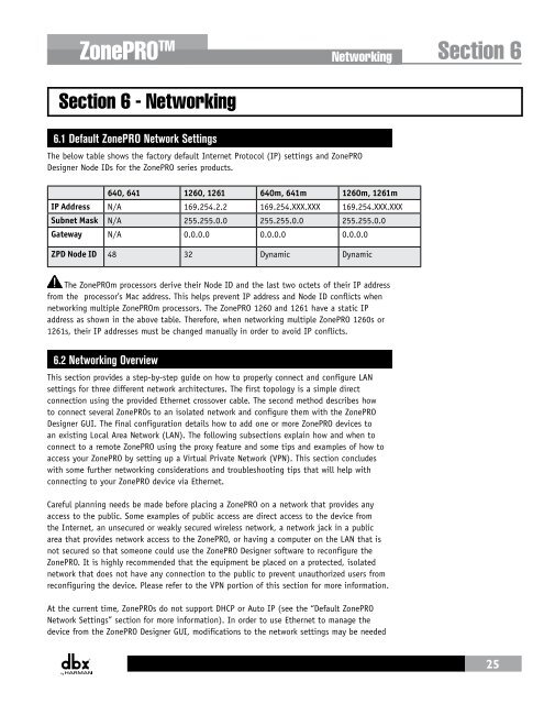
The below table shows the factory default Internet Protocol (IP) settings and <strong>ZonePRO</strong><br />
Designer Node IDs for the <strong>ZonePRO</strong> series products.<br />
640, 641 1260, 1261 640m, 641m 1260m, 1261m<br />
IP Address N/A 169.254.2.2 169.254.XXX.XXX 169.254.XXX.XXX<br />
Subnet Mask N/A 255.255.0.0 255.255.0.0 255.255.0.0<br />
Gateway N/A 0.0.0.0 0.0.0.0 0.0.0.0<br />
ZPD Node ID 48 32 Dynamic Dynamic<br />
The <strong>ZonePRO</strong>m processors derive their Node ID and the last two octets of their IP address<br />
from the processor’s Mac address. This helps prevent IP address and Node ID conflicts when<br />
networking multiple <strong>ZonePRO</strong>m processors. The <strong>ZonePRO</strong> 1260 and 1261 have a static IP<br />
address as shown in the above table. Therefore, when networking multiple <strong>ZonePRO</strong> 1260s or<br />
1261s, their IP addresses must be changed manually in order to avoid IP conflicts.<br />
6.2 Networking Overview<br />
This section provides a step-by-step guide on how to properly connect and configure LAN<br />
settings for three different network architectures. The first topology is a simple direct<br />
connection using the provided Ethernet crossover cable. The second method describes how<br />
to connect several <strong>ZonePRO</strong>s to an isolated network and configure them with the <strong>ZonePRO</strong><br />
Designer GUI. The final configuration details how to add one or more <strong>ZonePRO</strong> devices to<br />
an existing Local Area Network (LAN). The following subsections explain how and when to<br />
connect to a remote <strong>ZonePRO</strong> using the proxy feature and some tips and examples of how to<br />
access your <strong>ZonePRO</strong> by setting up a Virtual Private Network (VPN). This section concludes<br />
with some further networking considerations and troubleshooting tips that will help with<br />
connecting to your <strong>ZonePRO</strong> device via Ethernet.<br />
Careful planning needs be made before placing a <strong>ZonePRO</strong> on a network that provides any<br />
access to the public. Some examples of public access are direct access to the device from<br />
the Internet, an unsecured or weakly secured wireless network, a network jack in a public<br />
area that provides network access to the <strong>ZonePRO</strong>, or having a computer on the LAN that is<br />
not secured so that someone could use the <strong>ZonePRO</strong> Designer software to reconfigure the<br />
<strong>ZonePRO</strong>. It is highly recommended that the equipment be placed on a protected, isolated<br />
network that does not have any connection to the public to prevent unauthorized users from<br />
reconfiguring the device. Please refer to the VPN portion of this section for more information.<br />
At the current time, <strong>ZonePRO</strong>s do not support DHCP or Auto IP (see the “Default <strong>ZonePRO</strong><br />
Network Settings” section for more information). In order to use Ethernet to manage the<br />
device from the <strong>ZonePRO</strong> Designer GUI, modifications to the network settings may be needed<br />
25


