ZonePRO Install Guide-English - dbx
ZonePRO Install Guide-English - dbx ZonePRO Install Guide-English - dbx
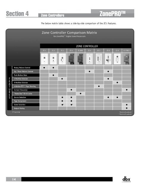
Section 4 Zone Controllers ZonePRO TM The below matrix table shows a side-by-side comparison of the ZC’s features. 14
ZonePRO TM Zone Controllers Section 4 4.2 ZC Wiring The installation of the Zone Controllers MUST be accomplished with the use of cable which is rated VW-1 or higher. Common NEC designations which meet this rating include: CMP, CMR, CMG, CM and CMX. The below diagram shows the internal color coding of a compatible straight-through, 568B standard Cat 5 cable. It also illustrates which DIP switch settings and controller ID numbers correspond with each wire inside the Cat 5 cable. Zone Controller Cable Specifications: Cat 5 Cable / 4-Twisted Pairs of 24 AWG Wire / 568B Standard RJ-45 (8-Position) White / Orange 1 1 2 Orange 2 3 White / Green 3 4 Blue 4 5 White / Blue 5 6 Green 6 7 White / Brown 7 8 Brown 8 RJ-45 (8-Position) Voltage Reference Controller 1/7 Controller 2/8 Controller 3/9 Controller 4/10 Controller 5/11 Controller 6/12 Ground ON 1 2 3 4 5 6 ON 1 2 3 4 5 6 ON 1 2 3 4 5 6 ON 1 2 3 4 5 6 ON 1 2 3 4 5 6 ON 1 2 3 4 5 6 The included Ethernet crossover cable cannot be used to connect ZCs to the ZonePRO! All Zone Controllers can be wired serially or in parallel. Whether using serial or parallel cabling, each Zone Controller must have a unique identification number chosen using the DIP switches on the side of the controller (see Diagram A), although there may be multiple Zone Controllers controlling a single zone or a single Zone Controller that controls multiple zones. This is explained in further detail in “Section 4.4 ZC DIP Switches & Programming”. Diagram A Two Zone Diagram Controllers B cannot be used to control the same parameter within the ZonePRO device! ID# 1 ID# 4 80-1342-A UL-6500 IEC60065 80-1342-A UL-6500 IEC60065 15 RJ45 CONNECT ONLY TO ZONE CONTROLLER INPU T . RJ45 CONNECT ONLY TO ZONE CONTROLLER INPU T . RS-232
- Page 1 and 2: ZonePROTM Digital Zone Processors 6
- Page 3: IMPORTANT SAFETY INSTRUCTIONS DECLA
- Page 7 and 8: ZonePRO TM Section 1 - Introduction
- Page 9 and 10: ZonePRO TM Introduction Section 1 1
- Page 11 and 12: ZonePRO TM ZonePRO Designer GUI Sec
- Page 13 and 14: ZonePRO TM ZonePRO Designer GUI Sec
- Page 15 and 16: ZonePRO TM Gettibg Started Section
- Page 17 and 18: ZonePRO TM Gettibg Started Section
- Page 19: ZonePRO TM Zone Controllers Section
- Page 23 and 24: ZonePRO TM Cable Specification: EIA
- Page 25 and 26: SELECT A B C D A B C D SELECT A B C
- Page 27 and 28: ZonePRO TM Zone Controllers Section
- Page 29 and 30: ZonePRO TM Link I/O Section 5 CAUTI
- Page 31 and 32: ZonePRO TM Section 6 - Networking N
- Page 33 and 34: ZonePRO TM Networking Section 6 6.4
- Page 35 and 36: ZonePRO TM Networking Section 6 a.
- Page 37 and 38: ZonePRO TM Networking Section 6 6.7
- Page 39 and 40: ZonePRO TM Networking Section 6 6.1
- Page 41 and 42: ZonePRO TM Application Guide Sectio
- Page 43 and 44: ZonePRO TM Application Guide Sectio
- Page 45 and 46: ZonePRO TM Application Guide Sectio
- Page 47 and 48: ZonePRO TM Appendix Section 8 8.2 Z
- Page 49 and 50: ZonePRO TM Appendix Section 8 8.4 Z
- Page 51 and 52: ZonePRO TM Appendix Section 8 The r
- Page 53 and 54: ZonePRO TM 640m/641m Appendix Secti
- Page 55 and 56: ZonePRO TM 1260m/1261m Appendix Sec
- Page 57 and 58: ZonePRO TM Appendix Section 8 8.8 W
- Page 59 and 60: ZonePRO TM Appendix Section 8 This
Section 4<br />
Zone Controllers<br />
<strong>ZonePRO</strong> TM<br />
The below matrix table shows a side-by-side comparison of the ZC’s features.<br />
14


