ZonePRO Install Guide-English - dbx
ZonePRO Install Guide-English - dbx
ZonePRO Install Guide-English - dbx

Create successful ePaper yourself
Turn your PDF publications into a flip-book with our unique Google optimized e-Paper software.
<strong>ZonePRO</strong>TM<br />
Digital Zone Processors<br />
640, 640m<br />
641, 641m<br />
1260, 1260m<br />
1261, 1261m<br />
<strong>Install</strong>ation <strong>Guide</strong>
IMPORTANT SAFETY INSTRUCTIONS<br />
WARNING FOR YOUR PROTECTION<br />
READ THE FOLLOWING:<br />
KEEP THESE INSTRUCTIONS<br />
HEED ALL WARNINGS<br />
The symbols shown above are internationally accepted symbols that warn of<br />
potential hazards with electrical products. The lightning flash with arrowpoint<br />
in an equilateral triangle means that there are dangerous voltages present<br />
within the unit. The exclamation point in an equilateral triangle indicates that<br />
it is necessary for the user to refer to the owner’s manual.<br />
These symbols warn that there are no user serviceable parts inside the unit.<br />
Do not open the unit. Do not attempt to service the unit yourself. Refer all<br />
servicing to qualified personnel. Opening the chassis for any reason will<br />
void the manufacturer’s warranty. Do not get the unit wet. If liquid is spilled<br />
on the unit, shut it off immediately and take it to a dealer for service.<br />
Disconnect the unit during storms to prevent damage.<br />
FOLLOW ALL INSTRUCTIONS<br />
the apparatus shall not be exposed to dripping or splashing liquid and no object filled with liquid, such as<br />
vases, shall be placed on the apparatus.<br />
CLEAN ONLY WITH A DRY CLOTH.<br />
DO NOT BLOCK ANY OF THE VENTILATION OPENINGS. INSTALL IN ACCORDANCE WITH THE<br />
MANUFACTURER’S INSTRUCTIONS.<br />
DO NOT INSTALL NEAR ANY HEAT SOURCES SUCH AS RADIATORS, HEAT REGISTERS, STOVES, OR OTHER<br />
APPARATUS (INCLUDING AMPLIFIERS) THAT PRODUCE HEAT.<br />
ONLY USE ATTACHMENTS/ACCESSORIES SPECIFIED BY THE MANUFACTURER.<br />
SAFETY INSTRUCTIONS<br />
Notice For Customers If Your Unit Is Equipped With A Power Cord.<br />
WARNING: THIS APPLIANCE SHALL BE CONNECTED TO A MAINS SOCKET OUTLET WITH A<br />
PROTECTIVE EARTHING CONNECTION.<br />
The cores in the mains lead are coloured in accordance with the following code:<br />
GREEN and YELLOW - Earth BLUE - Neutral BROWN - Live<br />
As colours of the cores in the mains lead of this appliance may not correspond with the<br />
coloured markings identifying the terminals in your plug, proceed as follows:<br />
• The core which is coloured green and yellow must be connected to the terminal in the plug<br />
marked with the letter E, or with the earth symbol, or coloured green, or green and yellow.<br />
• The core which is coloured blue must be connected to the terminal marked N or coloured<br />
black.<br />
• The core which is coloured brown must be connected to the terminal marked L or coloured<br />
red.<br />
UNPLUG THIS APPARATUS DURING LIGHTNING STORMS OR WHEN UNUSED FOR LONG PERIODS OF TIME.<br />
Do not defeat the safety purpose of the polarized or grounding-type plug. A polarized plug has two blades<br />
with one wider than the other. A grounding type plug has two blades and a third grounding prong. The<br />
wide blade or third prong are provided for your safety. If the provided plug does not fit your outlet, consult<br />
an electrician for replacement of the obsolete outlet.<br />
Protect the power cord from being walked on or pinched particularly at plugs, convenience receptacles, and<br />
the point where they exit from the apparatus.<br />
Use only with the cart stand, tripod bracket, or table specified by the manufacture, or sold with the<br />
apparatus. When a cart is used, use caution when moving the cart/apparatus combination to avoid injury<br />
from tip-over.<br />
This equipment may require the use of a different line cord, attachment plug, or both, depending<br />
on the available power source at installation. If the attachment plug needs to be changed,<br />
refer servicing to qualified service personnel who should refer to the table below. The green/<br />
yellow wire shall be connected directly to the units chassis.<br />
WIRE COLOR<br />
CONDUTOR<br />
Normal Alt<br />
L LIVE BROWN BLACK<br />
N NEUTRAL BLUE WHITE<br />
E EARTH GND<br />
GREEN/<br />
YEL<br />
GREEN<br />
WARNING: If the ground is defeated, certain fault conditions in the unit or in the system to<br />
which it is connected can result in full line voltage between chassis and earth ground. Severe<br />
injury or death can then result if the chassis and earth ground are touched simultaneously.<br />
Refer all servicing to to qualified service personnel. Servicing is required when the apparatus has been<br />
damaged in any way, such as power-supply cord or plug is damaged, liquid has been spilled or objects<br />
have fallen into the apparatus, the apparatus has been exposed to rain or moisture, does not operate<br />
normally, or has been dropped.<br />
POWER ON/OFF SWITCH: The Power switch used in this piece of equipment DOES NOT break the connection<br />
from the mains.<br />
If you want to dispose this product, do not mix it with general household waste. There is a<br />
separate collection system for used electronic products in accordance with legislation that<br />
requires proper treatment, recovery and recycling.<br />
Private household in the 25 member states of the EU, in Switzerland and Norway may return their used<br />
electronic products free of charge to designated collection facilities or to a retailer (if you purchase a similar<br />
new one).<br />
For Countries not mentioned above, please contact your local authorities for a correct method of disposal.<br />
By doing so you will ensure that your disposed product undergoes the necessary treatment, recovery and<br />
recycling and thus prevent potential negative effects on the environment and human health.<br />
MAINS DISCONNECT: The plug shall remain readily operable. For rack-mount or installation where plug is<br />
not accessible, an all-pole mains switch with a contact separation of at least 3 mm in each pole shall be<br />
incorporated into the electrical installation of the rack or building.<br />
If connected to 240V supply, a suitable CSA/UL certified power cord shall be used for this supply.
IMPORTANT SAFETY INSTRUCTIONS<br />
DECLARATION OF CONFORMITY<br />
DECLARATION OF CONFORMITY<br />
Manufacturer’s Name:<br />
Manufacturer’s Address:<br />
declares that the product:<br />
<strong>dbx</strong> Professional Products<br />
8760 S. Sandy Parkway<br />
sandy, Utah 84070, USA<br />
Manufacturer’s Name:<br />
Manufacturer’s Address:<br />
declares that the product:<br />
<strong>dbx</strong> Professional Products<br />
8760 S. Sandy Parkway<br />
sandy, Utah 84070, USA<br />
Product name: <strong>dbx</strong> 640, <strong>dbx</strong> 641<br />
<strong>dbx</strong> 640m, <strong>dbx</strong> 641m<br />
Note: Product name may be suffixed by the EU.<br />
Product option: None<br />
conforms to the following Product Specifications:<br />
Supplementary Information:<br />
Safety: IEC 60065 -01+Amd 1<br />
EMC: EN 55022:2006<br />
EN 55024:1998<br />
FCC Part 15<br />
The product herewith complies with the requirements of the:<br />
Low Voltage Directive 2006/95/EC<br />
EMC Directive 2004/108/EC.<br />
RoHS Directive 2002/95/EC<br />
WEEE Directive 2002/96/EC<br />
With regard to Directive 2005/32/EC and EC Regulation 1275/2008 of 17 December<br />
2008, this product is designed, produced, and classified as Professional Audio Equipment and<br />
thus is exempt from this Directive.<br />
Roger Johnsen<br />
Director, Engineering<br />
Signal Processing<br />
8760 S. Sandy Parkway<br />
Sandy, Utah 84070, USA<br />
Date: March 9, 2011<br />
European Contact: Your local <strong>dbx</strong> Sales and Service Office or<br />
Harman Signal Processing<br />
8760 South Sandy Parkway<br />
Sandy, Utah<br />
84070 USA<br />
Ph: (801) 566-8800<br />
Fax: (801) 568-7583<br />
Product name: <strong>dbx</strong> 1260, <strong>dbx</strong> 1261<br />
<strong>dbx</strong> 1260m, <strong>dbx</strong> 1261m<br />
Note: Product name may be suffixed by the EU.<br />
Product option: None<br />
conforms to the following Product Specifications:<br />
Supplementary Information:<br />
Safety: IEC 60065 -01+Amd 1<br />
EMC: EN 55022:2006<br />
EN 55024:1998<br />
FCC Part 15<br />
The product herewith complies with the requirements of the:<br />
Low Voltage Directive 2006/95/EC<br />
EMC Directive 2004/108/EC.<br />
RoHS Directive 2002/95/EC<br />
WEEE Directive 2002/96/EC<br />
With regard to Directive 2005/32/EC and EC Regulation 1275/2008 of 17 December<br />
2008, this product is designed, produced, and classified as Professional Audio Equipment and<br />
thus is exempt from this Directive.<br />
Roger Johnsen<br />
Director, Engineering<br />
Signal Processing<br />
8760 S. Sandy Parkway<br />
Sandy, Utah 84070, USA<br />
Date: March 9, 2011<br />
European Contact: Your local <strong>dbx</strong> Sales and Service Office or<br />
Harman Signal Processing<br />
8760 South Sandy Parkway<br />
Sandy, Utah<br />
84070 USA<br />
Ph: (801) 566-8800<br />
Fax: (801) 568-7583<br />
U.K. MAINS PLUG WARNING<br />
A molded mains plug that has been cut off from the cord is<br />
unsafe. Discard the mains plug at a suitable disposal facility.<br />
NEVER UNDER ANY CIRCUMSTANCES SHOULD<br />
YOU INSERT A DAMAGED OR CUT MAINS<br />
PLUG INTO A 13 AMP POWER SOCKET.<br />
Do not use the mains plug without the fuse cover in place.<br />
Replacement fuse covers can be obtained from your local<br />
retailer. Replacement fuses are 13 amps and MUST be<br />
ASTA approved to BS1362.<br />
ELECTROMAGNETIC COMPATIBILITY<br />
This device complies with part 15 of the FCC Rules and<br />
the Product Specifications noted on the Declaration of<br />
Conformity. Operation is subject to the following two<br />
conditions:<br />
• this device may not cause harmful interference, and<br />
• this device must accept any interference received,<br />
including interference that may cause undesired operation.<br />
Operation of this unit within significant<br />
electromagnetic fields should be avoided.<br />
• use only shielded interconnecting cables.
<strong>ZonePRO</strong> TM<br />
Table of Contents<br />
TOC<br />
Section 1 - Introduction........................................ 1<br />
1.1 <strong>ZonePRO</strong> Overview..........................................1<br />
1.2 Features........................................................1<br />
1.3 Included Items...............................................2<br />
1.4 <strong>ZonePRO</strong> Support Resources.............................2<br />
1.5 Service Contact Info........................................2<br />
1.6 Warranty........................................................3<br />
Section 2 - <strong>ZonePRO</strong> Designer GUI........................... 4<br />
2.1 <strong>ZonePRO</strong> Designer Overview..............................4<br />
2.2 GUI System Requirements................................4<br />
2.3 GUI <strong>Install</strong>ation.............................................5<br />
2.4 Quick Start – Connecting via RS-232.................5<br />
Section 3 - Getting Started..................................... 8<br />
3.1 Front Panel – 640/640m, 1260/1260m..............8<br />
3.2 Front Panel – 641/641m, 1261/1261m..............9<br />
3.3 Rear Panel.....................................................10<br />
Section 4 - Zone Controllers................................... 12<br />
4.1 ZC Descriptions...............................................12<br />
4.2 ZC Wiring.......................................................15<br />
4.3 ZC-4 Wiring....................................................18<br />
4.4 ZC DIP Switches & Programming.......................19<br />
Section 5 - Link I/O............................................... 22<br />
5.1 Link I/O Overview...........................................22<br />
5.2 Jumpers........................................................22<br />
5.3 Link I/O Wiring..............................................24<br />
Section 6 - Networking.......................................... 25<br />
6.1 Default <strong>ZonePRO</strong> Network Settings....................25<br />
6.2 Networking Overview.......................................25<br />
6.3 Overview of TCP/IP Basics...............................26<br />
6.4 Connecting via direct-connect Ethernet.............27<br />
6.5 Setup of a simple isolated Ethernet network.......28<br />
6.6 Adding the <strong>ZonePRO</strong> to an existing Local Area<br />
Network..............................................................30<br />
6.7 Proxy............................................................31<br />
6.8 Virtual Private Networks (VPN).........................32<br />
6.9 Network Considerations and Limitations.............32<br />
6.10 Network Troubleshooting................................33<br />
Section 7 - Application <strong>Guide</strong>................................. 34<br />
7.1 Restaurant Application....................................34<br />
7.2 Health Club Application...................................36<br />
7.3 Nightclub Application......................................38<br />
Section 8 - Appendix............................................. 40<br />
8.1 <strong>ZonePRO</strong> 640/641 Block Diagram......................40<br />
8.2 <strong>ZonePRO</strong> 640m/641m Block Diagram.................41<br />
8.3 <strong>ZonePRO</strong> 1260/1261 Block Diagram...................42<br />
8.4 <strong>ZonePRO</strong> 1260m/1261m Block Diagram..............43<br />
8.5 Firmware Updates...........................................44<br />
8.6 Factory Reset Procedures.................................44<br />
8.7 Technical Specifications...................................46<br />
8.8 Wiring Diagrams.............................................51<br />
8.9 Copyrights.....................................................52
<strong>ZonePRO</strong> TM<br />
Section 1 - Introduction<br />
1.1 <strong>ZonePRO</strong> Overview<br />
Introduction<br />
Section 1<br />
Congratulations on your purchase of the <strong>dbx</strong>® <strong>ZonePRO</strong>. The <strong>ZonePRO</strong> products are based<br />
on the same unparalleled design philosophy that made the DriveRack family famous. This<br />
philosophy, “To provide everything you need between the sources and the amplifiers”, creates<br />
a full-featured processor capable of almost any BGM or commercial audio application.<br />
The proceeding chart outlines the major differences between the <strong>dbx</strong> <strong>ZonePRO</strong> models.<br />
Total Inputs<br />
Total Outputs<br />
Balanced<br />
Mic/Line<br />
Inputs<br />
Unbalanced<br />
RCA Line<br />
Inputs<br />
2 Channel<br />
S/PDIF Input<br />
Front Panel<br />
Control<br />
Ethernet<br />
Port<br />
Mix Sources<br />
to Zones<br />
Ambient Noise<br />
Compensation<br />
1260m 12 6 6 4 Pair Q Q Q Q Q<br />
1260 12 6 2 8 Pair Q Q Q Q<br />
1261m 12 6 6 4 Pair Q Q Q Q<br />
1261 12 6 2 8 Pair Q Q Q<br />
640m 6 4 4 2 Pair Q Q Q Q<br />
640 6 4 2 4 Pair Q<br />
641m 6 4 4 2 Pair Q Q Q<br />
641 6 4 2 4 Pair<br />
1.2 Features<br />
• Advanced Feedback Suppression (AFS)<br />
• AutoWarmth®<br />
• Auto Gain Control (AGC)<br />
• Ambient Noise Compensation (640m, 641m, 1260m, & 1261m<br />
models only)<br />
• Bandpass/Crossover Filters<br />
• Compression<br />
• Delay<br />
• De-Essing<br />
• Limiting<br />
• Noise Gating<br />
• Notch Filtering<br />
• Parametric EQ<br />
• 2 Level Priority Ducker<br />
• Configuration, Scene, & Schedule Wizards<br />
• Compatible with <strong>dbx</strong> ZC Wall Panel Controllers<br />
• Independent Routing of Sources to Zones<br />
• Independent Mixing of Sources to Zones (640 & 641 do not<br />
support source mixing)<br />
• Independent Zone Volume & Source Selection Control<br />
• RS-232 & Ethernet Control (640 & 641 models do not support<br />
Ethernet control)<br />
• Security Lockout<br />
• Switchable Mic/Line Inputs<br />
• IEC, UI, and CSA Certified<br />
1
Section 1<br />
Introduction<br />
<strong>ZonePRO</strong> TM<br />
1.3 Included Items<br />
• <strong>ZonePRO</strong> Processor<br />
• Power Cable<br />
• RS-232 Null Modem Cable<br />
• Ethernet Crossover Cable (excluded from 640 & 641 models)<br />
• Software CD-ROM<br />
• <strong>Install</strong>ation <strong>Guide</strong><br />
1.4 <strong>ZonePRO</strong> Support Resources<br />
<strong>ZonePRO</strong> Designer Help - After installing the <strong>ZonePRO</strong> Designer GUI, see the included help for<br />
detailed information regarding <strong>ZonePRO</strong> programming and configuration.<br />
Training Videos - Training videos can be found under the “Training” section of our website<br />
located at www.<strong>dbx</strong>pro.com.<br />
FAQs/Solutions - Answers to frequently asked questions and solutions to common problems<br />
can be found under the “Support” section at www.<strong>dbx</strong>pro.com.<br />
<strong>dbx</strong> User Forum - The <strong>dbx</strong> User Forum can be found at www.<strong>dbx</strong>pro.com. Here you can search<br />
the forum for specific topics or ask other <strong>ZonePRO</strong> users questions regarding the <strong>ZonePRO</strong><br />
products.<br />
1.5 Service Contact Info<br />
If you require technical support, contact <strong>dbx</strong> Technical Support. Be prepared to accurately<br />
describe the problem. Know the serial number of your device – this is printed on a sticker<br />
attached to the chassis. If you have not already taken the time to register your product,<br />
please do so now. You may register online at www.<strong>dbx</strong>pro.com or fill out and send in the<br />
included warranty registration card.<br />
Before you return a product to the factory for service, we recommend you refer to the manual.<br />
Make sure you have correctly followed installation steps and operation procedures. For further<br />
technical assistance or service, please contact our Technical Support Department at (801)<br />
568-7660 or visit the support pages at www.<strong>dbx</strong>pro.com. If you need to return a product<br />
to the factory for service, you MUST first contact Technical Support or fill out the return<br />
authorization request form on the website to obtain a Return Authorization Number.<br />
No returned products will be accepted at the factory without a Return Authorization<br />
Number.<br />
Please refer to the Warranty information on the following page, which extends to the first<br />
end-user. After expiration of the warranty, a reasonable charge will be made for parts, labor,<br />
and packing if you choose to use the factory service facility. In all cases, you are responsible<br />
for transportation charges to the factory. <strong>dbx</strong> will pay return shipping if the device is still<br />
under warranty.<br />
Use the original packing material if it is available. Mark the package with the name of the<br />
shipper and with these words in red: DELICATE INSTRUMENT, FRAGILE! Insure the package<br />
properly. Ship prepaid, not collect. Do not ship parcel post.<br />
2
<strong>ZonePRO</strong> TM<br />
Introduction<br />
Section 1<br />
1.6 Warranty<br />
This warranty is valid only for the original purchaser and only in the United States.<br />
1. The warranty registration card that accompanies this product must be mailed within 30<br />
days after purchase date to validate this warranty. You can also register online at www.<br />
<strong>dbx</strong>pro.com. Proof-of-purchase is considered to be the responsibility of the consumer. A<br />
copy of the original purchase receipt must be provided for any warranty service.<br />
2. <strong>dbx</strong> warrants this product, when bought and used solely within the U.S., to be free from<br />
defects in materials and workmanship under normal use and service.<br />
3. <strong>dbx</strong> liability under this warranty is limited to repairing or, at our discretion, replacing<br />
defective materials that show evidence of defect, provided the product is returned to <strong>dbx</strong><br />
WITH RETURN AUTHORIZATION from the factory, where all parts and labor will be covered<br />
up to a period of two years. A Return Authorization number must first be obtained from<br />
<strong>dbx</strong>. The company shall not be liable for any consequential damage as a result of the<br />
product’s use in any circuit or assembly.<br />
4. <strong>dbx</strong> reserves the right to make changes in design or make additions to or improvements<br />
upon this product without incurring any obligation to install the same additions or<br />
improvements on products previously manufactured.<br />
5. The foregoing is in lieu of all other warranties, expressed or implied, and <strong>dbx</strong> neither<br />
assumes nor authorizes any person to assume on its behalf any obligation or liability in<br />
connection with the sale of this product. In no event shall <strong>dbx</strong> or its dealers be liable for<br />
special or consequential damages or from any delay in the performance of this warranty<br />
due to causes beyond their control.<br />
3
Section 2<br />
<strong>ZonePRO</strong> Designer GUI<br />
<strong>ZonePRO</strong> TM<br />
Section 2 - <strong>ZonePRO</strong> Designer GUI<br />
2.1 <strong>ZonePRO</strong> Designer Overview<br />
The <strong>ZonePRO</strong> Designer Graphic User Interface (GUI) is the included software application which<br />
is used for programming the <strong>ZonePRO</strong> products. The GUI provides network tools for configuring<br />
your control network as well as multiple “Wizard” functions for configuring the system routing<br />
and in-wall <strong>dbx</strong> Zone Controllers. The GUI also allows you to adjust DSP effect parameters and<br />
even create automatic system changes (referred to as “Scene Changes”).<br />
Understanding the <strong>ZonePRO</strong> Designer GUI is essential for getting the most out of the <strong>ZonePRO</strong><br />
processors. After installing the <strong>ZonePRO</strong> Designer GUI, please see the software application’s<br />
help section for detailed information and assistance with the <strong>ZonePRO</strong> Designer GUI. Training<br />
videos are also available at www.<strong>dbx</strong>pro.com.<br />
2.2 GUI System Requirements<br />
1 GHz or faster processor<br />
Windows 2000/XP/Vista (32 bit)/7 (32 bit)<br />
256 MB RAM (512 MB Recommended)<br />
Recommended screen resolution: 1024 x 768 pixels or higher<br />
4
<strong>ZonePRO</strong> TM<br />
<strong>ZonePRO</strong> Designer GUI Section 2<br />
2.3 GUI <strong>Install</strong>ation<br />
1. <strong>Install</strong> the <strong>ZonePRO</strong> GUI software onto your computer from either the <strong>dbx</strong> website at<br />
www.<strong>dbx</strong>pro.com or from the included CD ROM.<br />
We highly recommend disabling virus protection software during the installation<br />
of <strong>ZonePRO</strong> Designer.<br />
2. The application will proceed to prompt you for the installation location.<br />
3. Once the software installation has been completed, it is recommended that you restart<br />
your computer.<br />
2.4 Quick Start – Connecting via RS-232<br />
In order to program the <strong>ZonePRO</strong> processors, the <strong>ZonePRO</strong> Designer GUI must be in<br />
communication with the <strong>ZonePRO</strong> device (this is referred to as “Online”). Once communication<br />
is established, the <strong>ZonePRO</strong> processor can be programmed in real-time, or if a program has<br />
already been created, it can be loaded into the device.<br />
If your computer does not have a built in RS-232 port you must use a compatible RS-232<br />
peripheral, such as an RS-232 PCI card, RS-232 PCMCIA card, or USB to Serial adapter. Please<br />
visit the FAQs section of the <strong>dbx</strong> website for the latest information on compatible RS-232<br />
peripherals.<br />
Most <strong>ZonePRO</strong> models also allow you to communicate via Ethernet, the exception being the<br />
640 and 641 models, which do not have an Ethernet control port. If you are connecting via<br />
Ethernet and require assistance, please see “Section 6 - Networking”.<br />
It is highly recommended that <strong>ZonePRO</strong> installers do have the means to communicate<br />
with the <strong>ZonePRO</strong> processors via RS-232. If a firmware update is ever required, the firmware<br />
update must be applied using the RS-232 connection!<br />
Going Online via RS-232<br />
1. Connect your computer to the <strong>ZonePRO</strong>’s front or rear RS-232<br />
port using the provided <strong>dbx</strong> female to female null modem<br />
cable.<br />
PC<br />
<strong>ZonePRO</strong><br />
Computer<br />
A straight-through RS-232 cable will not work! If using<br />
a USB to Serial adapter, the <strong>dbx</strong> null modem cable must be<br />
plugged in between the adapter and the <strong>ZonePRO</strong>. See section<br />
“8.8 Wiring Diagrams” for a wiring diagram of the RS-232 null<br />
modem cable.<br />
<strong>dbx</strong> RS-232 Cable<br />
2. Launch <strong>ZonePRO</strong> Designer.<br />
5
Section 2<br />
<strong>ZonePRO</strong> Designer GUI<br />
<strong>ZonePRO</strong> TM<br />
3. Wait approximately 10 seconds after the main <strong>ZonePRO</strong><br />
Designer window has appeared. If a <strong>ZonePRO</strong> icon appears in<br />
the upper left hand corner of the window, you are online with<br />
the processor and ready to begin programming. Simply double<br />
left click on the <strong>ZonePRO</strong> icon to open the Program Screen and<br />
begin programming. If the icon does not automatically appear,<br />
proceed with these instructions.<br />
4. Go into Window’s Device Manager > Ports. Take note of your<br />
COM port’s assigned COM number (shown in parenthesis). If<br />
you do not see your COM port here, you may need to reinstall<br />
the drivers for your COM port peripheral.<br />
5. Double left click on the connected COM port listed in the<br />
previous step. Click the Port Settings tab and set your COM<br />
port settings as shown to the right then click the OK button.<br />
6. Go back into <strong>ZonePRO</strong> Designer and go to Network ><br />
Properties.<br />
6
<strong>ZonePRO</strong> TM<br />
<strong>ZonePRO</strong> Designer GUI Section 2<br />
7. Ensure that the “Automatically go online when the application<br />
starts” option is checked and the “Use serial ports” option is<br />
checked. In the COM Ports combo box, uncheck any unused<br />
COM ports and check only the COM port number which you<br />
noted in step 4. Click the Next button twice.<br />
8. Your connected <strong>ZonePRO</strong> device should appear on the second<br />
row of the table and have a Status of “Resolved”. If it does<br />
not, ensure that the RS-232 cable is securely connected and<br />
that you are using the correct RS-232 cable and a compatible<br />
RS-232 peripheral. If the <strong>ZonePRO</strong> device appears in the table<br />
proceed by clicking the Finish button.<br />
9. Select Network > Go Online. The icon of the <strong>ZonePRO</strong><br />
should now appear in the upper left corner of the window.<br />
You are now online with the processor and ready to begin<br />
programming. Simply double left click on the <strong>ZonePRO</strong> icon to<br />
open the Program Screen and begin programming.<br />
7
Section 3<br />
Getting Started<br />
<strong>ZonePRO</strong> TM<br />
Section 3 - Getting Started<br />
3.1 Front Panel – 640/640m, 1260/1260m<br />
640 Front Panel<br />
1<br />
2<br />
3 4<br />
7<br />
5<br />
6<br />
7<br />
5<br />
6<br />
7<br />
5<br />
6<br />
7<br />
5<br />
6<br />
1<br />
2<br />
640m Front Panel<br />
3 4<br />
7<br />
5<br />
6<br />
7<br />
5<br />
6<br />
7<br />
5<br />
6<br />
7<br />
5<br />
6<br />
1<br />
2<br />
1260 Front Panel<br />
3 4<br />
SELECT<br />
SELECT<br />
7<br />
5<br />
SELECT<br />
6<br />
5<br />
7<br />
SELECT<br />
6<br />
7<br />
5<br />
SELECT<br />
6<br />
7<br />
5<br />
SELECT<br />
6<br />
7<br />
5<br />
SELECT<br />
6<br />
7<br />
5<br />
SELECT<br />
6<br />
Z onePRO1260<br />
Digital Zone Processor<br />
1<br />
2<br />
1260m Front Panel<br />
3 4<br />
SELECT<br />
SELECT<br />
5<br />
7<br />
SELECT 6<br />
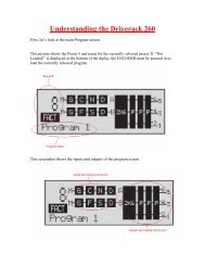
1. Front Panel LCD<br />
Displays information relating to parameters such as source selection, page steering,<br />
zone volumes, and mutes.<br />
2. Parameter Select Buttons 1-3<br />
Allows selection of parameters on display.<br />
3. Data Wheel<br />
Used to edit parameter values.<br />
4. Page Buttons<br />
Allows paging microphone path selection for page steering of the ML1 and ML2 inputs.<br />
5. Output Select Button<br />
Allows selection of outputs for controlling source selection, zone volume control, and<br />
zone muting.<br />
6. Output Meter<br />
Six-segment output level meter representing -30dBu to +20dBu.<br />
7. Threshold Indicator<br />
Indicates that the threshold level has been exceeded within the output dynamics<br />
processor and that dynamics processing may be occurring.<br />
5<br />
7<br />
SELECT<br />
6<br />
5<br />
7<br />
SELECT<br />
6<br />
5<br />
7<br />
SELECT<br />
6<br />
5<br />
7<br />
SELECT<br />
6<br />
5<br />
7<br />
SELECT<br />
6<br />
8
<strong>ZonePRO</strong> TM<br />
Gettibg Started Section 3<br />
and dynamics processing may be occurring.<br />
3.2 Front Panel – 641/641m, 1261/1261m<br />
641 Front Panel<br />
1 3<br />
641m Front Panel<br />
1 2 3<br />
1261 Front Panel<br />
NETWORK<br />
POWER<br />
1 TRAFFIC 2 3<br />
<strong>ZonePRO</strong>1261<br />
Digital Zone Processor<br />
1261m Front Panel<br />
1 2 3<br />
1. Front PC Port (RS-232)<br />
Connect this serial port to the PC for configuration, control, and monitoring. It can<br />
also be used for communication with a third party control system. The baud rate of this<br />
port is 57600.<br />
Front and rear PC ports should not be used at the same time!<br />
2. Network Traffic LED (641m, 1261, and 1261m only)<br />
This LED (when lit), indicates that network traffic is present.<br />
3. Power LED<br />
This LED (when lit) indicates that the <strong>ZonePRO</strong> device is currently powered on.<br />
9
Section 3<br />
Getting Started<br />
3.3 Rear Panel<br />
640/641 Rear Panel<br />
<strong>ZonePRO</strong> TM<br />
1<br />
3<br />
5<br />
6<br />
7<br />
8<br />
11 10 10<br />
12<br />
9 9<br />
11<br />
640m/641m Rear Panel<br />
1<br />
3<br />
RS-232<br />
ETHERNET<br />
4<br />
ZC INPUT<br />
5<br />
ZC INPUT<br />
OUTPUTS<br />
CH 4 CH 3<br />
CH 2<br />
CH 1<br />
LINK INPUT<br />
LINK OUTPUT<br />
S2<br />
SOURCE<br />
6 7<br />
8<br />
L<br />
R<br />
S1<br />
9<br />
11<br />
MIC GAIN<br />
MIC<br />
LINE<br />
MIC/LINE<br />
MIC/LINE<br />
(R) CLIP 10 CLIP (R)<br />
(R) CLIP<br />
CLIP (R)<br />
(G) SIGNAL SIGNAL (G) 9 10<br />
(G) SIGNAL SIGNAL (G) 9<br />
MIC GAIN MIC GAIN<br />
MIC GAIN<br />
ML 4 ML 3<br />
ML 2 ML 1<br />
12<br />
MIC<br />
MIC<br />
11<br />
12<br />
11<br />
MIC<br />
LINE<br />
LINE<br />
LINE<br />
1260/1261 Rear Panel<br />
1<br />
S/PDIF<br />
INPUT<br />
3<br />
2<br />
PC<br />
10/100 BaseT<br />
4<br />
ZC INPUT<br />
5<br />
ZC INPUT<br />
OUTPUTS<br />
LINK INPUT<br />
SOURCE MIC/LINE<br />
(R) CLIP<br />
10<br />
CLIP (R)<br />
(G) SIGNAL SIGNAL (G)<br />
6<br />
L L L<br />
L L L<br />
L<br />
MIC GAIN<br />
CH 6 CH 5 CH 4<br />
CH 3 CH 2 CH 1 ML 2 ML 1<br />
LINE MIC<br />
7<br />
LINK OUTPUT<br />
8<br />
R<br />
R R R<br />
R R R<br />
S8 S7 S6 S4 S2<br />
S5 S3 S1<br />
9 9<br />
12<br />
MIC GAIN<br />
LINE<br />
MIC<br />
11 11<br />
1260m/1261m Rear Panel<br />
1<br />
3<br />
2<br />
RS-232<br />
4<br />
5<br />
6<br />
7<br />
8<br />
9<br />
11<br />
10<br />
12<br />
9<br />
11<br />
10<br />
12<br />
9<br />
11<br />
10<br />
12<br />
9<br />
11<br />
1. Power Connector<br />
Connect the included AC power cable to this IEC connector.<br />
2. S/PDIF Input (1260, 1261, 1260m, and 1261m models only)<br />
Digital audio input for up to two channels of digital audio.<br />
3. Rear PC Port (RS-232)<br />
Connect this serial port to the PC for configuration, control, and monitoring. It can<br />
also be used for communication with a third party control system. The baud rate of this<br />
port is 57600.<br />
Front and rear PC ports should not be used at the same time!<br />
4. Ethernet Port (all models except 640 and 641)<br />
Connect this Ethernet port to the PC for configuration, control, and monitoring. It can<br />
also be used for communication with a third party control system.<br />
10
<strong>ZonePRO</strong> TM<br />
Gettibg Started Section 3<br />
5. ZC Input Ports<br />
Allows connection of up to 12 ZC controllers (six per port) for control of volume, source<br />
selection, page steering, and scene changes. The top ZC Input port is for IDs 1-6 and<br />
the bottom ZC Input port is for IDs 7-12.<br />
6. Analog Outputs<br />
Balanced audio output connections. Connect these outputs to your amplifier input<br />
channels.<br />
7. Link Input/Output Ports<br />
Allows duplication of up to six input channels (ML1, ML2, S1, S2, S3, S4) to another<br />
<strong>ZonePRO</strong> device in applications where additional output zones are required.<br />
All models – with the exception of the 640m and 641m – allow duplication of<br />
up to six channels: ML1, ML2, S1, S2, S3, S4. The 640m and 641m models allow<br />
duplication of up to four channels: ML1, ML2, S1, S2.<br />
8. RCA Source Inputs<br />
Mono-summed pairs of unbalanced RCA audio inputs.<br />
Each pair of unbalanced RCA inputs are<br />
internally mono summed. This is beneficial when<br />
your application requires mono zones. However, when<br />
stereo zones are required and stereo imaging is to be<br />
maintained, each stereo source must occupy two pairs<br />
of inputs (omitting one jack per pair).<br />
Stereo RCA<br />
Connection Example<br />
L<br />
R<br />
S2<br />
L<br />
R<br />
S1<br />
9. Mic Gain Control<br />
Allows microphone gain control when the mic/line inputs are set to mic level.<br />
10. Signal/Clip LED<br />
This LED indicates when signal is present (green) or the input is clipping (red).<br />
11. Mic/Line Switch<br />
Allows configuration for microphone or line level sources.<br />
12. Mic/Line Input Connectors<br />
These balanced inputs provide Euroblock connectors for mic or line level sources.<br />
These Euroblock inputs provide 15 Volts of phantom power when the mic/line<br />
switch is set to mic level.<br />
Right<br />
Left<br />
11
MUTE<br />
Section 4<br />
Zone Controllers<br />
<strong>ZonePRO</strong> TM<br />
Section 4 - Zone Controllers<br />
4.1 ZC Descriptions<br />
The <strong>dbx</strong> Zone Controllers (ZCs) provide a user friendly solution for controlling different<br />
functions of the <strong>ZonePRO</strong> processors. The following section provides a description of each of<br />
these ZC models.<br />
VOLUME<br />
4<br />
5<br />
3<br />
2<br />
1<br />
0<br />
6<br />
7<br />
8<br />
9<br />
10 ZC-1<br />
– The ZC-1 is a programmable zone controller that allows input or output volume<br />
level control from a wall panel.<br />
VOLUME<br />
4<br />
5<br />
6<br />
3<br />
7<br />
2<br />
8<br />
1<br />
9<br />
0 10<br />
ZC-2 – The ZC-2 is a programmable zone controller that allows output volume level and<br />
mute control from a wall panel.<br />
SELECT<br />
A<br />
B<br />
C<br />
D<br />
A<br />
B<br />
C<br />
D<br />
ZC-3 – The ZC-3 is a programmable zone controller that allows control of source selection,<br />
page steering, or scene selection via a four position rotary control.<br />
The ZC-3 must be assigned as ID#1 and connected to the <strong>ZonePRO</strong>’s top ZC Input<br />
connector for scene selection control.<br />
+V 1 2 3 4 OUT IN<br />
ZC-4 – The ZC-4 is a programmable zone controller that allows control of source selection,<br />
page steering, or scene selection via contact closure.<br />
The ZC-4 must be assigned as ID#1 and connected to the <strong>ZonePRO</strong>’s top ZC Input<br />
connector for scene selection control.<br />
1 2 3<br />
ZC-BOB – The ZC-BOB allows parallel (also known as “home run”) cabling of the Zone<br />
Controllers.<br />
4 5 6<br />
Each <strong>ZonePRO</strong> device can accommodate up to two ZC-BOBs. Daisy chaining ZCs off<br />
the ZC-BOB is not supported!<br />
12
<strong>ZonePRO</strong> TM<br />
Zone Controllers<br />
Section 4<br />
VOLUME<br />
ZC-6 – The ZC-6 is a push-button up/down input or output volume controller.<br />
ZC-6<br />
A<br />
B<br />
C<br />
D<br />
ZC-7 – The ZC-7 is a programmable zone controller that allows control of page steering via<br />
four momentary push buttons. The ZC-7 has 5 states: button A pressed, button B pressed,<br />
button C pressed, button D pressed, and “no button pressed” being the 5th state.<br />
ZC-7<br />
VOLUME<br />
SELECT<br />
A<br />
B A<br />
C<br />
B<br />
D<br />
C<br />
D<br />
ZC-8 – The ZC-8 is used for combination up/down output volume control and four position<br />
source selection control.<br />
ZC-8<br />
C D E F<br />
B<br />
G<br />
A<br />
H<br />
A<br />
B<br />
C<br />
D<br />
E<br />
F<br />
ZC-9 – The ZC-9 provides source selection control via an eight position rotary selector.<br />
G<br />
H<br />
ZC-9<br />
INPUTS<br />
RELAY/<br />
CONTROL<br />
SWITCH VOLTAGE<br />
CLOSURE 5-24 VDC<br />
RJ45 - CONNECT ONLY TO<br />
ZONE CONTROLLER INPUT<br />
OUT<br />
IN<br />
ZC-FIRE – The ZC-FIRE is the interface to generic fire alarm relays. When the fire alarm<br />
activates, the general purpose relay can typically be programmed to close if normally<br />
open or vices-versa. The ZC-FIRE interface unit monitors the state of the relay (n.o. or<br />
n.c.) and upon the state of change, notifies the <strong>ZonePRO</strong> to mute the outputs or load a<br />
pre-programmed “Fire” scene. Control Voltage (5-24 VDC) can also be used for triggering the<br />
ZC-FIRE.<br />
The ZC-FIRE must be assigned as ID#2 and connected to the <strong>ZonePRO</strong>’s top ZC<br />
Input connector for fire control.<br />
13
Section 4<br />
Zone Controllers<br />
<strong>ZonePRO</strong> TM<br />
The below matrix table shows a side-by-side comparison of the ZC’s features.<br />
14
<strong>ZonePRO</strong> TM<br />
Zone Controllers<br />
Section 4<br />
4.2 ZC Wiring<br />
The installation of the Zone Controllers MUST be accomplished with the use of cable which is<br />
rated VW-1 or higher. Common NEC designations which meet this rating include: CMP, CMR,<br />
CMG, CM and CMX.<br />
The below diagram shows the internal color coding of a compatible straight-through, 568B<br />
standard Cat 5 cable. It also illustrates which DIP switch settings and controller ID numbers<br />
correspond with each wire inside the Cat 5 cable.<br />
Zone Controller Cable Specifications:<br />
Cat 5 Cable / 4-Twisted Pairs of 24 AWG Wire / 568B Standard<br />
RJ-45<br />
(8-Position)<br />
White / Orange<br />
1 1<br />
2<br />
Orange<br />
2<br />
3<br />
White / Green<br />
3<br />
4<br />
Blue<br />
4<br />
5<br />
White / Blue<br />
5<br />
6<br />
Green<br />
6<br />
7<br />
White / Brown<br />
7<br />
8<br />
Brown<br />
8<br />
RJ-45<br />
(8-Position)<br />
Voltage Reference<br />
Controller 1/7<br />
Controller 2/8<br />
Controller 3/9<br />
Controller 4/10<br />
Controller 5/11<br />
Controller 6/12<br />
Ground<br />
ON<br />
1 2 3 4 5 6<br />
ON<br />
1 2 3 4 5 6<br />
ON<br />
1 2 3 4 5 6<br />
ON<br />
1 2 3 4 5 6<br />
ON<br />
1 2 3 4 5 6<br />
ON<br />
1 2 3 4 5 6<br />
The included Ethernet crossover cable cannot be used to connect ZCs to the <strong>ZonePRO</strong>!<br />
All Zone Controllers can be wired serially or in parallel. Whether using serial or parallel<br />
cabling, each Zone Controller must have a unique identification number chosen using the DIP<br />
switches on the side of the controller (see Diagram A), although there may be multiple Zone<br />
Controllers controlling a single zone or a single Zone Controller that controls multiple zones.<br />
This is explained in further detail in “Section 4.4 ZC DIP Switches & Programming”.<br />
Diagram A<br />
Two Zone Diagram Controllers B cannot be used to control the same parameter within the <strong>ZonePRO</strong><br />
device!<br />
ID# 1 ID# 4<br />
80-1342-A<br />
UL-6500<br />
IEC60065<br />
80-1342-A<br />
UL-6500<br />
IEC60065<br />
15<br />
RJ45<br />
CONNECT ONLY TO<br />
ZONE CONTROLLER<br />
INPU T .<br />
RJ45<br />
CONNECT ONLY TO<br />
ZONE CONTROLLER<br />
INPU T .<br />
RS-232
Diagram A<br />
Section 4<br />
Zone Controllers<br />
<strong>ZonePRO</strong> TM<br />
Diagram A<br />
Wiring In Series<br />
To wire the Zone Controllers in series, daisy chain each ZC using the ports on each (see<br />
Diagram B) then connect one of the ZCs to the appropriate ZC Input Port on the <strong>ZonePRO</strong><br />
device. It is not important which ZC port you use on each ZC or which ZC in the chain is<br />
connected to the <strong>ZonePRO</strong> device.<br />
Diagram B<br />
ID# 1 ID# 4<br />
80-1342-A<br />
UL-6500<br />
80-1342-A<br />
UL-6500<br />
IEC60065<br />
IEC60065<br />
RJ45<br />
CONNECT ONLY TO<br />
ZONE CONTROLLER<br />
INPU T .<br />
RJ45<br />
CONNECT ONLY TO<br />
ZONE CONTROLLER<br />
INPU T .<br />
RS-232<br />
Diagram B<br />
ID# 1 ID# 4<br />
80-1342-A<br />
UL-6500<br />
80-1342-A<br />
UL-6500<br />
RS-232<br />
Wiring In Parallel<br />
To wire Diagram the Zone C Controllers in parallel, a ZC-BOB must be used. To wire in parallel, each<br />
Zone Controller must be wired into one of the ZC-BOB’s numbered ports. The ZC BOB’s<br />
Output port is then connected to one of the <strong>ZonePRO</strong>’s ZC Input ports (see Diagram C). For<br />
troubleshooting purposes, it is recommended to match the numbered ports on the ZC-BOB<br />
with the corresponding DIP switch assignments on each ZC (for example, ID#6 or ID#12 would<br />
RS-232<br />
be connected to the #6 port on the ZC-BOB).<br />
RJ45<br />
CONNECT ONLY TO<br />
ZONE CONTROLLER<br />
INPU T .<br />
IEC60065<br />
RJ45<br />
CONNECT ONLY TO<br />
ZONE CONTROLLER<br />
INPU T .<br />
IEC60065<br />
Diagram C<br />
RS-232<br />
Each <strong>ZonePRO</strong> device can accommodate up to two ZC-BOBs. Daisy chaining ZCs off the<br />
ZC-BOB is not supported!<br />
16
<strong>ZonePRO</strong> TM<br />
Cable Specification: EIA/TIA 568A Standard (pin to pin) 24 AWG wire<br />
RJ-45<br />
(8-Position)<br />
RJ-45<br />
(8-Position)<br />
1<br />
1 -VREF<br />
Maximum Cable Lengths<br />
2 Green<br />
2 -Dip 1<br />
Depending upon how many controllers you are connecting to the <strong>ZonePRO</strong> and whether you<br />
3 White/Orange 3 -Dip 2<br />
are wiring the ZCs in parallel or serially, there are certain cable length restrictions.<br />
4<br />
5<br />
White/Green<br />
Blue<br />
White/Blue<br />
Orange<br />
Diagram A shows the maximum 6 cable length for 3 ZCs wired 6 -Dip in serial. 5 Diagram B shows the<br />
maximum cable length for 67<br />
White/Brown<br />
ZCs wired in serial. Diagram C 7 shows -Dip 6the maximum length for<br />
8 Brown<br />
8 -GND<br />
each cable run when connecting the ZCs in parallel using a ZC-BOB and the maximum cable<br />
length of the cable between the ZC-BOB and <strong>ZonePRO</strong> device.<br />
4<br />
5<br />
-Dip 3<br />
-Dip 4<br />
Zone Controllers<br />
Section 4<br />
Diagram A<br />
RS-232<br />
Diagram B<br />
RS-232<br />
Diagram C<br />
RS-232<br />
Number of ZCs Daisy Chained in Series Maximum Total Cable Length<br />
1 ZC 1000 ft.<br />
2 ZCs 800 ft.<br />
3 ZCs 600 ft.<br />
4 ZCs 500 ft.<br />
5 ZCs 400 ft.<br />
6 ZCs 300 ft.<br />
17
Section 4<br />
Zone Controllers<br />
<strong>ZonePRO</strong> TM<br />
4.3 ZC-4 Wiring<br />
The below diagrams show how to configure and wire a ZC-4 for contact closure control using<br />
relays or SPDT (single pole double throw) type switches.<br />
All pins on the ZC-4 must be connected! Any pins not directly connected to a switch or<br />
relay should be connected to the +V pin.<br />
controller.<br />
<strong>ZonePRO</strong> devices.<br />
18
SELECT<br />
A<br />
B<br />
C<br />
D<br />
A<br />
B<br />
C<br />
D<br />
SELECT<br />
A<br />
B<br />
C<br />
D<br />
A<br />
B<br />
C<br />
D<br />
<strong>ZonePRO</strong> TM<br />
Zone Controllers<br />
Section 4<br />
4.4 ZC DIP Switches & Programming<br />
When configuring the ZCs, there are two steps which need to be completed before the ZCs will<br />
function:<br />
• Step 1: Assign the ZC IDs and perform the ZC Configuration programming<br />
• Step 2: Associate the ZCs<br />
The programming of the ZCs is performed using the<br />
Configuration Wizard in <strong>ZonePRO</strong> Designer.<br />
Step 1: Assign the ZC IDs and perform the ZC Configuration programming<br />
The ID# assignments on each Zone Controller, set using the DIP switches on the side of each,<br />
must correspond with the appropriate ZC Input port on the back of the <strong>ZonePRO</strong> device and<br />
with the program loaded into the <strong>ZonePRO</strong>.<br />
Top ZC Input Port (1-6)<br />
The top ZC Input port on the back of the <strong>ZonePRO</strong><br />
device corresponds with ID#s 1-6. Therefore, to<br />
select ID#2 for example, simply flip the 2 DIP<br />
switch into the on position and connect the ZC to<br />
the top ZC Input port on the <strong>ZonePRO</strong>. You must<br />
then program this ZC, on the corresponding ZC<br />
Panel Configuration page in <strong>ZonePRO</strong> Designer’s<br />
Configuration Wizard, as ZC Input 2 (ID#2).<br />
<strong>ZonePRO</strong> Designer<br />
Software Programming<br />
ID#2<br />
DIP<br />
Switches<br />
ZCs<br />
ZC-3<br />
ID’s 1-6<br />
(Top ZC Input Port)<br />
ZC INPUT<br />
ZC INPUT<br />
Bottom ZC Input Port (7-12)<br />
The bottom ZC Input port on the back of the<br />
<strong>ZonePRO</strong> device corresponds with ID#s 7-12. The<br />
physical DIP switch settings simply start over or<br />
repeat when connecting to the bottom ZC Input<br />
port on the <strong>ZonePRO</strong>. For example, to create ID#s<br />
7-12, add 6 to the ID# selected on the ZC’s DIP<br />
switch. For example, to get an ID# of 10, connect<br />
to the bottom ZC Input port and set the ID# to<br />
4 (4+6=10). You must then program this ZC, on<br />
the corresponding ZC Panel Configuration page in<br />
<strong>ZonePRO</strong> Designer’s Configuration Wizard, as ZC<br />
Input 10 (ID#10).<br />
ZC INPUT<br />
ZC INPUT<br />
ID’s 7-12<br />
(Bottom ZC Input Port)<br />
ZCs<br />
ZC-3<br />
DIP<br />
Switches<br />
ID#10<br />
<strong>ZonePRO</strong> Designer<br />
Software Programming<br />
19
VOLUME<br />
4<br />
5<br />
6<br />
3<br />
7<br />
2<br />
8<br />
1<br />
9<br />
0 10<br />
A<br />
B<br />
C<br />
D<br />
3<br />
2<br />
1<br />
A<br />
B<br />
C<br />
D<br />
3<br />
2<br />
1<br />
A<br />
B<br />
C<br />
D<br />
4<br />
0<br />
4<br />
0<br />
SELECT<br />
A<br />
VOLUME<br />
5<br />
SELECT<br />
A<br />
6<br />
VOLUME<br />
5<br />
SELECT<br />
A<br />
B<br />
7<br />
8<br />
9<br />
10<br />
B<br />
6<br />
7<br />
8<br />
9<br />
10<br />
B<br />
C<br />
D<br />
C<br />
D<br />
C<br />
D<br />
3<br />
2<br />
1<br />
A<br />
B<br />
C<br />
D<br />
3<br />
2<br />
1<br />
A<br />
B<br />
C<br />
D<br />
3<br />
2<br />
1<br />
A<br />
B<br />
C<br />
D<br />
4<br />
0<br />
4<br />
0<br />
4<br />
0<br />
VOLUME<br />
5<br />
SELECT<br />
A<br />
6<br />
VOLUME<br />
5<br />
SELECT<br />
A<br />
7<br />
8<br />
9<br />
10<br />
6<br />
VOLUME<br />
5<br />
SELECT<br />
A<br />
B<br />
7<br />
8<br />
9<br />
10<br />
B<br />
6<br />
7<br />
8<br />
9<br />
10<br />
B<br />
C<br />
D<br />
C<br />
D<br />
C<br />
D<br />
Section 4<br />
Zone Controllers<br />
<strong>ZonePRO</strong> TM<br />
ID’s 1-6<br />
(Top ZC Input Port)<br />
The below diagram shows an example of the DIP switch ID assignments, ZC Input port<br />
connections, and ZC Panel Configuration programming for 12 Zone Controllers.<br />
ID’s 7-12<br />
(Bottom ZC Input Port)<br />
<strong>ZonePRO</strong> Designer<br />
Software Programming<br />
ID#1<br />
DIP<br />
Switches<br />
ZCs<br />
ZC-1<br />
ZC INPUT<br />
ZCs<br />
ZC-1<br />
DIP<br />
Switches<br />
ID#7<br />
<strong>ZonePRO</strong> Designer<br />
Software Programming<br />
ID#2<br />
ZC-3<br />
ZC-3<br />
ID#8<br />
ID#3<br />
ZC-1<br />
ZC INPUT<br />
ZC-1<br />
ID#9<br />
ID#4<br />
ZC-3<br />
ZC-3<br />
ID#10<br />
ID#5<br />
ZC-1<br />
ZC-1<br />
ID#11<br />
ID#6<br />
ZC-3<br />
ZC-3<br />
ID#12<br />
When programming the ZC’s on the ZC Panel Configuration<br />
page, you will also notice an Edit button next to each assigned<br />
ZC.<br />
You will need to click on the Edit button for each assigned ZC<br />
to further define how each ZC will function. For example, this<br />
is where you would set a volume controller’s range constraints<br />
(defining how much gain or attenuation the end user is<br />
allowed to apply when turning the ZC volume up or down) or<br />
assign which input sources will be selected when programming<br />
a source selection controller.<br />
20
<strong>ZonePRO</strong> TM<br />
Zone Controllers<br />
Section 4<br />
Step 2: Associate the ZCs<br />
The second step in configuring the ZCs is to associate each ZC. In other words, you need to<br />
select which input or output is actually being controlled by each ZC. Therefore, you only need<br />
to associate volume controllers and source selection controllers; page steering controllers, the<br />
ZC-FIRE, and scene selection controllers do not require you to perform this step.<br />
There are two pages in the <strong>ZonePRO</strong> Designer<br />
Configuration Wizard where you associate the<br />
Zone Controllers. The first page is the Source<br />
ZC Association page. This page simply allows<br />
you to associate volume controllers to inputs<br />
for controlling input gain. If you wanted to<br />
control the volume of a karaoke microphone<br />
for example, this is the page where you<br />
would associate a ZC volume controller to<br />
control the input gain of the karaoke mic.<br />
When controlling input gain, keep in mind that since the gain is performed on the input<br />
side of the signal chain, all output zones which the input is routed to will be affected by the<br />
gain changes.<br />
The Routing and Zone ZC Association page<br />
allows you to associate output zone volume<br />
controllers and source selection controllers<br />
(this defines which controllers control which<br />
zones). The Source column on the left is<br />
where the source selection ZCs, such as the<br />
ZC-3, are associated. The Level column on<br />
the right is where all output zone volume<br />
controllers are associated, such as the ZC-1.<br />
Please see <strong>ZonePRO</strong> Designer’s help section for further information on these windows.<br />
21
Section 5<br />
Link I/O<br />
<strong>ZonePRO</strong> TM<br />
Section 5 - Link I/O<br />
5.1 Link I/O Overview<br />
The Link Bus allows you to route some of the <strong>ZonePRO</strong>’s audio inputs to another <strong>ZonePRO</strong> or<br />
daisy chain multiple <strong>ZonePRO</strong>s using standard straight-through Cat 5 cables, instead of using<br />
“Y” cables or a dedicated distribution amplifier. This allows for easy expansion of outputs (or<br />
zones) in a <strong>ZonePRO</strong> system.<br />
The Link Bus does not expand the input channel count of a <strong>ZonePRO</strong> system.<br />
Simply connect a short straight-through Cat 5 cable from<br />
the Link Output RJ-45 connector of the device sending the<br />
signals, to the Link Input RJ-45 connector of the device<br />
receiving the signals.<br />
Sending<br />
<strong>ZonePRO</strong><br />
LINK INPUT<br />
Receiving<br />
<strong>ZonePRO</strong><br />
LINK INPUT<br />
The cable length of the linking cable must not<br />
exceed 25’! Linking more than 3 <strong>ZonePRO</strong>s is typically not<br />
recommended, as systems of this size generally require<br />
processors with a more sophisticated feature set.<br />
LINK OUTPUT<br />
LINK OUTPUT<br />
The included Ethernet crossover cable cannot be used to link <strong>ZonePRO</strong>s!<br />
The analog input signals are routed directly to the Link Output connector. Therefore, the<br />
program material coming out of the Link Output has not been processed by the DSP and when<br />
connected to another <strong>ZonePRO</strong>’s Link Input, both devices are processing the same program<br />
material.<br />
The Link Input connector is routed directly to the input circuitry. This means that when using<br />
the Link Bus, any inputs sent down the Link Bus and received at a <strong>ZonePRO</strong>’s Link Input will<br />
render those corresponding input jacks unusable on the receiving <strong>ZonePRO</strong>. If a source were to<br />
be connected to any of the receiving <strong>ZonePRO</strong>’s corresponding inputs, this would be akin to<br />
connecting two sources to the same input jacks and doing so may cause distortion or damage<br />
to the processor.<br />
5.2 Jumpers<br />
If there are signals that you do not want to send or receive through the Link Bus you can<br />
open those connections in the Cat 5 cable. The RCA inputs are always active and can only be<br />
disconnected by opening the connections in the Cat 5 cable, but the ML1 and ML2 Euroblock<br />
mic/line inputs do have selection jumpers inside the device. These jumpers can be set to<br />
“Enabled” or “Disabled” on the “Link In” side or “Link Out” side on each <strong>ZonePRO</strong> processor.<br />
These jumpers come from the factory set to “Enabled”.<br />
22
<strong>ZonePRO</strong> TM<br />
Link I/O<br />
Section 5<br />
CAUTION: These servicing instructions are for use by qualified service<br />
personnel only. To reduce the risk of electric shock, do not perform any<br />
servicing other than that contained in the operating instructions unless you<br />
are qualified to do so. Refer all servicing to qualified service personnel.<br />
Disconnect mains power before servicing.<br />
To Enable or Disable the Link Input or Link Output for the ML1 and/or ML2 inputs, match the<br />
jumpers to the desired positions.<br />
P12 = ML1<br />
(P18 = ML1 in 640/641)<br />
P13 = ML2<br />
(P16 = ML2 in 640/641)<br />
6<br />
4<br />
2<br />
5<br />
3<br />
1<br />
Link Out Enabled<br />
Link In Enabled<br />
6<br />
4<br />
2<br />
5<br />
3<br />
1<br />
Link Out Enabled<br />
Link In Disabled<br />
Jumper Positions<br />
6<br />
4<br />
2<br />
5<br />
3<br />
1<br />
Link Out Disabled<br />
Link In Enabled<br />
6<br />
4<br />
2<br />
5<br />
3<br />
1<br />
Link Out Disabled<br />
Link In Disabled<br />
23
Section 5<br />
Link I/O<br />
<strong>ZonePRO</strong> TM<br />
The below pictures illustrate which inputs can be sent and received through the Link Bus for<br />
each <strong>ZonePRO</strong> model.<br />
640/641(Link Bus Send/Receive = ML1, ML2, S1, S2, S3, S4)<br />
640m/641m (Link Bus Send/Receive = ML1, ML2, S1, S2)<br />
RS-232<br />
ZC INPUT<br />
OUTPUTS<br />
LINK INPUT<br />
SOURCE<br />
MIC/LINE<br />
MIC/LINE<br />
CH 4 CH 3<br />
CH 2<br />
CH 1<br />
L<br />
MIC GAIN<br />
MIC<br />
(R) CLIP<br />
CLIP (R)<br />
(G) SIGNAL SIGNAL (G)<br />
ML 4 ML 3<br />
MIC GAIN<br />
MIC<br />
MIC GAIN<br />
MIC<br />
(R) CLIP<br />
CLIP (R)<br />
(G) SIGNAL SIGNAL (G)<br />
ML 2 ML 1<br />
MIC GAIN<br />
MIC<br />
R<br />
ETHERNET<br />
ZC INPUT<br />
LINK OUTPUT<br />
S2<br />
S1<br />
LINE<br />
LINE<br />
LINE<br />
LINE<br />
1260/1261 (Link Bus Send/Receive = ML1, ML2, S1, S2, S3, S4)<br />
PC<br />
ZC INPUT<br />
OUTPUTS<br />
LINK INPUT<br />
SOURCE MIC/LINE<br />
(R) CLIP<br />
CLIP (R)<br />
(G) SIGNAL SIGNAL (G)<br />
L L L<br />
L L L<br />
L<br />
MIC GAIN<br />
MIC GAIN<br />
CH 6 CH 5 CH 4<br />
CH 3 CH 2 CH 1 ML 2 ML 1<br />
LINE<br />
MIC<br />
LINE<br />
MIC<br />
R<br />
R R R<br />
R R R<br />
S/PDIF<br />
INPUT<br />
10/100 BaseT<br />
ZC INPUT<br />
LINK OUTPUT<br />
S8 S7 S6 S4 S2<br />
S5 S3 S1<br />
1260m/1261m (Link Bus Send/Receive = ML1, ML2, S1, S2, S3, S4)<br />
RS-232<br />
5.3 Link I/O Wiring<br />
Link I/O Cable Specifications:<br />
Cat 5 Cable / 4-Twisted Pairs of 24 AWG Wire / 568B Standard<br />
RJ-45<br />
(8-Position)<br />
White / Orange<br />
1 1<br />
2<br />
Orange<br />
2<br />
3<br />
White / Green<br />
3<br />
4<br />
Blue<br />
4<br />
5<br />
White / Blue<br />
5<br />
6<br />
Green<br />
6<br />
7<br />
White / Brown<br />
7<br />
8<br />
Brown<br />
8<br />
RJ-45<br />
(8-Position)<br />
Voltage Reference<br />
ML1 Input<br />
ML2 Input<br />
S1 Input<br />
S2 Input<br />
S3 Input<br />
S4 Input<br />
Ground<br />
24
<strong>ZonePRO</strong> TM<br />
Section 6 - Networking<br />
Networking<br />
Section 6<br />
6.1 Default <strong>ZonePRO</strong> Network Settings<br />
The below table shows the factory default Internet Protocol (IP) settings and <strong>ZonePRO</strong><br />
Designer Node IDs for the <strong>ZonePRO</strong> series products.<br />
640, 641 1260, 1261 640m, 641m 1260m, 1261m<br />
IP Address N/A 169.254.2.2 169.254.XXX.XXX 169.254.XXX.XXX<br />
Subnet Mask N/A 255.255.0.0 255.255.0.0 255.255.0.0<br />
Gateway N/A 0.0.0.0 0.0.0.0 0.0.0.0<br />
ZPD Node ID 48 32 Dynamic Dynamic<br />
The <strong>ZonePRO</strong>m processors derive their Node ID and the last two octets of their IP address<br />
from the processor’s Mac address. This helps prevent IP address and Node ID conflicts when<br />
networking multiple <strong>ZonePRO</strong>m processors. The <strong>ZonePRO</strong> 1260 and 1261 have a static IP<br />
address as shown in the above table. Therefore, when networking multiple <strong>ZonePRO</strong> 1260s or<br />
1261s, their IP addresses must be changed manually in order to avoid IP conflicts.<br />
6.2 Networking Overview<br />
This section provides a step-by-step guide on how to properly connect and configure LAN<br />
settings for three different network architectures. The first topology is a simple direct<br />
connection using the provided Ethernet crossover cable. The second method describes how<br />
to connect several <strong>ZonePRO</strong>s to an isolated network and configure them with the <strong>ZonePRO</strong><br />
Designer GUI. The final configuration details how to add one or more <strong>ZonePRO</strong> devices to<br />
an existing Local Area Network (LAN). The following subsections explain how and when to<br />
connect to a remote <strong>ZonePRO</strong> using the proxy feature and some tips and examples of how to<br />
access your <strong>ZonePRO</strong> by setting up a Virtual Private Network (VPN). This section concludes<br />
with some further networking considerations and troubleshooting tips that will help with<br />
connecting to your <strong>ZonePRO</strong> device via Ethernet.<br />
Careful planning needs be made before placing a <strong>ZonePRO</strong> on a network that provides any<br />
access to the public. Some examples of public access are direct access to the device from<br />
the Internet, an unsecured or weakly secured wireless network, a network jack in a public<br />
area that provides network access to the <strong>ZonePRO</strong>, or having a computer on the LAN that is<br />
not secured so that someone could use the <strong>ZonePRO</strong> Designer software to reconfigure the<br />
<strong>ZonePRO</strong>. It is highly recommended that the equipment be placed on a protected, isolated<br />
network that does not have any connection to the public to prevent unauthorized users from<br />
reconfiguring the device. Please refer to the VPN portion of this section for more information.<br />
At the current time, <strong>ZonePRO</strong>s do not support DHCP or Auto IP (see the “Default <strong>ZonePRO</strong><br />
Network Settings” section for more information). In order to use Ethernet to manage the<br />
device from the <strong>ZonePRO</strong> Designer GUI, modifications to the network settings may be needed<br />
25
Section 6<br />
Networking<br />
<strong>ZonePRO</strong> TM<br />
on the PC and/or <strong>ZonePRO</strong>.<br />
The included cable is an Ethernet crossover cable. This means that the transmit and receive<br />
lines are crossed so that you can hook two Ethernet capable devices together without a hub<br />
or switch. If you are using a hub or switch you will need to provide your own cables.<br />
6.3 Overview of TCP/IP Basics<br />
Subnet<br />
A small network within a larger network. For example, a TCP/IP network might be a subnet<br />
of a venue’s network, which could include computers throughout the building, or a network<br />
might be divided into subnets. For example, in a large installation, there may be one subnet<br />
per rack or room.<br />
IP address<br />
An identifier for a computer or device on a TCP/IP network. Each device in a network has its<br />
own IP address to identify it. Example: 126.126.17.42. Networks using the TCP/IP protocol<br />
route messages based on the IP address of the destination. An IP address consists of four<br />
numbers separated by periods. Each number can be zero to 255. The last number should not<br />
be a zero or 255. For example, 126.126.17.1 could be an IP address. 126.126.17.0 would not<br />
be a valid IP address.<br />
Network ID and Host ID<br />
A TCP/IP or IP address has two parts: the NETWORK ID and the HOST ID. The NETWORK ID<br />
identifies the network, and the HOST ID identifies either the subnet and device, or just the<br />
device if there is no subnet.<br />
The subnet mask is a code that indicates which part of the TCP/IP address is the NETWORK ID<br />
and which part is the HOST ID. In subnet-mask code, 255 means “This part of the address is<br />
the NETWORK ID”.<br />
Example: Suppose the IP ADDRESS of a device is 192.168.12.34 and the SUBNET<br />
MASK is 255.255.0.0. That means, (192.168) is the NETWORK ID. The remaining set<br />
of numbers (12.34) is the HOST ID. If your network stands alone (it is not part of<br />
a larger network) then the HOST ID identifies each device in the network. If your<br />
network is part of a venue’s larger network, your network is actually a sub-network or<br />
subnet.<br />
All devices in the network have the same network ID. There are many resources<br />
available on the Internet for IP and subnet calculation.<br />
DHCP (Dynamic Host Configuration Protocol)<br />
This is a protocol for automatically assigning IP addresses to devices on a network.<br />
With dynamic (DHCP) addressing, a device might have a different IP address every<br />
time it connects to the network. If a computer is NOT connected to a network with<br />
a DHCP server, the computer will assign a default network ID into the TCP/IP address<br />
and a default subnet mask. In this case the attached computer may need its IP address<br />
assigned statically (manually). Please note, at this time, <strong>ZonePRO</strong>s do not support DHCP.<br />
26
<strong>ZonePRO</strong> TM<br />
Networking<br />
Section 6<br />
6.4 Connecting via direct-connect Ethernet<br />
Assumptions:<br />
• Using Microsoft Windows XP, Vista, or 7.<br />
• Computer has a working Ethernet network adapter.<br />
• You have administrative rights on the PC so that network settings can be changed if<br />
necessary.<br />
1. Connect the included Ethernet crossover cable to both the <strong>ZonePRO</strong> and the PC.<br />
A standard straight-through Ethernet cable will not work in this direct connect<br />
situation with a 1260 or 1261 because common straight-through cables are designed to<br />
hook a device to a hub or switch. See section “8.8 Wiring Diagrams” for a wiring diagram<br />
of the Ethernet crossover cable.<br />
2. Apply power to the <strong>ZonePRO</strong> and wait for it to boot.<br />
3. Windows networking, in its default configuration, will automatically configure its IP<br />
setting to something in the Auto-IP range (169.254.xxx.yyy with a subnet mask of<br />
255.255.0.0 and no gateway). The process of windows assigning an Auto-IP address normally<br />
takes 1-2 minutes.<br />
4. Optional (You only need to do these steps if the <strong>ZonePRO</strong> device does not show up<br />
in step 7.) Verify that you have the correct IP settings on your computer by running<br />
ipconfig.<br />
a. This is done by clicking on “Run”... from the Window’s Start Menu.<br />
b. Enter cmd and click “OK”. This will bring up a command window (DOS box).<br />
c. At the prompt, enter ipconfig and press enter.<br />
d. Now on your screen you will see your current IP settings. You should notice<br />
that the IP Address for the adapter will either be 169.254.x.y where x and y are<br />
numbers between 0 and 255, or 0.0.0.0. If it is 0.0.0.0, wait for about a minute<br />
and enter the ipconfig command again (Windows is still trying to obtain an IP<br />
address). It takes Windows about 1-2 minutes to set an Auto-IP address. If you<br />
have some other address, you are either not hooked directly to the <strong>ZonePRO</strong> with<br />
the crossover Ethernet cable, or your computer is configured with a static IP<br />
address.<br />
Only perform these next steps if your computer is configured with a static IP address<br />
(i.e. your IP address is not 169.254.x.y or 0.0.0.0). Otherwise skip to step 5.<br />
a. From the control panel, open the network connections window.<br />
b. Right click on the Local Area Network (LAN) connection that is wired to the<br />
<strong>ZonePRO</strong> and select “Properties”.<br />
c. Highlight “Internet Protocol (TCP/IP)” and then press the properties button.<br />
d. If “Use the following IP address” is selected, write down all the information on<br />
this page. The following steps will overwrite these settings, so you will need to<br />
keep this information to restore your network settings.<br />
e. Select the “Obtain an IP address automatically” radio button.<br />
f. Click on the Alternate Configuration tab and make sure that “Automatic private IP<br />
27
Section 6<br />
Networking<br />
<strong>ZonePRO</strong> TM<br />
address” is selected.<br />
g. Click OK in each window to close them.<br />
h. After about 1-2 minutes your computer will configure itself with the correct IP<br />
settings. Verify this by running the ipconfig command again, as described above.<br />
5. Launch the <strong>ZonePRO</strong> Designer application. If it is currently running, make sure that you<br />
are not online by selecting “Go Offline” from the Network menu. If the device icon is<br />
already grayed-out, <strong>ZonePRO</strong> Designer is currently offline.<br />
6. Select “Properties” from the Network menu. Make sure that “Use Ethernet” is selected.<br />
Click “Next”.<br />
7. Click “Next” again to enter the Address Tool. Ensure that there are no addressing<br />
conflicts (only <strong>ZonePRO</strong> Designer and the <strong>ZonePRO</strong> device should show up, and their Node<br />
addresses should already be different). Close the Networking Wizard.<br />
8. Select “Go Online” from the Network menu. A <strong>ZonePRO</strong> icon will appear in the main<br />
<strong>ZonePRO</strong> Designer window. This indicates that you are online and the <strong>ZonePRO</strong> Designer<br />
software has discovered the <strong>ZonePRO</strong> device.<br />
6.5 Setup of a simple isolated Ethernet network<br />
Assumptions:<br />
• Using Microsoft Windows XP, Vista, or 7.<br />
• Computer has a working Ethernet network adapter.<br />
• You have an Ethernet hub (or switch) and Ethernet cables for each connection needed.<br />
An integrated device such as a home gateway/router will not work because they have<br />
a DCHP server (see section 6.3).<br />
• You have administrative rights on the PC so that network settings can be changed if<br />
needed.<br />
• The Ethernet network consists of exactly one computer that will be used to run the<br />
<strong>ZonePRO</strong> Designer software and one or more <strong>ZonePRO</strong> devices.<br />
1. Connect the PC and any <strong>ZonePRO</strong> devices to the hub using standard straight-through<br />
Ethernet cables.<br />
The included crossover Ethernet cable should not be used. Crossover cables are only<br />
designed to connect two Ethernet adapters directly to each other.<br />
2. Apply power to all <strong>ZonePRO</strong> devices and wait for them to boot.<br />
3. Windows networking, in its default configuration, will automatically configure its IP<br />
setting to something in the Auto-IP range (169.254.xxx.yyy with a subnet mask of<br />
255.255.0.0 and no gateway). This process normally takes 1-2 minutes.<br />
4. Optional (You only need to do these steps if the <strong>ZonePRO</strong> device does not show up<br />
in step 7.) Verify that you have the correct IP settings on your computer by running<br />
ipconfig.<br />
28
<strong>ZonePRO</strong> TM<br />
Networking<br />
Section 6<br />
a. This is done by clicking on “Run”... from the Window’s Start Menu.<br />
b. Enter cmd and click “OK”. This will bring up a command window (DOS box).<br />
c. At the prompt, enter ipconfig and press enter.<br />
d. Now on your screen you will see your current IP settings. You should notice<br />
that the IP Address for the adapter will either be 169.254.x.y where x and y are<br />
numbers between 0 and 255, or 0.0.0.0. If it is 0.0.0.0, wait for about a minute<br />
and enter the ipconfig command again (Windows is still trying to obtain an IP<br />
address). It takes Windows about 1-2 minutes to set an Auto-IP address. If your<br />
computer has an IP address not beginning with “169.254”, your computer is<br />
configured with a static IP address.<br />
Only perform these next steps if your computer is configured with a static IP address.<br />
(i.e. your IP address is not 169.254.x.y or 0.0.0.0.) Otherwise skip to step 5.<br />
a. From the control panel, open the network connections window.<br />
b. Right click on the Local Area Network (LAN) connection that is wired to the<br />
<strong>ZonePRO</strong> and select “Properties”.<br />
c. Highlight “Internet Protocol (TCP/IP)” and then press the properties button.<br />
d. If “Use the following IP address” is selected, write down all the information on<br />
this page. The following steps will overwrite these settings, so you will need to<br />
keep this information to restore your network settings.<br />
e. Select the “Obtain an IP address automatically” radio button.<br />
f. Click on the Alternate Configuration tab and make sure that “Automatic private IP<br />
address” is selected.<br />
g. Click OK in each window to close them.<br />
h. After about 1-2 minutes your computer will configure itself with the correct IP<br />
settings. Verify this by running the ipconfig command again, as described above.<br />
5. Launch the <strong>ZonePRO</strong> Designer application. If it is currently running, make sure that you<br />
are not online by selecting “Go Offline” from the Network menu. If the device icon is<br />
already grayed-out, <strong>ZonePRO</strong> Designer is currently offline.<br />
6. Select “Properties” from the Network menu. Make sure that “Use Ethernet” is selected,<br />
and that the “Proxies” list is empty. Click “Next”.<br />
7. Click “Next” again to enter the address tool. Ensure that there are no addressing<br />
conflicts. If this is the first time you are connecting to some of your <strong>ZonePRO</strong> devices,<br />
you will need to resolve network conflicts. Each <strong>ZonePRO</strong> device must have a distinct IP<br />
address and Node address. When all conflicts are resolved, close the Networking Wizard.<br />
8. Select “Go Online” from the Network menu. A <strong>ZonePRO</strong> icon will appear in the main<br />
<strong>ZonePRO</strong> Designer window. This indicates that you are online and the <strong>ZonePRO</strong> Designer<br />
software has discovered the <strong>ZonePRO</strong> device.<br />
29
Section 6<br />
Networking<br />
<strong>ZonePRO</strong> TM<br />
6.6 Adding the <strong>ZonePRO</strong> to an existing Local Area Network<br />
Assumptions:<br />
• Using Microsoft Windows XP, Vista, or 7.<br />
• Computer has a working Ethernet network adapter.<br />
• You have a static IP address that is compatible with your existing network.<br />
• There is an existing LAN where the computer that will be running the <strong>ZonePRO</strong><br />
Designer software is able to attach to the LAN, obtain an IP address, and see other<br />
devices on this network.<br />
1. Connect the <strong>ZonePRO</strong> device to the network using a standard straight-through Ethernet<br />
cable.<br />
The cable provided with the <strong>ZonePRO</strong> is a crossover cable and will not work for this<br />
application.<br />
2. Apply power to the <strong>ZonePRO</strong> device and wait for it to boot.<br />
3. Launch the <strong>ZonePRO</strong> Designer application. If it is currently running, make sure that<br />
you are not online by selecting “Go Offline” from the Network menu. If it is already<br />
grayed-out, <strong>ZonePRO</strong> Designer is currently offline.<br />
4. Select “Properties” from the Network menu. Make sure that “Use Ethernet” is selected.<br />
Click “Next”.<br />
5. Click “Next” again to enter the Address Tool. It may take up to one minute for your new<br />
<strong>ZonePRO</strong> to show up in the device window.<br />
6. Select the <strong>ZonePRO</strong> from the table and click “Change Address” to set the IP address<br />
of your <strong>ZonePRO</strong> device. Contact your network administrator for IP address, subnet<br />
mask, and default gateway settings that are appropriate for your network. If connecting<br />
multiple <strong>ZonePRO</strong> devices, ensure that there are no addressing conflicts. If you see more<br />
than one <strong>ZonePRO</strong> device, you may need to resolve network conflicts. Each <strong>ZonePRO</strong><br />
device must have a distinct IP address and Node address. When this is done and all<br />
network conflicts are resolved, close the Networking Wizard and the <strong>ZonePRO</strong> Designer<br />
application.<br />
7. Launch the <strong>ZonePRO</strong> Designer application and select “Go Online” from the Network menu.<br />
The <strong>ZonePRO</strong> icon(s) should appear in the main <strong>ZonePRO</strong> Designer window. This indicates<br />
that you are online and the <strong>ZonePRO</strong> Designer software has discovered the <strong>ZonePRO</strong><br />
device(s).<br />
30
<strong>ZonePRO</strong> TM<br />
Networking<br />
Section 6<br />
6.7 Proxy<br />
The proxy feature allows you to access a <strong>ZonePRO</strong> over a complex or remote network. An<br />
example of this is when the PC and the <strong>ZonePRO</strong> reside on different subnets. The mechanism<br />
that is used by default for the <strong>ZonePRO</strong> designer software to discover and maintain a<br />
connection to the <strong>ZonePRO</strong> devices utilizes IP broadcast packets. These packets will not travel<br />
through internet routers and even some high end core switches. In order to connect to one<br />
or more <strong>ZonePRO</strong>s that are attached to a complex network, proxy is used to tell the <strong>ZonePRO</strong><br />
Designer software where on the network to look for the <strong>ZonePRO</strong> devices.<br />
There only needs to be one proxy setup for each group of <strong>ZonePRO</strong>s that are on the same<br />
local network. The device that is the proxy will pass information to the other <strong>ZonePRO</strong>s that it<br />
sees on the network that will allow them to connect to the <strong>ZonePRO</strong> Designer software.<br />
Follow these steps to setup a proxy connection:<br />
1. Make sure that the <strong>ZonePRO</strong> has been correctly configured for the network that it is on<br />
and that the PC that is running the <strong>ZonePRO</strong> Designer software has a network connection<br />
to that <strong>ZonePRO</strong> device. You should be able to ping the <strong>ZonePRO</strong> from the Windows<br />
computer.<br />
2. Select “Properties” from the Network menu of the main <strong>ZonePRO</strong> Designer window.<br />
3. Make sure that “Use Ethernet” is selected.<br />
4. Select “Advanced”.<br />
5. Click the “Add” button. The Add Proxy window will appear.<br />
6. Enter the IP address or a host name for one of the <strong>ZonePRO</strong> devices on the remote<br />
network and click “OK”.<br />
7. Press the “Finish” button to close the properties window.<br />
8. Select “Go Online” from the Network menu. After a moment you will see your devices<br />
appear in the main <strong>ZonePRO</strong> Designer window. This indicates that you are online and the<br />
<strong>ZonePRO</strong> Designer software has discovered the <strong>ZonePRO</strong> devices.<br />
If the <strong>ZonePRO</strong> Designer software can not establish a connection with the proxy you will<br />
receive a failure message after about one minute of trying to connect.<br />
Proxy can be used to allow remote access to monitor and make minor changes to any <strong>ZonePRO</strong><br />
that is accessible from the internet. There are some things that can not be done over a proxy<br />
connection. For example, it is not possible for you to change the IP or Node addresses over a<br />
proxy connection. Proxy is not intended for initial setup of any <strong>ZonePRO</strong>, it can only be used<br />
for remote monitoring and minor maintenance.<br />
31
Section 6<br />
Networking<br />
<strong>ZonePRO</strong> TM<br />
6.8 Virtual Private Networks (VPN)<br />
Virtual private networks (VPNs) provide an encrypted connection (or tunnel) between<br />
networks or between a network and a user over a public network (such as the Internet).<br />
Instead of using a dedicated, real-world connection such as a leased line, a VPN uses virtual<br />
connections through the public network. The advantage of a VPN is that your computer can be<br />
virtually connected to a local network from anywhere in the world where you have an internet<br />
connection. This can also be done in a safe manner, not compromising your local network’s<br />
security. If you would like to manage your <strong>ZonePRO</strong>s remotely you should create a secure VPN<br />
connection.<br />
There are many solutions on the market today that provide VPN access. These products offer<br />
different features, methods of VPN, complexity of setup and maintenance, as well as varying<br />
levels of security. Recommending a VPN solution that will best suit the needs of your network<br />
is beyond the scope of this document, although you will need a VPN that is capable of<br />
passing UDP and TCP traffic (most do). The <strong>ZonePRO</strong> has been tested against several solutions<br />
and should work with all VPNs that meet these criteria. Please work with your system<br />
administrator and Internet service provider to find a VPN that will best fit your network.<br />
The 3Com OfficeConnect Secure Router (model # 3CR860-95) is one solution that has been<br />
tested, and is both inexpensive and simple to set up. It provides up to two concurrent VPN<br />
connections. It works well with the built-in VPN interfaces in Microsoft Windows 2000 and XP.<br />
6.9 Network Considerations and Limitations<br />
• Without a VPN, there can be no access from the outside world to any <strong>ZonePRO</strong> that<br />
is behind a Network Address Translation (NAT) router. (One-to-One NAT and port<br />
forwarding will not work.)<br />
• The Address Tool will not allow address changes on any <strong>ZonePRO</strong> that is connected to<br />
the GUI via a proxy.<br />
• When connecting to a <strong>ZonePRO</strong> through a proxy, the Locate Tool will only work on the<br />
device that is setup as the proxy, and not the devices that are connected through it.<br />
• Only connect at a 10-Mbit rate. This will work at both 10 half and 10 full duplex. Any<br />
device that is forced to 100-Mbit or above will not link up.<br />
• There is no auto sensing of the Ethernet Tx/Rx pairs. This means that if a hub switch<br />
is not used, then the user must connect to the device via an Ethernet crossover cable<br />
(supplied).<br />
• There is a maximum of 10 <strong>ZonePRO</strong> devices that can connect to the <strong>ZonePRO</strong> designer<br />
software at any given time.<br />
• If the proxy link initially fails to connect, the user must go offline and then go back<br />
online before the proxy connection will be re-established.<br />
• Firewall Considerations: The <strong>ZonePRO</strong> uses port 3804 (udp and tcp) to communicate<br />
with the <strong>ZonePRO</strong> Designer software. Make sure that you configure your firewalls<br />
correctly so that data sent to and from this port number can traverse your network.<br />
32
<strong>ZonePRO</strong> TM<br />
Networking<br />
Section 6<br />
6.10 Network Troubleshooting<br />
If you are having difficulty getting your <strong>ZonePRO</strong> to show up in your <strong>ZonePRO</strong> Designer<br />
software, here are some things that you can try to resolve the problem.<br />
Software Firewall: If the PC that you have installed the <strong>ZonePRO</strong> Designer software on<br />
has a built in firewall, you need to make sure that you allow the software the ability to<br />
communicate on your network. Try disabling your firewall and then going offline and back<br />
online in the <strong>ZonePRO</strong> software. If this fixes the problem, refer to your firewall manufacturer’s<br />
documentation on how to reconfigure your firewall to allow the <strong>ZonePRO</strong> Designer application<br />
and/or port 3804 tcp and udp to pass through the firewall.<br />
Ethernet Link: Make sure that you have a valid Ethernet connection by looking at the link<br />
status LEDs on each device’s Ethernet port. Most Ethernet devices will have some kind of<br />
indicator that shows the link is present. Check the following connections:<br />
• <strong>ZonePRO</strong> device – If there is a valid connection on the <strong>ZonePRO</strong> you will see a solid<br />
green LED.<br />
• PC running the <strong>ZonePRO</strong> Designer software<br />
• Hub/Switch (if used)<br />
• If you fail to see a link light, try removing and reinserting the cable or try a different,<br />
known working cable. Also, make sure that you are using the correct cable. The<br />
included crossover cable is only for making a direct connection between your PC and<br />
the <strong>ZonePRO</strong>.<br />
Ping: There is a simple utility built into Microsoft Windows operating systems that test the<br />
network connection between two devices. The following steps outline how to use this utility.<br />
1. Click the Windows Start Menu button then select Run.<br />
2. Enter cmd and press OK. This will bring up a command window.<br />
3. In the command prompt window, enter PING <br />
(example: ping 169.254.10.10) and press the Enter key. The data should appear<br />
something like this:<br />
Pinging 10.10.10.1 with 32 bytes of data:<br />
Reply from : bytes=32 time
Section 7<br />
Application <strong>Guide</strong><br />
<strong>ZonePRO</strong> TM<br />
Section 7 - Application <strong>Guide</strong><br />
7.1 Restaurant Application<br />
34
<strong>ZonePRO</strong> TM<br />
Application <strong>Guide</strong><br />
Section 7<br />
Notes - Restaurant/Bar Application<br />
1. The <strong>ZonePRO</strong> 640 device is located in the manager’s office and provides front panel<br />
source selection for the waiting area.<br />
2. Both the restaurant and the bar area have ZC controllers. The bar is using them for<br />
source selection (ZC-3) and volume control (ZC-1). The ZC-1 in the restaurant is used<br />
for volume control, and the ZC-3 is used for scene changes.<br />
3. Paging is done from the hostess station and is pre-assigned to the bar and the waiting<br />
area.<br />
4. The Zone Controllers for the bar and restaurant are wired with Cat 5 cable in series<br />
with the bar ZC-3 and ZC-1 as ID#2 and #3, and the restaurant ZC-3 and ZC-1 as ID#1<br />
and #4.<br />
5. Scenes have been created that accommodate changes in the venue such as a volume<br />
boost in the bar for happy hour as well as the regular volume boost in the restaurant<br />
for the lunch time rush and the dinner crowd.<br />
6. The ZC-3 in the restaurant is used to change between scenes as needed.<br />
7. The Schedule function has been used to load the restaurant “Level Boost” scene<br />
automatically at the beginning of the lunch and dinner periods.<br />
8. EQ, Feedback Suppression, and Compression are used on the hostess mic to help<br />
improve intelligibility and reduce unwanted feedback in the system.<br />
9. Limiting is used in the bar area to provide system protection.<br />
10. AutoWarmth® is engaged in the bar and restaurant to maintain the bandwidth even<br />
when the level drops, while Auto Gain Control is being used in the waiting area to<br />
maintain the signal level.<br />
11. Output EQ is used in all zones to make the system sound as good as possible.<br />
35
!<br />
Section 7<br />
Application <strong>Guide</strong><br />
7.2 Health Club Application<br />
<strong>ZonePRO</strong> TM<br />
!<br />
36
<strong>ZonePRO</strong> TM<br />
Application <strong>Guide</strong><br />
Section 7<br />
Notes - Health Club Application<br />
1. The <strong>ZonePRO</strong> 1260 device is located near the front desk area.<br />
2. ZCs in the weight room and the aerobics room allow source selection and volume<br />
control.<br />
3. The aerobics instructor’s microphone is routed only to the aerobics area as the Priority<br />
source and is simply mixed in as the priority source rather than ducking the primary<br />
source.<br />
4. Feedback Suppression, Compression, and EQ are used on the aerobics microphone to<br />
help improve intelligibility and reduce unwanted feedback in the system.<br />
5. Compression, De-Esssing, and EQ are used to make the paging microphone as<br />
intelligible as possible.<br />
6. The Crossover is used to separate the frequencies for the main and sub speakers in the<br />
aerobics room.<br />
7. The TV feed comes from the treadmill room and is the priority source for that area,<br />
overriding the primary source. Whenever the TV is on, its audio is routed to the<br />
treadmill room and it can also be selected in the weight room.<br />
8. The locker rooms always have the Satellite Music selected as their primary source and<br />
receive paging from the front desk.<br />
9. Automatic Gain Control is used in the treadmill room and locker rooms to keep the<br />
level consistent.<br />
10. Output EQ is used in all zones to make the system sound as good as possible.<br />
37
!<br />
!<br />
!<br />
!<br />
Section 7<br />
Application <strong>Guide</strong><br />
7.3 Nightclub Application<br />
<strong>ZonePRO</strong> TM<br />
38
<strong>ZonePRO</strong> TM<br />
Application <strong>Guide</strong><br />
Section 7<br />
Notes - Nightclub Application<br />
1. The <strong>ZonePRO</strong> 640 devices are located in the manager’s office.<br />
2. The ZCs in the nightclub are situated near the bar and allow source selection and volume control.<br />
3. The Cossover is used to separate the frequencies for the main and sub speakers in the<br />
nightclub.<br />
4. Output Delay is used to delay the signal from the nightclub area so it arrives at the<br />
same time as the acoustic signal from the nightclub.<br />
5. The restaurant receives the signal from the nightclub allowing it to be sent to the<br />
entire restaurant.<br />
6. The zone controllers in the restaurant provide source selection for the restaurant,<br />
patio, waiting area, and restrooms, and volume control over the restaurant zone.<br />
7. Automatic Gain Control is used in the patio, waiting area, and restrooms to keep the<br />
level of each zone consistent.<br />
8. Output EQ is used in all zones to make the system sound as good as possible.<br />
39
Section 8<br />
Appendix<br />
<strong>ZonePRO</strong> TM<br />
Section 8 - Appendix<br />
8.1 <strong>ZonePRO</strong> 640/641 Block Diagram<br />
Link In/Out<br />
Link In/Out<br />
Output 1<br />
Output 2<br />
Output 3<br />
L<br />
R<br />
L<br />
R<br />
+<br />
+<br />
Link In/Out<br />
Link In/Out<br />
ZC<br />
Jack 1<br />
ZC<br />
Jack 2<br />
Output 4<br />
L<br />
R<br />
+<br />
Link In/Out<br />
L<br />
R<br />
+<br />
Link In/Out<br />
40
<strong>ZonePRO</strong> TM<br />
Appendix<br />
Section 8<br />
8.2 <strong>ZonePRO</strong> 640m/641m Block Diagram<br />
Zone Pro 640m/641m Block Diagram<br />
Ethernet<br />
ZC<br />
Jack 1<br />
ZC<br />
Jack 2<br />
641m only<br />
Link In/Out<br />
Link In/Out<br />
Output 1<br />
Output 2<br />
Output 3<br />
Output 4<br />
L<br />
R<br />
+<br />
Link In/Out<br />
L<br />
R<br />
+<br />
Link In/Out<br />
41
Section 8<br />
Appendix<br />
<strong>ZonePRO</strong> TM<br />
8.3 <strong>ZonePRO</strong> 1260/1261<br />
Zone<br />
Block<br />
Pro 1260/1261<br />
Diagram<br />
Block Diagram<br />
Ethernet<br />
ZC<br />
Jack 1<br />
ZC<br />
Jack 2<br />
1261 only<br />
Link In/Out<br />
Link In/Out<br />
Output 1<br />
Output 2<br />
L<br />
R<br />
+<br />
Link In/Out<br />
Output 3<br />
Output 4<br />
L<br />
R<br />
+<br />
Link In/Out<br />
Output 5<br />
L<br />
R<br />
+<br />
Link In/Out<br />
Output 6<br />
L<br />
R<br />
+<br />
Link In/Out<br />
L<br />
R<br />
+<br />
L<br />
R<br />
+<br />
L<br />
R<br />
+<br />
L<br />
R<br />
+<br />
S/PDIF<br />
+<br />
42
<strong>ZonePRO</strong> TM<br />
Appendix<br />
Section 8<br />
8.4 <strong>ZonePRO</strong> 1260m/1261m Block Diagram<br />
Zone Pro 1260m/1261m Block Diagram<br />
Ethernet<br />
ZC<br />
Jack 1<br />
ZC<br />
Jack 2<br />
1261m only<br />
Link In/Out<br />
Link In/Out<br />
Output 1<br />
Output 2<br />
Output 3<br />
Output 4<br />
Output 5<br />
Output 6<br />
L<br />
R<br />
+<br />
Link In/Out<br />
L<br />
R<br />
+<br />
Link In/Out<br />
L<br />
R<br />
+<br />
Link In/Out<br />
L<br />
R<br />
+<br />
Link In/Out<br />
S/PDIF<br />
+<br />
43
Section 8<br />
Appendix<br />
<strong>ZonePRO</strong> TM<br />
8.5 Firmware Updates<br />
Flash Update (1260, 1260m, 640, 640m)<br />
A <strong>ZonePRO</strong> firmware release will include a PC application that will load the new firmware<br />
version to a device connected via RS232. The receiving <strong>ZonePRO</strong> should be running. Follow<br />
the directions in the PC flasher application.<br />
If, for some reason, you are not able to update your firmware successfully using this method,<br />
there is another “backdoor” method. This method forces the <strong>ZonePRO</strong> into a special Flash<br />
Update Receive Mode:<br />
Hold the button while connecting power to the <strong>ZonePRO</strong>. A message similar to the<br />
following will appear:<br />
WAITING FOR”<br />
FLASH DOWNLOAD”<br />
2B100002<br />
The device now accepts a flash download from the PC flasher application. Run the PC flasher<br />
application then follow the instructions on the LCD when the flash completes.<br />
Flash Update (1261, 1261m, 641, 641m)<br />
A <strong>ZonePRO</strong> firmware release will include a PC application that will load the new firmware<br />
version to a device connected via RS232. The receiving <strong>ZonePRO</strong> should be running. Follow<br />
the directions in the PC flasher application.<br />
If, for some reason, you are not able to update your firmware successfully using this method,<br />
there is another “backdoor” method. This method forces the <strong>ZonePRO</strong> into a special Flash<br />
Update Receive Mode:<br />
In the “Help” tab of the program dialog of <strong>ZonePRO</strong> Designer select 641/1261 Operation<br />
> Flash Start. Close <strong>ZonePRO</strong> Designer and open the PC flasher application. Follow the<br />
directions in the PC flasher application. Disconnect and then reconnect the power to the<br />
1261 when the flash is complete.<br />
8.6 Factory Reset Procedures<br />
In the event that a reset is required, the <strong>ZonePRO</strong> offers you the option of performing a<br />
“Hard” or “Soft” Factory Reset.<br />
The results of performing a “Soft” reset are:<br />
• The state of the currently loaded scene’s parameters are reset to what has been stored<br />
in flash for that scene (this invalidates the state of those parameters when the device<br />
was last turned off).<br />
• The currently loaded scene is reset to Scene 1.<br />
44
<strong>ZonePRO</strong> TM<br />
Appendix<br />
Section 8<br />
The results of performing a “Hard” reset are:<br />
• A “Soft” reset is performed.<br />
• The Node Address for the device is reset back to the factory default.<br />
• The DHCP flag for the device is reset to 0.<br />
• The IP Address for the device is reset to the factory default.<br />
• The IP Subnet Address for the device is reset to 255.255.0.0.<br />
• The IP Gateway Address for the device is reset to 0.0.0.0.<br />
• The “Fire” state of the device is reset to UNARMED.<br />
• The entire User Flash Memory is erased and initialized to contain the Factory Default<br />
Configuration and the Factory Default Scene 1.<br />
• Real Time Clock schedule reset (nothing scheduled) and stored to User Flash Memory.<br />
Factory “Soft” Reset From the Front Panel<br />
(1260, 1260m, 640, 640m)<br />
Press and hold the button on power-up until the following message appears in the<br />
display:<br />
! SOFT RESET?”<br />
Yes ”<br />
No <br />
To activate a “Soft” Reset, press the Button. Pressing any button other than<br />
will abort the “Soft” Reset and cause the device to boot normally.<br />
Factory “Soft” Reset From <strong>ZonePRO</strong> Designer<br />
(1261, 1261m, 641, 641m)<br />
From <strong>ZonePRO</strong> Designer’s program screen, select Help > Reset > Soft Reset. This sends a message<br />
to the <strong>ZonePRO</strong> to perform a “Soft” Reset and restart itself. <strong>ZonePRO</strong> Designer will go offline as<br />
the processor reboots. Wait for the <strong>ZonePRO</strong> device to reboot (typically around 30 seconds) then<br />
go back online by selecting Go Online from <strong>ZonePRO</strong> Designer’s Network menu.<br />
Factory “Hard” Reset From the Front Panel<br />
(1260, 1260m, 640, 640m)<br />
Press and hold the button on power-up until the following message appears in the<br />
display:<br />
! HARD RESET?”<br />
Yes ”<br />
No <br />
To activate a “Hard” Reset, press the Button. Pressing any button other than<br />
will abort the “Hard” Reset and cause the device to boot normally.<br />
Factory “Hard” Reset From <strong>ZonePRO</strong> Designer<br />
(1261, 1261m, 641, 641m)<br />
From <strong>ZonePRO</strong> Designer’s program screen, select Help > Reset > Hard Reset. This sends a<br />
message to the <strong>ZonePRO</strong> to perform a “Hard” Reset and restart itself. <strong>ZonePRO</strong> Designer will<br />
go offline as the processor reboots. Wait for the <strong>ZonePRO</strong> device to reboot (typically around 30<br />
seconds) then go back online by selecting Go Online from <strong>ZonePRO</strong> Designer’s Network menu.<br />
45
Section 8<br />
Appendix<br />
8.7 Technical Specifications<br />
640/641<br />
<strong>ZonePRO</strong> TM<br />
Analog Inputs:<br />
Number of Inputs:<br />
Connectors:<br />
Type:<br />
Impedance:<br />
Max input line level:<br />
CMRR:<br />
Mic Pre gain:<br />
Mic EIN:<br />
Mic Phantom Power:<br />
(6 Total) (2) Switchable line or mic inputs (4) RCA Source<br />
Euroblock(Line and Mic) RCA (Source)<br />
Electronically balanced/RF filtered<br />
> 50 kΩ Balanced, >75 kΩ Unbalanced<br />
+20 dBu Mic/Line, +12 dBu RCA<br />
> 40 dB, typically >55 dB @ 1 kHz<br />
30 to 60 dB<br />
< 118 dB, 22 Hz-22 kHz, 150 Ω<br />
15 V<br />
Analog Outputs:<br />
Number of Outputs: 4<br />
Connectors:<br />
Euroblock<br />
Type:<br />
Electronically balanced, RF filtered<br />
Impedance:<br />
120 Ω balanced, 60 Ω unbalanced<br />
Max Output Level: +20dBu<br />
A/D Performance:<br />
Type:<br />
Dynamic Range line:<br />
Type IV dynamic range:<br />
Sample Rate:<br />
D/A Performance:<br />
Dynamic Range:<br />
<strong>dbx</strong> Type IV conversion system<br />
>113 dB A-weighted, >110 dB unweighted<br />
>119 dB, A-weighted, 22kHz BW<br />
>117 dB, unweighted, 22kHz BW<br />
48 kHz<br />
112 dB A-weighted, 109dB unweighted<br />
System Performance:<br />
Dynamic Range: >109 dB A-weighted, >106 dB unweighted,<br />
THD+N:<br />
0.003% typical at +4 dBu, 1 kHz, 0 dB gain<br />
Frequency Response: 20 Hz – 20 kHz, +/- 0.5 dB<br />
Interchannel Crosstalk: >80 dB typical<br />
Crosstalk input to output: >80 dB<br />
Propagation Delay: 0.6 msec<br />
Operating voltage: 100 VAC, 50/60Hz, 120 VAC, 60 Hz, 230 VAC 50/60 Hz<br />
Power Requirements: 29 Watts<br />
Physical:<br />
Weight:<br />
Dimensions:<br />
6.8 lbs.(3.1 kg) Shipping weight 8.8 lbs. (4.0 kg)<br />
1.75” H x 7.75” D x 19” W<br />
46
<strong>ZonePRO</strong> TM<br />
640m/641m<br />
Appendix<br />
Section 8<br />
Analog Inputs:<br />
Number of Inputs:<br />
Connectors:<br />
Type:<br />
Impedance:<br />
Max input line level:<br />
CMRR:<br />
Mic Pre gain:<br />
Mic EIN:<br />
Mic Phantom Power:<br />
(6 Total) (4) Switchable line or mic inputs (2) RCA Source<br />
Euroblock(Line and Mic) RCA (Source)<br />
Electronically balanced/RF filtered<br />
> 50 kΩ Balanced, >75 kΩ Unbalanced<br />
+20 dBu Mic/Line, +12 dBu RCA<br />
> 40 dB, typically >55 dB @ 1 kHz<br />
30 to 60 dB<br />
< 118 dB, 22 Hz-22 kHz, 150Ω<br />
15 V<br />
Analog Outputs:<br />
Number of Outputs: 4<br />
Connectors:<br />
Euroblock<br />
Type:<br />
Electronically balanced, RF filtered<br />
Impedance:<br />
120 Ω balanced, 60 Ω unbalanced<br />
Max Output Level: +20 dBu<br />
A/D Performance:<br />
Type:<br />
Dynamic Range line:<br />
Type IV dynamic range:<br />
Sample Rate:<br />
D/A Performance:<br />
Dynamic Range:<br />
<strong>dbx</strong> Type IV conversion system<br />
>113 dB A-weighted, >110 dB unweighted<br />
>119 dB, A-weighted, 22 kHz BW<br />
>117 dB, unweighted, 22 kHz BW<br />
48 kHz<br />
112 dB A-weighted, 109 dB unweighted<br />
System Performance:<br />
Dynamic Range: >109 dB A-weighted, >106 dB unweighted,<br />
THD+N:<br />
0.003% typical at +4 dBu, 1 kHz, 0 dB gain<br />
Frequency Response: 20 Hz – 20 kHz, +/- 0.5 dB<br />
Interchannel Crosstalk: >80 dB typical<br />
Crosstalk input to output: >80 dB<br />
Propagation Delay: 0.6 msec<br />
Operating voltage: 100 VAC, 50/60 Hz, 120 VAC, 60 Hz, 230 VAC 50/60 Hz<br />
Power Requirements: 27 Watts<br />
Physical:<br />
Weight:<br />
Dimensions:<br />
6.8 lbs.(3.1 kg) Shipping weight 8.8 lbs. (4.0 kg)<br />
1.75” H x 7.75 ” D x 19” W<br />
47
Section 8<br />
Appendix<br />
1260/1261<br />
Analog Inputs:<br />
Number of Inputs:<br />
Connectors:<br />
Type:<br />
Impedance (Euroblock):<br />
Impedance (RCA):<br />
Max input line level:<br />
CMRR:<br />
Mic Pre gain:<br />
Mic EIN:<br />
Mic Phantom Power:<br />
<strong>ZonePRO</strong> TM<br />
12 Total (2) Switchable mic or line, (8) RCA, and (1) S/PDIF<br />
Euroblock (Line and Mic), RCA (Source) and RCA (S/PDIF)<br />
Electronically balanced, RF filtered<br />
> 50 kΩ Balanced, >25 kΩ Unbalanced, RF Filtered<br />
>25 kΩ Unbalanced, RF Filtered<br />
+20 dBu Mic/Line, +12 dBu RCA<br />
> 40 dB, typically >55 dB @ 1 kHz<br />
30 to 60 dB<br />
> 118 dB, 22 Hz-22 kHz, 150 Ω Source Impedance<br />
15 V<br />
Analog Outputs:<br />
Number of Outputs: 6<br />
Connectors:<br />
Euroblock<br />
Type:<br />
Electronically balanced, RF filtered<br />
Impedance:<br />
120 Ω balanced, 60 Ω unbalanced<br />
Max Output Level: +20 dBu<br />
A/D Performance:<br />
Type:<br />
Dynamic Range line:<br />
Type IV dynamic range:<br />
Sample Rate:<br />
D/A Performance:<br />
Dynamic Range:<br />
<strong>dbx</strong> Type IV conversion system<br />
>113 dB A-weighted, >110 dB unweighted<br />
>119 dB, A-weighted, 22 kHz BW>117 dB, unweighted, 22 kHz BW<br />
48 kHz<br />
112 dB A-weighted, 109 dB unweighted<br />
System Performance:<br />
Dynamic Range: >110 dB A-weighted, >107 dB unweighted,<br />
THD+N:<br />
0.003% typical at +4 dBu, 1 kHz, 0 dB gain<br />
Frequency Response: 20 Hz – 20 kHz, +/- 0.5 dB<br />
Interchannel Crosstalk: >80 dB typical<br />
Crosstalk input to output: >80 dB<br />
Propagation Delay: 0.6 msec<br />
Operating voltage: 100-240 VAC, 50/60Hz<br />
Power Requirements: 27 Watts<br />
Physical:<br />
Weight:<br />
Dimensions:<br />
6.0 lbs.(2.7 kg) Shipping weight 8.0 lbs. (3.6 kg)<br />
1.75” H x 7.75” D x 19” W<br />
48
<strong>ZonePRO</strong> TM<br />
1260m/1261m<br />
Appendix<br />
Section 8<br />
Analog Inputs:<br />
Number of Inputs:<br />
Connectors:<br />
Type:<br />
Impedance (Euroblock):<br />
Impedance (RCA):<br />
Max input line level:<br />
CMRR:<br />
Mic Pre gain:<br />
Mic EIN:<br />
Mic Phantom Power:<br />
12 Total (6) Switchable mic or line, (4) RCA, and (1) S/PDIF<br />
Euroblock (Line and Mic), RCA (Source) and RCA (S/PDIF)<br />
Electronically balanced, RF filtered<br />
> 50 kΩ Balanced, >25 kΩ Unbalanced, RF Filtered<br />
>25 kΩ Unbalanced, RF Filtered<br />
+20 dBu Mic/Line, +12 dBu RCA<br />
> 40 dB, typically >55 db @ 1 kHz<br />
30 to 60 dB<br />
> 118 dB, 22 Hz-22 kHz, 150 Ω Source Impedance<br />
15 V<br />
Analog Outputs:<br />
Number of Outputs: 6<br />
Connectors:<br />
Euroblock<br />
Type:<br />
Electronically balanced, RF filtered<br />
Impedance:<br />
120 Ω balanced, 60 Ω unbalanced<br />
Max Output Level: +20 dBu<br />
A/D Performance:<br />
Type:<br />
Dynamic Range line:<br />
Type IV dynamic range:<br />
Sample Rate:<br />
D/A Performance:<br />
Dynamic Range:<br />
<strong>dbx</strong> Type IV conversion system<br />
>113 dB A-weighted, >110 dB unweighted<br />
>119 dB, A-weighted, 22 kHz BW>117 dB, unweighted, 22 kHz BW<br />
48 kHz<br />
112 dB A-weighted, 109 dB unweighted<br />
System Performance:<br />
Dynamic Range: >110 dB A-weighted, >107 dB unweighted,<br />
THD+N:<br />
0.003% typical at +4 dBu, 1 kHz, 0 dB gain<br />
Frequency Response: 20 Hz – 20 kHz, +/- 0.5 dB<br />
Interchannel Crosstalk: >80 dB typical<br />
Crosstalk input to output: >80 dB<br />
Propagation Delay: 0.6 msec<br />
Operating voltage: 100-240 VAC, 50/60Hz<br />
Power Requirements: 27 Watts<br />
Physical:<br />
Weight:<br />
Dimensions:<br />
6.0 lbs.(2.7 kg) Shipping weight 8.0 lbs. (3.6 kg)<br />
1.75” H x 7.75” D x 19” W<br />
49
Section 8<br />
Appendix<br />
<strong>ZonePRO</strong> TM<br />
<strong>dbx</strong>® incorporates high quality mechanical fans in some products. All mechanical fans have<br />
a limited life expectancy. We recommend annual inspection of fans for dust occlusion and<br />
excessive noise. Fan assemblies should be replaced after six to ten years of use. Environmental<br />
factors such as elevated temperature, dust, and smoke can adversely affect fan life. Systems<br />
exposed to these conditions should be inspected more frequently. Fan replacement can be<br />
performed either at the factory or by an experienced technician in the field. Please contact<br />
<strong>dbx</strong> Technical Support for more information on purchasing replacement parts or product<br />
service.<br />
<strong>dbx</strong>® has a policy of continued product improvement and accordingly reserves the right to<br />
change features and specifications without prior notice.<br />
50
<strong>ZonePRO</strong> TM<br />
Appendix<br />
Section 8<br />
8.8 Wiring Diagrams<br />
RJ-45<br />
(8-Position)<br />
TIA/EIA 568B Straight-Through<br />
Cat 5 Ethernet Cable<br />
RJ-45<br />
(8-Position)<br />
White / Orange<br />
1 1<br />
Orange<br />
2 2<br />
White / Green<br />
3 3<br />
Blue<br />
4 4<br />
White / Blue<br />
5 5<br />
Green<br />
6 6<br />
White / Brown<br />
7 7<br />
Brown<br />
8 8<br />
TIA/EIA 568B Crossover<br />
Cat 5 Ethernet Cable<br />
RJ-45<br />
RJ-45<br />
(8-Position)<br />
(8-Position)<br />
Wh/Or<br />
1<br />
Wh/Gr<br />
1<br />
Or<br />
Gr<br />
2 2<br />
Wh/Gr<br />
Wh/Or<br />
3 3<br />
Bl<br />
Wh/Br<br />
4 4<br />
Wh/Bl<br />
Br<br />
5 5<br />
Gr<br />
Or<br />
6 6<br />
Wh/Br<br />
Bl<br />
7 7<br />
Br<br />
Wh/Bl<br />
8 8<br />
Link I/O Cable Specifications:<br />
Cat 5 Cable / 4-Twisted Pairs of 24 AWG Wire / 568B Standard<br />
RJ-45<br />
RJ-45<br />
(8-Position)<br />
(8-Position)<br />
White / Orange<br />
1 1 Voltage Reference<br />
Orange<br />
2 2<br />
White / Green<br />
3 3<br />
Blue<br />
4 4<br />
White / Blue<br />
5 5<br />
Green<br />
6 6<br />
White / Brown<br />
7 7<br />
Brown<br />
8 8<br />
ML1 Input<br />
ML2 Input<br />
S1 Input<br />
S2 Input<br />
S3 Input<br />
S4 Input<br />
Ground<br />
Zone Controller Cable Specifications:<br />
Cat 5 Cable / 4-Twisted Pairs of 24 AWG Wire / 568B Standard<br />
RJ-45<br />
RJ-45<br />
(8-Position)<br />
(8-Position)<br />
White / Orange<br />
1 1 Voltage Reference<br />
Orange<br />
2 2<br />
White / Green<br />
3 3<br />
Blue<br />
4 4<br />
White / Blue<br />
5 5<br />
Green<br />
6 6<br />
White / Brown<br />
7 7<br />
Brown<br />
8 8<br />
Controller 1/7<br />
Controller 2/8<br />
Controller 3/9<br />
Controller 4/10<br />
Controller 5/11<br />
Controller 6/12<br />
Ground<br />
ON<br />
1 2 3 4 5 6<br />
ON<br />
1 2 3 4 5 6<br />
ON<br />
1 2 3 4 5 6<br />
ON<br />
1 2 3 4 5 6<br />
ON<br />
1 2 3 4 5 6<br />
ON<br />
1 2 3 4 5 6<br />
Null Modem Cable<br />
DB9<br />
(Female)<br />
DB9<br />
(Female)<br />
1 1<br />
2 2<br />
3 3<br />
4 4<br />
5 5<br />
6 6<br />
7 7<br />
8 8<br />
9 9<br />
51
Section 8<br />
Appendix<br />
<strong>ZonePRO</strong> TM<br />
8.9 Copyrights<br />
Portions of code are covered by the following copyrights:<br />
X Consortium<br />
Copyright (C) 1996 X Consortium<br />
Permission is hereby granted, free of charge, to any person obtaining a copy of this software<br />
and associated documentation files (the “Software”), to deal in the Software without restriction,<br />
including without limitation the rights to use, copy, modify, merge, publish, distribute, sublicense,<br />
and/or sell copies of the Software, and to permit persons to whom the Software is furnished to do<br />
so, subject to the following conditions:<br />
The above copyright notice and this permission notice shall be included in all copies or substantial<br />
portions of the Software.<br />
THE SOFTWARE IS PROVIDED “AS IS”, WITHOUT WARRANTY OF ANY KIND, EXPRESS OR IMPLIED,<br />
INCLUDING BUT NOT LIMITED TO THE WARRANTIES OF MERCHANTABILITY, FITNESS FOR A<br />
PARTICULAR PURPOSE AND NONINFRINGEMENT. IN NO EVENT SHALL THE X CONSORTIUM BE LIABLE<br />
FOR ANY CLAIM, DAMAGES OR OTHER LIABILITY, WHETHER IN AN ACTION OF CONTRACT, TORT OR<br />
OTHERWISE, ARISING FROM, OUT OF OR IN CONNECTION WITH THE SOFTWARE OR THE USE OR OTHER<br />
DEALINGS IN THE SOFTWARE.<br />
Except as contained in this notice, the name of the X Consortium shall not be used in advertising<br />
or otherwise to promote the sale, use or other dealings in this Software without prior written<br />
authorization from the X Consortium.<br />
X Window System is a trademark of X Consortium, Inc.<br />
Berkeley-based copyrights:<br />
General<br />
Redistribution and use in source and binary forms, with or without modification, are permitted<br />
provided that the following conditions are met:<br />
1. Redistributions of source code must retain the above copyright notice, this list of conditions<br />
and the following disclaimer.<br />
2. Redistributions in binary form must reproduce the above copyright notice, this list of<br />
conditions and the following disclaimer in the documentation and/or other materials provided<br />
with the distribution.<br />
3. The name of the author may not be used to endorse or promote products derived from this<br />
software without specific prior written permission.<br />
THIS SOFTWARE IS PROVIDED BY THE AUTHOR “AS IS” AND ANY EXPRESS OR IMPLIED WARRANTIES,<br />
INCLUDING, BUT NOT LIMITED TO, THE IMPLIED WARRANTIES OF MERCHANTABILITY AND FITNESS<br />
FOR A PARTICULAR PURPOSE ARE DISCLAIMED. IN NO EVENT SHALL THE AUTHOR BE LIABLE<br />
FOR ANY DIRECT, INDIRECT, INCIDENTAL, SPECIAL, EXEMPLARY, OR CONSEQUENTIAL DAMAGES<br />
(INCLUDING, BUT NOT LIMITED TO, PROCUREMENT OF SUBSTITUTE GOODS OR SERVICES; LOSS OF<br />
USE, DATA, OR PROFITS; OR BUSINESS INTERRUPTION) HOWEVER CAUSED AND ON ANY THEORY<br />
OF LIABILITY, WHETHER IN CONTRACT, STRICT LIABILITY, OR TORT (INCLUDING NEGLIGENCE OR<br />
OTHERWISE) ARISING IN ANY WAY OUT OF THE USE OF THIS SOFTWARE, EVEN IF ADVISED OF THE<br />
POSSIBILITY OF SUCH DAMAGE.<br />
UCB/LBL<br />
Copyright (c) 1993 The Regents of the University of California. All rights reserved.<br />
52
<strong>ZonePRO</strong> TM<br />
Appendix<br />
Section 8<br />
This software was developed by the Computer Systems Engineering group at Lawrence Berkeley<br />
Laboratory under DARPA contract BG 91-66 and contributed to Berkeley.<br />
All advertising materials mentioning features or use of this software must display the following<br />
acknowledgement: This product includes software developed by the University of California,<br />
Lawrence Berkeley Laboratory.<br />
Redistribution and use in source and binary forms, with or without modification, are permitted<br />
provided that the following conditions are met:<br />
1. Redistributions of source code must retain the above copyright notice, this list of conditions<br />
and the following disclaimer.<br />
2. Redistributions in binary form must reproduce the above copyright notice, this list of<br />
conditions and the following disclaimer in the documentation and/or other materials provided<br />
with the distribution.<br />
3. All advertising materials mentioning features or use of this software must display the<br />
following acknowledgement: This product includes software developed by the University of<br />
California, Berkeley and its contributors.<br />
4. Neither the name of the University nor the names of its contributors may be used to endorse<br />
or promote products derived from this software without specific prior written permission.<br />
THIS SOFTWARE IS PROVIDED BY THE REGENTS AND CONTRIBUTORS “AS IS” AND ANY EXPRESS<br />
OR IMPLIED WARRANTIES, INCLUDING, BUT NOT LIMITED TO, THE IMPLIED WARRANTIES OF<br />
MERCHANTABILITY AND FITNESS FOR A PARTICULAR PURPOSE ARE DISCLAIMED. IN NO EVENT SHALL<br />
THE REGENTS OR CONTRIBUTORS BE LIABLE FOR ANY DIRECT, INDIRECT, INCIDENTAL, SPECIAL,<br />
EXEMPLARY, OR CONSEQUENTIAL DAMAGES (INCLUDING, BUT NOT LIMITED TO, PROCUREMENT OF<br />
SUBSTITUTE GOODS OR SERVICES; LOSS OF USE, DATA, OR PROFITS; OR BUSINESS INTERRUPTION)<br />
HOWEVER CAUSED AND ON ANY THEORY OF LIABILITY, WHETHER IN CONTRACT, STRICT LIABILITY,<br />
OR TORT (INCLUDING NEGLIGENCE OR OTHERWISE) ARISING IN ANY WAY OUT OF THE USE OF THIS<br />
SOFTWARE, EVEN IF ADVISED OF THE POSSIBILITY OF SUCH DAMAGE.<br />
NVidia Corp<br />
Copyright (c) 1996-1998 NVIDIA, Corp. All rights reserved.<br />
NOTICE TO USER: The source code is copyrighted under U.S. and international laws. NVIDIA,<br />
Corp. of Sunnyvale, California owns the copyright and as design patents pending on the design<br />
and interface of the NV chips. Users and possessors of this source code are hereby granted a<br />
nonexclusive, royalty-free copyright and design patent license to use this code in individual and<br />
commercial software.<br />
Any use of this source code must include, in the user documentation and internal comments to the<br />
code, notices to the end user as follows:<br />
Copyright (c) 1996-1998 NVIDIA, Corp. NVIDIA design patents pending in the U.S. and foreign<br />
countries.<br />
NVIDIA, CORP. MAKES NO REPRESENTATION ABOUT THE SUITABILITY OF THIS SOURCE CODE FOR ANY<br />
PURPOSE. IT IS PROVIDED “AS IS” WITHOUT EXPRESS OR IMPLIED WARRANTY OF ANY KIND. NVIDIA,<br />
CORP. DISCLAIMS ALL WARRANTIES WITH REGARD TO THIS SOURCE CODE, INCLUDING ALL IMPLIED<br />
WARRANTIES OF MERCHANTABILITY AND FITNESS FOR A PARTICULAR PURPOSE. IN NO EVENT SHALL<br />
NVIDIA, CORP. BE LIABLE FOR ANY SPECIAL, INDIRECT, INCIDENTAL, OR CONSEQUENTIAL DAMAGES,<br />
OR ANY DAMAGES WHATSOEVER RESULTING FROM LOSS OF USE, DATA OR PROFITS, WHETHER<br />
IN AN ACTION OF CONTRACT, NEGLIGENCE OR OTHER TORTIOUS ACTION, ARISING OUT OF OR IN<br />
CONNECTION WITH THE USE OR PERFORMANCE OF THIS SOURCE CODE.<br />
53
8760 South Sandy Parkway • Sandy, Utah 84070<br />
Phone: (801) 568-7660 • Fax (801) 568-7662<br />
Int’l Fax: (801) 568-7583<br />
Questions or comments?<br />
Contact us at www.<strong>dbx</strong>pro.com<br />
Printed in China<br />
18-0676V-A