NKM NKP Manual - Dab Pumps
NKM NKP Manual - Dab Pumps
NKM NKP Manual - Dab Pumps

Create successful ePaper yourself
Turn your PDF publications into a flip-book with our unique Google optimized e-Paper software.
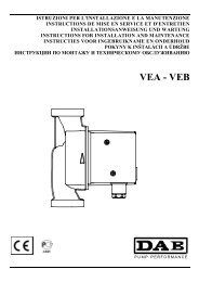
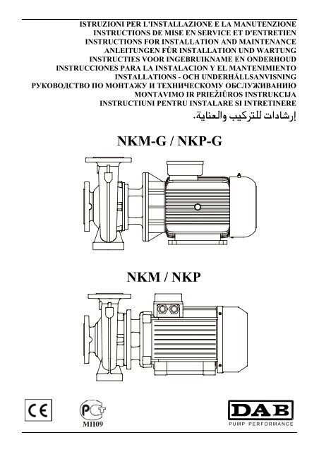
ISTRUZIONI PER L'INSTALLAZIONE E LA MANUTENZIONE<br />
INSTRUCTIONS DE MISE EN SERVICE ET D'ENTRETIEN<br />
INSTRUCTIONS FOR INSTALLATION AND MAINTENANCE<br />
ANLEITUNGEN FÜR INSTALLATION UND WARTUNG<br />
INSTRUCTIES VOOR INGEBRUIKNAME EN ONDERHOUD<br />
INSTRUCCIONES PARA LA INSTALACION Y EL MANTENIMIENTO<br />
INSTALLATIONS - OCH UNDERHÅLLSANVISNING<br />
РУКОВОДСТВО ПО МОНТАЖУ И ТЕХНИЧЕСКОМУ ОБСЛУЖИВАНИЮ<br />
MONTAVIMO IR PRIEŽIŪROS INSTRUKCIJA<br />
INSTRUCTIUNI PENTRU INSTALARE SI INTRETINERE<br />
.ª¦Bl{A¥ J¦yZK{{ LAXBcZG<br />
<strong>NKM</strong>-G / <strong>NKP</strong>-G<br />
<strong>NKM</strong> / <strong>NKP</strong>
<strong>NKM</strong> 32-125.1 <strong>NKM</strong> 32-125 <strong>NKM</strong> 32-160.1 <strong>NKM</strong> 32-160 <strong>NKM</strong> 32-200.1 <strong>NKM</strong> 32-200<br />
<strong>NKM</strong> 40-125 <strong>NKM</strong> 40-160 <strong>NKM</strong> 40-200 <strong>NKM</strong> 40-250 <strong>NKM</strong> 50-125 <strong>NKM</strong> 50-160<br />
<strong>NKM</strong> 50-200 <strong>NKM</strong> 50-250<br />
<strong>NKM</strong>-G 32-125.1 <strong>NKM</strong>-G 32-125 <strong>NKM</strong>-G 32-160.1 <strong>NKM</strong>-G 32-160 <strong>NKM</strong>-G 32-200.1<br />
<strong>NKM</strong>-G 32-200 <strong>NKM</strong>-G 40-125 <strong>NKM</strong>-G 40-160 <strong>NKM</strong>-G 40-200 <strong>NKM</strong>-G 40-250<br />
<strong>NKM</strong>-G 50-125 <strong>NKM</strong>-G 50-160 <strong>NKM</strong>-G 50-200 <strong>NKM</strong>-G 50-250 <strong>NKM</strong>-G 65-125<br />
<strong>NKM</strong>-G 65-160 <strong>NKM</strong>G- 65-200 <strong>NKM</strong>-G 65-250 <strong>NKM</strong>-G 65-315 <strong>NKM</strong>-G 80-160<br />
<strong>NKM</strong>-G 80-200 <strong>NKM</strong>-G 80-250 <strong>NKM</strong>-G 80-315 <strong>NKM</strong>-G 100-200 <strong>NKM</strong>-G 100-250<br />
<strong>NKM</strong>-G 100-315 <strong>NKM</strong>-G 125-250 <strong>NKM</strong>-G 150-200<br />
<strong>NKM</strong>-GE 32-125.1 <strong>NKM</strong>-GE 32-125 <strong>NKM</strong>-GE 32-160.1 <strong>NKM</strong>-GE 32-160 <strong>NKM</strong>-GE 32-200.1<br />
<strong>NKM</strong>-GE 32-200 <strong>NKM</strong>-GE 40-125 <strong>NKM</strong>-GE 40-160 <strong>NKM</strong>-GE 40-200 <strong>NKM</strong>-GE 40-250<br />
<strong>NKM</strong>-GE 50-125 <strong>NKM</strong>-GE 50-160 <strong>NKM</strong>-GE 50-200 <strong>NKM</strong>-GE 50-250 <strong>NKM</strong>-GE 65-125<br />
<strong>NKM</strong>-GE 65-160 <strong>NKM</strong>-GE 65-200 <strong>NKM</strong>-GE 65-250 <strong>NKM</strong>-GE 65-315 <strong>NKM</strong>-GE 80-160<br />
<strong>NKM</strong>-GE 80-200 <strong>NKM</strong>-GE 80-250 <strong>NKM</strong>-GE 100-200<br />
<strong>NKP</strong> 32-125.1 <strong>NKP</strong> 32-125 <strong>NKP</strong> 32-160.1 <strong>NKP</strong> 32-160 <strong>NKP</strong> 32-200.1 <strong>NKP</strong> 32-200<br />
<strong>NKP</strong> 40-125 <strong>NKP</strong> 40-160 <strong>NKP</strong> 40-200 <strong>NKP</strong> 40-250 <strong>NKP</strong> 50-125 <strong>NKP</strong> 50-160<br />
<strong>NKP</strong> 50-200 <strong>NKP</strong> 50-250<br />
<strong>NKP</strong>-G 32-125.1 <strong>NKP</strong>-G 32-125 <strong>NKP</strong>-G 32-160.1 <strong>NKP</strong>-G 32-160 <strong>NKP</strong>-G 32-200.1<br />
<strong>NKP</strong>-G 32-200 <strong>NKP</strong>-G 40-125 <strong>NKP</strong>-G 40-160 <strong>NKP</strong>-G 40-200 <strong>NKP</strong>-G 40-250<br />
<strong>NKP</strong>-G 50-125 <strong>NKP</strong>-G 50-160 <strong>NKP</strong>-G 50-200 <strong>NKP</strong>-G 50-250 <strong>NKP</strong>-G 65-125<br />
<strong>NKP</strong>-G 65-160 <strong>NKP</strong>-G 65-200 <strong>NKP</strong>-G 80-160 <strong>NKP</strong>-G 80-200<br />
<strong>NKP</strong>-GE 32-125.1 <strong>NKP</strong>-GE 32-125 <strong>NKP</strong>-GE 32-160.1 <strong>NKP</strong>-GE 32-160 <strong>NKP</strong>-GE 32-200.1<br />
<strong>NKP</strong>-GE 32-200 <strong>NKP</strong>-GE 40-125 <strong>NKP</strong>-GE 40-160 <strong>NKP</strong>-GE 50-125 <strong>NKP</strong>-GE 50-160<br />
<strong>NKP</strong>-GE 65-125
DICHIARAZIONE DI CONFORMITÀ<br />
La Ditta DAB PUMPS s.p.a. - Via M. Polo,14 - Mestrino (PD) -<br />
ITALY - sotto la propria esclusiva responsabilità dichiara che i<br />
prodotti summenzionati sono conformi a:<br />
− Direttiva del Consiglio n° 98/37/CE concernente il<br />
riavvicinamento delle legislazioni degli Stati membri CEE<br />
relative alle macchine e successive modifiche.<br />
− Direttiva della Compatibilità elettromagnetica 89/336 e<br />
successive modifiche.<br />
− Direttiva Bassa Tensione 73/23 e successive modifiche.<br />
DECLARATION OF CONFORMITY<br />
The Company DAB PUMPS s.p.a. - Via M. Polo,14 - Mestrino<br />
(PD) - ITALY - declares under its own responsibility that the<br />
above-mentioned products comply with:<br />
− Council Directive no. 98/37/CE concerning the reconciliation<br />
of the legislations of EEC Member Countries with relation to<br />
machines and subsequent modifications.<br />
− Directive on electromagnetic compatibility no. 89/336 and<br />
subsequent modifications.<br />
− Directive on low voltage no. 73/23 and subsequent<br />
modifications.<br />
CONFORMITEITSVERKLARING<br />
De firma DAB PUMPS s.p.a. - Via M. Polo, 14 Mestrino (PD) -<br />
Italië, verklaart hierbij onder haar verantwoording dat<br />
hierbovengenoemde produkten conform zijn aan<br />
− de Richtlijn van de Raad nr. 98/37/CE betreffende harmonisatie<br />
van de wetgeving in de EEG-lidstaten t.a.v. machines en<br />
daaropvolgende wijzigingen.<br />
− De richtlijnen van de elektromagnetische overeenstemming<br />
89/336 en latere veranderingen.<br />
− De richtlijnen voor lage druk 73/23 en latere veranderingen.<br />
FÖRSÄKRAN OM ÖVERENSSTÄMMELSE<br />
Bolaget DAB PUMPS s.p.a. - Via M. Polo,14 - Mestrino (PD) -<br />
ITALIEN - intygar på eget ansvar att ovannämnda produkter är i<br />
enlighet med:<br />
− Rådets direktiv nr. 98/37/CE och efterföljande ändringar som<br />
innehåller en jämkning av EU-ländernas lagstiftning<br />
beträffande maskiner.<br />
− EMC-direktivet nr. 89/336 och efterföljande ändringar.<br />
− Lågspänningsdirektiv nr. 73/23 och efterföljande<br />
ändringar.<br />
ATITIKTIES DEKLARACIJA<br />
DAB PUMPS s.p.a. – Via M. Polo, 14 – Mestrino (PD) – Italija –<br />
garantuoja, kad šiame leidinyje išvardyti gaminiai atitinka:<br />
− Tarybos direktyvą Nr. 98/37/CE, bei jos pataisas suderintais<br />
su ES valstybių įstatymais, susijusiais su mechanizmais.ù<br />
− Elektromagnetinio suderinamumo direktyvą Nr. 89/336, bei<br />
jos pataisas.<br />
− Įrenginių skirtų naudoti tam tikros įtampos ribose<br />
direktyvą Nr. 73/23, bei jos pataisas.<br />
ªwIBi} ©XB¢c<br />
DAB PUMPS S.p.A. ªyZc{A<br />
VIA M. POLO 14<br />
MESTRINO (PD)<br />
ITALY<br />
:«{G ªwIBi} Lle ¤½kC ©Z¥yY}{A LBOK}{A áDI X¢cK ªeBU{A B¢K¦{¥»a} LRK<br />
.LAZ¦¦pK á} £wR{ B}¥ 98/37/CE ~vZ WZ»}{A −AZ`¥{A b{O} á¥Bv -<br />
.LAZ¦¦pK á} £wR{ B}¥ 89/336 ª¦a¦iBp}¥ZKy{ÂA ªwIBi}{BI fBU{A á¥Bw{A -<br />
.LAZ¦¦pK á} £wR{ B}¥ 73/23 htU}{A X¢O{BI fBU{A á¥Bw{A -<br />
DÈCLARATION DE CONFORMITÈ<br />
L'entreprise DAB PUMPS s.p.a. - Via M. Polo,14 - Mestrino (PD)<br />
- ITALIE - déclare sous sa responsabilité exclusive que les produits<br />
susmentionnés sont conformes à:<br />
− la Directive du Conseil n° 98/37/CE concernant<br />
l'harmonisation des législations des Etats membres de la CEE<br />
relatives aux machines et ses modifications successives.<br />
− la Directive de la compatibilité électromagnétique 89/336 et ses<br />
modifications successives.<br />
− la Directive basse tension 73/23 et ses modifications<br />
successives.<br />
KONFORMITÄTSERKLÄRUNG<br />
Die Firma DAB PUMPS s.p.a. - Via M. Polo,14 - Mestrino (PD) -<br />
ITALY - erklärt unter ihrer eigenen, ausschließlichen<br />
Verantwortung, daß die genannten Produkte den folgenden<br />
Verordnungen entsprechen:<br />
− Ratsverordnung Nr. 98/37/CE über die Angleichung der<br />
Gesetzgebung der CEE-Staaten über Maschinen und folgende<br />
Abänderungen.<br />
− Verordnung über die elektromagnetische Kompatibilität 89/336<br />
und folgende Abänderungen.<br />
− Verordnung über Schwachstrom 73/23 und folgende<br />
Abänderungen.<br />
DECLARACION DE CONFORMIDAD<br />
La Empresa DAB PUMPS s.p.a. - Via M. Polo,14 - Mestrino (PD)<br />
- ITALY - bajo su propia y exclusiva responsabilidad declara que<br />
los productos anteriormente mencionados respetan:<br />
− Las Directrices del Consejo n° 98/37/CE referentes a la<br />
homogeneización de las legislaciones de los Estados miembros<br />
de la CEE relativas a las máquinas y sucesivas modificaciones.<br />
− Directriz de la Compatibilidad electromagnética 89/336 y<br />
sucesivas modificaciones.<br />
− Directriz Baja Tensión 73/23 y sucesivas modificaciones.<br />
1<br />
ЗАЯВЛЕНИЕ О СООТВЕТСТВИИ<br />
Фирма DAB PUMPS s.p.a. – Via Marco Polo, 14 Mestrino (PD)<br />
ИТАЛИЯ- под собственную исключительную ответственность<br />
заявляет, что вышеуказанные агрегаты соответствуют:<br />
− Директиве Совета n° 98/37/CE касательно сближения<br />
законодательств Государств членов ЕЭС в области<br />
агрегатов и последющим поправкам.<br />
− Директиве об Электромагнитной совместимости 89/336 и<br />
последующим поправкам.<br />
− Директиве о низком напряжении 73/23 и последующим<br />
поправкам.<br />
DECLARATIE DE CONFORMITATE<br />
Firma DAB PUMPS s.p.a. – Via M. Polo, 14 – Mestrino (PD) –<br />
Italia – declara pe propria raspundere ca produsele mentionate mai<br />
sus in conformitate cu:<br />
− Directiva Consiliului nr. 98/37/CE privind armonizarea<br />
legislatiilor Statelor membre CEE referitoare la masini cu<br />
modificarile sale ulterioare.<br />
− Directiva referitoare la compatibilitatea electromagnetica<br />
89/336 si modificarile ulterioare.<br />
− Directiva referitoare la Joasa Tensiune 73/23 si modificarile<br />
ulterioare.<br />
Mestrino (PD), 07 Gennaio 1998<br />
Attilio Conca<br />
Legale Rappresentante<br />
Legal Representative
Collegamento TRIFASE per motori<br />
Branchement TRIPHASE pour moteurs<br />
THREE-PHASE motor connection<br />
Aansluiting TRIPLEFASE voor motoren<br />
DREIPHASIGER Anschluß für Motoren<br />
Conexión TRIFASICA para motores<br />
TREFAS elanslutning för motorer<br />
ТРЕХФАЗНОЕ соединение двигателей<br />
TRIFAZIO variklio pajungimas<br />
Conexiune TRIFAZICA pentru motor<br />
LByZR}{{ Z¥i{A §M½M |Be¦G<br />
3 ~ 230/400 V 3 ~ 400 ∆ V<br />
W 2<br />
U 2<br />
V 2<br />
W 2 U 2 V 2<br />
U 1 V 1 W 1<br />
W 1<br />
W 2 U 2<br />
U 1<br />
V 2<br />
V 1 W 1<br />
230V Linea - Ligne 400V<br />
Line - Lijn<br />
Linie - Línea - Ledning<br />
Линия 230В 400 В - Linija - Linie<br />
V 400 iU V230<br />
Linea - Ligne<br />
Line - Lijn<br />
Linie - Línea - Ledning<br />
Линия - Linija - Linie<br />
iU<br />
U 1<br />
U 1<br />
U 1<br />
V 1<br />
W 1<br />
Collegamento a TRIANGOLO<br />
Branchement TRIANGLE<br />
DELTA starting<br />
Driehoekaansluiting<br />
DREIECK-Schaltung<br />
Conexión de TRIÁNGULO<br />
DELTA-anslutning<br />
Соединение на ТРЕУГОЛНИК<br />
Trikampis jungimas<br />
Conexiune TRIUNGHI<br />
N{M}I |Be¦ÂA<br />
V 1<br />
W 1<br />
Collegamento a STELLA<br />
Branchement ETOILE<br />
STAR starting<br />
Steraansluiting<br />
STERN-Schaltung<br />
Conexión de ESTRELLA<br />
Y-anslutning<br />
Соединение на ЗВЕЗДУ<br />
Jungimas žvaigžde<br />
Conexiune STEA<br />
ª}OI |Be¦ÂA<br />
V 1<br />
W 1<br />
Collegamento a TRIANGOLO<br />
Branchement TRIANGLE<br />
DELTA starting<br />
Driehoekaansluiting<br />
DREIECK-Schaltung<br />
Conexión de TRIÁNGULO<br />
DELTA-anslutning<br />
Соединение на ТРЕУГОЛНИК<br />
Trikampis jungimas<br />
Conexiune TRIUNGHI<br />
N{M}I |Be¦ÂA<br />
3
ENGLISH<br />
CONTENTS<br />
page<br />
1. GENERAL 20<br />
1.1. Pump description 20<br />
2. APPLICATIONS 21<br />
3. PUMPED FLUIDS 21<br />
4. TECHNICAL DATA AND RANGE OF USE 21<br />
5. MANAGEMENT 21<br />
5.1. Storage 21<br />
5.2. Transport 21<br />
5.3. Dimensions and weights 21<br />
6. WARNINGS 21<br />
6.1. Skilled personnel 21<br />
6.2. Safety 22<br />
6.3 Checking pump/motor shaft rotation 22<br />
6.4 New systems 22<br />
6.5 Responsibility 22<br />
6.6 Protections 22<br />
6.6.1 Moving parts 22<br />
6.6.2 Noise level 22<br />
6.6.3 Hot and cold parts 22<br />
7. INSTALLATION 22<br />
8. ELECTRICAL CONNECTION 24<br />
9. STARTING UP 24<br />
10. STARTING/STOPPING 24<br />
11. PRECAUTIONS 25<br />
12. MAINTENANCE AND CLEANING 25<br />
12.1 Periodic checks 25<br />
12.2 Shaft seal 25<br />
12.2.1 Mechanical seal 25<br />
12.3 Changing the seal 26<br />
12.3.1 Preparing disassembly 26<br />
12.3.2 Changing the mechanical seal 26<br />
13. MODIFICATIONS AND SPARE PARTS 26<br />
14. TROUBLESHOOTING 26<br />
15. PART DRAWINGS 102<br />
1. GENERAL<br />
Read this documentation carefully before installation. It contains fundamental instructions to help<br />
you get to know the pump so that you can make the best use of its various possibilities of<br />
application. Observing these indications will ensure long life of the pump parts and avoid risks. The<br />
manual must always be kept within reach in the place where the machine is to be used.<br />
Installation and functioning must comply with the safety regulations in force in the country in which the<br />
Product is installed. The entire operation must be carried out in a workmanlike manner, exclusively by<br />
skilled personnel (paragraph 6.1), in possession of the technical qualifications indicated by the standards<br />
in force. Failure to comply with the safety regulations not only causes risk to personal safety and damage<br />
to the equipment, but invalidates every right to assistance under guarantee. The pump may be installed<br />
in either horizontal or vertical position, as long as the motor is always above the pump.<br />
1.1. Pump description:<br />
Example: <strong>NKM</strong> - G 50 - 250 / 263 A W / BAQE / 4 / 4<br />
Type range:<br />
TWO-POLE MOTOR = P<br />
FOUR-POLE MOTOR = M<br />
With standardised motor and coupling<br />
Nominal diameter of discharge port<br />
Nominal impeller diameter<br />
Actual impeller diameter<br />
Cod for materials:<br />
A = Cast iron<br />
B = Cast iron with bronze impeller<br />
Wear rings ( only when there is )<br />
Code for shaft seal:<br />
Motor power in kW<br />
Poles:<br />
4 = 4 poles<br />
2 = 2 poles<br />
20
ENGLISH<br />
2. APPLICATIONS<br />
Single-stage stub shaft type centrifugal motor-driven pumps with a spiral body, dimensions in accordance with DIN 24255 -<br />
EN 733 and flanged DIN 2533 (DIN 2532 per DN 200). Designed and built with advanced characteristics, they are<br />
outstanding for their particular performances which ensure maximum yield while guaranteeing absolute reliability and sturdy<br />
construction. They cover a wide range of applications, such as water supply, circulation of hot and cold water in heating, airconditioning<br />
and refrigerating systems, transfer of liquids in agriculture, market gardening and industry. Also suitable for use<br />
in fire-fighting sets.<br />
3. PUMPED FLUIDS<br />
The machine has been designed and built for pumping clean, pure and aggressive fluids, on<br />
condition that in the latter case the compatibility of the pump construction materials is checked<br />
and that the motor used has sufficient power for the specific gravity and the viscosity of the<br />
fluid.<br />
4. TECHNICAL DATA AND RANGE OF USE<br />
Pump<br />
− Liquid temperature range: from -10°C to +140°C<br />
− Rotation speed: 1450-2900 1/min<br />
− Flow rate:<br />
from 1 m 3 /h to 500 m³/h depending on the model<br />
− Head up – Hmax (m): pag. 105<br />
− Maximum environment temperature: +40°C<br />
− Storage temperature: -10°C +40°C<br />
− Relative humidity of the air: max 95%<br />
− Maximum working pressure (including any pressure at intake): 16 Bar - 1600 kPa (for DN 200 max 10 Bar-1000 kPa)<br />
− Weight: See plate on package<br />
− Dimensions: see table on page 96-97-99<br />
Motor<br />
− Supply voltage: 3 x 230-400 V 50/60Hz up to 4 KW inclusive<br />
3 x 400 V ∆ 50/60Hz over 4 KW<br />
− Degree of motor protection : IP55<br />
− Thermal class : F<br />
− Absorbed power : see electric data plate<br />
− Motor construction : in conformity with Standards CEI 2 - 3<br />
− Class AM line fuses: see table 4.1. page 95<br />
If a fuse trips which protects a three-phase motor, it is recommended to change the<br />
other two fuses as well, not only the one that is burnt-out.<br />
5. MANAGEMENT<br />
5.1. Storage<br />
All the pumps/electropumps must be stored indoors, in a dry, vibration-free and dust-free environment, possibly with constant<br />
air humidity. They are supplied in their original packaging and must remain there until the time of installation, with the intake<br />
and delivery mouths closed with the special adhesive disc supplied. In the case of long storage, or if the pump is stored after a<br />
certain period of operation, only the parts made of low-percentage alloy materials, such as cast iron GG-25, GGG-40 which<br />
have been wet with the pumped fluid, should be kept in the special preserving mediums available on the market.<br />
5.2. Transport<br />
Avoid subjecting the products to needless jolts or collisions.<br />
To lift and transport the unit, use lifting equipment and the pallet supplied<br />
standard (if applicable).<br />
Use suitable hemp or synthetic ropes only if the part can be easily slung, as<br />
indicated in fig.5.2. If an eyebolt is provided on the motor, it must not be<br />
used for lifting the whole assembly. (fig. 5.2.)<br />
5.3. Dimensions and weights<br />
The adhesive label on the package indicates the total weight of the electropump. The dimensions are given on page 96-97-99.<br />
6. WARNINGS<br />
6.1. Skilled technical personnel<br />
It is advisable that installation be carried out by skilled personnel in possession of the technical<br />
qualifications required by the specific legislation in force.<br />
The term skilled personnel means persons whose training, experience and instruction, as well as their<br />
knowledge of the respective standards and requirements for accident prevention and working conditions, have<br />
been approved by the person in charge of plant safety, authorizing them to perform all the necessary activities,<br />
during which they are able to recognize and avoid all dangers. (Definition for technical personnel IEC 364).<br />
21
ENGLISH<br />
6.2. Safety<br />
6.2.1. Use is allowed only if the electric system is in possession of safety precautions in accordance with the regulations<br />
in force in the country where the product is installed (for Italy, CEI 64/2).<br />
6.3. Checking pump/motor shaft rotation<br />
Before installing the electropump, it is good practice to check that the pump shaft and/or the motor are moving freely. For<br />
this purpose, if the pumps are supplied without a motor, check them by turning the pump coupling by hand. If the electropump<br />
is supplied as a complete unit, check by turning the coupling by hand after having removed the coupling cover. When you<br />
have finished checking, put the coupling cover back in its original position.<br />
Do not force the shaft or the fan of the motor (if supplied) with pliers or other tools<br />
to try to free the pump, but look for the cause of the blockage.<br />
6.4. New systems<br />
Before running new systems the valves, pipes, tanks and couplings must be cleaned accurately. Often welding waste, flakes of<br />
oxide or other impurities fall off after only a certain period of time. To prevent them from getting into the pump they must be<br />
caught by suitable filters. The free surface of the filter must have a section at least 3 times larger than the section of the pipe<br />
on which the filter is fitted, so as not to create excessive load losses. We recommend the use of TRUNCATED CONICAL<br />
filters made of corrosion-resistant materials (SEE DIN 4181):<br />
5 1 2 3 4<br />
(Filter for intake pipe)<br />
1) Filter body<br />
2) Narrow mesh filter<br />
3) Differential pressure gauge<br />
4) Perforated sheet<br />
5) Pump intake aperture<br />
6.5. Responsibility<br />
The Manufacturer does not vouch for correct operation of the pumps if they are tampered with or<br />
modified, run outside the recommended work range or in contrast with the other instructions given in<br />
this manual.<br />
The Manufacturer declines all responsibility for possible errors in this instructions manual, if due to<br />
misprints or errors in copying. The company reserves the right to make any modifications to products<br />
that it may consider necessary or useful, without affecting the essential characteristics.<br />
6.6. Protections<br />
6.6.1. Moving parts<br />
In accordance with accident-prevention regulations, all moving parts (fans, couplings, etc.) must be accurately<br />
protected with special devices (fan covers, coupling covers) before operating the pump.<br />
During pump operation, keep well away from the moving parts (shaft, fan, etc.) unless it is<br />
absolutely necessary, and only then wearing suitable clothing as required by law, to avoid being<br />
caught.<br />
6.6.2. Noise level<br />
The noise levels of pumps with standard supply motors are indicated in table 6.6.2 on page 95. Remember that, in<br />
cases where the LpA noise levels exceed 85 dB(A), suitable HEARING PROTECTION must be used in the place<br />
of installation, as required by the regulations in force.<br />
6.6.3. Hot and cold parts<br />
As well as being at high temperature and high pressure, the fluid in the system may also be in<br />
the form of steam! DANGER OF BURNING ! ! !<br />
It may be dangerous even to touch the pump or parts of the system.<br />
If the hot or cold parts are a source of danger, they must be accurately protected to avoid contact<br />
with them.<br />
6.6.4. Any leaks of dangerous or harmful liquids (for example, from the shaft seal) must be conveyed and disposed of in<br />
accordance with the regulations in force so as not to cause a risk or damage to persons and to the environment.<br />
7. INSTALLATION<br />
The electropump must be fitted in a well ventilated place, with an environment temperature not exceeding 40°C.<br />
As they have degree of protection IP55, the electropumps may be installed in dusty and damp environments. If<br />
installed in the open, generally it is not necessary to take any particular steps to protect them against unfavourable<br />
weather conditions.<br />
If the unit is installed in a location where there is a risk of explosion, the local regulations on "Ex" protection must<br />
be respected, using only suitable motors.<br />
22
ENGLISH<br />
7.1. Foundation<br />
The buyer is fully responsible for preparing the foundation which must be made in conformity with the<br />
dimensions shown on page 96-97-99. Metal foundations must be painted to avoid corrosion; they must be level<br />
and sufficiently rigid to withstand any stress. Their dimensions must be calculated to avoid the occurrence of<br />
vibrations due to resonance.<br />
With concrete foundations, care must be taken to ensure that the concrete has set firmly and is completely dry<br />
before placing the unit on it. The surface that it sits on must be perfectly flat and horizontal. After the pump has<br />
been positioned on the foundation, check with a spirit level to ensure that it is sitting perfectly level. If not,<br />
suitable shims must be inserted (see pag. 96-97-99)<br />
7.2. Connecting the pipes<br />
Ensure that the metal pipes do not transmit excess force to the pump apertures, so as to avoid causing deformations or<br />
breakages. Any expansion due to the heat of the pipes must be compensated with suitable precautions to avoid<br />
weighing down on the pump. The counterflanges of the pipes must be parallel to the flanges of the pump.<br />
To reduce noise to a minimum it is advisable to fit vibration-damping couplings on the intake and delivery pipes.<br />
It is always good practice to place the pump as close as possible to the liquid to be pumped. It is advisable to<br />
use a suction pipe with a diameter larger than that of the intake aperture of the electropump. If the head at intake is<br />
negative, it is indispensable to fit a foot valve with suitable characteristics at intake. Irregular passages between<br />
the diameters of the pipes and tight curves considerably increase load losses. Any passage from a pipe with a<br />
small diameter to one with a larger diameter must be gradual. Usually the length of the passage cone must be 5 to<br />
7 times the difference in diameter.<br />
Check accurately to ensure that the joins in the intake pipe do not allow air infiltrations. Ensure that the gaskets<br />
between flanges and counterflanges are well centred so as not to create resistances to the flow in the pipes. To<br />
prevent the formation of air pockets, the intake pipe must slope slightly upwards towards the pump.<br />
If more than one pump is installed, each pump must have its own intake pipe. The only exception is the reserve<br />
pump (if envisaged) which, as it starts up only in the case of breakdown of the main pump, ensures the operation<br />
of only one pump for each intake pipe.<br />
Interception valves must be fitted upstream and downstream from the pump so as to avoid having to drain the<br />
system when carrying out pump maintenance.<br />
The pump must not be operated with the interception valves closed, as in these conditions there<br />
would be an increase in the temperature of the liquid and the formation of vapour bubbles inside the<br />
pump, leading to mechanical damage. If there is any possibility of the pump operating with the<br />
interception valves closed, provide a by-pass circuit or a drain leading to a liquid recovery tank<br />
(following the requirements of local legislation concerning toxic fluids).<br />
7.3. Calculating the NPSH<br />
To guarantee good operation and maximum performance of the electropump, it is necessary to know the level of<br />
the N.P.S.H. (Net Positive Suction Head) of the pump concerned, so as to determine the suction level Z1. The<br />
curves for the N.P.S.H. of the various pumps may be found in the technical catalogue.<br />
This calculation is important because it ensures that the pump can operate correctly without cavitation phenomena<br />
which occur when, at the impeller intake, the absolute pressure falls to values that allow the formation of vapour<br />
bubbles in the fluid, so that the pump works irregularly with a fall in head. The pump must not cavitate because,<br />
as well as producing considerable noise similar to metallic hammering, it would cause irreparable damage to the<br />
impeller.<br />
To determine the suction level Z1, the following formula must be applied:<br />
Z1 = pb - rqd. N.P.S.H. - Hr - correct pV<br />
where:<br />
Z1 = difference in level in metres between the axis of the pump and the free surface of the liquid to be pumped<br />
pb = barometric pressure in mcw of the place of installation (fig. 6 on page 101)<br />
NPSH = net load at intake of the place of work (see characteristic curves in the catalogue)<br />
Hr = load loss in metres on the whole intake duct (pipe - curves - foot valves)<br />
pV = vapour tension in metres of the liquid in relation to the temperature expressed in °C<br />
(see fig. 7 on page 101)<br />
Example 1: installation at sea level and fluid at t = 20°C<br />
Required N.P.S.H. : 3.25 m<br />
Pb :<br />
10.33 mcw<br />
Hr:<br />
2.04 m<br />
t: 20°C<br />
PV:<br />
0.22 m<br />
Z1<br />
10.33 - 3.25 - 2.04 - 0.22 = 4.82 approx.<br />
Example 2: installation at a height of 1500 m and fluid at t = 50°C<br />
required N.P.S.H. : 3.25 m<br />
pb :<br />
8.6 mcw<br />
Hr:<br />
2.04 m<br />
t: 50°C<br />
pV:<br />
1.147 m<br />
Z1<br />
8.6 - 3.25 - 2.04 - 1.147 = 2.16 approx.<br />
23
ENGLISH<br />
Example 3: installation at sea level and fluid at t = 90°C<br />
required N.P.S.H. : 3.25 m<br />
pb :<br />
10.33 mcw<br />
Hr:<br />
2.04 m<br />
t: 90°C<br />
pV:<br />
7.035 m<br />
Z1<br />
10.33 - 3.25 - 2.04 - 7.035 = -1.99 approx.<br />
In the last case, in order to operate correctly the pump must be fed with a positive head of 1.99 - 2 m, that is the free surface of<br />
the water must be 2 m higher than the axis of the pump.<br />
N.B.: it is always good practice to leave a safety margin (0.5 m in the case of cold water) to allow for<br />
errors or unexpected variations in the estimated data. This margin becomes especially important with<br />
liquids at a temperature close to boiling point, because slight temperature variations cause considerable<br />
differences in the working conditions. For example in the third case, if instead of 90°C the water<br />
temperature reaches 95°C at any time, the head required by the pump would no longer be 1.99 but 3.51<br />
metres.<br />
7.4. Connecting auxiliary systems and measuring instruments.<br />
The realization and connection of any auxiliary systems (washing liquid, seal cooling fluid, dripping liquid) must<br />
be considered when designing the system. These connections are necessary for better and longer lasting pump<br />
operation.<br />
In order to ensure continuous monitoring of the pump functions, it is recommended to install a vacuum pressure<br />
gauge don the intake side and a pressure gauge on the delivery side. To check the motor load the installation of an<br />
ammeter is advised.<br />
8. ELECTRICAL CONNECTION<br />
Caution: always follow the safety regulations!<br />
Scrupulously follow the wiring diagrams inside the terminal board box and<br />
those on page 3 of this manual.<br />
8.1. The electrical connections must be made exclusively by skilled personnel (see paragraph 6.1) as required by<br />
the safety regulations in force.<br />
The requirements of the electric energy supply company must be scrupulously complied with.<br />
In the case of three-phase motors with star-delta start, ensure that the switch-over time from star to delta is as short<br />
as possible and that it falls within table 8.1 on page 96.<br />
8.2. Before opening the terminal board and working on the pump, ensure that the power has been switched off.<br />
8.3. Check the mains voltage before making any connection. If it is the same as the voltage on the data plate, proceed<br />
to connect the wires to the terminal board, giving priority to the earth lead.<br />
8.4. ENSURE THAT THE EARTH SYSTEM IS EFFICIENT AND THAT THERE IS THE POSSIBILITY OF<br />
MAKING A GOOD CONNECTION.<br />
8.5. The pumps must always be connected to an external switch.<br />
8.6. The motors must be protected with special remote-control motor-protectors calibrated for the current shown on the<br />
plate.<br />
9. STARTING UP<br />
9.1. Before starting the pump, check that:<br />
- the pump has been properly primed, filling the pump body completely. This ensures that the<br />
pump immediately starts to work regularly and that the seal (mechanical seal or stuffing box<br />
seal) is well lubricated. Dry operation causes irreparable damage to the mechanical seal and<br />
the stuffing box seal.<br />
- the auxiliary circuits have been correctly connected;<br />
- all the moving parts have been protected with suitable safety systems;<br />
- the electrical connection has been made as indicated previously;<br />
10. STARTING/STOPPING<br />
10.1. STARTING<br />
10.1.1. Fully open the gate valve on intake and keep the one on delivery almost closed.<br />
10.1.2. Switch on the power and check that the motor is turning in the right direction, that is clockwise when viewed from<br />
the fan side. This check must also be performed after having fed the pump, activating the main switch with a fast<br />
start-stop sequence. If the motor is turning in the wrong direction, invert any two phase leads, after having<br />
disconnected the pump from the mains.<br />
24
ENGLISH<br />
10.1.3. Once the hydraulic circuit has been completely filled with liquid, gradually open the delivery gate valve until its<br />
maximum allowed opening. The motor's energy consumption must be checked and compared with the value<br />
shown on the data plate, especially in cases where the pump has intentionally been given a reduced power<br />
motor (check the design characteristics).<br />
10.1.4. With the pump running, check the supply voltage at the motor terminals, which must not differ from the rated<br />
value by +/- 5%<br />
10.2. STOPPING<br />
Close the interception device on the delivery pipe. If there is a check device on the delivery pipe, the interception valve<br />
on the delivery side may remain open as long as there is back pressure downstream from the pipe.<br />
If hot water is to be pumped, arrange that the pump can be stopped only after having excluded the source of heat<br />
and let sufficient time elapse to allow the liquid temperature to drop to acceptable values, so as not to create<br />
excessive temperature increases inside the pump body.<br />
For a long period of inactivity, close the interception device on the intake pipe and, if supplied, all the auxiliary<br />
control connections. To guarantee maximum system functionality it will be necessary to arrange for brief running<br />
periods (5 - 10 min) at intervals of 1 to 3 months.<br />
If the pump is removed from the system and stored, proceed as indicated in par.5.1<br />
11. PRECAUTIONS<br />
11.1. The electropump should not be started an excessive number of times in one hour. The maximum admissible value<br />
is as follows:<br />
TYPE OF PUMP<br />
MAXIMUM NUMBER OF STARTS PER HOUR<br />
THREE-PHASE MOTORS UP TO AND INCLUDING 4 kW 100<br />
THREE-PHASE MOTORS OVER 4 kW 20<br />
11.2. DANGER OF FROST: When the pump remains inactive for a long time at temperatures of less than 0°C, the<br />
pump body must be completely emptied through the drain cap (26), to prevent possible cracking of the hydraulic<br />
components.<br />
Check that the leakage of liquid does not damage persons or things, especially in plants that<br />
use hot water.<br />
Do not close the drainage cap until the pump is to be used again.<br />
When restarting after long periods of inactivity it is necessary to repeat the operations described above in the<br />
paragraphs "WARNINGS" and "STARTING UP".<br />
11.3. To avoid needless motor overloads, accurately check that the density of the pumped liquid corresponds to that<br />
used in the design phase: remember that the power absorbed by the pump increases in proportion to the<br />
density of the liquid carried.<br />
12. MAINTENANCE AND CLEANING (instructions referring to the parts drawings on page 102-103)<br />
The electropump can only be dismantled by competent skilled personnel, in possession of the<br />
qualifications required by the legislation in force. In any case, all repair and maintenance<br />
jobs must be carried out only after having disconnected the pump from the power mains.<br />
Ensure that it cannot be switched on accidentally.<br />
If the liquid has to be drained to carry out maintenance, ensure that the liquid coming out<br />
cannot harm persons or things, especially in systems using hot water.<br />
The legal requirements on the disposal of any harmful fluids must also be complied with.<br />
After a long period of operation there may be difficulties in removing the parts in contact with<br />
water: to do this, use a special solvent available on the market and, where possible, use a<br />
suitable extractor.<br />
Do not force the parts with unsuitable tools.<br />
12.1. Periodic checks<br />
In normal operation, the pump does not require any kind of maintenance. However, from time to time it is<br />
advisable to check current absorption, the manometric head with the aperture closed and the maximum flow rate,<br />
which will enable you to have advance warning of any faults or wear. If possible, arrange for programmed<br />
maintenance so that problem-free operation may be ensured with minimum expense and reduced machine down<br />
times, thus avoiding long and costly repairs.<br />
12.2. Shaft seal<br />
12.2.1. Mechanical seal<br />
Normally no checking is required. Just ensure that there are no leaks of any kind. If leaks are present, change the<br />
seal as described in par.12.3.1<br />
25
ENGLISH<br />
12.3. Changing the seal<br />
12.3.1. Preparing disassembly<br />
1. Switch off the electric power supply and ensure that it cannot be switched on accidentally.<br />
2. Close the interception devices on intake and delivery.<br />
3. If hot liquids have been pumped, wait until the pump body returns to room temperature.<br />
4. Empty the pump body by means of the drainage caps, taking particular care if harmful fluids have been<br />
pumped (observe the legal requirements in force).<br />
5. Dismantle any auxiliary connections provided.<br />
12.3.2. Changing the mechanical seal<br />
Slacken the nuts ref. (190) from the stud bolts ref.(189) in order to slip the pump body ref.(1) off the motor block.<br />
Preventing shaft rotation by immobilising the shaft itself or the impeller, slacken the nut ref.(18); remove the flat<br />
washer ref.(44) and the spring washer ref.(43). Slip off the impeller ref.(4), if necessary levering with two<br />
screwdrivers on the lantern cover ref.(3). Then remove the tab ref.(17). Retain the spacer or spacers ref. (31);<br />
extract the mechanical seal ref.(16). To facilitate extraction, lever with two screwdrivers on the seal spring, taking<br />
care not to spoil the seat of the seal. NB: extraction may be facilitated by lubricating the shaft with alcohol.<br />
Before assembly, ensure that the seat of the seal has not been scored; if it has, eliminate the scores with abrasive<br />
cloth. If that is not sufficient, replace the coupling.<br />
Reassemble proceeding in inverse order and ensuring particularly that:<br />
- the fittings of the individual parts must be free from residue and spread with suitable lubricants;<br />
- all the O-Rings must be perfectly whole. If not, replace them.<br />
13. MODIFICATIONS AND SPARE PARTS<br />
Any modification not authorized beforehand relieves the manufacturer of all responsibility.<br />
All the spare parts used in repairs must be original ones and the accessories must be approved by the<br />
manufacturer so as to be able to guarantee maximum safety of persons and operators, and of the<br />
machines and systems in which they may be fitted.<br />
14. TROUBLESHOOTING<br />
FAULT CHECK (possible cause) REMEDY<br />
1. The motor does not A. Check the protection fuses.<br />
A. If they are burnt-out, change them.<br />
start and makes no B. Check the electric connections. ⇒ If the fault is repeated immediately this means that<br />
noise.<br />
C. Check that the motor is live<br />
the motor is short circuiting..<br />
2. The motor does not<br />
start but makes noise.<br />
3. The motor turns with<br />
difficulty.<br />
4. The (external) motor<br />
protection trips<br />
immediately after<br />
starting.<br />
A. Ensure that the mains voltage corresponds to<br />
the voltage on the data plate.<br />
B. Check that the connections have been made<br />
correctly.<br />
C. Check that all the phases are present on the<br />
terminal board.<br />
D. The shaft is blocked. Look for possible<br />
obstructions in the pump or motor.<br />
A. Check the supply voltage which may be<br />
insufficient.<br />
B. Check whether any moving parts are<br />
scraping against fixed parts.<br />
C. Check the state of the bearings.<br />
A. Check that all the phases are present on the<br />
terminal board.<br />
B. Look for possible open or dirty contacts in<br />
the protection.<br />
C. Look for possible faulty insulation of the<br />
motor, checking the phase resistance and<br />
insulation to earth.<br />
D. The pump is functioning above the work<br />
point for which it was intended.<br />
E. The protection tripping values are wrong.<br />
F. The viscosity or density of the pumped fluid<br />
are different from those used in the design<br />
phase.<br />
B. Correct any errors.<br />
C. If not, restore the missing phase.<br />
D. Remove the obstruction.<br />
B. Eliminate the cause of the scraping.<br />
C. Change any worn bearings.<br />
A. If not, restore the missing phase.<br />
B. Change or clean the component concerned.<br />
C. Look for possible faulty insulation of the motor,<br />
checking the phase resistance and insulation to<br />
earth.<br />
D. Set the work point to suit the pump characteristics.<br />
E. Check the set values on the motor protector: alter<br />
them or change the component if necessary.<br />
F. Reduce the flow rate with a shutter on the delivery<br />
side or install a larger motor.<br />
Continued on next page<br />
26
continued from previous page<br />
ENGLISH<br />
FAULT CHECK (possible cause) REMEDY<br />
A. Ensure that the environment temperature is<br />
not too high.<br />
B. Check the calibration of the protection.<br />
5. The motor protection<br />
trips too frequently.<br />
6. The pump does not<br />
deliver.<br />
7. The pump does not<br />
prime.<br />
8. The pump supplies<br />
insufficient flow.<br />
9. Invert the connection<br />
of two supply wires.<br />
10. The pump turns in the<br />
opposite direction<br />
when switching off.<br />
11. The pump vibrates and<br />
operates noisily.<br />
C. Check the state of the bearings.<br />
D. Check the motor rotation speed.<br />
A. The pump has not been correctly primed.<br />
B. Check that the direction of rotation of the<br />
three-phase motors is correct.<br />
C. Difference in suction level too high.<br />
D. The diameter of the intake pipe is<br />
insufficient or the length is too long.<br />
E. Foot valve blocked.<br />
A. The intake pipe or the foot valve is taking in<br />
air.<br />
B. The downward slope of the intake pipe<br />
favours the formation of air pockets.<br />
A. Blocked foot valve.<br />
B. The impeller is worn or blocked.<br />
C. The diameter of the intake pipe is<br />
insufficient.<br />
D. Check that the direction of rotation is<br />
correct.<br />
A. Intake pressure too low.<br />
B. Intake pipe or pump partly blocked by<br />
impurities.<br />
A. Leakage in the intake pipe.<br />
B. Foot valve or check valve faulty or blocked<br />
in partly open position.<br />
A. Check that the pump and/or the pipes are<br />
firmly anchored.<br />
B. There is cavitation in the pump (see point 8,<br />
paragraph on INSTALLATION).<br />
C. Presence of air in the pump or in the intake<br />
manifold.<br />
D. Pump-motor alignment incorrectly<br />
performed.<br />
A. Provide suitable ventilation in the environment<br />
where the pump is installed.<br />
B. Calibrate at a current value suitable for the motor<br />
absorption at full load.<br />
C. Change any worn bearings.<br />
A. Fill the pump and the intake pipe with water. Prime<br />
the pump.<br />
B. Invert the connection of two supply wires.<br />
C. See point 8 of the instructions on ”Installation”.<br />
D. Replace the intake pipe with one with a larger<br />
diameter.<br />
E. Clean the foot valve.<br />
A. Eliminate the phenomenon, checking the intake<br />
pipe accurately, and prime again.<br />
B. Correct the inclination of the intake pipe.<br />
A. Clean the foot valve.<br />
B. Change the impeller or remove the obstruction.<br />
C. Replace the pipe with one with a larger diameter.<br />
D. Invert the connection of two supply wires.<br />
B. Clean the intake pipe and the pump.<br />
A. Eliminate the fault.<br />
B. Repair or replace the faulty valve.<br />
A. Fasten any loose parts.<br />
B. Reduce the intake height or check for load losses.<br />
Open the intake valve.<br />
C. Bleed the intake pipes and the pump.<br />
D. Repeat the procedure described in paragraph 7.2.<br />
27
TAB. 4.1. :<br />
Grandezza motore<br />
Grandeur moteur<br />
Motor size<br />
Motorgröße<br />
Motorgrootte<br />
Tamaño motor<br />
Motorns storlek<br />
Величина двигателя<br />
Variklis<br />
Marime motor<br />
zZR}{A ZIy<br />
Fusibili di linea classe AM : valori indicativi (Ampere)<br />
Fusibles de ligne classe AM : valeurs indicatives (Ampères)<br />
Class AM line fuses : indicative values (Ampere)<br />
Leitungssicherungen Klasse AM : hinweisende Werte (Ampere)<br />
Netzekeringen klasse AM : indicatieve waarden (Ampère)<br />
Potenza<br />
Puissance<br />
Power<br />
Leistung<br />
Vermogen<br />
Potencia<br />
Effekt<br />
Мощность<br />
Galingumas<br />
Putere<br />
©¥w{A<br />
4 POLI<br />
4 PÔLES<br />
4 POLES<br />
4 POLIG<br />
4 POLEN<br />
4 POLOS<br />
4-POLIG<br />
4 ПОЛЮСА<br />
4 polių<br />
4 POLI<br />
JBivC 4<br />
95<br />
Fusibles de línea clase AM : valores indicativos (Amperios)<br />
Säkringar i klass AM: vägledande värden (Ampere)<br />
Плавкие предохранители линии класса AM: приблизительные<br />
значения (Ампер)<br />
AM klasės linijiniai saugikliai: žymimosios reikšmės<br />
Fuzibili de linie clasa AM : valori orientative (Amperi)<br />
(Z¦I}C) ª¦{¼X ~¦v :AM ª®s ª¦aBaC Z¡Be}<br />
Grandezza motore<br />
Grandeur moteur<br />
Motor size<br />
Motorgröße<br />
Motorgrootte<br />
Tamaño motor<br />
Motorns storlek<br />
Величина двигателя<br />
Variklis<br />
Marime motor<br />
zZR}{A ZIy<br />
Potenza<br />
Puissance<br />
Power<br />
Leistung<br />
Vermogen<br />
Potencia<br />
Effekt<br />
Мощность<br />
Galingumas<br />
Putere<br />
©¥w{A<br />
2 POLI<br />
2 PÔLES<br />
2 POLES<br />
2 POLIG<br />
2 POLEN<br />
2 POLOS<br />
2-POLIG<br />
2 ПОЛЮСА<br />
2 polių<br />
2 POLI<br />
JBivC 2<br />
(KW) 3 x 230V<br />
50/60Hz<br />
3 x 400V<br />
50/60Hz<br />
(KW) 3 x 230V<br />
50/60Hz<br />
3 x 400V<br />
50/60Hz<br />
MEC 71 0.25 4 2 MEC 100L 3 12 - -<br />
MEC 71 0.37 4 2 MEC 112M 4 20 - -<br />
MEC 80 0.55 4 4 MEC 132S 5.5 - - 12<br />
MEC 80 0.75 4 4 MEC 132S 7.5 - - 20<br />
MEC 90S 1.1 6 4 MEC 160M 11 - - 25<br />
MEC 90L 1.5 8 4 MEC 160M 15 - - 32<br />
MEC 100L 2.2 10 6 MEC 160L 18.5 - - 40<br />
MEC 100L 3 12 8 MEC 180M 22 - - 50<br />
MEC 112M 4 20 10 MEC 200L 30 - - 80<br />
MEC 132S 5.5 - - 12<br />
MEC 132M 7.5 - - 20<br />
MEC 160M 11 - - 25<br />
MEC 160L 15 - - 32<br />
MEC 180M 18.5 - - 40<br />
MEC 180L 22 - - 50<br />
MEC 200L 30 - - 80<br />
TAB. 6.6.2: Rumore aereo prodotto dalle pompe dotate con motore di serie: Bruit aérien produit par les pompes équipées de moteur de série :<br />
Airborne noise produced by the pumps with standard motor: Lärmpegel der Pumpen mit serienmäßigem Motor<br />
Luchtlawaai geproduceerd door standaardmotoren:<br />
Ruido aéreo producido por las bombas dotadas de motor en serie:<br />
Luftburen bullernivå för pumpar med standardmotorer: Шумовой уровень, производимый насосами, оснащенными<br />
серийными двигателями:<br />
Siurblio su standartiniu varikliu keliamas triukšmas:<br />
Zgomot aerian produs de pompele dotate cu motor de serie:<br />
:¨XB¦KkG zZR}I ©X¥`}{A LBUg}{A ák ªOKB ª¦®A¥¡ ªOg<br />
Pressione sonora Lpa / Pression sonore Lpa / Sound pressure Lpa / Schalldruck Lpa / Geluidsdruk Lpa / Presión sonora Lpa / Ljudtryck Lpa/Potenza sonora<br />
Lwa / Puissance sonore Lwa / Sound power Lwa / Schalleistung Lwa / Geluidsvermogen Lwa/ Potencia sonora Lwa / Ljudeffekt Lwa/ Акустическое<br />
давление Lpa / Garso slėgimas Lpa / Presiune fonica Lpa /Lpa §K¥e{A ipg{A<br />
Versione 50Hz/Version 50Hz/50Hz version/Version 50Hz/Uitvoering 50Hz/Versión 50Hz/Version 50Hz/ Версия 50 Гц/ 50 Hz versija / Hz 50 QY¥} :<br />
Grandezza motore / Grandeur moteur<br />
Motor size / Motorgröße<br />
Motorgrootte / Tamaño del motor<br />
Motorns storlek / Величина двигателя<br />
Variklis / Marime motor<br />
zZR}{A ZIy<br />
4 POLI / 4 PÔLES<br />
4 POLES / 4 POLIG<br />
4 POLEN / 4 POLOS<br />
4-POLIG / 4 ПОЛЮСА<br />
4 polių / 4 POLI<br />
JBivC 4<br />
Grandezza motore / Grandeur moteur<br />
Motor size / Motorgröße<br />
Motorgrootte / Tamaño del motor<br />
Motorns storlek / Величина двигателя<br />
Variklis / Marime motor<br />
zZR}{A ZIy<br />
2 POLI / 2 PÔLES<br />
2 POLES / 2 POLIG<br />
2 POLEN / 2 POLOS<br />
2-POLIG / 2 ПОЛЮСА<br />
2 polių /2 POLI<br />
JBivC 2<br />
Lwa<br />
[dB(A)]<br />
Lpa<br />
[dB(A)]<br />
Lwa<br />
[dB(A)]<br />
Lpa<br />
[dB(A)]<br />
MEC 71 51 42 MEC 100 76 67<br />
MEC 80 54 45 MEC 112 79 70<br />
MEC 90 60 51 MEC 132 77 67<br />
MEC 100 63 54 MEC 160 79 69<br />
MEC 112 65 56 MEC 180 80 70<br />
MEC 132 68 58 MEC 200 82 72<br />
MEC 160 70 60<br />
MEC 180 71 61<br />
MEC 200 72 62<br />
Versione 60Hz: aumentare i valori sia in pressione che in potenza sonora di 4 dB (A) circa.<br />
Version 60Hz: augmenter les valeurs aussi bien pression qu'en puissance sonore de 4 dB (A) environ.<br />
60Hz version: increase the values of both sound pressure and power by about 4 dB (A).<br />
Version 60Hz: die Werte für Schalldruck und -leistung um zirka 4 dB(A) erhöhen.<br />
Uitvoering 60Hz: verhoog de waarden voor geluidsdruk en -vermogen met ongeveer 4 dB (A).<br />
Versión 60Hz: aumentar los valores tanto de presión como de potencia sonora 4 dB (A) aprox.<br />
Version 60Hz: öka värdena för ljudtryck och ljudeffekt med cirka 4 dB (A).<br />
Версия 60 Гц: увеличить значения как давления, так и акустической мощности примерно на 4 Дб (A).<br />
Padidinkite galingumo ir garso slėgio reikšmes apytiksliai 4 dB(A)<br />
Versiune 60Hz: cresteti valorile atat pentru presiune cat si pentru puterea fonica de 4 dB (A) aproximativ.<br />
.BI¦ZwK dB (A) 4 J ª¦K¥e{A ©¥w{A §s ¥C ipg{{ −A¥a ~¦w{A ©XB¦` : Hz 60 QY¥}
TAB. 8.1:<br />
Tempi commutazione stella-triangolo<br />
Temps de commutation étoile-triangle<br />
Star-delta switch-over times<br />
Umschaltzeiten Stern-Dreieck<br />
Overgangstijden ster-driehoek<br />
Potenza<br />
Puissance<br />
Power<br />
Leistung<br />
Vermogen<br />
Potencia<br />
Effekt<br />
Мощность<br />
Galingumas<br />
Putere<br />
©¥w{A<br />
Tiempos de conmutación estrella-triángulo<br />
Omkopplingstid stjärna – triangel<br />
Время переключения со звезды на треугольник<br />
Perjungimo nuo “žvaigždės” į “trikampį” laikas<br />
Timpi comutare stea - triunghi<br />
ª}O-N{M} Z¦¦pK{A á}`<br />
Tempi di commutazione<br />
Temps de commutation<br />
Switch-over times<br />
Umschaltzeiten<br />
Overgangstijden<br />
Tiempos de conmutación<br />
Omkopplingstid<br />
Время переключения<br />
Perjungimo laikas<br />
Timpi de comutare<br />
(~{}) b¦¦Bw}{A<br />
KW<br />
Hp<br />
≤ 30 ≤ 40 < 3 sec.<br />
> 30 > 40 < 5 sec.<br />
<strong>NKM</strong>-G / <strong>NKP</strong>-G<br />
Dimensioni (mm) / Dimensions (mm) / Dimensions (mm) / Abmessungen (mm) / Afmetingen (mm) / Tamaños (mm) / Dimensioner (mm) / Размеры (mm)<br />
Matmenys (mm) / Dimensiuni (mm) / (~{}) b¦¦Bw}{A<br />
1450 1/min<br />
R D D Motor Thick Pump Thick<br />
Modello / Model I N N A B E F G H1 H2 L M1 M2 N1 N2 S1 W X Shims*/ Shims*/<br />
F. A M (~) Spessore<br />
motore*<br />
<strong>NKM</strong>-G 32-125.1/140/A/BAQE/0.25/4 A 50 32 80 50 - - 215 234 112 140 201 100 70 190 140 M12 - - 100 - - - -<br />
<strong>NKM</strong>-G 32-125/142/A/BAQE/0.37/4 A 50 32 80 50 - - 215 234 112 140 201 100 70 190 140 M12 - - 100 - - - -<br />
<strong>NKM</strong>-G 32-160.1/169/A/BAQE/0.37/4 A 50 32 80 50 - - 215 245 132 160 201 100 70 240 190 M12 - - 100 - - - -<br />
<strong>NKM</strong>-G 32-160/169/A/BAQE/0.55/4 A 50 32 80 50 - - 232 245 132 160 226 100 70 240 190 M12 - - 100 - - - -<br />
<strong>NKM</strong>-G 32-200.1/200/A/BAQE/0.55/4 A 50 32 80 50 - - 232 279 160 180 226 100 70 240 190 M12 - - 100 - - - -<br />
<strong>NKM</strong>-G 32-200/200/A/BAQE/0.75/4 A 50 32 80 50 - - 232 279 160 180 226 100 70 240 190 M12 - - 100 - - - -<br />
<strong>NKM</strong>-G 32-200/219/A/BAQE/1.1/4 A 50 32 80 50 - - 267 279 160 180 226 100 70 240 190 M12 - - 100 - - - -<br />
<strong>NKM</strong>-G 40-125/115/A/BAQE/0.25/4 A 65 40 80 50 - - 215 235 112 140 201 100 70 210 160 M12 - - 100 - - - -<br />
<strong>NKM</strong>-G 40-125/130/A/BAQE/0.37/4 A 65 40 80 50 - - 215 235 112 140 201 100 70 210 160 M12 - - 100 - - - -<br />
<strong>NKM</strong>-G 40-125/142/A/BAQE/0.55/4 A 65 40 80 50 - - 232 235 112 140 201 100 70 210 160 M12 - - 100 - - - -<br />
<strong>NKM</strong>-G 40-160/153/A/BAQE/0.55/4 A 65 40 80 50 - - 232 253 132 160 226 100 70 240 190 M12 - - 100 - - - -<br />
<strong>NKM</strong>-G 40-160/166/A/BAQE/0.75/4 A 65 40 80 50 - - 232 253 132 160 226 100 70 240 190 M12 - - 100 - - - -<br />
<strong>NKM</strong>-G 40-200/200/A/BAQE/1.1/4 A 65 40 100 50 - - 267 296 160 180 246 100 70 265 212 M12 - - 100 - - - -<br />
<strong>NKM</strong>-G 40-200/219/A/BAQE/1.5/4 A 65 40 100 50 - - 267 296 160 180 246 100 70 265 212 M12 - - 100 - - - -<br />
<strong>NKM</strong>-G 40-250/245/A/BAQE/2.2/4 A 65 40 100 65 - - 306 336 180 225 274 125 95 320 250 M12 - - 100 - - - -<br />
<strong>NKM</strong>-G 40-250/260/A/BAQE/3/4 A 65 40 100 65 - - 306 336 180 225 274 125 95 320 250 M12 - - 100 - - - -<br />
<strong>NKM</strong>-G 50-125/130/A/BAQE/0.55/4 A 65 50 100 50 - - 232 250 132 160 246 100 70 240 160 M12 - - 100 - - - -<br />
<strong>NKM</strong>-G 50-125/141/A/BAQE/0.75/4 A 65 50 100 50 - - 232 250 132 160 246 100 70 240 160 M12 - - 100 - - - -<br />
<strong>NKM</strong>-G 50-160/161/A/BAQE/1.1/4 A 65 50 100 50 - - 267 282 160 180 274 100 70 265 212 M12 - - 100 - - - -<br />
<strong>NKM</strong>-G 50-160/177/A/BAQE/1.5/4 A 65 50 100 50 - - 267 282 160 180 274 100 70 265 212 M12 - - 100 - - - -<br />
<strong>NKM</strong>-G 50-200/210/A/BAQE/2.2/4 A 65 50 100 50 - - 306 302 160 200 274 100 70 265 212 M12 - - 100 - - - -<br />
<strong>NKM</strong>-G 50-200/219/A/BAQE/3/4 A 65 50 100 50 - - 306 302 160 200 274 100 70 265 212 M12 - - 100 - - - -<br />
<strong>NKM</strong>-G 50-250/263/A/BAQE/4/4 A 65 50 100 65 - - 328 343 180 225 274 125 95 320 250 M12 - - 100 - - - -<br />
<strong>NKM</strong>-G 65-125/130/A/BAQE/0.75/4 A 80 65 100 65 - - 232 286 160 180 246 125 95 280 212 M12 -- 100 - - - -<br />
<strong>NKM</strong>-G 65-125/144/A/BAQE/1.1/4 A 80 65 100 65 - - 267 286 160 180 246 125 95 280 212 M12 -- 100 - - - -<br />
<strong>NKM</strong>-G 65-160/153/A/BAQE/1.1/4 A 80 65 100 65 - - 267 302 160 200 246 125 95 280 212 M12 - - 100 - - - -<br />
<strong>NKM</strong>-G 65-160/165/A/BAQE/1.5/4 A 80 65 100 65 - - 267 302 160 200 246 125 95 280 212 M12 - - 100 - - - -<br />
<strong>NKM</strong>-G 65-160/177/A/BAQE/2.2/4 A 80 65 100 65 - - 306 302 160 200 274 125 95 280 212 M12 - - 100 - - - -<br />
<strong>NKM</strong>-G 65-200/210/A/BAQE/3/4 A 80 65 100 65 - - 306 333 180 225 274 125 95 320 250 M12 - - 140 - - - -<br />
<strong>NKM</strong>-G 65-200/219/A/BAQE/4/4 A 80 65 100 65 - - 328 333 180 225 274 125 95 320 250 M12 - - 140 - - - -<br />
<strong>NKM</strong>-G 65-250/263/A/BAQE/5.5/4 A 80 65 100 80 - - 369.5 370 200 250 343 160 120 360 280 M16 - - 140 - - - -<br />
<strong>NKM</strong>-G 65-315/279/A/BAQE/7.5/4 A 80 65 125 80 - - 407.5 429 225 280 368 160 120 400 315 M16 - - 140 - - - -<br />
<strong>NKM</strong>-G 65-315/309/A/BAQE/11/4 C 80 65 125 50 210 503 429 225 280 398 160 120 400 315 M16 402 140 65 - -<br />
<strong>NKM</strong>-G 80-160/153-136/A/BAQE/1.5/4 A 100 80 125 65 - - 267 342 180 225 271 125 95 320 250 M12 - - 140 - - - -<br />
<strong>NKM</strong>-G 80-160/163/A/BAQE/2.2/4 A 100 80 125 65 - - 306 342 180 225 299 125 95 320 250 M12 - - 140 - - - -<br />
<strong>NKM</strong>-G 80-160/177/A/BAQE/3/4 A 100 80 125 65 - - 306 342 180 225 299 125 95 320 250 M12 - - 140 - - - -<br />
<strong>NKM</strong>-G 80-200/200/A/BAQE/4/4 A 100 80 125 65 - - 328 365 180 250 368 125 95 345 280 M12 - - 140 - - - -<br />
<strong>NKM</strong>-G 80-200/222/A/BAQE/5.5/4 A 100 80 125 65 - - 369.5 365 180 250 368 125 95 345 280 M12 - - 140 - - - -<br />
<strong>NKM</strong>-G 80-250/240/A/BAQE/7.5/4 A 100 80 125 80 - - 407.5 410 200 280 368 160 120 400 315 M16 - - 140 - - - -<br />
<strong>NKM</strong>-G 80-250/270/A/BAQE/11/4 C 100 80 125 80 210 503 410 200 280 398 160 120 400 315 M16 381 140 40 - -<br />
<strong>NKM</strong>-G 80-315/305/A/BAQE/15/4 C 100 80 125 80 254 547 460 250 315 398 160 120 400 315 M16 402 140 90 - -<br />
<strong>NKM</strong>-G 80-315/320/A/BAQE/18.5/4 C 100 80 125 80 241 602 460 250 315 398 160 120 400 315 M16 429 140 70 - -<br />
<strong>NKM</strong>-G 80-315/334/A/BAQE/22/4 C 100 80 125 80 279 602 460 250 315 398 160 120 400 315 M16 415 140 70 - -<br />
<strong>NKM</strong>-G 100-200/200/A/BAQE/5.5/4 A 125 100 125 80 - - 369.5 392 200 280 352 160 120 360 280 M16 - - 140 - - - -<br />
<strong>NKM</strong>-G 100-200/214/A/BAQE/7.5/4 A 125 100 125 80 - - 407.5 392 200 280 368 160 120 360 280 M16 - - 140 - - - -<br />
<strong>NKM</strong>-G 100-250/250/A/BAQE/11/4 C 125 100 140 80 210 503 424 225 280 413 160 120 400 315 M16 381 140 65 - -<br />
<strong>NKM</strong>-G 100-250/270/A/BAQE/15/4 C 125 100 140 80 254 547 424 225 280 413 160 120 400 315 M16 381 140 65 - -<br />
<strong>NKM</strong>-G 100-315/300/A/BAQE/18.5/4 C 125 100 140 80 241 602 478 250 315 413 160 120 400 315 M16 529 140 70 - -<br />
<strong>NKM</strong>-G 100-315/316/A/BAQE/22/4 C 125 100 140 80 279 602 478 250 315 413 160 120 400 315 M16 415 140 70 - -<br />
<strong>NKM</strong>-G 125-250/243/A/BAQE/15/4 C 150 125 140 100 254 547 472 250 355 413 160 120 400 315 M16 381 140 90 - -<br />
<strong>NKM</strong>-G 125-250/256/A/BAQE/18.5/4 C 150 125 140 100 241 602 472 250 355 413 160 120 400 315 M16 394 140 70 - -<br />
<strong>NKM</strong>-G 125-250/266/A/BAQE/22/4 C 150 125 140 100 279 602 472 250 355 413 160 120 400 315 M16 394 140 70 - -<br />
<strong>NKM</strong>-G 150-200/218/A/BAQE/11/4 C 200 150 160 100 210 503 593 280 400 433 200 150 550 450 M20 381 140 120 - -<br />
96<br />
Spessore<br />
Pompa*
2900 1/min<br />
R D D Motor Thick Pump Thick<br />
Modello / Model I N N A B E F G H1 H2 L M1 M2 N1 N2 S1 W X Shims* / Shims* /<br />
F. A M (~) Spessore Spessore<br />
motore Pompa<br />
<strong>NKP</strong>-G 32-125.1/102/A/BAQE/0.75/2 A 50 32 80 50 - - 232 234 112 140 226 100 70 190 140 M12 - - 100 - - - -<br />
<strong>NKP</strong>-G 32-125.1/115/A/BAQE/1.1/2 A 50 32 80 50 - - 232 234 112 140 226 100 70 190 140 M12 - - 100 - - - -<br />
<strong>NKP</strong>-G 32-125.1/125/A/BAQE/1.5/2 A 50 32 80 50 - - 267 234 112 140 226 100 70 190 140 M12 - - 100 - - - -<br />
<strong>NKP</strong>-G 32-125.1/140/A/BAQE/2.2/2 A 50 32 80 50 - - 267 234 112 140 226 100 70 190 140 M12 - - 100 - - - -<br />
<strong>NKP</strong>-G 32-125/110/A/BAQE/1.1/2 A 50 32 80 50 - - 232 234 112 140 226 100 70 190 140 M12 - - 100 - - - -<br />
<strong>NKP</strong>-G 32-125/120/A/BAQE/1.5/2 A 50 32 80 50 - - 267 234 112 140 226 100 70 190 140 M12 - - 100 - - - -<br />
<strong>NKP</strong>-G 32-125/130/A/BAQE/2.2/2 A 50 32 80 50 - - 267 234 112 140 226 100 70 190 140 M12 - - 100 - - - -<br />
<strong>NKP</strong>-G 32-125/142/A/BAQE/3/2 A 50 32 80 50 - - 306 250 112 140 254 100 70 190 140 M12 - - 100 - - 20<br />
<strong>NKP</strong>-G 32-160.1/155/A/BAQE/2.2/2 A 50 32 80 50 - - 267 245 132 160 226 100 70 240 190 M12 - - 100 - - - -<br />
<strong>NKP</strong>-G 32-160.1/166/A/BAQE/3/2 A 50 32 80 50 - - 306 245 132 160 254 100 70 240 190 M12 - - 100 - - - -<br />
<strong>NKP</strong>-G 32-160/151/A/BAQE/3/2 A 50 32 80 50 - - 306 245 132 160 254 100 70 240 190 M12 - - 100 - - - -<br />
<strong>NKP</strong>-G 32-160/163/A/BAQE/4/2 A 50 32 80 50 - - 328 245 132 160 254 100 70 240 190 M12 - - 100 - - - -<br />
<strong>NKP</strong>-G 32-160/177/A/BAQE/5.5/2 A 50 32 80 50 - - 369.5 245 132 160 293 100 70 240 190 M12 - - 100 - - 20<br />
<strong>NKP</strong>-G 32-200.1/188/A/BAQE/4/2 A 50 32 80 50 - - 328 301 160 180 254 100 70 240 190 M12 - - 100 - - - -<br />
<strong>NKP</strong>-G 32-200.1/205/A/BAQE/5.5/2 A 50 32 80 50 - - 369.5 301 160 180 293 100 70 240 190 M12 - - 100 - - - -<br />
<strong>NKP</strong>-G 32-200/190/A/BAQE/5.5/2 A 50 32 80 50 - - 306 301 160 180 293 100 70 240 190 M12 - - 100 - - - -<br />
<strong>NKP</strong>-G 32-200/210/A/BAQE/7.5/2 A 50 32 80 50 - - 369.5 301 160 180 293 100 70 240 190 M12 - - 100 - - - -<br />
<strong>NKP</strong>-G 40-125/107/A/BAQE/1.5/2 A 65 40 80 50 - - 267 235 112 140 226 100 70 210 160 M12 - - 100 - - - -<br />
<strong>NKP</strong>-G 40-125/120/A/BAQE/2.2/2 A 65 40 80 50 - - 267 235 112 140 226 100 70 210 160 M12 - - 100 - - - -<br />
<strong>NKP</strong>-G 40-125/130/A/BAQE/3/2 A 65 40 80 50 - - 306 250 112 140 254 100 70 210 160 M12 - - 100 - - 20<br />
<strong>NKP</strong>-G 40-125/139/A/BAQE/4/2 A 65 40 80 50 - - 328 250 112 140 254 100 70 210 160 M12 - - 100 - - 20<br />
<strong>NKP</strong>-G 40-160/158/A/BAQE/5.5/2 A 65 40 80 50 - - 369.5 300 132 160 293 100 70 240 190 M12 - - 100 - - 20<br />
<strong>NKP</strong>-G 40-160/172/A/BAQE/7.5/2 A 65 40 80 50 - - 369.5 300 132 160 293 100 70 240 190 M12 - - 100 - - 20<br />
<strong>NKP</strong>-G 40-200/210/A/BAQE/11/2 B 65 40 100 50 210 503 350 160 180 343 - - - - 297 254 M12 372 100 20 - -<br />
<strong>NKP</strong>-G 40-250/230/A/BAQE/15/2 B 65 40 100 50 297 503 350 180 225 343 - - - - 297 254 M12 372 100 20 - -<br />
<strong>NKP</strong>-G 40-250/245/A/BAQE/18.5/2 B 65 40 100 50 297 547 350 180 225 343 - - - - 297 254 M12 372 100 20 - -<br />
<strong>NKP</strong>-G 40-250/260/A/BAQE/22/2 B 65 40 100 55 321 602 350 180 225 343 - - - - 321 279 M12 399 100 - - - -<br />
<strong>NKP</strong>-G 50-125/115/A/BAQE/3/2 A 65 50 100 50 - - 306 250 132 160 274 100 70 240 190 M12 - - 100 - - - -<br />
<strong>NKP</strong>-G 50-125/125/A/BAQE/4/2 A 65 50 100 50 - - 328 250 132 160 274 100 70 240 190 M12 - - 100 - - - -<br />
<strong>NKP</strong>-G 50-125/135/A/BAQE/5.5/2 A 65 50 100 50 - - 369.5 300 132 160 313 100 70 240 190 M12 - - 100 - - 20<br />
<strong>NKP</strong>-G 50-125/144/A/BAQE/7.5/2 A 65 50 100 50 - - 369.5 300 132 160 313 100 70 240 190 M12 - - 100 - - 20<br />
<strong>NKP</strong>-G 50-160/153/A/BAQE/7.5/2 A 65 50 100 50 - - 369.5 301 160 180 313 100 70 240 212 M12 - - 100 - - - -<br />
<strong>NKP</strong>-G 50-160/169/A/BAQE/11/2 B 65 50 100 50 210 503 350 160 180 343 - - - - 297 254 M12 372 100 20 - -<br />
<strong>NKP</strong>-G 50-200/200/A/BAQE/15/2 B 65 50 100 50 254 503 350 160 200 343 - - - - 297 254 M12 372 100 20 - -<br />
<strong>NKP</strong>-G 50-200/210/A/BAQE/18.5/2 B 65 50 100 55 241 547 350 160 200 343 - - - - 321 279 M12 399 100 20 - -<br />
<strong>NKP</strong>-G 50-200/219/A/BAQE/22/2 B 65 50 100 55 279 602 350 160 200 343 - - - - 320 279 M12 385 100 - - - -<br />
<strong>NKP</strong>-G 50-250/230/A/BAQE/22/2 B 65 50 100 55 279 602 350 180 225 343 - - - - 320 279 M12 385 100 - - - -<br />
<strong>NKP</strong>-G 50-250/257/A/BAQE/30/2 B 65 50 100 60 305 669 400 180 225 343 - - - - 360 318 M16 396 100 - - - -<br />
<strong>NKP</strong>-G 65-125/120-110/A/BAQE/4/2 A 80 65 100 65 - - 328 286 160 180 274 125 95 280 212 M12 - - 100 - - - -<br />
<strong>NKP</strong>-G 65-125/127/A/BAQE/5.5/2 A 80 65 100 65 - - 369.5 300 160 180 313 125 95 280 212 M12 - - 100 - - - -<br />
<strong>NKP</strong>-G 65-125/137/A/BAQE/7.5/2 A 80 65 100 65 - - 369.5 300 160 180 313 125 95 280 212 M12 - - 100 - - - -<br />
<strong>NKP</strong>-G 65-160/157/A/BAQE/11/2 B 80 65 100 50 210 503 350 160 200 343 - - - - 297 254 M12 372 100 20 - -<br />
<strong>NKP</strong>-G 65-160/173/A/BAQE/15/2 B 80 65 100 50 254 503 350 160 200 343 - - - - 297 254 M12 372 100 20 - -<br />
<strong>NKP</strong>-G 65-200/190/A/BAQE/18.5/2 B 80 65 100 55 254 547 350 180 225 343 - - - - 321 279 M12 399 100 20 - -<br />
<strong>NKP</strong>-G 65-200/200/A/BAQE/22/2 B 80 65 100 55 241 602 350 180 225 343 - - - - 320 279 M12 385 100 - - - -<br />
<strong>NKP</strong>-G 65-200/219/A/BAQE/30/2 B 80 65 100 60 279 669 400 180 225 343 - - - - 360 318 M16 396 100 - - - -<br />
<strong>NKP</strong>-G 80-160/147-127/A/BAQE/11/2 B 100 80 125 50 210 503 350 160 225 368 - - - - 297 254 M12 372 140 20 - -<br />
<strong>NKP</strong>-G 80-160/153/A/BAQE/15/2 B 100 80 125 50 254 503 350 160 225 368 - - - - 297 254 M12 372 140 20 - -<br />
<strong>NKP</strong>-G 80-160/163/A/BAQE/18.5/2 B 100 80 125 55 241 547 350 180 225 368 - - - - 321 279 M12 399 140 20 - -<br />
<strong>NKP</strong>-G 80-160/169/A/BAQE/22/2 B 100 80 125 55 279 602 350 180 225 368 - - - - 320 279 M12 386 140 - - - -<br />
<strong>NKP</strong>-G 80-200/190/A/BAQE/30/2 C 100 80 125 60 305 669 400 180 250 398 125 95 345 280 M12 426 140 - - 20<br />
*not supplied / non forniti<br />
97
Rif.A<br />
con motore fino a MEC<br />
Rif.B (Versione con motore MEC 160 - MEC 180 - MEC 200 supporto 24)<br />
Rif.C (Versione con motore MEC 160 - MEC 180 - MEC 200 supporto 32)<br />
A<br />
L<br />
F<br />
X<br />
DNM<br />
H2<br />
DNA<br />
H1<br />
M2<br />
W<br />
E<br />
S1<br />
B<br />
M1<br />
N2<br />
N1<br />
G<br />
98
<strong>NKM</strong> - <strong>NKP</strong><br />
Dimensioni (mm) / Dimensions (mm) / Dimensions (mm) / Abmessungen (mm) / Afmetingen (mm) / Tamaños (mm) / Dimensioner (mm) / Размеры (mm)<br />
Matmenys (mm) / Dimensiuni (mm) / (~{}) b¦¦Bw}{A<br />
1450 1/min<br />
R D D Motor Thick Pump Thick<br />
Modello / Model I N N A B E G H1 H2 L M1 M2 N1 N2 S1 W Shims*/ Shims*/<br />
F. A M Spessore Spessore<br />
motore* Pompa*<br />
<strong>NKM</strong> 32-125.1/140/A/BAQE/0.25/4 D 50 32 80 50 - - 234 112 140 416.5 100 70 190 140 M12 - - - - - -<br />
<strong>NKM</strong> 32-125/142/A/BAQE/0.37/4 D 50 32 80 50 - - 234 112 140 416.5 100 70 190 140 M12 - - - - - -<br />
<strong>NKM</strong> 32-160.1/169/A/BAQE/0.37/4 D 50 32 80 50 - - 245 132 160 416.5 100 70 240 190 M12 - - - - - -<br />
<strong>NKM</strong> 32-160/169/A/BAQE/0.55/4 D 50 32 80 50 - - 245 132 160 440 100 70 240 190 M12 - - - - - -<br />
<strong>NKM</strong> 32-200.1/200/A/BAQE/0.55/4 D 50 32 80 50 - - 278 160 180 439.5 100 70 240 190 M12 - - - - - -<br />
<strong>NKM</strong> 32-200/200/A/BAQE/0.75/4 D 50 32 80 50 - - 278 160 180 439.5 100 70 240 190 M12 - - - - - -<br />
<strong>NKM</strong> 32-200/219/A/BAQE/1.1/4 D 50 32 80 50 - - 278 160 180 439.5 100 70 240 190 M12 - - - - - -<br />
<strong>NKM</strong> 40-125/115/A/BAQE/0.25/4 D 65 40 80 50 - - 235 112 140 416.5 100 70 210 160 M12 - - - - - -<br />
<strong>NKM</strong> 40-125/130/A/BAQE/0.37/4 D 65 40 80 50 - - 235 112 140 416.5 100 70 210 160 M12 - - - - - -<br />
<strong>NKM</strong> 40-125/142/A/BAQE/0.55/4 D 65 40 80 50 - - 235 112 140 440 100 70 210 160 M12 - - - - - -<br />
<strong>NKM</strong> 40-160/153/A/BAQE/0.55/4 D 65 40 80 50 - - 253 132 160 440 100 70 240 190 M12 - - - - - -<br />
<strong>NKM</strong> 40-160/166/A/BAQE/0.75/4 D 65 40 80 50 - - 253 132 160 440 100 70 240 190 M12 - - - - - -<br />
<strong>NKM</strong> 40-200/200/A/BAQE/1.1/4 D 65 40 100 50 - - 296 160 180 459.5 100 70 265 212 M12 - - - - - -<br />
<strong>NKM</strong> 40-200/219/A/BAQE/1.5/4 D 65 40 100 50 - - 296 160 180 483 100 70 265 212 M12 - - - - - -<br />
<strong>NKM</strong> 40-250/245/A/BAQE/2.2/4 D 65 40 100 65 - - 335 180 225 483 125 95 320 250 M12 - - - - - -<br />
<strong>NKM</strong> 40-250/260/A/BAQE/3/4 D 65 40 100 65 - - 335 180 225 529 125 95 320 250 M12 - - - - - -<br />
<strong>NKM</strong> 50-125/130/A/BAQE/0.55/4 D 65 50 100 50 - - 250 132 160 460 100 70 240 190 M12 - - - - - -<br />
<strong>NKM</strong> 50-125/141/A/BAQE/0.75/4 D 65 50 100 50 - - 250 132 160 460 100 70 240 190 M12 - - - - - -<br />
<strong>NKM</strong> 50-160/161/A/BAQE/1.1/4 D 65 50 100 50 - - 282 160 180 460 100 70 265 212 M12 - - - - - -<br />
<strong>NKM</strong> 50-160/177/A/BAQE/1.5/4 D 65 50 100 50 - - 282 160 180 483.5 100 70 265 212 M12 - - - - - -<br />
<strong>NKM</strong> 50-200/210/A/BAQE/2.2/4 D 65 50 100 50 - - 302 160 200 483 100 70 265 212 M12 - - - - - -<br />
<strong>NKM</strong> 50-200/219/A/BAQE/3/4 D 65 50 100 50 - - 302 160 200 529 100 70 265 212 M12 - - - - - -<br />
<strong>NKM</strong> 50-250/263/A/BAQE/4/4 D 65 50 100 65 - - 350 180 225 529 125 95 320 250 M12 - - - - - -<br />
2900 1/min<br />
R D D Motor Thick Pump Thick<br />
Modello / Model I N N A B E G H1 H2 L M1 M2 N1 N2 S1 W Shims* / Shims* /<br />
F. A M Spessore Spessore<br />
motore Pompa<br />
<strong>NKP</strong> 32-125.1/102/A/BAQE/0.75/2 D 50 32 80 50 - - 234 112 140 416.5 100 70 190 140 M12 - - - - - -<br />
<strong>NKP</strong> 32-125.1/115/A/BAQE/1.1/2 D 50 32 80 50 - - 234 112 140 416.5 100 70 190 140 M12 - - - - - -<br />
<strong>NKP</strong> 32-125.1/125/A/BAQE/1.5/2 D 50 32 80 50 - - 234 112 140 440 100 70 190 140 M12 - - - - - -<br />
<strong>NKP</strong> 32-125.1/140/A/BAQE/2.2/2 D 50 32 80 50 - - 234 112 140 440 100 70 190 140 M12 - - - - - -<br />
<strong>NKP</strong> 32-125/110/A/BAQE/1.1/2 D 50 32 80 50 - - 234 112 140 416.5 100 70 190 140 M12 - - - - - -<br />
<strong>NKP</strong> 32-125/120/A/BAQE/1.5/2 D 50 32 80 50 - - 234 112 140 440 100 70 190 140 M12 - - - - - -<br />
<strong>NKP</strong> 32-125/130/A/BAQE/2.2/2 D 50 32 80 50 - - 234 112 140 440 100 70 190 140 M12 - - - - - -<br />
<strong>NKP</strong> 32-125/142/A/BAQE/3/2 D 50 32 80 50 - - 234 112 140 463.5 100 70 190 140 M12 - - - - - -<br />
<strong>NKP</strong> 32-160.1/155/A/BAQE/2.2/2 D 50 32 80 50 - - 245 132 160 440 100 70 240 190 M12 - - - - - -<br />
<strong>NKP</strong> 32-160.1/166/A/BAQE/3/2 D 50 32 80 50 - - 245 132 160 463.5 100 70 240 190 M12 - - - - - -<br />
<strong>NKP</strong> 32-160/151/A/BAQE/3/2 D 50 32 80 50 - - 245 132 160 463.5 100 70 240 190 M12 - - - - - -<br />
<strong>NKP</strong> 32-160/163/A/BAQE/4/2 D 50 32 80 50 - - 245 132 160 509.5 100 70 240 190 M12 - - - - - -<br />
<strong>NKP</strong> 32-160/177/A/BAQE/5.5/2 D 50 32 80 50 - - 245 132 160 529.5 100 70 240 190 M12 - - - - - -<br />
<strong>NKP</strong> 32-200.1/188/A/BAQE/4/2 D 50 32 80 50 - - 278 160 180 509 100 70 240 190 M12 - - - - - -<br />
<strong>NKP</strong> 32-200.1/205/A/BAQE/5.5/2 D 50 32 80 50 - - 278 160 180 529 100 70 240 190 M12 - - - - - -<br />
<strong>NKP</strong> 32-200/190/A/BAQE/5.5/2 D 50 32 80 50 - - 278 160 180 529 100 70 240 190 M12 - - - - - -<br />
<strong>NKP</strong> 32-200/210/A/BAQE/7.5/2 D 50 32 80 50 - - 278 160 180 573.5 100 70 240 190 M12 - - - - - -<br />
<strong>NKP</strong> 40-125/107/A/BAQE/1.5/2 D 65 40 80 50 - - 235 112 140 440 100 70 210 160 M12 - - - - - -<br />
<strong>NKP</strong> 40-125/120/A/BAQE/2.2/2 D 65 40 80 50 - - 235 112 140 440 100 70 210 160 M12 - - - - - -<br />
<strong>NKP</strong> 40-125/130/A/BAQE/3/2 D 65 40 80 50 - - 235 112 140 463.5 100 70 210 160 M12 - - - - - -<br />
<strong>NKP</strong> 40-125/139/A/BAQE/4/2 D 65 40 80 50 - - 235 112 140 509.5 100 70 210 160 M12 - - - - - -<br />
<strong>NKP</strong> 40-160/158/A/BAQE/5.5/2 D 65 40 80 50 - - 253 132 160 529.5 100 70 240 190 M12 - - - - - -<br />
<strong>NKP</strong> 40-160/172/A/BAQE/7.5/2 D 65 40 80 50 - - 253 132 160 574 100 70 240 190 M12 - - - - - -<br />
<strong>NKP</strong> 40-200/210/A/BAQE/11/2 D 65 40 100 50 - - 296 160 180 631.5 100 70 265 212 M12 - - - - - -<br />
<strong>NKP</strong> 40-250/230/A/BAQE/15/2 D 65 40 100 65 - - 335 180 225 631.5 125 95 320 250 M12 - - - - - -<br />
<strong>NKP</strong> 40-250/245/A/BAQE/18.5/2 E 65 40 100 65 254 335 180 225 784 125 95 320 250 M12 217.5 20 - -<br />
<strong>NKP</strong> 40-250/260/A/BAQE/22/2 E 65 40 100 65 254 335 180 225 784 125 95 320 250 M12 217.5 20 - -<br />
<strong>NKP</strong> 50-125/115/A/BAQE/3/2 D 65 50 100 50 - - 250 132 160 483.5 100 70 240 190 M12 - - - - - -<br />
<strong>NKP</strong> 50-125/125/A/BAQE/4/2 D 65 50 100 50 - - 250 132 160 529.5 100 70 240 190 M12 - - - - - -<br />
<strong>NKP</strong> 50-125/135/A/BAQE/5.5/2 D 65 50 100 50 - - 250 132 160 549.5 100 70 240 190 M12 - - - - - -<br />
<strong>NKP</strong> 50-125/144/A/BAQE/7.5/2 D 65 50 100 50 - - 250 132 160 594 100 70 240 190 M12 - - - - - -<br />
<strong>NKP</strong> 50-160/153/A/BAQE/7.5/2 D 65 50 100 50 - - 282 160 180 594 100 70 265 212 M12 - - - - - -<br />
<strong>NKP</strong> 50-160/169/A/BAQE/11/2 D 65 50 100 50 - - 282 160 180 632 100 70 265 212 M12 - - - - - -<br />
<strong>NKP</strong> 50-200/200/A/BAQE/15/2 D 65 50 100 50 - - 302 160 200 631.5 100 70 265 212 M12 - - - - - -<br />
<strong>NKP</strong> 50-200/210/A/BAQE/18.5/2 E 65 50 100 50 254 302 160 200 784 100 70 265 212 M12 217.5 - - - -<br />
<strong>NKP</strong> 50-200/219/A/BAQE/22/2 E 65 50 100 50 254 302 160 200 784 100 70 265 212 M12 217.5 - - - -<br />
<strong>NKP</strong> 50-250/230/A/BAQE/22/2 E 65 50 100 65 254 350 180 225 784 125 95 320 250 M12 217.5 20 - -<br />
<strong>NKP</strong> 50-250/257/A/BAQE/30/2 E 65 50 100 65 254 350 180 225 784 125 95 320 250 M12 217.5 20 - -<br />
*not supplied / non forniti<br />
99
Rif.D<br />
Rif.E<br />
100
Fig. 6: pb<br />
10<br />
( mCA )<br />
9<br />
8<br />
7<br />
0 500 1000 1500 2000 2500 3000<br />
( m )<br />
Fig. 7: pV<br />
( m )<br />
0 4 8 12 16 20 24 28 32 36 40 44 48 52<br />
0<br />
50<br />
°C m<br />
10 0,121<br />
20 0,22<br />
30 0,387<br />
40 0,675<br />
50 1,147<br />
60 1,888<br />
70 3,014<br />
80 4,67<br />
90 7,035<br />
100 10,33<br />
110 14,83<br />
120 20,85<br />
130 28,744<br />
140 38,97<br />
150 52<br />
Pb _ (Pb-Pv)<br />
Y4° Yt<br />
100<br />
Pb e Pv in mCA<br />
( °C )<br />
150<br />
101
15. DISEGNI ESPLOSI - VUES ÉCLANTÉES - PART DRAWINGS - EXPLOSIONSZEICHNUNGEN<br />
EXPLOSIETEKENINGEN - DIBUJOS DESPIEZADOS – SPRÄNGSKISS – РАЗВЕРНУТЫЕ ЧЕРТЕЖИ<br />
DETALIŲ BRĖŽINIAI – DESENE EXPLODATE – ª¦B¦I ~¥aZ<br />
<strong>NKM</strong>-G 32-125.1; <strong>NKM</strong>-G 32-125; <strong>NKM</strong>-G 32-160.1; <strong>NKM</strong>-G 32-160; <strong>NKM</strong>-G 32-200.1; <strong>NKM</strong>-G 32-200; <strong>NKM</strong>-G<br />
40-125; <strong>NKM</strong>-G 40-160; <strong>NKM</strong>-G 40-200; <strong>NKM</strong>-G 40-250; <strong>NKM</strong>-G 50-125; <strong>NKM</strong>-G 50-160; <strong>NKM</strong>-G 50-200; <strong>NKM</strong>-G<br />
50-250; <strong>NKM</strong>-G 65-125; <strong>NKM</strong>-G 65-160; <strong>NKM</strong>-G 65-200; <strong>NKM</strong>-G 80-160; <strong>NKP</strong>-G 80-200; <strong>NKP</strong>-G 32-125.1; <strong>NKP</strong>-G<br />
32-125; <strong>NKP</strong>-G 32-160.1; <strong>NKP</strong>-G 32-160; <strong>NKP</strong>-G 32-200.1; <strong>NKP</strong>-G 32-200; <strong>NKP</strong>-G 40-125; <strong>NKP</strong>-G 40-160; <strong>NKP</strong>-G<br />
40-200; <strong>NKP</strong>-G 40-250; <strong>NKP</strong>-G 50-125; <strong>NKP</strong>-G 50-160; <strong>NKP</strong>-G 50-200; <strong>NKP</strong>-G 50-250; <strong>NKP</strong>-G 65-125; <strong>NKP</strong>-G 65-<br />
160; <strong>NKP</strong>-G 65-200; <strong>NKP</strong>-G 80-160;<br />
1 189 43 44 4 31 190 37 93<br />
25 26 18 28 16 3 92 45A 71 17 40 45 144<br />
<strong>NKP</strong>-G 80-200<br />
31<br />
<strong>NKM</strong>-G 65-250; <strong>NKM</strong>-G 65-315; <strong>NKM</strong>-G 80-250; <strong>NKM</strong>-G 80-315; <strong>NKM</strong>-G 100-200;<br />
<strong>NKM</strong>-G 100-250; <strong>NKM</strong>-G 100-315; <strong>NKM</strong>-G 125-250; <strong>NKM</strong>-G 150-200; <strong>NKM</strong>-G 80-200;<br />
25 1 189 43 44 4 37 190 93<br />
3<br />
26 18 28 31 16 36 189A 17 40<br />
190A 92 71 45 144<br />
102
<strong>NKM</strong> – <strong>NKP</strong> T<br />
14<br />
25<br />
1 18 43 44 16 37 73 3 90<br />
26 189 4 28 36 190 189A 190A 19 17 7<br />
10 32 20 24 21 11 74 12 13<br />
<strong>NKP</strong> M<br />
25 1 18 43 44 16 37 73 3 90 14<br />
23<br />
21 11<br />
74<br />
12<br />
13<br />
103
PRESA DI PRESSIONE / PRISE DE PRESSION / PRESSURE INTAKE / DRUCKMESSUNG<br />
DRUKMEETPUNT / MEDIDA DE LA PRESIÓN / TRYCKUTTAG / ТОЧКИ ИЗМЕРЕНИЯ ДАВЛЕНИЯ<br />
PASIURBIMO VAMZDIS / PRIZA DE PRESIUNE / ipg{A bB¦v<br />
‣ La distanza delle prese di pressione secondo la normativa UNI-EN ISO 9906 8.2.1.1 è pari a 2 x DN.<br />
DAB consiglia di mantere 4 x DN allo scopo di ottenere una rilevazione della pressione più precisa.<br />
‣ D’après la norme UNI-EN ISO 9906 8.2.1.1 les prises de pression doivent se trouver à une distance<br />
égale à deux fois le diamètre norminal. DAB conseille de maintenir une distance égale à quatre fois le<br />
diamètre nominal pour obtenir une mesure de la pression plus précise.<br />
‣ The distance of pressure intake, following the standard UNI-EN ISO 9906 8.2.1.1, it is placed at 2 x<br />
DN.Suggested is to keep 4 x DN in order to obtain a better pressure survey.<br />
‣ Der Abstand der Druckmesspunkte soll gemäß UNI-EN ISO 9906 8.2.1.1 gleich 2 x DN sein. Um eine<br />
präzisere Messung des Drucks zu erhalten empfiehlt DAB jedoch einen Abstand von 4 x DN.<br />
‣ De afstand van de drukmeetpunten is volgens de norm UNI-EN ISO 9906 8.2.1.1 gelijk aan a 2 x DN<br />
(Nominale diameter). DAB adviseert om 4 x DN aan te houden omdat daardoor de drukmeting<br />
nauwkeuriger wordt.<br />
‣ La distancia de las medidas de la presión según la normativa UNI-EN ISO 9906 8.2.1.1 es igual a 2 x<br />
DN. DAB aconseja mantener 4 x DN con la finalidad de obtener una medida de la presión más precisa.<br />
‣ Avståndet mellan tryckuttagen ska enligt standard UNI-EN ISO 9906 8.2.1.1 vara på 2 x DN. DAB<br />
rekommenderar dock ett avstånd på 4 x DN för en noggrannare tryckmätning.<br />
‣ В соответствии с нормативом UNI-EN ISO 9906 8.2.1.1 расстояние между точками измерения<br />
давления должно быть 2 УД. Фирма DAB рекомендует оставить расстояние, равное 4-ем УД, для<br />
более точного измерения давления.<br />
‣ Pasiurbimo vamzdžio ilgis pagal standartą UNI-EN ISO 9906 8.2.1.1 turi būti nemažesnis nei DN x 2,<br />
visgi DAB rekomenduoja priimti šį ilgį DN x 4.<br />
‣ Distanta prizelor de presiune conform normativei UNI-EN ISO 9906 8.2.1.1 este egala cu 2 x DN. DAB<br />
recomanda mentinerea 4 x DN in scopul de a obtine o determinare a presiunii mai precise.<br />
UNI-EN ISO 9906 8.2.1.1. á¥Bw{A JO¥}I ipg{A LBaB¦w{ §}`{A XlI{A <br />
XlI «{k jtR{BI SeK DAB ªyZc . (DN) §¦¦lK Zivx2 á¥y¦ áC JO¦<br />
.ipg{{ ªvX ZMyC bB¦v «{k |¥eO{A uX¢{ (DN) §¦¦lK Zivx2 ¨¥Ba¦ §}`<br />
104
Modello / Modèle /Model<br />
Modell / Model<br />
Modelo / Modell / Model<br />
Модель / QY¥}<br />
Hmax (m) 2 poles<br />
50 Hz<br />
Prevalenza / Hauteur d'élévation / Head up<br />
Förderhöhe / Overwicht / Prevalencia<br />
Maximal pumphöjd / Manometrik yükseklik<br />
Напор / x¥tK{A<br />
Hmax (m) 2 poles<br />
60 Hz<br />
Hmax (m) 4 poles<br />
50 Hz<br />
Hmax(m) 4 poles<br />
60 Hz<br />
<strong>NKM</strong> 32-125.1 6.2 6.4<br />
<strong>NKM</strong> 32-125 7 6.6<br />
<strong>NKM</strong> 32-160.1 8.9 9.2<br />
<strong>NKM</strong> 32-160 9.4 11.5<br />
<strong>NKM</strong> 32-200.1 12.7 19.8<br />
<strong>NKM</strong> 32-200 16 23<br />
<strong>NKM</strong> 40-125 6.6 6.5<br />
<strong>NKM</strong> 40-160 9.2 8.8<br />
<strong>NKM</strong> 40-200 15.6 13.9<br />
<strong>NKM</strong> 40-250 23.3 34.8<br />
<strong>NKM</strong> 50-125 6.5 6.8<br />
<strong>NKM</strong> 50-160 10.8 10.4<br />
<strong>NKM</strong> 50-200 16.8 19<br />
<strong>NKM</strong> 50-250 23.8 33<br />
<strong>NKM</strong>-G 32-125.1 6.2 6.4<br />
<strong>NKM</strong>-G 32-125 7 6.6<br />
<strong>NKM</strong>-G 32-160.1 8.9 9.2<br />
<strong>NKM</strong>-G 32-160 9.4 11.5<br />
<strong>NKM</strong>-G 32-200.1 12.7 19.8<br />
<strong>NKM</strong>-G 32-200 16 23<br />
<strong>NKM</strong>-G 40-125 6.6 6.5<br />
<strong>NKM</strong>-G 40-160 9.2 8.8<br />
<strong>NKM</strong>-G 40-200 15.6 13.9<br />
<strong>NKM</strong>-G 40-250 23.3 34.8<br />
<strong>NKM</strong>-G 50-125 6.5 6.8<br />
<strong>NKM</strong>-G 50-160 10.8 10.4<br />
<strong>NKM</strong>-G 50-200 16.8 19<br />
<strong>NKM</strong>-G 50-250 23.8 33<br />
<strong>NKM</strong>-G 65-125 6.5 6.4<br />
<strong>NKM</strong>-G 65-160 10.5 11.4<br />
<strong>NKM</strong>-G 65-200 17 16.9<br />
<strong>NKM</strong>-G 65-250 24.1 22.8<br />
<strong>NKM</strong>-G 65-315 34.2 53.8<br />
<strong>NKM</strong>-G 80-160 10.2 10.5<br />
<strong>NKM</strong>-G 80-200 16.5 15.7<br />
<strong>NKM</strong>-G 80-250 25.5 25.8<br />
<strong>NKM</strong>-G 80-315 41 55<br />
<strong>NKM</strong>-G 100-200 15.6 15.7<br />
<strong>NKM</strong>-G 100-250 25.5 26<br />
<strong>NKM</strong>-G 100-315 36 53<br />
<strong>NKM</strong>-G 125-250 24.6 32<br />
105
Modello / Modèle / Model<br />
Modell / Model<br />
Modelo / Modell / Model<br />
Модель / QY¥}<br />
Prevalenza / Hauteur d'élévation / Head up<br />
Förderhöhe / Overwicht / Prevalencia<br />
Maximal pumphöjd / Manometrik yükseklik<br />
Напор / x¥tK{A<br />
Hmax (m) 2 poles<br />
50 Hz<br />
Hmax (m) 2 poles<br />
60 Hz<br />
Hmax (m) 4 poles<br />
50 Hz<br />
Hmax (m) 4 poles<br />
60 Hz<br />
<strong>NKM</strong>-G 150-200 13.2<br />
<strong>NKM</strong>-GE 32-125.1 6.2 6.4<br />
<strong>NKM</strong>-GE 32-125 7 6.6<br />
<strong>NKM</strong>-GE 32-160.1 8.9 9.2<br />
<strong>NKM</strong>-GE 32-160 9.4 11.5<br />
<strong>NKM</strong>-GE 32-200.1 12.7 19.8<br />
<strong>NKM</strong>-GE 32-200 16 23<br />
<strong>NKM</strong>-GE 40-125 6.6 6.5<br />
<strong>NKM</strong>-GE 40-160 9.2 8.8<br />
<strong>NKM</strong>-GE 40-200 15.6 13.9<br />
<strong>NKM</strong>-GE 40-250 23.3 34.8<br />
<strong>NKM</strong>-GE 50-125 6.5 6.8<br />
<strong>NKM</strong>-GE 50-160 10.8 10.4<br />
<strong>NKM</strong>-GE 50-200 16.8 19<br />
<strong>NKM</strong>-GE 50-250 23.8 33<br />
<strong>NKM</strong>-GE 65-125 6.5 6.4<br />
<strong>NKM</strong>-GE 65-160 10.5 11.4<br />
<strong>NKM</strong>-GE 65-200 17 16.9<br />
<strong>NKM</strong>-GE 65-250 24.1 22.8<br />
<strong>NKM</strong>-GE 65-315 27 53.8<br />
<strong>NKM</strong>-GE 80-160 10.2 10.5<br />
<strong>NKM</strong>-GE 80-200 16.5 15.7<br />
<strong>NKM</strong>-GE 80-250 20.5 25.8<br />
<strong>NKM</strong>-GE 100-200 15.6 15.7<br />
<strong>NKP</strong> 32-125.1 27 26.2<br />
<strong>NKP</strong> 32-125 28.6 28.2<br />
<strong>NKP</strong> 32-160.1 35.3 35<br />
<strong>NKP</strong> 32-160 43.5 42<br />
<strong>NKP</strong> 32-200.1 56.6 77<br />
<strong>NKP</strong> 32-200 58.5 92<br />
<strong>NKP</strong> 40-125 26.4 27.2<br />
<strong>NKP</strong> 40-160 41 39.9<br />
<strong>NKP</strong> 40-200 57 54<br />
<strong>NKP</strong> 40-250 96 108<br />
<strong>NKP</strong> 50-125 28 29.8<br />
<strong>NKP</strong> 50-160 39.5 42<br />
<strong>NKP</strong> 50-200 67.5 71<br />
<strong>NKP</strong> 50-250 92.5 106<br />
<strong>NKP</strong>-G 32-125.1 27 26.2<br />
<strong>NKP</strong>-G 32-125 28.6 28.2<br />
<strong>NKP</strong>-G 32-160.1 35.3 35<br />
106
Modello / Modèle /Model<br />
Modell /Model<br />
Modelo / Modell / Model<br />
Модель / QY¥}<br />
Prevalenza / Hauteur d'élévation / Head up<br />
Förderhöhe / Overwicht / Prevalencia<br />
Maximal pumphöjd / Manometrik yükseklik<br />
Напор / x¥tK{A<br />
Hmax (m) 2 poles<br />
50 Hz<br />
Hmax (m) 2 poles<br />
60 Hz<br />
<strong>NKP</strong>-G 32-160 43.5 42<br />
<strong>NKP</strong>-G 32-200.1 56.6 77<br />
<strong>NKP</strong>-G 32-200 58.5 92<br />
<strong>NKP</strong>-G 40-125 26.4 27.2<br />
<strong>NKP</strong>-G 40-160 41 39.9<br />
<strong>NKP</strong>-G 40-200 57 54<br />
<strong>NKP</strong>-G 40-250 96 108<br />
<strong>NKP</strong>-G 50-125 28 29.8<br />
<strong>NKP</strong>-G 50-160 39.5 42<br />
<strong>NKP</strong>-G 50-200 67.5 71<br />
<strong>NKP</strong>-G 50-250 92.5 106<br />
<strong>NKP</strong>-G 65-125 23.5 25.7<br />
<strong>NKP</strong>-G 65-160 40 43<br />
<strong>NKP</strong>-G 65-200 68.5 75<br />
<strong>NKP</strong>-G 80-160 38.5 37<br />
<strong>NKP</strong>-G 80-200 48 64<br />
<strong>NKP</strong>-GE 32-125.1 27 26.2<br />
<strong>NKP</strong>-GE 32-125 28.6 28.2<br />
<strong>NKP</strong>-GE 32-160.1 35.3 35<br />
<strong>NKP</strong>-GE 32-160 43.5 42<br />
<strong>NKP</strong>-GE 32-200.1 56.6 77<br />
<strong>NKP</strong>-GE 32-200 58.5 92<br />
<strong>NKP</strong>-GE 40-125 26.4 27.2<br />
<strong>NKP</strong>-GE 40-160 41 39.9<br />
<strong>NKP</strong>-GE 50-125 28 29.8<br />
<strong>NKP</strong>-GE 50-160 32 42<br />
<strong>NKP</strong>-GE 65-125 23.5 25.7<br />
Hmax (m) 4 poles<br />
50 Hz<br />
Hmax (m) 4 poles<br />
60 Hz<br />
107
108
109
07/06 cod.0013.540.01