Volume flow control devices - Function, design and ... - TROX
Volume flow control devices - Function, design and ... - TROX
Volume flow control devices - Function, design and ... - TROX

You also want an ePaper? Increase the reach of your titles
YUMPU automatically turns print PDFs into web optimized ePapers that Google loves.
KLIMATECHNIK<br />
<strong>Volume</strong> <strong>flow</strong> <strong>control</strong> <strong>devices</strong><br />
<strong>Function</strong>, <strong>design</strong> <strong>and</strong> commissioning of VAV systems<br />
Dipl.-Ing. Klaus E. Tegtmeier, H. Erwin Kolibabka<br />
When considering variable volume <strong>flow</strong> in air conditioning systems, in particular air conditioning<br />
of large office buildings, the high energy-saving potential of many smaller facilities<br />
are simply overlooked. Today’s electronic volume <strong>flow</strong> <strong>control</strong>lers can cover a broad range<br />
of technical finesse, from simple decentralised <strong>control</strong> to sophisticated bus technology.<br />
This article will show, by use of a practical example, that smaller systems are not only<br />
capable of meeting all the air conditioning requirements, but that they can be used in a<br />
practical <strong>and</strong> efficient way <strong>and</strong> with minimal effort at the <strong>design</strong> stage .<br />
As a result, variable volume<br />
<strong>flow</strong> <strong>control</strong> for each<br />
room is already a practical<br />
choice, because only as much<br />
power is consumed as is required<br />
to maintain comfort<br />
conditions. Operating costs<br />
are significantly reduced by<br />
reducing the air <strong>flow</strong>. This not<br />
only has the effect of reducing<br />
overall ventilation capacity,<br />
but also results in a reduction<br />
in the energy consumption<br />
of air conditioning (heating/cooling/humidification/dehumidification)<br />
as well<br />
as in a longer service life for<br />
the filters. Dem<strong>and</strong>-sensitive<br />
<strong>control</strong> is not just a criterion<br />
here, but also the <strong>control</strong><br />
reacts as to how the room is<br />
being used at any moment.<br />
It could be far more cost effective,<br />
for example, to reduce<br />
the ventilation of a nonoccupied<br />
room rather than to<br />
completely shut down the air<br />
supply, in order to avoid having<br />
to fully re-heat the room<br />
again. This would otherwise<br />
make a huge heating effort<br />
necessary.<br />
*) Dipl.-Ing. Klaus E. Tegtmeier,<br />
H. Erwin Kolibabka, both Air<br />
Terminal Devices Division,<br />
Gebr. Trox GmbH<br />
<strong>Function</strong> of a volume<br />
<strong>flow</strong> <strong>control</strong> device<br />
We should differentiate<br />
between a volume <strong>flow</strong> <strong>control</strong><br />
device (VAV <strong>control</strong>ler),<br />
which needs electric or pneumatic<br />
power, <strong>and</strong> the mechanical<br />
system powered <strong>control</strong>lers.<br />
The latter being used<br />
more as constant volume <strong>control</strong>lers.<br />
This article deals with<br />
those units equipped with<br />
electronic components.<br />
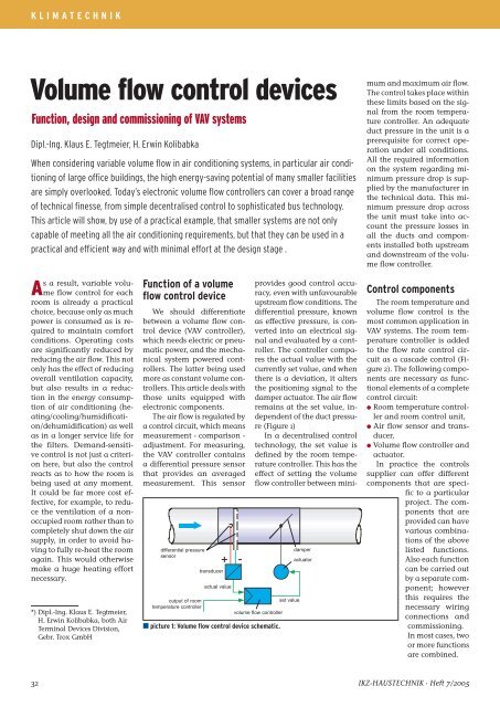
The air <strong>flow</strong> is regulated by<br />
a <strong>control</strong> circuit, which means<br />
measurement - comparison -<br />
adjustment. For measuring,<br />
the VAV <strong>control</strong>ler contains<br />
a differential pressure sensor<br />
that provides an averaged<br />
measurement. This sensor<br />
differential pressure<br />
sensor<br />
output of room<br />
temperature <strong>control</strong>ler<br />
transducer<br />
actual value<br />
+ -<br />
volume <strong>flow</strong> <strong>control</strong>ler<br />
∂ picture 1: <strong>Volume</strong> <strong>flow</strong> <strong>control</strong> device schematic.<br />
set value<br />
damper<br />
actuator<br />
provides good <strong>control</strong> accuracy,<br />
even with unfavourable<br />
upstream <strong>flow</strong> conditions. The<br />
differential pressure, known<br />
as effective pressure, is converted<br />
into an electrical signal<br />
<strong>and</strong> evaluated by a <strong>control</strong>ler.<br />
The <strong>control</strong>ler compares<br />
the actual value with the<br />
currently set value, <strong>and</strong> when<br />
there is a deviation, it alters<br />
the positioning signal to the<br />
damper actuator. The air <strong>flow</strong><br />
remains at the set value, independent<br />
of the duct pressure<br />
(Figure 1)<br />
In a decentralised <strong>control</strong><br />
technology, the set value is<br />
defined by the room temperature<br />
<strong>control</strong>ler. This has the<br />
effect of setting the volume<br />
<strong>flow</strong> <strong>control</strong>ler between minimum<br />
<strong>and</strong> maximum air <strong>flow</strong>.<br />
The <strong>control</strong> takes place within<br />
these limits based on the signal<br />
from the room temperature<br />
<strong>control</strong>ler. An adequate<br />
duct pressure in the unit is a<br />
prerequisite for correct operation<br />
under all conditions.<br />
All the required information<br />
on the system regarding minimum<br />
pressure drop is supplied<br />
by the manufacturer in<br />
the technical data. This minimum<br />
pressure drop across<br />
the unit must take into account<br />
the pressure losses in<br />
all the ducts <strong>and</strong> components<br />
installed both upstream<br />
<strong>and</strong> downstream of the volume<br />
<strong>flow</strong> <strong>control</strong>ler.<br />
Control components<br />
The room temperature <strong>and</strong><br />
volume <strong>flow</strong> <strong>control</strong> is the<br />
most common application in<br />
VAV systems. The room temperature<br />
<strong>control</strong>ler is added<br />
to the <strong>flow</strong> rate <strong>control</strong> circuit<br />
as a cascade <strong>control</strong> (Figure<br />
2). The following components<br />
are necessary as functional<br />
elements of a complete<br />
<strong>control</strong> circuit:<br />
∑ Room temperature <strong>control</strong>ler<br />
<strong>and</strong> room <strong>control</strong> unit,<br />
∑ Air <strong>flow</strong> sensor <strong>and</strong> transducer,<br />
∑ <strong>Volume</strong> <strong>flow</strong> <strong>control</strong>ler <strong>and</strong><br />
actuator.<br />
In practice the <strong>control</strong>s<br />
supplier can offer different<br />
components that are specific<br />
to a particular<br />
project. The components<br />
that are<br />
provided can have<br />
various combinations<br />
of the above<br />
listed functions.<br />
Also each function<br />
can be carried out<br />
by a separate component;<br />
however<br />
this requires the<br />
necessary wiring<br />
connections <strong>and</strong><br />
commissioning.<br />
In most cases, two<br />
or more functions<br />
are combined.<br />
32 IKZ-HAUSTECHNIK · Heft 7 /2005
KLIMATECHNIK<br />
2 3<br />
1 Room temperature <strong>control</strong>ler with temperature sensor <strong>and</strong> set-point adjuster<br />
2 Compact <strong>control</strong>ler, supply air<br />
3 Compact <strong>control</strong>ler, extract air<br />
∂ picture 2: Room temperature <strong>control</strong> with a variable volume <strong>flow</strong> system.<br />
Project <strong>design</strong><br />
The following example (Figure<br />
3) is particularly suitable<br />
for a decentralised <strong>control</strong>,<br />
whereby the combination of<br />
<strong>control</strong> functions specifically<br />
suits the responsibilities of the<br />
air conditioning installer <strong>and</strong><br />
the building <strong>control</strong> contractor<br />
in a good way. Therefore<br />
the room temperature <strong>control</strong>ler<br />
comprises a room module<br />
which contains the <strong>control</strong>ler<br />
as well as the set-point<br />
adjuster <strong>and</strong> the temperature<br />
sensor. This module, more<br />
commonly described as a<br />
room temperature <strong>control</strong>ler,<br />
is mounted in a suitable place<br />
in the room to provide an optimum<br />
temperature measurement.<br />
On the VAV <strong>control</strong>ler,<br />
there is a so called compact<br />
<strong>control</strong>ler that combines the<br />
effective pressure-transducer,<br />
the volume <strong>flow</strong> <strong>control</strong>ler<br />
<strong>and</strong> the actuator into one<br />
casing (Figure 4). The interconnection<br />
of both <strong>control</strong>lers<br />
is carried out by means of a<br />
signal voltage. The electrical<br />
wiring is therefore extremely<br />
simple so that only an additional<br />
24 VAC transformer is<br />
needed to supply voltage to<br />
both <strong>control</strong>lers.<br />
1<br />
In the <strong>design</strong> phase of a<br />
project the required air <strong>flow</strong><br />
rates for individual rooms are<br />
calculated along with the sizing<br />
of <strong>flow</strong> rate <strong>control</strong>lers<br />
<strong>and</strong> most importantly the<br />
overall integration of the entire<br />
system is dealt with.<br />
As a result, nothing is<br />
missed. Here is an overview:<br />
Selection of the units<br />
∑ Construction<br />
∑ Accessories<br />
∑ Control components<br />
Sizing of the <strong>devices</strong><br />
office<br />
TVR 160<br />
V min = 200m 3 /h<br />
V max = 600m 3 /h<br />
CA 160<br />
1,0 m<br />
L pA = 38 d(B)A<br />
CA 250<br />
1,5 m<br />
L pA = 42 d(B)A<br />
∂ picture 4: <strong>Volume</strong> <strong>flow</strong><br />
<strong>control</strong> device TVR-Easy.<br />
room 1 room 2 room 3<br />
CA 200<br />
1,0 m<br />
L pA = 43 d(B)A<br />
L pA = 38 d(B)A L pA = 41 d(B)A L pA = 41 d(B)A L pA = 41 d(B)A<br />
CA 160<br />
1,0 m<br />
TVR 160<br />
V min = 200m 3 /h<br />
V max = 600m 3 /h<br />
TVR 250<br />
V min =500m 3 /h<br />
V max = 1400m 3 /h<br />
CA 250<br />
1,5 m<br />
TVR 250<br />
V min = 465m 3 /h<br />
V max = 1300m 3 /h<br />
TVR 250<br />
V min = 500m 3 /h<br />
V max = 1400m 3 /h<br />
CA 250<br />
1,5 m<br />
L pA = 42 d(B)A<br />
CA 250<br />
1,5 m<br />
TVR 250<br />
V min = 465m 3 /h<br />
V max = 1300m 3 /h<br />
TVR 200<br />
V min =200m 3 /h<br />
V max = 1000m 3 /h<br />
CA 200<br />
1,0 m<br />
TVR 200<br />
V min =180m 3 /h<br />
V max = 900m 3 /h<br />
toilet<br />
toilet<br />
∆p<br />
∆p<br />
∑ Sizes based on the air <strong>flow</strong><br />
∑ Acoustic requirements<br />
Entire system<br />
∑ Calculation of duct system<br />
∑ Installation planning<br />
∑ Electrical planning<br />
Selection of the <strong>devices</strong><br />
As a rule, the specified<br />
acoustic requirements are<br />
the main feature when selecting<br />
the <strong>devices</strong>. When there<br />
is a requirement for low noise<br />
levels normally terminal<br />
units with integral silencing<br />
sections are required. However<br />
for most normal applications<br />
the st<strong>and</strong> alone circular<br />
or rectangular <strong>flow</strong> rate<br />
<strong>control</strong>lers are quite adequa-<br />
RN 160<br />
350 m 3 /h<br />
L pA = 42 d(B)A<br />
CA 160<br />
0,5 m<br />
∂ picture 3: Variable volume <strong>flow</strong> system schematic, e.g. Internet cafe, laboratory.<br />
Heft 7 /2005 · IKZ-HAUSTECHNIK 33
KLIMATECHNIK<br />
∂ picture 5: Installation of vav-system<br />
te. The <strong>control</strong> equipment is<br />
chosen so that a commercial<br />
temperature <strong>control</strong>ler (including<br />
a temperature sensor<br />
<strong>and</strong> a set-point adjuster)<br />
<strong>control</strong>s a compact <strong>control</strong>ler.<br />
The setting of the Vmin <strong>and</strong><br />
Vmax volume <strong>flow</strong>s is carried<br />
out by this compact <strong>control</strong>ler.<br />
Further adjustments are<br />
not necessary.<br />
Sizing of the <strong>devices</strong><br />
In the first instance the<br />
unit size is determined by the<br />
required air <strong>flow</strong> rate. However,<br />
this should also be done<br />
bearing in mind the possible<br />
need to subsequently increase<br />
or decrease the nominal<br />
<strong>flow</strong> rate.<br />
The next step is to determine<br />
the room sound pressure<br />
level for the size of unit selected.<br />
Under certain circumstances,<br />
the selection of the<br />
next size up can give better<br />
results making further noise<br />
<strong>control</strong> measures unnecessary.<br />
Checking the anticipated<br />
noise levels requires reference<br />
to manufacturers published literature.<br />
It is normal to deduct<br />
a figure for room attenuation<br />
in this process. To achieve 45<br />
dB(A) in any room, a circular<br />
<strong>control</strong>ler with a secondary<br />
attenuator is required. Take<br />
care when the resulting noise<br />
levels are close to the specified<br />
overall room level. In this<br />
case a full acoustic analysis is<br />
required to allow for all other<br />
noise sources.<br />
230 VAC<br />
24 VAC<br />
N<br />
Keep <strong>control</strong> components<br />
accessible<br />
Duct system calculation<br />
The total duct system is<br />
usually sized on the basis of<br />
an air velocity of 6 to 8 m/s.<br />
A more detailed duct system<br />
calculation taking into consideration<br />
each of the individual<br />
boxes is normally not<br />
necessary. Finally, the volume<br />
<strong>flow</strong> <strong>control</strong>ler has the regulating<br />
task, independent of<br />
the duct pressure. However,<br />
the largest section of the duct<br />
must be evaluated using the<br />
maximum <strong>flow</strong> rate, so that<br />
the fan can be sized <strong>and</strong> the<br />
set value for the duct pressure<br />
<strong>control</strong>ler can be pre-determined.<br />
The selection of the<br />
measuring location for the<br />
duct pressure <strong>control</strong> is important.<br />
The pressure<br />
sensor is normally<br />
located in<br />
the ducting down<br />
stream of the fan<br />
but before the first<br />
off. Only in this<br />
way can sufficient<br />
system pressure be<br />
guaranteed under<br />
all operating conditions.<br />
Installation<br />
For installation,<br />
the experienced<br />
technician needs<br />
no special instructions.<br />
However, it must<br />
be pointed out here that the<br />
<strong>control</strong> components, in spite<br />
of being maintenance free<br />
<strong>and</strong> having a long life span,<br />
can fail or need to be checked.<br />
For this reason, accessibility<br />
is important <strong>and</strong> necessary.<br />
The <strong>flow</strong> volume <strong>control</strong>lers<br />
therefore must be installed in<br />
such a way that there is adequate<br />
access to the side where<br />
the <strong>control</strong> components are<br />
located (Figure 5). If necessary,<br />
the units can also be rotated,<br />
unless the manufacturer<br />
specifies a particular installation<br />
orientation.<br />
set signal cooling<br />
Electrical planning<br />
Most commercial electronic<br />
volume <strong>flow</strong> <strong>control</strong>lers<br />
need a 24 VAC supply. A decision<br />
has to be made as to<br />
whether to provide a 24V network<br />
or transformers are used<br />
for each room/zone. In our<br />
example (decentralised concept),<br />
the second variant (Figure<br />
6) is recommended.<br />
Commissioning<br />
For commissioning, normally<br />
no adjustment is necessary.<br />
All <strong>control</strong>ler functions<br />
should be checked in<br />
every room. The actual value<br />
<strong>and</strong> the set value of the<br />
compact <strong>control</strong>ler can be examined<br />
<strong>and</strong> checked with an<br />
adjuster. Recently there is also<br />
a <strong>control</strong>ler available with a<br />
<strong>control</strong> light to indicate when<br />
the air <strong>flow</strong> is correct (Figure<br />
4). Should the <strong>flow</strong> rate limits<br />
change after installation, this<br />
is no problem. The new values<br />
are provided using an adjuster<br />
or directly set into the <strong>control</strong>ler.<br />
The volume <strong>flow</strong> <strong>control</strong>lers<br />
are mechanically maintenance-free.<br />
However, the<br />
<strong>control</strong>ler functions should be<br />
checked as part of an annual<br />
maintenance check of the<br />
unit. Here, there is also an opportunity<br />
to assess the room<br />
1 2 YC 1 2 3 4 1 2 3 4<br />
Room temperature<br />
<strong>control</strong>ler<br />
<strong>Volume</strong> <strong>flow</strong><br />
<strong>control</strong>ler supply<br />
air<br />
actual value supply air<br />
<strong>Volume</strong> <strong>flow</strong><br />
<strong>control</strong>ler extract<br />
air<br />
∂ picture 6: Wiring diagram of room temperature <strong>control</strong> with both variable supply <strong>and</strong> extract volume <strong>flow</strong> <strong>control</strong>.<br />
set value<br />
actual value<br />
set value<br />
34 IKZ-HAUSTECHNIK · Heft 7 /2005
KLIMATECHNIK<br />
inquired<br />
The <strong>design</strong> <strong>and</strong> installation of<br />
variable volume <strong>flow</strong> <strong>control</strong>lers<br />
promises a simple option<br />
to achieve the required results.<br />
But even here, it can quickly<br />
lead to errors. The IKZ-HAUS-<br />
TECHNIK editorial office asked<br />
Dipl.-Ing. Klaus E. Tegtmeier<br />
of Gebrüder Trox GmbH what<br />
he thinks.<br />
IKZ-HAUSTECHNIK: In your<br />
expert opinion, where do the<br />
most common errors occur<br />
during the <strong>design</strong> <strong>and</strong> installation<br />
of a volume <strong>flow</strong> <strong>control</strong>ler?<br />
Tegtmeier: From the experience<br />
of our colleagues in the<br />
service team, as well as from<br />
our own site visits to many<br />
completed <strong>and</strong> up <strong>and</strong> running<br />
systems, there are two<br />
quite clear areas of error: the<br />
installation location <strong>and</strong> the<br />
wiring of the unit.<br />
First of all, when considering<br />
the installation location,<br />
care must be taken to ensure<br />
that the device is mounted<br />
in the right place. If the<br />
volume <strong>flow</strong> for each room<br />
is preset on each unit, there<br />
is a risk of errors during<br />
installation. Consequences:<br />
the air <strong>flow</strong> must be reset,<br />
which is possible but causes<br />
additional <strong>and</strong> unnecessary<br />
effort <strong>and</strong> work. However, if<br />
the units are installed with<br />
the wrong air <strong>flow</strong> direction,<br />
the whole unit must be completely<br />
demounted <strong>and</strong> reinstalled<br />
correctly.<br />
Our main issue, to which we<br />
always come back to, is the<br />
accessibility to the <strong>control</strong><br />
components. The <strong>control</strong>ler<br />
must be commissioned <strong>and</strong><br />
also even the best technology<br />
can malfunction. Furthermore,<br />
the need to change the<br />
Klaus E. Tegtmeier<br />
connections can often occur.<br />
However, wiring errors<br />
are often not detected until<br />
the function test for commissioning<br />
is being carried out.<br />
This error must be corrected<br />
by either re-connecting or renewing<br />
the cables.<br />
IKZ-HAUSTECHNIK: How<br />
can these errors be avoided?<br />
Tegtmeier: A lot of errors can<br />
be avoided when the fitters<br />
are comprehensively informed<br />
<strong>and</strong> the activities coordinated.<br />
Often, they are left<br />
to their own <strong>devices</strong> <strong>and</strong> sometimes<br />
have insufficient, or<br />
at worst, no written guidelines<br />
to h<strong>and</strong>.<br />
There can be no place for<br />
mediocre work. However,<br />
we all know it is common<br />
practise. Nevertheless, one<br />
should not yield to this, but<br />
should take into consideration,<br />
as early as possible<br />
in the planning stage, that<br />
the device remains accessible<br />
for servicing. In the building<br />
phase, the building supervision<br />
is required to establish<br />
with the technicians<br />
that this area remains free<br />
<strong>and</strong> accessible.<br />
usage that means, whether<br />
new heat sources or workstations<br />
have been added or removed.<br />
The settings can then<br />
be adjusted accordingly. ∂<br />
Pictures: Gebrüder Trox<br />
GmbH, Neukirchen-Vluyn<br />
@ Further information:<br />
www.trox.de<br />
Heft 7 /2005 · IKZ-HAUSTECHNIK 35