ASHRAE Journal: Designing Chilled Beams for Thermal ... - TROX
ASHRAE Journal: Designing Chilled Beams for Thermal ... - TROX
ASHRAE Journal: Designing Chilled Beams for Thermal ... - TROX

Create successful ePaper yourself
Turn your PDF publications into a flip-book with our unique Google optimized e-Paper software.
The sensible cooling coil within the beam is supplied with<br />
chilled water whose supply temperature is maintained at, or<br />
above, the space dew-point temperature to prevent condensation.<br />
The sensible heat removed by the coil typically constitutes<br />
50% to 75% of the required space sensible heat removal. As a<br />
result, the primary airflow rate required to accomplish the space<br />
sensible cooling can be reduced accordingly.<br />
Although primary (ducted) airflow rates associated with<br />
chilled beams are considerably lower than those in all-air systems,<br />
their discharge airflow rate to the room is always greater.<br />
Since the chilled water supplied to the beam is maintained<br />
above the space dew point, the beam’s off-coil temperature<br />
will be higher than the primary air temperatures used in all-air<br />
systems. The resultant temperature of the beam’s discharge<br />
mixture is typically 3°F to 6°F (2°C to 3.3°C) warmer than<br />
that of all-air systems. There<strong>for</strong>e, a proportionally higher<br />
(20% to 30%) discharge airflow rate to the space must be<br />
provided. This higher discharge flow rate often contributes to<br />
greater draft risks, which may compromise occupant thermal<br />
com<strong>for</strong>t levels.<br />
V L ’ T L<br />
1<br />
Beam A<br />
V O ’ T O<br />
Q S<br />
Q A Q A<br />
2<br />
4<br />
5<br />
3<br />
A<br />
Beam B<br />
V C<br />
V O ’ T O<br />
Q S<br />
H1<br />
V H1 ’ T H1<br />
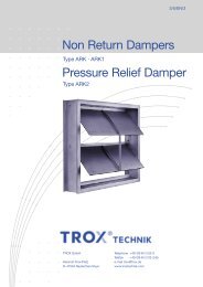
<strong>Designing</strong> <strong>for</strong> Occupant <strong>Thermal</strong> Com<strong>for</strong>t<br />
Standard 55-2004 2 defines the occupied zone as the portion of<br />
a space where occupants normally reside. It is further quantified<br />
as the volume of the room that is (1) no closer than 3.3 ft (1 m)<br />
from any outside walls or windows nor within 1 ft (0.3 m) of<br />
any internal wall and (2) is vertically bounded by the floor and<br />
the head level of the predominant space occupants. Although<br />
the head level is often accepted to be 67 in. (1.7 m) <strong>for</strong> standing<br />
occupants, the standard allows the designer to define that<br />
height according to the space occupancy.<br />
For example, if a space is predominantly occupied by seated<br />
persons, the occupied zone height could be considered as 42 in.<br />
(1.1 m). Chapter 20 of the 2007 <strong>ASHRAE</strong> Handbook— HVAC<br />
Applications 3 predicts the percentage of occupants who might<br />
express thermal dissatisfaction <strong>for</strong> various combinations of<br />
local air speed and temperatures. Figure 2 (from that chapter)<br />
can be used to predict the percentage of occupants that will<br />
object to various air speeds and temperatures at the neck and<br />
ankle regions. As active chilled beams are normally mounted<br />
overhead, the neck region is usually the most critical. Com<strong>for</strong>t<br />
cooling applications should strive to minimize dissatisfaction<br />
levels, and in all cases limit the percentage of occupants objecting<br />
to these local conditions to 20% or less.<br />
Room Air Distribution<br />
Active chilled beams distribute air within the room in a<br />
manner consistent with that of linear slot diffusers. As such,<br />
relationships between airstream terminal velocities and thermal<br />
decay of the supply airstream that apply to linear slot diffusers<br />
also apply to active chilled beams. Upon discharge to the open<br />
space, velocity and temperature differentials between the supply<br />
air mixture and the room begin to diminish due to room air<br />
entrainment. Linear slot diffusers exhibit relatively long throw<br />
characteristics and their velocity and temperature differentials<br />
1 m<br />
(0.3 ft)<br />
Occupied Zone<br />
(Height Determined By Designer)<br />
Figure 1: Application of active chilled beams.<br />
diminish at a rate that is proportional to the distance the air has<br />
traveled within the space.<br />
Manufacturers publish throw values that allow designers to<br />
estimate the travel distance of the airstream be<strong>for</strong>e it reaches a<br />
given terminal velocity. Most manufacturers present such data<br />
using isothermal air <strong>for</strong> terminal velocities of 150, 100 and 50<br />
fpm (0.75, 0.5 and 0.25 m/s). These data can be used to map<br />
the airstream and predict the local velocity at the point where it<br />
enters the occupied zone. As the room-to-supply-air-differential<br />
decays at a similar rate, its temperature also can be predicted<br />
at the entry point based on the initial temperature difference<br />
(ΔT O ) between the beam discharge temperature and that of the<br />
room into which it is introduced. Manufacturers supply selection<br />
software that can be used predict the value of local velocities<br />
and temperatures at critical locations such as that where the<br />
airstream enters the occupied zone.<br />
Figure 1 illustrates a space being served by two active beams<br />
with two-way discharge patterns delivering identical primary<br />
(Q P ) and discharge (Q S ) airflow rates. The discharge airflow<br />
rate is a function of the induction ratio of the nozzles chosen<br />
and is calculated by multiplying the primary airflow rate by the<br />
induction ratio. Assume a beam produces an induction ratio of<br />
2.5 and is sized to deliver 100 cfm (170 m 3 /h) of 55°F (13°C)<br />
primary air to a 75°F (24°C) room. Also, assume that chilled<br />
water enters the beam at 57°F (14°C) and leaves at 61°F (16°C).<br />
The discharge airflow rate to the space will be 3.5 times the<br />
O c t o b e r 2 0 0 9 A S H R A E J o u r n a l 5 9