

Performance of Notched Coach Screw Connection for Timber ...
Performance of Notched Coach Screw Connection for Timber ...
Performance of Notched Coach Screw Connection for Timber ...

Create successful ePaper yourself
Turn your PDF publications into a flip-book with our unique Google optimized e-Paper software.
<strong>Per<strong>for</strong>mance</strong> <strong>of</strong> <strong>Notched</strong> <strong>Coach</strong> <strong>Screw</strong> <strong>Connection</strong> <strong>for</strong> <strong>Timber</strong>-Concrete<br />
Composite Floor System ∗<br />
David Yeoh Eng Chuan 1 , Massimo Fragiacomo 2 , Pietro Aldi 3 , Marta Mazzilli 1 , Ulrike Kuhlmann 3<br />
1 University <strong>of</strong> Canterbury, Christchurch, New Zealand<br />
2 Associate Pr<strong>of</strong>essor <strong>of</strong> Structural Design, University <strong>of</strong> Sassari, Alghero, Italy<br />
3 Institute <strong>of</strong> Structural Design/University <strong>of</strong> Stuttgart, Germany<br />
Abstract<br />
The notched connection <strong>for</strong> timber-concrete composite beams is obtained by cutting a notch from the timber beam and<br />
filling it with concrete during the pouring <strong>of</strong> the concrete slab. This type <strong>of</strong> connection has the advantage <strong>of</strong> high stiffness<br />
and strength compared to mechanical fasteners. The paper presents the outcomes <strong>of</strong> a parametric study <strong>of</strong> fourteen<br />
variations <strong>of</strong> notched connections which were loaded to failure under shear in push-out specimens. Laminated veneer<br />
lumber (LVL) was used <strong>for</strong> the timber part. Stiffness and strength values obtained from the different connection<br />
variations were compared to each other in order to identify the best types. Rectangular and triangular notches rein<strong>for</strong>ced<br />
with a coach screw were found to per<strong>for</strong>m satisfactorily. An alternative connection system with punched metal plates was<br />
also found to per<strong>for</strong>m well, with the additional benefit <strong>of</strong> ease <strong>of</strong> construction. The experimental results were compared<br />
with numerical results carried out using a 3D finite element model implemented in ANSYS s<strong>of</strong>tware package. Agreement<br />
was found between the predicted and the experimental failure mechanisms, however further work is needed to fully<br />
calibrate the s<strong>of</strong>tware on the experimental results.<br />
1. Introduction<br />
The timber concrete composite (TCC) floor system is a construction technique where a concrete slab is mechanically<br />
connected to its supporting timber joists using either notches cut from the timber or mechanical fasteners. The concrete<br />
can be cast in-situ or alternatively the fasteners can be inserted into a prefabricated concrete slab to provide on-site<br />
connection to the timber. The shear connectors provide composite action which utilizes the advantages <strong>of</strong> both<br />
materials: tensile and bending resistance <strong>of</strong> timber, and compressive strength <strong>of</strong> concrete [1]. The per<strong>for</strong>mance <strong>of</strong> the<br />
TCC beam is significantly influenced by the behaviour <strong>of</strong> the connection system. Stiff and strong shear connectors are<br />
required to provide optimal structural efficiency. Some ductility is desirable since both timber and concrete exhibit quite<br />
brittle behaviour in tension and compression respectively, and the plasticization <strong>of</strong> the connection is the only source <strong>of</strong><br />
ductility <strong>for</strong> the TCC system [2-3]. However, the connection system needs to be inexpensive to manufacture and install<br />
to make TCC floors competitive with other construction systems such as steel and precast concrete.<br />
Cast in-situ concrete<br />
65 mm thick<br />
with rein<strong>for</strong>cement<br />
D10-200 c/c both ways<br />
Double LVL 400x63<br />
Plywood interlayer<br />
17 mm thick<br />
<strong>Notched</strong> coach screw connection<br />
Ø16 mm diameter<br />
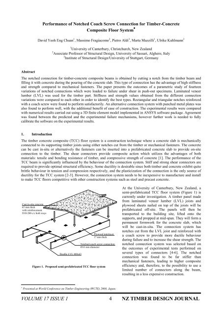
Figure 1. Proposed semi-prefabricated TCC floor system<br />
At the University <strong>of</strong> Canterbury, New Zealand, a<br />
semi-prefabricated TCC floor system (Figure 1) is<br />
currently under investigation. A timber panel made<br />
from laminated veneer lumber (LVL) joists and<br />
plywood sheets nailed on top <strong>of</strong> the joists will be<br />
prefabricated <strong>of</strong>f-site. The panels will then be<br />
transported to the building site, lifted onto the<br />
supports, and propped at mid-span. They will <strong>for</strong>m a<br />
permanent <strong>for</strong>mwork <strong>for</strong> the concrete slab, which<br />
will be cast-in-situ. The connection system has<br />
notches cut from the LVL joist and rein<strong>for</strong>ced with<br />
a coach screw to provide more ductile behaviour<br />
during failure and to increase the shear strength. The<br />
notched connection system was selected based on<br />
the outcomes <strong>of</strong> experimental tests per<strong>for</strong>med on<br />
several types <strong>of</strong> connectors [4-6]. The notched<br />
connection was found to be far stiffer than<br />
mechanical fasteners, leading to higher composite<br />
efficiency and, there<strong>for</strong>e, to the possibility to use a<br />
limited number <strong>of</strong> connectors along the beam,<br />
resulting in a less expensive construction.<br />
∗ Presented at World Conference on <strong>Timber</strong> Engineering (WCTE) 2008, Japan.<br />
VOLUME 17 ISSUE 1 4 NZ TIMBER DESIGN JOURNAL
This paper reports the results <strong>of</strong> experimental tests recently per<strong>for</strong>med on different notched connection systems. The<br />
purpose was to identify the parameters affecting the mechanical properties (shear stiffness and strength) and to<br />
ultimately optimize the connection detail. Geometrical variations included shape <strong>of</strong> the notch (rectangular, triangular<br />
and dove-tail), depth and length <strong>of</strong> the notch, use or not <strong>of</strong> a coach screw, diameter <strong>of</strong> the coach screw and the<br />
embedment length into the timber. In addition, toothed metal plate connections were also tested since this system is<br />
considerably easier to construct. The behaviour <strong>of</strong> all connections was characterized in terms <strong>of</strong> shear strength and<br />
stiffness at strength and serviceability limit state by testing small timber-concrete composite blocks with the connection<br />
loaded in shear (push-out specimens) to failure. Simplified analytical <strong>for</strong>mulae based on the New Zealand Standard <strong>for</strong><br />
the design <strong>of</strong> the notch under all possible failure mechanisms, were developed and compared with the experimental<br />
results. A 3D finite element model <strong>of</strong> the connection detail was implemented into the ANSYS [10] s<strong>of</strong>tware package<br />
and compared with the experimental results.<br />
2. <strong>Connection</strong> Push-Out Test<br />
An experimental parametric study is<br />
essential <strong>for</strong> the optimization <strong>of</strong> the<br />
notch shape so that the best<br />
compromise between labour cost<br />
and structural efficiency is achieved.<br />
The per<strong>for</strong>mance <strong>of</strong> different<br />
connector shapes listed in Table 1<br />
was evaluated through experimental<br />
push-out shear tests per<strong>for</strong>med on<br />
small LVL-concrete composite<br />
blocks (Figure 2). Variations <strong>of</strong> the<br />
typical notched connection (Figure<br />
3a) included the length, depth, and<br />
shape (dovetail, triangular and<br />
rectangular) <strong>of</strong> the notch. <strong>Coach</strong><br />
screws <strong>of</strong> 12 mm and 16 mm<br />
diameters were also inserted in the<br />
centre <strong>of</strong> the notches in some cases,<br />
while in other cases no coach screw<br />
Figure 2. Symmetrical push-out test setup (dimensions in mm)<br />
was used. The depth <strong>of</strong> penetration<br />
<strong>of</strong> the coach screw into the LVL,<br />
and the end distance <strong>of</strong> the notch from the LVL were also varied. Slightly modified toothed metal plate fasteners<br />
(Figure 3b) that were pressed in the lateral side <strong>of</strong> two adjacent 400 × 63 mm LVL joists were also investigated and<br />
compared with the notched connections. A total <strong>of</strong> 15 different types <strong>of</strong> connection were selected. Two push-out<br />
specimens were then constructed <strong>for</strong> each connection type, <strong>for</strong> a total <strong>of</strong> 30 specimens. The push-out tests were<br />
per<strong>for</strong>med in accordance with EN 26891 [7] where the connections are loaded in shear and the load-slip relationship<br />
recorded using a load cell and potentiometers P1, P2, P5 and P6 (Figure 2).<br />
100<br />
Concrete slab<br />
Plywood<br />
650<br />
65<br />
21<br />
180<br />
70<br />
180 70<br />
Double side<br />
tooth metal plate<br />
2mm thick<br />
Double LVL<br />
63 63<br />
Figure 3. Typical notched coach screw and toothed metal plate connections (dimensions in mm)<br />
VOLUME 17 ISSUE 1 5 NZ TIMBER DESIGN JOURNAL
2.1 Results and Discussion<br />
The relationship between shear <strong>for</strong>ce and relative slip is presented in Figure 4 <strong>for</strong> the 15 specimens most representative<br />
<strong>of</strong> the different connector shapes. The results in terms <strong>of</strong> shear strength (F max ), secant stiffness (also defined as slip<br />
modulus) at 40% (K S,0.4 ), 60% (K S,0.6 ) and 80% (K S,0.8 ) <strong>of</strong> the strength [7] are summarized in Table 1. The strength F max<br />
is defined as the largest value <strong>of</strong> shear <strong>for</strong>ce monitored during the test <strong>for</strong> slips not larger than 15 mm [7]. In order to<br />
provide some in<strong>for</strong>mation on the post-peak behaviour and, there<strong>for</strong>e, on the ductility level, the ratio ∆2/∆1 between the<br />
difference in strength at peak and at 10 mm slip, ∆2, and the peak strength, ∆1, is reported in Table 1. The lower the<br />
∆2/∆1 ratio, the better the post-peak behaviour and the higher the ductility.<br />
Shear Force versus Relative Slip <strong>for</strong> all Specimens<br />
350<br />
A1-Rect150x50NCS16<br />
Shear Force (kN)<br />
300<br />
250<br />
200<br />
150<br />
C2<br />
E2<br />
H1<br />
A3<br />
A1<br />
H3<br />
F1<br />
C1<br />
H2<br />
G1<br />
shear in<br />
concrete<br />
length<br />
A2-Rect50x50NCS16<br />
A3-Rect150x25NCS16<br />
B1-Rect150x50Notch<br />
C1-Rect150x50NCS12<br />
C2-Rect150x50NCS16deep<br />
D1-DoveTail 150 Notch<br />
E1-Tri30_60Notch<br />
E2-Tri30_60NCS16<br />
F1-Rect150x50NCS16short<br />
G1-Rect150x50NCS16LSConc<br />
H1-Rect150x50NCS16double<br />
100<br />
H2-MPC650length<br />
H3-MPC325length<br />
H4-MPC150length<br />
50<br />
0<br />
D1<br />
B1<br />
A2<br />
E1<br />
H4<br />
0 5 10 15 20 25<br />
Relative Slip (mm)<br />
Figure 4. Relationship between shear <strong>for</strong>ce and relative slip <strong>for</strong> 15 tested connection systems with photo <strong>of</strong> the shear failure in notched<br />
connection with coach screw<br />
The most important factors affecting the connection per<strong>for</strong>mance were found to be the length <strong>of</strong> the notch (compare<br />
F max <strong>for</strong> specimens A1, 73kN and A2, 46kN) and the presence <strong>of</strong> a coach screw (compare F max <strong>for</strong> specimens<br />
A1,=73kN, and B1, 48.3kN). Generally, all <strong>of</strong> the specimens failed by shear in the concrete (photo in Figure 4), hence a<br />
longer length <strong>of</strong> notch is necessary to improve the shear strength. The only source <strong>of</strong> ductility was provided by the<br />
coach screw, which also significantly increased the resistance. The presence <strong>of</strong> a coach screw and its depth <strong>of</strong><br />
penetration into the timber (compare K s,0.4 <strong>for</strong> specimens A1 with 100mm penetration,, 80kN/mm, and C2 with 140mm<br />
penetration, 211kN/mm,) significantly enhanced the stiffness <strong>of</strong> the connection.<br />
The triangular shaped notch demonstrated close if not equal per<strong>for</strong>mance to that <strong>of</strong> a rectangular notch (compare F max<br />
<strong>for</strong> specimens A1, 73kN, and E2, 83kN), thus making it one <strong>of</strong> the more viable options as it is much easier to<br />
manufacture. The metal plate connection (specimens H2, H3 and H4) exhibited a ductile plate tearing failure with high<br />
strength and stiffness. In addition, the strength <strong>of</strong> the latter connection can be easily determined from the plate’s yield<br />
strength and length.<br />
Based on the outcomes <strong>of</strong> these experimental tests to failure, and taking into account the ease <strong>of</strong> construction, the four<br />
most promising connection systems were selected: (1) 150 × 25 mm rectangular notch rein<strong>for</strong>ced with 16 mm diameter<br />
coach screw; (2) 300 × 50 mm rectangular notch rein<strong>for</strong>ced with 16 mm diameter coach screw; (3) 150 mm long<br />
triangular notch rein<strong>for</strong>ced with 16 mm diameter coach screw; and (4) toothed metal plate connector. The 300 mm<br />
VOLUME 17 ISSUE 1 6 NZ TIMBER DESIGN JOURNAL
length <strong>of</strong> connection (2) was based on the length <strong>of</strong> notch being an important parameter in obtaining a strong<br />
connection. These systems are being used in the next phases <strong>of</strong> the experimental programme, the dynamic (vibrations)<br />
and static (collapse) test on full-scale strips <strong>of</strong> composite floor.<br />
Table 1. Shear strength and stiffness values <strong>for</strong> 15 different connection systems<br />
<strong>Connection</strong> Type<br />
F max (kN) K s,0.4 K s,0.6 K s,0.8 ∆2/∆1<br />
length × depth × width (mm)<br />
Exp. Anal. (kN/mm) (kN/mm) (kN/mm) (%)<br />
A1: Rectangular notch 150×50×63<br />
<strong>Coach</strong> <strong>Screw</strong> φ16 73.0 68.5 80.2 75.4 61.7 35.5<br />
A2: Rectangular notch 50×50×63<br />
<strong>Coach</strong> <strong>Screw</strong> φ16 46.0 49.1 38.2 34.5 27.5 13.3<br />
A3: Rectangular notch 150×25×63<br />
<strong>Coach</strong> <strong>Screw</strong> φ16 71.8 112.8 102.2 76.1 26.1<br />
B1: Rectangular notch 150×50×63 48.3 56.7 104.7 59.3 41.3 73.9<br />
C1: Rectangular notch 150×50×63<br />
<strong>Coach</strong> <strong>Screw</strong> φ12 66.0 66.3 77.9 74.5 62.3 38.8<br />
C2: Rectangular notch 150×50×63<br />
<strong>Coach</strong> <strong>Screw</strong> φ16 depth 140mm 84.2 87.8 211.2 145.0 95.5 36.5<br />
D1: Doves tail notch 150×50×63 20.5 51.1 28.1 33.5 37.0<br />
E1: Triangular notch 30°_60°<br />
137×60×63 40.2 100.8 57.3 37.9 34.1<br />
E2: Triangular notch 30°_60°<br />
137×60×63 <strong>Coach</strong> <strong>Screw</strong> φ16 82.6 122.8 104.0 75.4 36.5<br />
F1: Rectangular notch short end<br />
150×50×63 <strong>Coach</strong> <strong>Screw</strong> φ16 74.4 92.7 91.1 73.6 49.0<br />
G1: Rectangular notch LSC 150×50×63<br />
<strong>Coach</strong> <strong>Screw</strong> φ16 68.8 67.0 66.9 56.1 49.3<br />
H1: Rectangular notch double LVL<br />
150×50×126 <strong>Coach</strong> <strong>Screw</strong> φ16 128.2 217.9 183.1 119.1 42.1<br />
H2: Double sided toothed metal plate<br />
650 mm 163.9 163.4 377.6 275.9 127.4 44.0<br />
H3: Double sided toothed metal plate<br />
325 mm 81.1 81.7 480.0 508.4 53.4 33.3<br />
H4: Double sided toothed metal plate<br />
150 mm 47.9 37.7 54.3 38.7 31.2 37.5<br />
3. Simplified Analytical Model <strong>for</strong> Strength Evaluation<br />
A simplified analytical model <strong>for</strong> strength evaluation <strong>of</strong> the notched connection is presented in Equations (1) to (4). The<br />
<strong>for</strong>mulae were verified with the experimental results and were found to predict the failure load within acceptable range<br />
in most cases (Table 1).<br />
The model is based on the control <strong>of</strong> all possible failure mechanisms that may occur in the connection region. The<br />
notched connection is regarded as a concrete corbel protruding into the LVL joist subjected to shear and bending<br />
moment coming from the shear load applied on the connection. The coach screw acts as rein<strong>for</strong>cement <strong>for</strong> the concrete<br />
corbel, and contributes to the shear transfer from the timber to the concrete. Figure 5 illustrates the failure mechanism<br />
experimentally observed during most <strong>of</strong> the tests. In general, a shear plane began to <strong>for</strong>m at 0.6F max . Thereafter, the<br />
coach screw started to act in tension until two plastic hinges were developed. At that stage, the coach screw transferred<br />
most <strong>of</strong> the shear <strong>of</strong> the connection by rope effect.<br />
The design <strong>for</strong>mulas are used to calculate the failure load associated with all <strong>of</strong> the possible failure mechanisms <strong>of</strong> the<br />
connection, which are: (1) failure <strong>of</strong> concrete in shear in the notch; (2) failure <strong>of</strong> concrete in compression in the notch;<br />
(3) failure <strong>of</strong> LVL in longitudinal shear, between two consecutive notches or between the last notch and the end <strong>of</strong> the<br />
beam; and (4) failure <strong>of</strong> LVL in crushing parallel to the grain at the interface with the concrete corbel.<br />
VOLUME 17 ISSUE 1 7 NZ TIMBER DESIGN JOURNAL
Concrete<br />
Plywood<br />
Force direction<br />
Shear plane <strong>of</strong> concrete<br />
along length <strong>of</strong> notch<br />
Concrete<br />
Plywood<br />
Force direction<br />
Shear along length <strong>of</strong> notch<br />
begin to <strong>for</strong>m 0.6Fmax<br />
LVL<br />
Concrete<br />
crushing<br />
zone<br />
LVL<br />
1 2<br />
Appearance <strong>of</strong><br />
concrete crushing<br />
<strong>Coach</strong> screw in tension<br />
starts to provide restrain<br />
in the connection<br />
Concrete<br />
Plywood<br />
Force direction<br />
Concrete sheared <strong>of</strong>f at<br />
Fmax along notch length<br />
FORCE<br />
LVL<br />
3<br />
Concrete<br />
crushed<br />
<strong>Coach</strong> screw yielded in<br />
flexure <strong>for</strong>ming plastic<br />
hinges thus provide a<br />
ductile failure<br />
<strong>Coach</strong><br />
<strong>Screw</strong> in<br />
tension<br />
The <strong>for</strong>mulas are reported in the following:<br />
Figure 5. Experimental failure mechanism <strong>of</strong> notched connection with coach screw<br />
1) Nominal shear strength <strong>of</strong> concrete <strong>for</strong> a notched connection rein<strong>for</strong>ced with a coach screw:<br />
F conc,shear = 0.2f' c bd + nkpQ k (1)<br />
where f' c is the compressive strength <strong>of</strong> concrete, b and d are the breadth and depth <strong>of</strong> notch respectively, n is the<br />
number <strong>of</strong> coach screws, k is the modification factor <strong>for</strong> duration <strong>of</strong> loading <strong>for</strong> the timber, p is the depth <strong>of</strong> penetration<br />
and Q k is the characteristic withdrawal strength <strong>of</strong> the coach screw.<br />
2) Nominal compressive strength <strong>of</strong> concrete in the crushing zone:<br />
F conc,crush = f' c A c (2)<br />
where A c is the crushing zone effective area, i.e. b × d.<br />
3) Nominal longitudinal shear strength <strong>of</strong> LVL between two consecutive notches or between the last notch and the end<br />
<strong>of</strong> the timber beam:<br />
F LVL,shear = k 1 k 4 k 5 f s Lb (3)<br />
where k 1 is the modification factor <strong>for</strong> duration <strong>of</strong> load, k 4 and k 5 are the modification factors <strong>for</strong> load sharing , f s is the<br />
LVL characteristic shear stress, L is the shear effective length and b is the breadth <strong>of</strong> the LVL beam.<br />
4) Compressive strength <strong>of</strong> LVL at crushing zone,<br />
F LVL,crush = k 1 f c hb (4)<br />
where f c is the LVL characteristic compressive stress, and h is the depth <strong>of</strong> the notch.<br />
The design value <strong>of</strong> the shear strength is then obtained by multiplying the minimum <strong>of</strong> the four values reported above<br />
by the strength reduction factor φ.<br />
4. Numerical Modelling <strong>of</strong> <strong>Notched</strong> <strong>Connection</strong>s<br />
A numerical analysis <strong>of</strong> the connection type A1 (Table 1) was carried out using the finite element program ANSYS<br />
[10]. The planes <strong>of</strong> symmetry <strong>of</strong> the push-out specimen were used in order to reduce the number <strong>of</strong> degrees <strong>of</strong> freedom:<br />
only a quarter <strong>of</strong> the real geometry was modelled. The solid model and the mesh are represented in Figure 6. A three-<br />
VOLUME 17 ISSUE 1 8 NZ TIMBER DESIGN JOURNAL
dimensional eight-node element with quadratic shape functions was selected to model the solid parts <strong>of</strong> the specimen<br />
(concrete, timber, and coach screw).<br />
Non-linear material models with<br />
different strength values in<br />
tension and compression were<br />
steel plate<br />
used <strong>for</strong> concrete and timber.<br />
The anisotropic behaviour <strong>of</strong><br />
concrete<br />
LVL<br />
timber was also included. The<br />
available “Aniso” material<br />
model, based on the generalised<br />
screw<br />
Hill potential theory [11], was<br />
chosen to simulate the timber<br />
behaviour. The “concrete”<br />
plywood<br />
material option was used to<br />
model the concrete part <strong>of</strong> the<br />
model. The steel <strong>of</strong> the coach<br />
(a) (b)<br />
(c)<br />
screw was modelled with a Figure 6. Implemented geometry(a-b) and utilized mesh (c) <strong>for</strong> the numerical simulation<br />
bilinear material law with<br />
kinematic hardening. For the interface between the concrete and the LVL and <strong>for</strong> the screw/concrete and<br />
timber/concrete surfaces, 3D contact elements were used to simulate the friction among these materials.<br />
A non-linear numerical analysis was carried out by increasing the displacement to failure on the steel plate on the top <strong>of</strong><br />
the specimen. The progressive development <strong>of</strong> a crack path in the concrete <strong>for</strong> different load steps, together with the<br />
contour <strong>of</strong> the principal de<strong>for</strong>mations is illustrated in Figure 7. By comparing Figure 7(d–e) with Figure 5, general<br />
agreement between the predicted and the actual failure mechanism can be noted. A visualisation <strong>of</strong> the principal<br />
concrete de<strong>for</strong>mations in the notch is demonstrated in Figure 7(e) which is found to be compatible with the<br />
experimental failure.<br />
First crack in<br />
notch at 7.74kN<br />
First crack outside<br />
concrete slab at 37.76kN<br />
shear in concrete length<br />
(a) (b) (c) (d)<br />
(e)<br />
Figure 7. Crack growth at different load values (a-d) and contour <strong>of</strong> principal de<strong>for</strong>mations in the concrete part <strong>of</strong> the model (e).<br />
Insert photo shows the experimental comparison.<br />
The development <strong>of</strong> the numerical<br />
model was not completed at the time<br />
this paper was written due to the<br />
difference between predicted and<br />
experimental stiffness: the numerical<br />
value <strong>of</strong> 96.6 kN/mm represents<br />
about 120 % <strong>of</strong> the experimental<br />
secant value at 40% <strong>of</strong> the shear<br />
strength. Figure 8 displays the<br />
experimental and numerical loadslip<br />
comparisons where the<br />
numerical relationship began to<br />
diverge from the experimental<br />
above the 30 kN load step. The<br />
numerical analysis could be run up<br />
to a load <strong>of</strong> 44.07 kN, when<br />
convergence problems occurred.<br />
Such a value is lower than the<br />
experimental one (73 kN).<br />
Load [kN]<br />
(a)<br />
160<br />
140<br />
120<br />
100<br />
80<br />
60<br />
40<br />
20<br />
0<br />
FEM<br />
Exp<br />
0 10 20<br />
Slip [mm]<br />
Load [kN]<br />
160<br />
140<br />
120<br />
100<br />
80<br />
60<br />
40<br />
20<br />
0<br />
experimental data<br />
FEM<br />
0 0.25 0.5 0.75 1 1.25 1.5 1.75 2 2.25<br />
Slip [mm]<br />
Figure 8. Experimental and numerical load-slip comparison<br />
(b)<br />
VOLUME 17 ISSUE 1 9 NZ TIMBER DESIGN JOURNAL
Possible reasons <strong>for</strong> the convergence problems could be inadequate mesh or the utilised material models. Some<br />
refinement and further investigation is needed <strong>for</strong> the calibration <strong>of</strong> the 3D model on the experimental results.<br />
5. Conclusion<br />
Based on the results <strong>of</strong> the shear push-out tests per<strong>for</strong>med on several connection systems, it can be concluded that<br />
rectangular and triangular notches cut from the timber beam and rein<strong>for</strong>ced with coach screws are an excellent<br />
connection system. High shear strength and stiffness can be achieved, along with acceptable post-peak behaviour<br />
characterized by gradual decrease in strength. The most important factors affecting the connection per<strong>for</strong>mance were<br />
found to be the length <strong>of</strong> the notch and the presence <strong>of</strong> a coach screw. Another promising system is the use <strong>of</strong> toothed<br />
metal plates pressed into the lateral surface <strong>of</strong> the LVL joists. This system avoids cutting the timber joist, providing a<br />
simpler and more cost effective construction detail with excellent mechanical per<strong>for</strong>mance.<br />
Design <strong>for</strong>mulae <strong>for</strong> the shear strength <strong>of</strong> the notched connection were derived, based on the control <strong>of</strong> all possible<br />
failure mechanisms. Those <strong>for</strong>mulae were found to predict the experimental failure load within an acceptable range in<br />
most cases. Lastly, the experimental results were compared with numerical results obtained using a 3D finite element<br />
model implemented in the ANSYS s<strong>of</strong>tware package. Predicted and experimental failure mechanisms agreed<br />
reasonably well, although some refinement and further investigation are needed to fully calibrate the model with the<br />
experimental results in terms <strong>of</strong> both strength and stiffness.<br />
6. Acknowledgements<br />
The technical support from Carter Holt Harvey (Mr. Warwick Banks and Mr. Hank Bier), and MiTek NZ (Mr. Steve<br />
Coll and Mr. Antony Cook) is gratefully acknowledged, together with the financial contribution provided by Carter<br />
Holt Harvey and by the New Zealand government through the FIDA funds. Thanks to Dr. James Mackechnie <strong>for</strong> his<br />
advice and help with the preparation <strong>of</strong> the concrete. Special thanks are also due to <strong>for</strong>mer undergraduate student Mr.<br />
James O’Neill <strong>for</strong> his hard work and dedication to this massive research project.<br />
7. References<br />
[1] Ceccotti, A. “<strong>Timber</strong>-concrete composite structures.” <strong>Timber</strong> Engineering STEP 2. 1 st Edition Centrum Hout.<br />
The Netherlands. 1995; pp. E13/1-12.<br />
[2] Frangi, A., and Fontana, M. “Elasto-plastic model <strong>for</strong> timber concrete composite beams with ductile connection.”<br />
IABSE Structural Engineering International. 13(1), 2003; pp. 47-57.<br />
[3] Ceccotti, A., Fragiacomo, M. & Giordano, S. “Long-term and collapse tests on a timber-concrete composite<br />
beam with glued-in connection.” Materials and Structures, RILEM, Special Volume “Research <strong>for</strong> Reliable<br />
<strong>Timber</strong> Structures”, 40(1), 2006; pp. 15-25.<br />
[4] Seibold, E. “Feasibility study <strong>for</strong> composite concrete-timber floor systems using laminated veneer lumber in<br />
NZ.” Dissertation Thesis. University <strong>of</strong> Karlsruhe, Germany. 2004.<br />
[5] Fragiacomo, M., and Deam, B. “Composite concrete slab and LVL flooring systems.” Proceedings <strong>of</strong> the 19 th<br />
Australasian Conference on the Mechanics <strong>of</strong> Structures and Materials. Christchurch, New Zealand. 2006; pp.<br />
57-62.<br />
[6] Deam, B.L., Fragiacomo, M., & Buchanan, A.H. “<strong>Connection</strong>s <strong>for</strong> composite concrete slab and LVL flooring<br />
systems.” Published online, Materials and Structures, RILEM. 2007.<br />
[7] CEN Comite European de Normalisation. “<strong>Timber</strong> structures – Joints made with mechanical fasteners – General<br />
principles <strong>for</strong> the determination <strong>of</strong> strength and de<strong>for</strong>mation characteristics.” EN 26891. Brussels, Belgium.<br />
1991.<br />
[8] NZS 3603. New Zealand Standard <strong>for</strong> <strong>Timber</strong> Structures. 1993.<br />
[9] NZS 3101. New Zealand Standard <strong>for</strong> Concrete Structures, Part 1. 2006.<br />
[10] ANSYS, Release 11.0 – ANSYS Inc. Canonsburg PA 15317 U.S.A.<br />
[11] Shih, C.F. and Lee, D. “Further developments in anisotropic plasticity” Journal <strong>of</strong> Engineering Materials and<br />
Technology. July 1978.<br />
Editors’ note: k4 and k5 are 1.0 <strong>for</strong> properties <strong>of</strong> material with low variability like LVL unless specifically determined<br />
from test data. NZS 3603 factors are <strong>for</strong> higher variability sawn timber should it be used instead <strong>of</strong> LVL.<br />
VOLUME 17 ISSUE 1 10 NZ TIMBER DESIGN JOURNAL


