User Guide - Performance Audio
User Guide - Performance Audio
User Guide - Performance Audio

You also want an ePaper? Increase the reach of your titles
YUMPU automatically turns print PDFs into web optimized ePapers that Google loves.
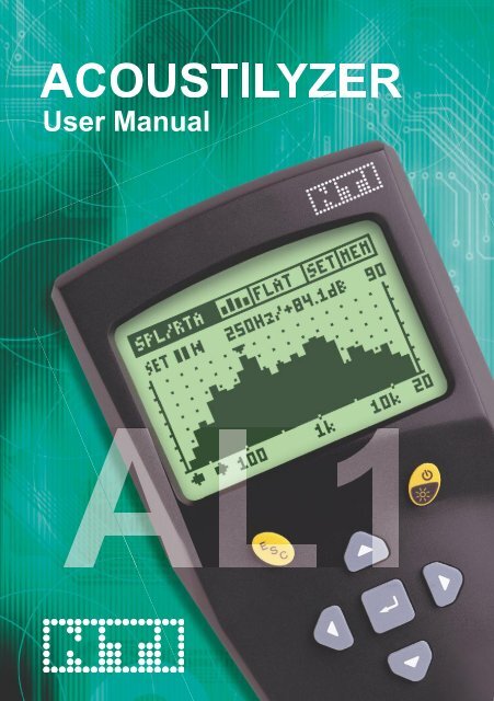
ACOUSTILYZER<br />
<strong>User</strong> Manual<br />
AL1
NTI contact details:<br />
NTI AG<br />
Im alten Riet 102<br />
9494 Schaan<br />
Liechtenstein, Europe<br />
Tel. +423 - 239 6060<br />
Fax +423 - 239 6089<br />
E-mail info@nti-audio.com<br />
Web www.nti-audio.com<br />
© NTI AG<br />
All rights reserved.<br />
Subject to change without notice.<br />
Release 1.31.5e /Apr 2009 / Firmware A1.31 or higher<br />
MiniLINK, Minilyzer, Digilyzer, Acoustilyzer, Minirator, MiniSPL and<br />
Minstruments are trademarks of NTI.<br />
2
Index:<br />
1. Introduction 4<br />
CE Declaration of Conformity 5<br />
International Warranty and Repair 6<br />
Warnings 7<br />
Test & Calibration Certificate 7<br />
2. Overview 8<br />
Acoustilyzer Functions 9<br />
Easy Operation 9<br />
Connectors 10<br />
3. Basic Operation 12<br />
Start-up Screen 13<br />
Menu Bar 13<br />
4. Measurement Functions 22<br />
SPL/RTA - Sound Level Meter 23<br />
SPL/RTA - Real Time Analyzer RTA 27<br />
Reverberation Time RT60 36<br />
FFT Analysis 42<br />
Polarity Test 46<br />
Delay Time 48<br />
Electrical Measurements - RMS/THD 51<br />
Speech Intelligibility STI-PA (optional) 53<br />
Calibration 61<br />
5. MiniLINK PC Software 64<br />
Installation 64<br />
Start the MiniLINK PC Software 65<br />
Free Registration of your Test Instrument 66<br />
Read Out of Stored Test Results 67<br />
Visualizing the Test Results 68<br />
Test Result Logging at the PC 72<br />
Remote Test Instrument Control with the PC 74<br />
MiniLINK Tools 75<br />
Activate Options 81<br />
6. Troubleshooting 82<br />
7. Accessories 83<br />
8. Technical Specification 85<br />
9. Appendix: Introduction to STI-PA 88<br />
3
1. Introduction<br />
Congratulations and thank you for buying NTI’s Acoustilyzer AL1, a<br />
product specially suited for professional acoustical test applications. The<br />
Acoustilyzer offers advanced acoustics functions including an optional<br />
speech intelligibility STI-PA measurement module and further basic<br />
electrical features. We are convinced you will enjoy using it!<br />
This manual describes the Acoustilyzer AL1 functions and measurements<br />
in detail. Further application information about the acoustical and electrical<br />
measurements can be found on the web site “www.nti-audio.com”.<br />
The Acoustilyzer AL1 is available as stand alone test instrument or as<br />
crossgrade package for existing Minilyzer ML1 users. The same crossgrade<br />
option can be used to install the Minilyzer functionalities on the AL1. The<br />
STI-PA measurement feature is optional.<br />
The product packages include the following items:<br />
Acoustilyzer AL1<br />
1x Acoustilyzer AL1<br />
1x MiniLINK CD (PC software)<br />
1x MiniLINK USB Cable<br />
1x Acoustilyzer Test CD<br />
1x Acoustilyzer <strong>User</strong> Manual<br />
ML1-AL1 Crossgrade<br />
1x MiniLINK CD (PC software)<br />
1x Acoustilyzer Test CD (audio samples)<br />
1x License Number Crossgrade<br />
1x Acoustilyzer <strong>User</strong> Manual<br />
1x Minilyzer <strong>User</strong> Manual<br />
STI-PA Measurement<br />
Option<br />
1x STI-PA Test CD (STI-PA test signal)<br />
1x License Number STI-PA<br />
1x Acoustilyzer <strong>User</strong> Manual<br />
4
CE Declaration of Conformity<br />
We, the manufacturer<br />
NTI AG<br />
Im alten Riet 102<br />
9494 Schaan<br />
Liechtenstein, Europe<br />
hereby declare that the product Acoustilyzer AL1, released in 2004,<br />
conforms to the following standards or other normative documents.<br />
EMC-Directives: 89/336, 92/31, 93/68<br />
Harmonized Standards: EN 61326-1<br />
This declaration becomes void in case of any changes on the product<br />
without written authorization by NTI.<br />
Date: 1. September 2004<br />
Signature:<br />
Position of signatory: Technical Director<br />
5
International Warranty and Repair<br />
International Warranty<br />
NTI guarantees the functionality of Acoustilyzer AL1 against defects in<br />
material or workmanship for a period of one year from the date of original<br />
purchase, and agrees to repair or to replace at its discretion any defective<br />
unit at no cost for either parts or labor during this period.<br />
Restrictions<br />
This warranty does not cover damages caused through accidents, misuse,<br />
lack of care, the attachment or installation of any components that were<br />
not provided with the product, loss of parts, connecting the instrument to<br />
a power supply, input signal voltage or connector type other than specified<br />
or wrongly polarized batteries. In particular, no responsibility is granted for<br />
special, incidental or consequential damages.<br />
This warranty becomes void if servicing or repairs of the product are<br />
performed by any party other than an authorized NTI service center or if<br />
the instrument has been opened in a manner other than specified in this<br />
manual.<br />
No other warranty, written or verbal, is authorized by NTI. Except as<br />
otherwise stated in this warranty, NTI makes no representation or warranty<br />
of any kind, expressed or implied in law or in fact, including, without<br />
limitation, merchandising or fitting for any particular purpose and assumes<br />
no liability, either in tort, strict liability, contract or warranty for products.<br />
Repair<br />
In case of malfunction, take - or ship prepaid - your NTI Acoustilyzer<br />
AL1 packed in the original box, to the authorized NTI representative<br />
in your country. For contact details see the NTI web page<br />
“www.nti-audio.com”.<br />
Make sure to include a copy of your sales invoice as proof of purchase<br />
date. Transit damages are not covered by this warranty.<br />
6
Warnings<br />
In order to avoid any problems during the operation of the instrument, follow<br />
the rules listed below:<br />
• Use the instrument for the intended purpose only.<br />
• Never connect the instrument to a high voltage output such as<br />
a power amplifier, mains power plug, etc.<br />
• Do not disassemble the instrument.<br />
• Never use the instrument in a damp environment.<br />
• Remove the batteries as soon as they are flat or if the instrument<br />
is not intended to be used for a longer period of time.<br />
Test & Calibration Certificate<br />
This is to certify the Acoustilyzer AL1 is fully tested to the manufacturer’s<br />
specifications. NTI recommends to calibrate this test instrument<br />
one (1) year after purchase. Thereafter the calibration- and adjustment<br />
interval is subsequently one (1) year.<br />
7
2. Overview<br />
The Acoustilyzer AL1 is a sophisticated<br />
tool used to analyze acoustical signals.<br />
It is designed for easy and quick detailed<br />
analysis of the acoustic environment<br />
and to carry out the most important<br />
electrical measurements. An accurate<br />
overview of the actual acoustical signal<br />
is displayed on a large LCD.<br />
The AL1 is a class 1 accuracy instrument<br />
and available with the measurement<br />
microphones MiniSPL (class 2) or<br />
M2010 (class 1 frequency response).<br />
Alternatively other measurement<br />
microphones can be used.<br />
Class 1 acoustics analyzer<br />
NTI offers the class 1 frequency response<br />
microphone M2010 (an external<br />
phantom power supply is required).<br />
The Acoustilyzer in combination with<br />
the M2010 measurement microphone<br />
forms a highly accurate class 1<br />
acoustics analyzer.<br />
Class 2 acoustics analyzer<br />
The Acoustilyzer in combination with<br />
the MiniSPL forms a comprehensive<br />
class 2 acoustics analyzer. MiniSPL<br />
is a battery powered measurement<br />
microphone. It is the ideal accessory for<br />
the Acoustilyzer.<br />
8
Acoustilyzer Functions<br />
The Acoustilyzer AL1 features many<br />
measurement functions, which are<br />
accessible through a drop down menu bar.<br />
The base element is the cursor (inverted<br />
area), which may be navigated through the<br />
various functions by using the cursor keys.<br />
• SPL/RTA:<br />
• RT60:<br />
• FFT:<br />
• POLARITY:<br />
• DELAY:<br />
• RMS/THD:<br />
• STI-PA:<br />
• CALIBRTE:<br />
Sound pressure level & time-averaged sound pressure<br />
level (LEQ) measurements of wideband, octave or 1/3<br />
octave values<br />
Reverberation time with 1/1 octave band resolution<br />
Real time zoom FFT<br />
Polarity measurement of speakers and line signals<br />
Delay time measurements between speakers<br />
Level and distortion measurements<br />
Speech intelligibility measurement (only visible after<br />
received STI-PA license activation key)<br />
Calibration of connected measurement microphone<br />
Easy Operation<br />
Unit selected with cursor to<br />
change setting<br />
All selectable settings may be adjusted<br />
simply by<br />
• Pressing the enter key to select the<br />
requested value.<br />
• Alternatively at longer selection lists the<br />
chosen field is flashing. Now select the<br />
requested value with the cursor keys.<br />
Confirm the setting by pressing the<br />
enter key again.<br />
9
Connectors<br />
On top of the AL1, three connectors as well as the internal microphone are<br />
located:<br />
• The XLR and RCA inputs allow to feed a signal to the AL1.<br />
We recommend to use the XLR input for best performance (minimum<br />
noise floor and best dynamic range). In case a measurement<br />
microphone with unbalanced output is used, this shall be connected<br />
to the XLR-input, between pin 2 and 3.<br />
• A 3.5 mm (1/8“) jack monitor output allows the connection of a<br />
headphone. Thus, the user may hear any electrical input signal.<br />
• The internal microphone is used to test the polarity of loudspeakers<br />
and for delay time measurements. SPL measurements are not<br />
supported with this internal microphone.<br />
XLR & RCA<br />
Inputs<br />
Monitor<br />
Output<br />
Internal<br />
Microphone<br />
Note: Never connect the XLR- and the RCA input at the same time!<br />
10
Battery Replacement<br />
After unpacking, insert three (3) pcs. 1.5 V alkaline batteries, type AA, LR6,<br />
AM3 into the AL1 battery compartment as shown below. The typical lifetime<br />
for a set of alkaline batteries is 16 hours.<br />
Notes:<br />
• We do not recommend to use rechargeable NiCd- or NiMHbatteries.<br />
• Do not insert batteries of different types.<br />
• Replace all batteries at the same time - never mix old and new<br />
batteries.<br />
• Note the correct polarities of the inserted batteries.<br />
• Remove the batteries as soon as they are flat and change all<br />
batteries at the same time.<br />
11
3. Basic Operation<br />
In spite of the wide range of available measurement functions and op tio nal<br />
setups, the operation of the Acoustilyzer is almost self-explanatory.<br />
Menu Bar<br />
Test Result<br />
Escape<br />
button<br />
Power On/Off-<br />
Backlight<br />
Enter / Cursor<br />
Keys<br />
The LCD is divided in the menu bar on top and the measurement results<br />
displayed below.<br />
The cursor keys and the escape button allow straightforward navigation<br />
through the available features<br />
• Actual settings (measurement function, filters)<br />
• Measurement results (numerical or graphical display)<br />
12
Start-up Screen<br />
The start up screen remains displayed by<br />
pressing and holding any button during the<br />
start up of the unit. This supports e.g. the<br />
read out of the instrument serial number<br />
from your device. The serial number<br />
starts with three letters (such as e.g.<br />
ANK675A2A2).<br />
After the successful registration of the AL1<br />
the start-up screen may be customized.<br />
See details in “Customizing start-up screen”<br />
later in this user manual.<br />
Menu Bar<br />
The menu bar allows the selection of the basic test configurations.<br />
Measurement<br />
Functions<br />
Screen<br />
Selector<br />
Input<br />
Filters<br />
Setup<br />
Screen<br />
Memory Menu<br />
& Battery Status<br />
Indication<br />
13
Measurement Functions<br />
• SPL/RTA: SPL & RTA measurement<br />
• RT60: Reverberation Time<br />
• FFT: Real time zoom FFT<br />
• Polarity: Speaker polarity<br />
• Delay: Delay time<br />
• RMS/THD: RMS level and distortion<br />
• STI-PA: Speech intelligibility<br />
• Calibrte: Calibration menu<br />
Screen Selector<br />
The Acoustilyzer features the SPL/RTA,<br />
RT60 and STI-PA function with two different<br />
test result screens.<br />
e.g. the SPL/RTA “123” is showing the<br />
sound level meter screen and the marked<br />
graphical symbol shows the real time<br />
spectrum analyzer.<br />
Short-cut<br />
Hold the ESC button down and additionally<br />
press the left or right arrow key to switch inbetween<br />
the two display screens within the<br />
same measurement menu.<br />
14
Input Filters<br />
Depending on the selected measurement functions the following sets of<br />
filters are available:<br />
SPL/RTA function:<br />
Filters<br />
FLAT<br />
Flat frequency response<br />
(no filtering)<br />
A-WTD<br />
A-weighting filter acc.<br />
IEC 61672<br />
C-WTD<br />
C-weighting filter acc.<br />
IEC 61672<br />
X-CRV -1<br />
Inverted X-Curve filter acc.<br />
ISO 2969<br />
RLB (=Revised Low<br />
frequency B-curve)<br />
Broadcast Loudness filter<br />
acc. AES Paper “Loudness<br />
Assessment of Music and<br />
Speech” 2004<br />
Applications<br />
Overall sound pressure level, all<br />
sound signal components are included<br />
without weighting, required for special<br />
applications;<br />
Applicable for most common sound<br />
pressure levels if level weighting following<br />
the human ear is required.<br />
Applicable for high sound levels if level<br />
weighting following the human ear is<br />
required. Verify the filter setting with the<br />
test specifications.<br />
Required for cinema installations<br />
Applicable for loudness measurement<br />
of broadcast material. The revised B-<br />
weighted Leq measurement (=RLB)<br />
correlates the best to the subjective<br />
experience by humans.<br />
15
RMS/THD function:<br />
Filters<br />
FLAT<br />
Flat frequency response<br />
(no filtering)<br />
A-WTD<br />
A-weighting filter<br />
C-WTD<br />
C-weighting filter acc.<br />
IEC 61672<br />
HP400<br />
Highpass 400 Hz acc. DIN<br />
45045, -120dB/dec.<br />
HP19k<br />
Highpass 19 kHz<br />
Applications<br />
Default measurement setting.<br />
Measuring residual noise of the unit<br />
under test acc. IEC 61672 e.g. in sound<br />
broadcasting applications.<br />
Special applications.<br />
Removes any mains frequency (50/60Hz)<br />
components from the test signal.<br />
Removes any low frequency components<br />
from the test signal, e.g. to measure any<br />
20kHz pilot tone level of critical public<br />
announcements systems.<br />
16
Setup Screen<br />
The setup screen allows to customize basic<br />
settings of the Acoustilyzer AL1 by the<br />
following procedure:<br />
• Move the cursor to the corresponding<br />
field and press the enter key.<br />
• Select the required status by using the<br />
arrow keys.<br />
• Press the enter key to confirm.<br />
AUTO POWER OFF defines the time the AL1 is switched OFF automatically<br />
after the last key-press. The available settings are 3 MIN, 10 MIN, 30<br />
MIN, 60 MIN and DISABLE. In case DISABLE is selected, the user<br />
has to turn the unit off manually or it will run until the batteries are<br />
discharged.<br />
Acoustilyzer operation with MiniLINK PC Software<br />
During the operation of the AL1 with the MiniLINK PC software, the<br />
AL1 is powered from the PC and the following power saving functions<br />
are disabled:- Auto Power Off - Auto Light Off. After the PC software<br />
MiniLINK is switched off the Acoustilyzer is continuously further powered<br />
from the PC but the power saving features are enabled again.<br />
AUTO LIGHT OFF defines how long the backlight stays on after any key<br />
stroke. Possible selections are 3 SEC, 10 SEC., 60 SEC. and DISABLE.<br />
In the latter case, the backlight will stay on, until the unit is switched off.<br />
The longer the backlight is turned on, the shorter lifetime of the batteries<br />
will be.<br />
LCD CONTRAST adjusts the contrast of the display. Alternatively, hold the<br />
ESC button down and press the up/down arrow key simultaneously in<br />
any measurement panel.<br />
MULTIPLE SETUP allows to store up to four individual settings. To enable<br />
the multiple setup mode, set the corresponding entry to ENABLE and<br />
confirm. At the next time the Acoustilyzer is switched on, the user will<br />
have to select the individual setup-ID (1, 2, 3 or 4) in the startup screen.<br />
All parameter settings in all measurement modes are now stored under<br />
this ID at switch off.<br />
17
Memory Menu & Battery Status Indication<br />
All measurements can be stored into the<br />
internal instrument memory. Each record is<br />
saved with a file name consisting of the test<br />
mode and a continuous running number<br />
from 000 - 999, such as “A001_RMS_THD”<br />
or “A002_RT60”. The running number starts<br />
after 999 with 000 again.<br />
You can store the test results as follows:<br />
• STORE+BMP<br />
Saves the numeric test results including<br />
the graphical screenshot, indicated<br />
by BMP (=bitmap) in the memory<br />
overview.<br />
• STORE<br />
Saves the numeric test result, so<br />
occupying less memory space.<br />
• VIEW + DELETE<br />
The stored measurement results are<br />
listed in ascending order from bottom to<br />
top, so the latest recorded measurement<br />
is always on top of the list. The remaining<br />
memory space is displayed in the rightupper<br />
corner of the screen.<br />
18
All screenshots marked with BMP can be<br />
reviewed directly on the instrument.<br />
• Select any record in the list using the<br />
cursor.<br />
• Press and hold the enter key.<br />
• The recorded measurement is displayed<br />
on the instrument screen<br />
• The selected record is marked in the<br />
memory menu by the full square in the<br />
front. You can recall the marked record<br />
at any time later by holding down the<br />
ESC button and pressing the enter key<br />
simultaneously.<br />
Delete individual memory records<br />
Each stored result can be deleted<br />
individually from the memory.<br />
• Select the DEL field beside the memory<br />
location to be deleted.<br />
• Confirm OK within the pop up window<br />
and press the enter key.<br />
• The memory location is deleted from the<br />
device memory.<br />
Delete all memory records<br />
The complete memory can be deleted by<br />
selecting the field “DEL ALL“.<br />
19
LOAD<br />
Various Acoustilyzer functions support<br />
the test result data loading from the<br />
internal AL1 memory. This features is very<br />
useful for detailed test result read out of<br />
previously stored measurements on the<br />
test instrument.<br />
The following measurements support this<br />
feature:<br />
• SPL/RTA<br />
• RT60<br />
• FFT<br />
• STI-PA<br />
Note: Any ongoing measurement is<br />
continuing during loading and<br />
reading a memorized test result.<br />
Application example using SPL/RTA:<br />
• Select LOAD in the memory menu and<br />
press enter.<br />
• The possible memorized data for loading<br />
are displayed.<br />
• Select the test result of interest.<br />
• Confirm the selection with the enter<br />
key → the square symbol in front of the<br />
selection is filled up.<br />
• Press the ESC button (cursor jumps to<br />
OK) and confirm with enter.<br />
20
The loaded test result is displayed on the<br />
active AL1 screen and the abbreviation<br />
LOD is flashing in the status bar memory<br />
field.<br />
The individual band levels can be read<br />
out, the Y-axis altered or even the Leq or<br />
min/max. test result shown. Non-available<br />
functionalities are not selectable.<br />
Return back to the live mode by selecting<br />
LIVE MODE in the memory menu of the<br />
upper menu bar.<br />
Low battery indication<br />
A low battery symbol is displayed in the<br />
“MEM” field of the menu bar to indicate that<br />
a change of batteries is required.<br />
21
4. Measurement Functions<br />
Overview<br />
Function<br />
SPL/RTA<br />
RT60<br />
FFT<br />
POLARITY<br />
DELAY<br />
RMS/THD<br />
STI-PA<br />
CALIBRTE<br />
Test<br />
Result<br />
Screens<br />
22<br />
Test Features<br />
Sound Level Meter<br />
Sound pressure level SPL, MAX/MIN SPL,<br />
LEQ, LcPEAK<br />
Real Time Analyzer<br />
1/1 and 1/3 octave real time spectrum analyzer<br />
showing SPL, MAX/MIN SPL & LEQ per band<br />
Reverberation Time<br />
in octave band resolution based on T20 results<br />
Reverberation Time<br />
detailed test results listed in seconds including<br />
correlation factor<br />
Real-time Zoom FFT<br />
Polarity Test<br />
of acoustical speaker or electrical line signals<br />
Delay Time<br />
Propagation delay measurement between<br />
electrical reference and acoustical signal<br />
Electrical Measurements<br />
Level RMS, THD+N, Frequency<br />
Speech intelligibility<br />
of public announcement systems in STI or CIS<br />
test results (only visible after received STI-PA<br />
license activation key)<br />
Speech intelligibility<br />
Individual LEQ and STI-PA modulation indices<br />
of test frequency bands<br />
Calibration Menu<br />
for external measurement microphones,<br />
sensitivity set by default to NTI MiniSPL
SPL/RTA - Sound Level Meter<br />
The Acoustilyzer features a comprehensive, integrating sound level meter<br />
with timer for single or repeated measurements. All results may be logged<br />
into the internal memory for further investigations.<br />
The measurements displayed on the big and small result position may be<br />
altered between<br />
• SPL Actual sound pressure level<br />
• MIN SPL Minimum sound pressure level<br />
• MAX SPL Maximum sound pressure level<br />
• LEQ time-averaged sound pressure level<br />
• PreLEQ LEQ of the previous timer period (only available<br />
when timer is in repeat mode<br />
• LcPEAK: C-weighted peak sound pressure level<br />
The included Timer allows automatically to<br />
• Stop the LEQ, LcPEAK and MAX/MIN SPL measurements after a<br />
user defined time<br />
• Reset the LEQ, LcPEAK and MAX/MIN SPL measurements after a<br />
user defined time to start a new measurement.<br />
Timer<br />
Status<br />
Pause<br />
Reset<br />
Test Cycle<br />
Period<br />
Measurement<br />
Timer, Clock<br />
Big Result<br />
Small<br />
Result<br />
Input Range<br />
indicator arrows<br />
SPL Bargraph and range<br />
indication<br />
Time Weighting<br />
indicator / selector<br />
23
Test Applications: “Timer Status” Setting<br />
TIMER OFF<br />
(applicable for standard measurements)<br />
All values are recorded and monitored<br />
continuously. The measurement timer<br />
shows the actual testing period length.<br />
Pressing the RESET icon sets the clock<br />
and the test results back to zero.<br />
TIMER SINGLE<br />
Sound pressure level measurement with<br />
user defined time setting.<br />
• Set the required test cycle period.<br />
• The clock counts back to zero. After the<br />
defined test time is completed the clock<br />
is flashing as”00.00.00”.<br />
• The test results LEQ, LcPEAK and<br />
MAX/MIN SPL are frozen.<br />
• Changing the test cycle period setting<br />
or pressing the RESET icon restarts the<br />
measurement.<br />
TIMER REPEAT<br />
Automatically repeating measurements<br />
with user-defined test time interval.<br />
• Set the required test cycle period.<br />
• The measurement timer counts back to<br />
zero. When the test time is elapsed the<br />
clock and the test results are reset and<br />
a new measurement is started.<br />
• The previously measured LEQ is<br />
displayed as PreLEQ (very useful for<br />
LEQ monitoring at concerts)<br />
• Changing the test cycle period or<br />
pressing the RESET icon restarts the<br />
measurement.<br />
24
Pause: The LEQ, LcPEAK and MAX/MIN measurements can be paused<br />
• Select the PAUSE symbol and press the enter key.<br />
• The PAUSE symbol is flashing.<br />
• The actual SPL value is continuously measured and displayed.<br />
• Select the pause symbol and press the enter key to continue the<br />
measurement, visible by the continuing counting clock.<br />
Reset: Pressing the RESET icon restarts the measurement. The timer and<br />
test results are reset.<br />
Test Cycle Period: Applicable in SINGLE and REPEAT timer status only.<br />
• SINGLE: Set to 10 min by default<br />
• REPEAT: Set to 10 sec by default<br />
Measurement Timer: Actual measurement in hours:minutes:seconds.<br />
Big and Small Result: Two of the previous listed measurements may be<br />
display at the same time.<br />
Time Weighting: All SPL measurements (SPL and MAX/MIN SPL)<br />
are time weighted measurements. Changes in the SPL level are<br />
smoothed resulting in quicker or slower change of the displayed value.<br />
Available time weightings, corresponding to IEC 61672, are<br />
• SLOW (long attack- and release response time, t = 1s)<br />
• FAST (short attack- and release response time, t = 125ms)<br />
The time weighting for the broad band values ( ) and the RTA ( )<br />
are always the same.<br />
Overload<br />
The OVL (Overload) is flashing if the<br />
input voltage exceeded the selected<br />
input range of the instrument. As long as<br />
the OVL is flashing the displayed LEQ<br />
and LcPEAK result is not accurate.<br />
25
Input Range Selector & Bargraph<br />
In the SPL/RTA Mode the AL1 has three measurement ranges. The span<br />
of each range depends on the sensitivity of the used microphone. For a<br />
MiniSPL with a sensitivity of 20mV/Pa the measurement ranges are:<br />
20 to 100 dB 40 to 120 dB 60 to 140 dB<br />
The selected input range is displayed at the bottom of the bargraph and<br />
may be changed by operating the range indicator arrows. The bargraph<br />
provides an analog display of the actual sound pressure level.<br />
Primary Indicator Range<br />
To achieve best measurement accuracy the appropriate range<br />
must be selected, called “primary indicator range”. Correct setting<br />
avoids overflow indications and lowers the influence of noise on the<br />
measurement result.<br />
The two range indicator arrows assist the user to set the optimal range.<br />
As soon as the indicated bargraph value is found lower than the primary<br />
indicator range, the down arrow symbol below RNGE will start to move,<br />
symbolizing the actual SPL measurements are inaccurate. The bargraph<br />
range needs to be changed manually by selecting the moving left arrow<br />
symbol and pressing the enter key.<br />
Note: Changing the ranging resets all ongoing measurements.<br />
By exceeding the primary indicator<br />
range three overload arrows replacing<br />
the big result reading.<br />
• Select the right arrow below RNGE<br />
and press enter to change to the next<br />
higher bargraph range.<br />
26
SPL/RTA - Real Time Analyzer RTA<br />
The Acoustilyzer sound level meter features the individual 1/3 rd or full<br />
octave band test results using class 0 filters. The SPL, MAX / MIN and LEQ<br />
values are displayed per band.<br />
Stored spectra may be averaged by using the available mathematical<br />
functions. The MAX-MIN display is particularly helpful for characterizations<br />
of listening areas.<br />
Set<br />
Menu<br />
Pause Reset Cursor<br />
Readout<br />
<strong>Audio</strong><br />
Spectrum<br />
Input Range<br />
indicator arrows<br />
X-Axis with manual<br />
range selection<br />
Y-Axis<br />
The audio spectrum is displayed without interrupting any ongoing sound<br />
level measurements, so e.g. changing from to screen will not<br />
interrupt the ongoing sound level measurements.<br />
Input Filter<br />
The SPL/RTA input filter for the broad band values ( ) and the RTA ( )<br />
may be selected independently - so e.g. a FLAT RTA is available while the<br />
broad band values are acquired using an A weighted filter. Please note that<br />
only various filter combinations are possible.<br />
Note: Changing filter settings re-starts the ongoing measurement.<br />
27
Set Menu<br />
The SET menu allows for particular<br />
measurement settings and display options<br />
as listed below:<br />
RES - Resolution<br />
Select 1/3 rd octave or full (1/1) octave band<br />
resolution by pressing the enter key.<br />
SHOW - Test Result<br />
The actual SPL, MAX/MIN SPL and LEQ<br />
can be displayed per band.<br />
The actual SPL is displayed with filled<br />
bars.<br />
The LEQ spectrum is displayed with framed<br />
bars.<br />
The MAX/MIN SPL range is displayed with<br />
filled bars. The cursor read out shows either<br />
the maximum, the max-min difference or<br />
the minimum sound pressure level of the<br />
selected band.<br />
Simply toggle through these results with<br />
upper & lower arrow keys:<br />
- max. SPL<br />
- min. SPL<br />
- max. - min. SPL<br />
28
TWTD - Time Weighting<br />
Applicable for the actual sound pressure<br />
level measurement. The available response<br />
times, corresponding to IEC 61672, are<br />
• SLOW (long attack- and release time)<br />
• FAST (short attack- and release time)<br />
The time weighting for the broad band<br />
values ( ) and the RTA view ( ) are<br />
always the same.<br />
HOLD - Cursor Hold<br />
The cursors indicates the band of highest<br />
sound pressure level. For simple read out<br />
and traceability the cursor can remain for<br />
1 - 9 seconds at the frequency band with<br />
the highest level. This may e.g. support<br />
finding of feedback frequencies.<br />
Cursor Readout: Actual level result in the indicated frequency band.<br />
The cursor readout displays the center frequency and the level of the<br />
band pointed to by the arrow. The cursor automatically jumps to the<br />
highest level band in the spectrum.<br />
Alternatively the cursor readout may be controlled manually:<br />
• Select the read out data field and press the enter key.<br />
• A frame is flashing around the data readout.<br />
• Move the cursor and read the corresponding test results.<br />
Pause / Reset / Input Range Indicator / TWTD - Time Weighting:<br />
.<br />
These controls are exactly the same as found on the sound level<br />
meter screen and also effect both, the RTA and the sound level meter<br />
measurement (e.g. pressing PAUSE in the RTA screen also pauses the<br />
broad band LEQ, LcPEAK and MAX/MIN SPL measurements).<br />
29
X-Axis: Logarithmic scale fixed to 20 Hz - 20kHz<br />
Y-Axis: The scaling of the spectrum’s Y-axis (sensitivity) can be adjusted<br />
manually.<br />
• Select the displayed upper value of Y-axis and press the enter key.<br />
• Use the up/down keys to scroll the displayed level along the Y-axis<br />
and the left/right keys zoom in/out the Y-axis, e.g. to alter the display<br />
resolution.<br />
30
SPL/RTA - Memory Functions<br />
The SPL/RTA mode includes special memory features, such as in<br />
SPL/RTA - Sound Level Meter<br />
• LOGGING: records the measured parameters to the internal device<br />
memory every time the log interval ∆t has expired (in table form).<br />
SPL/RTA - Real Time Analyzer RTA<br />
• LOAD: loads stored test results into the active AL1 display for<br />
detailed read out.<br />
• MATH: completes mathematical averaging of various stored<br />
measurements selected from the memory.<br />
Logging<br />
The Acoustilyzer can record various levels over time, e.g. for monitoring<br />
sound levels during an event for many hours, into the instrument memory.<br />
Every time the recording interval ∆t is elapsed the results are stored and<br />
values marked with “_dt” are reset afterwards. The logging may stop<br />
automatically after the preset measurement time has elapsed. The results<br />
can then be loaded to a PC and visualized as a level diagram using e.g.<br />
Microsoft Excel.<br />
Note: The stored results remain within the AL1 memory even in the<br />
event of a battery failure during the recording session.<br />
The following parameters are recorded during the logging.<br />
LEQ<br />
PreLEQ<br />
LEQ_dt<br />
Leq over the whole measurement period. The measurement<br />
period is indicated and controlled by the measurement timer.<br />
Leq of the previous measurement timer period (in timer repeat<br />
mode only).<br />
Short time LEQ of the actual log interval ∆t. LEQ_dt values<br />
may be combined to get the LEQ of any desired period:<br />
31
1<br />
LEQ 10log<br />
<br />
N<br />
<br />
N<br />
<br />
n1<br />
10<br />
LEQ _ dt<br />
10<br />
n<br />
<br />
<br />
<br />
<br />
MIN_dt<br />
MAX_dt<br />
Minimum SPL value measured within the actual log interval ∆t;<br />
time weighted value (SLOW/FAST).<br />
Maximum SPL value measured within the actual log interval ∆t;<br />
time weighted value (SLOW/FAST).<br />
Example of an SPL/LEQ log visualized with Microsoft Excel<br />
(without LcPEAK)<br />
LcPeak<br />
Maximum C weighted peak sound pressure level during the<br />
whole measurement period. The measurement period is<br />
indicated and controlled by the measurement timer.<br />
LcPeak_dt Maximum C weighted peak sound pressure level during the<br />
log interval ∆t.<br />
SPL_Act<br />
Indicates the actual SPL level measured exactly at the end of<br />
the log interval. Please note that LEQ_dt, MIN_dt and MAX_dt<br />
characterize an interval more accurate than this single<br />
SPL_Act value.<br />
32
Example of an SPL/LEQ log visualized with Microsoft Excel<br />
(LcPEAK only)<br />
OVER_dt<br />
A “1” indicates an overload during the log interval ∆t (so all<br />
values tend to be measured to low).<br />
OVER_Hold A “1” indicates an overload during the measurement period.<br />
UNDER_dt A “1” indicates an underload during the measurement period<br />
(so all values tend to be measured to high).<br />
Prepare Logging<br />
Select LOGGING from the Memory Menu.<br />
This will bring up the Logger Setup Screen:<br />
Setting of recording time<br />
The maximum recording time (END) of the<br />
sound pressure level logging depends on<br />
the remaining memory and the selected<br />
test interval (∆t). The logger may record<br />
a maximum of about 580 points over a<br />
custom defined time. The test interval (∆t)<br />
and the total logging time can be defined by<br />
the user in the format hh:mm:ss.<br />
33
Note: During SPL/RTA logging the<br />
instrument may be switched to<br />
display the audio spectrum. This<br />
is possible without interrupting<br />
the ongoing log.<br />
Review logging records<br />
The measurement data are saved under<br />
the file name “Axxx_LOGSPL”, with xxx is<br />
a continuous running number. The detailed<br />
records can be read out by using the<br />
MiniLINK PC software.<br />
LOAD - Loading Test Results<br />
For details see the earlier chapter “Memory<br />
Menu”.<br />
34
MATH - Mathematical Averaging of Records<br />
The MATH function allows to carry out<br />
averaging of stored test results.<br />
Application example:<br />
• The available previously memorized<br />
data for averaging are displayed.<br />
• Make your selection with the enter key<br />
→ the square symbol in front of the<br />
selection is filled up.<br />
• Select any number of test results for<br />
averaging.<br />
• Press the ESC button (cursor jumps to<br />
OK) and confirm with enter.<br />
The averaged test result is displayed on<br />
the active AL1 screen and the abbreviation<br />
MAT is flashing in the status bar memory<br />
field.<br />
The individual band levels can be read out,<br />
the Y-axis altered or even the LEQ or MIN/<br />
MAX test result shown.<br />
• Return back to the live mode by selecting<br />
LIVE MODE in the memory menu.<br />
35
Reverberation Time RT60<br />
The Acoustilyzer supports reverberation time measurements in octave<br />
band resolution according to ISO3382 with auto trigger, auto ranging and<br />
averaging functionality.<br />
What is Reverberation Time RT60<br />
Reverberation time RT60 is the time required for the sound pressure level<br />
to decrease 60 dB after the sound stimulus signal is stopped. Since ambient<br />
noise often defeats measurements of 60dB level decrease in practice, the<br />
RT60 results are based on T20 measurements. This requires only a 35<br />
dB level decrease within each octave band. The RT60 test result is the<br />
extrapolation of the measured 20 dB decay.<br />
Test Signal<br />
A gated pink noise signal is recommended to be used as test signal. Various<br />
test tracks with different on/off time are included on the accompanying AL1<br />
Test CD. Alternatively the Minirator features the required gated pink noise<br />
signal.<br />
a. Bargraph display<br />
Ranging,<br />
initial record of<br />
environmental<br />
noise prior<br />
measurment<br />
Octave Bands<br />
Start Pause Measurement<br />
Status<br />
Number<br />
of Test<br />
Results<br />
taken for<br />
automatic<br />
averaging<br />
Octave<br />
bands scroll<br />
63Hz - 8kHz<br />
X-Axis,<br />
level with<br />
10 dBSPL<br />
marks<br />
Individual Octave<br />
Band Spectrum<br />
RT60 Lower Mark<br />
Indicator<br />
RT60 Upper Mark<br />
Indicator<br />
36
. How to measure<br />
The room under test is injected with a pink noise signal through speakers.<br />
The sound source has to be active until balance between injected and<br />
absorbed acoustical energy has been reached. Then the source signal has<br />
to be stopped. The AL1 recognizes this interruption, triggers, the decay<br />
time is measured and the RT60 test result is automatically calculated.<br />
Please follow the RT60 test instruction below:<br />
Ranging<br />
• Select RANGE and press the enter key<br />
to measure the actual sound pressure<br />
level in the room without test signal<br />
present.<br />
• The SET RANGE field pops up. Confirm<br />
the automatic ranging by OK.<br />
Now the RT60 upper mark indicators are<br />
set to the minimum pink noise level needed<br />
to successfully complete a measurement.<br />
The lower marks indicate the environmental<br />
noise without any test signal present.<br />
37
• Start the pink noise test signal with the<br />
appropriate on/off time according the<br />
room under test.<br />
Note: Use an initial low sound pressure<br />
level (to protect your ears against<br />
excessive sound level and hearing<br />
damages).<br />
• Increase the test signal level until all<br />
individual octave band marks for the<br />
minimum test signal level are passed.<br />
As required an EQ can be used to push<br />
up individual band levels.<br />
Start RT60 measurement<br />
• Select the START icon and press the<br />
enter key to initiate the reverberation<br />
time measurement.<br />
• The status indication switches to<br />
ARMED.<br />
• Complete several test cycles so an<br />
averaged test result is calculated.<br />
• The individual octave band sound<br />
pressure level increases above the<br />
upper marks.<br />
• Upon the sound pressure level has fallen<br />
below the lower marks in each individual<br />
octave band the RT60 is calculated.<br />
• Switch off the test signal.<br />
Confirmation marks are displayed for<br />
successful octave band reverberation time<br />
measurements.<br />
38
Test result read out<br />
The detailed RT60 test results in<br />
x.xx seconds are listed in the RT60 test<br />
result screen. Select the detailed test result<br />
read out screen by<br />
• Using the screen menu<br />
• Alternatively press the ESC and the left<br />
or right arrow key simultaneously.<br />
Note: During the ongoing RT60<br />
measurement the memory menu<br />
is not available.<br />
c. RT60 Test Result Read Out<br />
Delete selected<br />
Test Result<br />
Start<br />
Pause<br />
Test Result<br />
Selection<br />
Number of<br />
continuously<br />
taken test<br />
results<br />
Octave<br />
bands scroll<br />
63Hz - 8kHz<br />
Test Result<br />
in seconds<br />
Relative Test<br />
Result, displayed as<br />
bargraph<br />
Correlation Factor in %<br />
or Measurement Uncertainty<br />
Test Result Selection: The RT60 measurement function enables<br />
consecutive reverberation time measurements within one test<br />
sequence. Automatically an averaged test result of all measurements<br />
is calculated.<br />
39
Toggle with the left and right AL1 cursor keys through the individual test<br />
result cycles and you can find the following:<br />
Last test result<br />
The test result of the last test cycle is<br />
displayed at selection LAST.<br />
You can use the upper and lower AL1<br />
cursor keys to display the 63 Hz or 8 kHz<br />
octave band test result additionally.<br />
Single test cycle results<br />
The individual single test results are<br />
marked with CYC xx, whereby xx is a<br />
continuous running number.<br />
Averaged test result<br />
By selecting AVRG the averaged test<br />
results of all taken measurements<br />
are calculated and displayed. The<br />
correlation factor is replaced by the<br />
measurement uncertainty factor in %.<br />
Relative Test Result, displayed as bargraph: To simplify the data read<br />
out the reverberation time is additionally displayed as bargraph, whereby<br />
the octave band with the longest measured reverberation time is shown<br />
with a bargraph of maximum length. The other octave band test results<br />
are displayed relative to the longest time.<br />
Correlation<br />
Factor in %<br />
Correlation Factor in %<br />
(applicable for single test results)<br />
This factor will be 100% for perfect linear<br />
sound pressure level decay after the<br />
source is switched off. Deviations from<br />
linearity result in lower correlation values.<br />
(typically 80 - 100% at reliable RT60 test<br />
results).<br />
40
Uncertainty<br />
Factor in %<br />
Uncertainty Factor in %<br />
(applicable for averaged test result)<br />
Based on at least three individual<br />
test results, the uncertainty factors<br />
are calculated. This factor equals the<br />
statistical test result accuracy based on<br />
the randomly created pink noise test signal<br />
(typically 0 - 15% at reliable RT60 test<br />
results). Please see the standard ISO 3382<br />
for details.<br />
Error Indications<br />
Delete single<br />
test results<br />
Various error indications display non<br />
successful RT60 measurements, These<br />
can be deleted individually. Non-valid results<br />
are excluded from average calculations.<br />
• LOW LEVL<br />
This is the abbreviation of “low test<br />
signal level” during the measurement<br />
→ Increase the test signal level and<br />
verify that all levels are exceeding the<br />
upper marks<br />
→ Use a corresponding RT60 test signal<br />
with longer on/off times, so the lower<br />
level mark can be reached<br />
• CORR18S<br />
The measured reverberation time<br />
exceeds the time limit of 18 seconds,<br />
e.g. caused by a not suitable ranging or<br />
environmental noise.<br />
In this case repeat the ranging and start<br />
the measurement again.<br />
41
FFT Analysis<br />
The Acoustilyzer includes an extremely fast, real-time Zoom FFT with<br />
resolutions up to 0.7Hz over the entire frequency range. The display shows<br />
93 bins simultaneously.<br />
The FFT measurement is the ideal tool for visualization of comb filters and<br />
narrow band effects. It allows a detailed investigation of the frequency<br />
response of audio systems.<br />
Set<br />
Menu<br />
Pause<br />
Cursor<br />
Readout<br />
FFT <strong>Audio</strong><br />
Spectrum<br />
Start Frequency<br />
of Display<br />
Size of displayed<br />
Frequency Range<br />
End Frequency<br />
of Display<br />
Y-Axis<br />
Set Menu<br />
The SET menu allows the setting of<br />
measurement- and display options as<br />
follows:<br />
42
Range - AL1 Input Ranging<br />
The Acoustilyzer has different input<br />
ranges.<br />
• The range is set automatically at<br />
entering the FFT mode<br />
• Carry out the input ranging if any clipping<br />
or high noise occurs<br />
SHOW - Test Result<br />
Select the display of actual SPL or averaged<br />
sound pressure level (=LEQ). The LEQ<br />
measurement can be reset by executing<br />
the range setting or at the new selection of<br />
SHOW: LEQ.<br />
HOLD - Cursor Hold<br />
The cursor indicates the frequency of highest<br />
sound pressure level. For simple read<br />
out and traceability the cursor can remain for<br />
1 - 9 seconds at the frequency with the<br />
highest level.<br />
Pause: The FFT measurement may be frozen for a user defined time.<br />
• Select the PAUSE symbol and press the enter key.<br />
• The PAUSE symbol is flashing.<br />
• Select the PAUSE symbol and press the enter key to continue the<br />
measurement.<br />
Cursor Readout: Actual level result of the indicated frequency bin.<br />
The cursor readout displays the bin-frequency and the corresponding<br />
level. The cursor automatically jumps to the highest level in the spectrum.<br />
Alternatively the cursor readout may be controlled manually:<br />
• Select the read out data field and press the enter key.<br />
• A frame is flashing around the data readout.<br />
• Move the cursor and read the corresponding test results.<br />
43
X-Axis: Linear scale, showing from left to right the start frequency, the<br />
frequency range and the end frequency by 92 bins with zooming<br />
functionality.<br />
Y-Axis: The scaling of the Y-axis can be adjusted manually.<br />
• Select the displayed upper value of Y-axis and press the enter key.<br />
• Use the up/down keys to scroll the displayed level along the Y-axis<br />
and the left/right keys zoom in/out the Y-axis, e.g. to alter the display<br />
resolution.<br />
How to measure:<br />
• Select the FFT function. The cursor<br />
read out shows the maximum level<br />
automatically.<br />
• Select the cursor read out field and<br />
confirm with enter. A frame is flashing<br />
around the read out data.<br />
• Read out other values using the left or<br />
right arrow keys.<br />
Zoom in/out to cursor position<br />
• Select the cursor read out field.<br />
• Use the lower arrow key to zoom in up<br />
to a 0.7 Hz frequency resolution and the<br />
upper arrow key to zoom out.<br />
• Move the x-axis by left/right key press.<br />
Zoom in/out with quick X-axis shifting<br />
• Select the x-axis frequency range field<br />
• The zoom in/out functionality refers to<br />
the displayed center frequency.<br />
• Use the left/right arrow key for quick left/<br />
right shifting of the x-axis.<br />
44
Application: FFT and White Noise<br />
White noise is most often used as test signal when measuring the<br />
performance of acoustical systems. The FFT shows a flat spectrum with<br />
this input signal. Feeding white noise into an electro acoustic system and<br />
measuring the FFT using a measurement microphone shows the frequency<br />
response of the system with very high resolution.<br />
Please note that the frequency response seen is most often a combination<br />
of two effects:<br />
a) The “real” frequency response of the electronics and speakers<br />
b) Interference effects (resulting in comb filtering)<br />
With a high resolution FFT interference effects can easily be seen - while<br />
they are nearly impossible to notice on a 1/3 octave resolution RTA.<br />
The Zoom FFT of the AL1 allows to “Zoom In” at any frequency point to a<br />
resolution of up to 0.73 Hz.<br />
White Noise and Zooming<br />
The energy of “White Noise” is equally<br />
distributed over the linear frequency axis.<br />
Let’s assume we have a White Noise signal<br />
with a level of 0 dB measured using a<br />
bandwidth of 20 kHz.<br />
4 x zoom →<br />
level reduces<br />
by 6 dB<br />
What happens if we decrease the<br />
measurement bandwidth to 10 kHz?<br />
→ We only measure one half of the energy –<br />
resulting in a level of -3 dB (10*log10(0.5)).<br />
This is exactly what happens if we<br />
“Zoom In” using an FFT. Every time we<br />
“Zoom In” the measurement bandwidth is<br />
halved – resulting in a 3 dB lower level in<br />
every bin.<br />
45
Polarity Test<br />
The polarity test function detects the correct cable and speaker polarity in<br />
combination with the Minirator MR1 polarity test signal. The Acoustilyzer<br />
provides the following test configurations:<br />
a. Speaker Polarity Test<br />
• Feed the speaker system with the<br />
polarity test signal of the Minirator.<br />
• Adjust the level (at MR1 or amplifier) so<br />
the test signal is good to hear.<br />
Acoustilyzer settings:<br />
• IN:MIC (INT), using the internal mic of<br />
the Acoustilyzer AL1<br />
• IN:XLR/RCA, using an external mic,<br />
such as the MiniSPL<br />
Choose the polarity test frequency range:<br />
• FULL/MID, for wide band speaker tests<br />
• WOOFER, for woofer tests<br />
Notes:<br />
• Please note the polarity testing is a simplified measurement of a<br />
very complex signal phasing. Drivers, speakers and cross-overs<br />
cause severe phase shifts of the audio signal.<br />
• The polarity of various speakers within the same cabinet can<br />
be different. This is not a problem nor caused by bad speaker<br />
design.<br />
• Polarity testing is useful for checking the correct wiring of similar<br />
speaker systems.<br />
46
. Cable Polarity Test<br />
Use the polarity test signal of the Minirator to<br />
feed the cable under test. The Acoustilyzer<br />
analyzes the signal polarity at the other end<br />
of the cable.<br />
Acoustilyzer settings:<br />
• IN: XLR/RCA,<br />
• Mode: Cable<br />
The following problems may be detected quickly and easily:<br />
• Wrong polarity, caused by wrong or defective wiring inside the cable<br />
• Cable problems, unsymmetrical signals, displayed with the balance<br />
indicator, can help to detect various cable problems, such as<br />
“2UBAL–” indicates an audio signal only on pin 2 of the symmetrical<br />
XLR cable → no signal at pin 3.<br />
“-UBAL3” indicates an audio signal only on pin 3 of the symmetrical<br />
XLR cable → no signal at pin 2.<br />
The balance indicator out of center leads to other cable problems as<br />
explained in detail in the NTI application note “Signal Balance“ (available<br />
for download at the NTI website).<br />
The level measurement is very useful for applications, such as testing of<br />
multicore cables (see the NTI website for application notes).<br />
47
Delay Time<br />
The setting of the acoustics propagation delay time from speaker to speaker<br />
in e.g. churches or auditoriums, is required so the listening public notices<br />
the acoustics of the speaking person from his actual position and not from<br />
the side or rear speaker installed.<br />
The Acoustilyzer measures the delay time of the acoustical speaker signal<br />
(using the built-in microphone) against the electrical line reference signal<br />
(connected at RCA or XLR input). As delay time test signal a designated<br />
chirp, provided on the AL1 Test CD, has to be used.<br />
Delay Time<br />
Memory<br />
Automatically calculated Delay Time<br />
Store - Actual<br />
Actual<br />
measured<br />
Delay Time<br />
to Electrical<br />
Reference<br />
Signal<br />
Converted<br />
Delay Time in<br />
meter/feet<br />
Start Synchronization<br />
Synchronization Time Bar<br />
100% = 100 seconds<br />
Status Indication<br />
Synchronization: The automatic synchronization allows delay time<br />
measurements without any connected electrical reference signal for<br />
100 seconds and displays the time remaining for the next required<br />
synchronization.<br />
Manual Synchronization:<br />
Initiate a manual synchronization by selecting SYNC.<br />
48
How to measure<br />
Note: Please de-activate any shock<br />
protection of the CD-player since<br />
this might cause incorrect test<br />
results!<br />
Test preparations<br />
• Switch on the acoustical delay time<br />
measurement signal, available on the<br />
AL1 Test CD.<br />
• Connect the electrical signal, e.g. from<br />
the CD player, to the AL1 RCA or XLR<br />
input.<br />
• Wait until the Acoustilyzer synchronizes<br />
to the incoming delay time test chirp and<br />
the synchronization time bar fills up to<br />
100%.<br />
The delay time measurement is conducted<br />
between the synchronized electrical input<br />
signal and the built-in microphone of the<br />
Acoustilyzer.<br />
Measure Reference Speaker<br />
• Select a speaker as reference speaker,<br />
called speaker A, e.g. the speaker most<br />
in front of the delay line.<br />
• Position yourself in the sound field of<br />
the next speaker under test, e.g. called<br />
speaker B, to measure the delay time<br />
compared to the reference speaker A.<br />
Note: Do not position the Acoustilyzer to<br />
close to reflecting surfaces, such<br />
as walls or floors. The reflections<br />
may interfere any accurate<br />
measurements.<br />
49
Change<br />
[m][°C] ↔ [feet][°F]<br />
• Enable the test signal at the reference<br />
speaker A. All other speakers shall be<br />
switched off.<br />
• The delay time of the acoustical signal in<br />
reference to the electrical input signal is<br />
displayed in milli-seconds. The distance<br />
results in meter/feet are displayed for<br />
easy verification of the test results. The<br />
readings are based on 330 m/s sound<br />
speed at 0°C / 32°F.<br />
• Set the actual environment temperature,<br />
so the distance is displayed correctly.<br />
Store reference<br />
• Select STORE to memorize this test<br />
result as reference record for further<br />
delay time measurements.<br />
• The stored reference delay time is<br />
shown in the delay time memory field.<br />
Measure Propagation Time at Speaker<br />
• Enable the test signal at the speaker B.<br />
All other speakers shall be switched off.<br />
• The acoustical delay time of speaker B<br />
in reference to the electrical input signal<br />
is displayed as big test result.<br />
Automatic Time Difference Calculation<br />
• The delay time difference is automatically<br />
calculated and shown in the upper small<br />
STO-ACT (stored - actual) field.<br />
The automatic difference calculation<br />
simplifies the verification of delay line<br />
arrangements, e.g. used in larger halls<br />
or auditoriums.<br />
50
Electrical Measurements - RMS/THD<br />
The Acoustilyzer supports basic electrical measurement functions,<br />
such as<br />
• Level RMS, reflects the absolute level of the line input signal.<br />
• THD+N, Total Harmonic Distortion plus Noise, besides checking the<br />
linear purity of a sine signal - e.g. measuring the amount of harmonic<br />
distortions - this mode is particularly suited to get a quick idea whether<br />
unwanted interferences like hum are present.<br />
Signal<br />
Frequency<br />
Signal Balance<br />
Indicator<br />
Level RMS<br />
Result and Unit<br />
Distortion<br />
THD+N<br />
Level RMS: The units dBu, dBV, dBSPL and V are selectable.<br />
Distortion THD+N: The distortion measurement, expressed in dB or in %,<br />
is carried out in the bandwidth 10 Hz - 20 kHz.<br />
51
Signal Balance shows the matching deviation of the incoming signal<br />
between pin 2 and pin 3 in percent (%). The arrow position indicates the<br />
following:<br />
• Arrow in center, the input signal is balanced.<br />
• Arrow out of center, linear indication of a balancing problem, e.g.<br />
arrow moves left nearer to the number 2 shows the signal level on<br />
pin 2 is higher than on pin 3.<br />
• Arrow at left or right end, the signal balance error is 33% or higher.<br />
33% equals a difference in the signal level of 6 dB.<br />
• 2UBAL-, indicates an audio signal only on pin 2 of the symmetrical<br />
XLR cable → no signal at pin 3.<br />
• -UBAL3, indicates an audio signal only on pin 3 of the symmetrical<br />
XLR cable → no signal at pin 2.<br />
Notes:<br />
• The Adapter -20dB shall be applied for balanced input levels<br />
higher than +20 dBu (see Accessories for details).<br />
• The THD+N results are calculated using a measuring bandwidth<br />
of 10 Hz - 20 kHz.<br />
52
Speech Intelligibility STI-PA (optional)<br />
The speech intelligibility measurement STI-PA is an optional sales package<br />
for the Acoustilyzer AL1. Ask your local representative for purchasing<br />
details.<br />
The STI-PA analyzer option allows reliable measurement of the speech<br />
transmission index within 15 seconds. Besides the single value STI or CIS<br />
test result, a detailed view of the modulation indices and individual band<br />
level results is provided. The STI-PA analyzer fulfills the latest 2003 IEC<br />
60268-16 standard and is a TNO verified algorithm (dutch STI-PA research<br />
institute).<br />
Find more information about speech intelligibility basics and the historical<br />
developments in the APPENDIX to this user manual.<br />
a. STI-PA Measurement Screen<br />
Start<br />
Measurement<br />
Measurement Progress Bar<br />
(0..15 seconds)<br />
STI-PA<br />
Test<br />
Result<br />
Actuall<br />
Sound<br />
Pressure<br />
Level<br />
Measurement<br />
Status<br />
Indication<br />
Analogue STI-PA Bargraph<br />
STI-PA Test Result: Single value speech transmission index result in<br />
STI (speech transmission index) or CIS (common intelligibility scale),<br />
whereby CIS is calculated as CIS = 1 + log STI.<br />
Sound Pressure Level: Shows actual SPL value in dBAS, including<br />
A-weighting and Slow time weighting.<br />
53
. How to measure<br />
• Select the STI-PA function.<br />
• Monitor the actual sound pressure level<br />
of your environment on the Acoustilyzer<br />
display.<br />
Preconditions:<br />
• To avoid measurement failures the<br />
STI-PA test signal level should be<br />
min. 60 dBSPL.<br />
• The STI-PA measurement should be<br />
carried out at emergency conditions<br />
(same sound pressure level and all<br />
components are activated).<br />
• No impulsive noise events should occur<br />
during the 15 seconds measurement<br />
time.<br />
NOTE: Even intermediate noise may<br />
affect the STI-PA test result.<br />
Signal Source:<br />
The NTI TalkBox can simulate a human<br />
talker, enabling the measurement of the<br />
complete system including the microphone<br />
part (directivity, room characteristics, ...).<br />
Place the NTI TalkBox at the typical human<br />
speaker position.<br />
The Minirator MR-PRO or a CD Player<br />
(with the NTI CD “STI-PA V1.1” or higher)<br />
can be used for electrical signal injection for<br />
system tests without the microphone part.<br />
54
• Start the STI-PA test signal.<br />
• Set the acoustical sound pressure level<br />
of the PA system according the typical<br />
emergency condition requirements, e.g.<br />
85 dBAS.<br />
• Press START on the AL1 menu to<br />
initiate the measurement. Near the<br />
measurement microphone is no<br />
speaking or additional noise allowed<br />
during the measurement.<br />
A STI-PA measurement takes 15 seconds.<br />
The elapsed test time is visible as blank part<br />
in the upper measurement progress bar.<br />
The test result tendency is shown on the<br />
below STI-PA bargraph, marked with BAD,<br />
PR (poor), FR (fair), GD (good) and EXLT<br />
(excellent).<br />
After the 15 seconds test cycle time the<br />
Measurement Status Indication switches to<br />
FINISHED and the final STI-PA test result<br />
is displayed.<br />
On the bargraph below the quality of the<br />
speech intelligibility test result is displayed<br />
as<br />
• BAD 0.00 - 0.30 STI<br />
• PR (poor) 0.30 - 0.45 STI<br />
• FR (fair) 0.45 - 0.60 STI<br />
• GD (good) 0.60 - 0.75 STI<br />
• EXLT (excellent) 0.75 - 1.00 STI<br />
55
The detailed test result view of the<br />
modulation indices and individual band<br />
level results is provided on the second<br />
STI-PA measurement screen.<br />
c. Detailed Test Result Read Out<br />
STI-PA<br />
Octave Bands<br />
Error<br />
Detection<br />
Individual Octave<br />
Band LEQ Level<br />
STI-PA Modulation<br />
Index 1<br />
STI-PA Modulation<br />
Index 2<br />
STI-PA Modulation Index 1 & 2:<br />
For high speech intelligibility it is mandatory that the integrity of the<br />
transmitted voice signal modulations are preserved. Therefore STI-PA is<br />
based on measuring the MTF (Modulation Transfer Function). This function<br />
quantifies the degree to which the voice modulations are preserved in<br />
individual octave bands. STI-PA determines the MTF by analyzing all seven<br />
frequency bands, whereby each band is modulated with two frequencies,<br />
so resulting in the modulation index 1 and index 2<br />
56
d. STI-PA Post Processing<br />
Measuring speech intelligibility index under realistic environment conditions<br />
is often not applicable, e.g. playing the test signal in a railway station at<br />
emergency levels during peak hours will irritate passengers. Additionally<br />
at rush hours the characteristics of back ground noise might be highly<br />
impulsive. But a prerequisite for accurate STI-PA measurements is a<br />
negligible impulsivity in the background noise.<br />
Under such circumstances the STI-PA measurement should be shifted to a<br />
more suitable time of the day, e.g. night time. Such STI-PA measurements<br />
taken at untypical background noise conditions have to be post-processed.<br />
Post processing combines the STI-PA measurement data taken at quasi<br />
noise-free ambient conditions with the unweighted octave band noise levels<br />
(Leq) taken e.g. during day time, at realistic environmental conditions.<br />
The NTI STI-PA Post Processing Software is exactly tailored for this<br />
application e.g. to combine the night and day-time measurement.<br />
“STI-PA_PostProcessing.xlt” is available<br />
• For download at “www.nti-audio.com”, Products: Acoustilyzer<br />
• On the CD “MiniLINK - PC Software”<br />
Note: At opening the post processing sheet all macros have to be<br />
activated.<br />
57
e. STI-PA Error Detection<br />
The Acoustilyzer STI-PA measurement function has a built in error detection<br />
which helps you identifying faulty measurements. The error detection<br />
checks the following parameters:<br />
• Invalid modulation indices (MF1 or MF2 > 1.3)<br />
• Irregularities during ongoing measurements<br />
Both parameters depend on the amount of impulsive environmental noise.<br />
Impulsive environmental noise influences any STI-PA measurement and<br />
makes the values inaccurate.<br />
If the error detection finds any problem the<br />
common STI-PA test result is displayed<br />
interrupted with the flashing “?.??” question<br />
marks.<br />
This error indication might be caused either<br />
by<br />
• Missing test signal level<br />
• Impulsive background noise events<br />
Detailed test result screen<br />
The octave bands detected with<br />
irregularities, are marked with a question<br />
mark (?).<br />
Recommendation<br />
If the error detection finds any faults NTI<br />
recommends to repeat the measurement<br />
and to compare the STI test result with the<br />
previous ones.<br />
58
f. STI-PA Measurement Hints<br />
1. Any background noise has to be sufficiently static during the<br />
measurement, e.g. pink noise fulfills this requirement.<br />
2. Verify the environmental conditions prior testing. Complete STI-PA<br />
measurements without any test signal. The results shall be < 0.20 STI.<br />
3. Impulsive background noise during the measurement, such as speech,<br />
causes severe measurement errors. The STI-PA result is usually too<br />
high.<br />
4. In case such impulsive noise can not be prevented, the measurements<br />
might be shifted e.g. to night time, and afterwards corrected with the<br />
averaged daily background noise, using external post processing.<br />
5. Any CD-Players used to reproduce the STI-PA test signal have to be<br />
accurate as only limited time-shifts (+/- 200 ppm) are allowed to<br />
ensure reliable STI-PA test results. Pitch control and shock protection<br />
shall be disabled. NTI recommends using professional players only.<br />
You may verify the time shift of your CD-Player with a 9 kHz test signal:<br />
• Generate a 9000 Hz sine signal using the NTI Wavefilegenerator<br />
(available for download at the NTI-website -> Acoustilyzer) and copy<br />
this on a CD<br />
• Insert this CD into the CD player and play the 9 kHz test signal<br />
• Connect the Acoustilyzer to the audio output directly and measure<br />
the signal frequency in the RMS/THD mode, the displayed frequency<br />
shall be in the range from 8998 to 9002 Hz (the last digit equals<br />
111 ppm at 9 kHz)<br />
6. The STI-PA test signals of other test system manufacturers may sound<br />
similar but are not compatible. Only the NTI STI-PA test signal CD V1.1<br />
or higher shall be used in combination with the Acoustilyzer AL1.<br />
7. STI-PA measurement of alarm systems shall be carried out at<br />
emergency conditions (same sound pressure level and all components<br />
are activated).<br />
8. At locations undergoing different circumstances, e.g. public areas with<br />
few people or crowded areas, the worst case STI-PA results has to be<br />
measured.<br />
9. Select typical locations, such as positioning the microphone<br />
at 1 - 1.2 meters above ground in sitting areas or 1.5 - 1.8 meters<br />
in standing areas (typical measurement positions are normally not<br />
directly in front of the speakers)<br />
59
10. The person taking the measurements should be out of the acoustic<br />
field, so not affecting the measurement results. For this purpose<br />
the measurement microphone can be mounted on a mic stand and<br />
connected electrically (using an extension audio cable) to the AL1.<br />
11. Low STI-PA readings can be caused by<br />
• Excessive sound reverberation, echoes or reflections<br />
• Poor speaker directivity or speaker coverage<br />
• Speaker power setting not in order (e.g. low signal-to-noise ratio)<br />
Please see the NTI website or Appendix for further information.<br />
60
Calibration<br />
In order to obtain correct measurement results the microphone sensitivity<br />
connected to the AL1 must be set and calibrated accordingly. The microphone<br />
sensitivity is set by default to the NTI MiniSPL measurement microphone factory<br />
adjustment 20mV/Pa. MiniSPL is the standard measurement microphone<br />
for the Acoustilyzer AL1.Together they are forming a comprehensive class<br />
2 acoustics analyzer.<br />
Alternatively to the MiniSPL the NTI M2010 class 1 frequency response<br />
microphone can be used for highly accurate class 1 measurements.<br />
Microphone<br />
Sensitivity<br />
Microphone Balance Indicator,<br />
arrow has to be centered to verify<br />
the balanced mic input singal<br />
Default<br />
Factory Setting<br />
Manual Calibration with<br />
external microphone calibrator<br />
The following three calibration modes are available:<br />
DEFAULT<br />
All MiniSPL microphones are factory<br />
calibrated to a sensitivity of 20.0 mV/Pa.<br />
Reset to default setting by:<br />
• Select DEFAULT<br />
• Press the enter key<br />
61
CALIBRATE<br />
The sensitivity may be adjusted with an<br />
external calibrator.<br />
• Select the dBSPL value field (default<br />
= 114 dBSPL), press the enter key<br />
and adjust the sound pressure level<br />
as provided by your calibrator. Use up/<br />
down keys for 1.0 dB SPL<br />
steps and left/<br />
right keys for 0.1 dB SPL<br />
steps. The level<br />
range 80 - 140 dB SPL<br />
is supported.<br />
• Confirm the setting with the enter key.<br />
• Produce the specific reference signal<br />
with the calibrator onto the microphone.<br />
• Press enter to execute the calibration,<br />
whilst the reference signal of the<br />
calibrator is still present.<br />
• The frame WORKING ... followed by<br />
the frame CALIBRATION FINISHED!<br />
is shown centered on the calibration<br />
screen.<br />
• The new sensitivity is shown in mV/Pa.<br />
• Enter the SPL/RTA mode and check the<br />
calibration by applying the reference<br />
signal again to the attached microphone.<br />
The sound pressure level of the<br />
calibrator shall be shown to confirm the<br />
calibration is carried out in good order.<br />
In case of calibration problems various error<br />
indications may be displayed to inform the<br />
user about problems, such as caused by<br />
• to low or to high input level.<br />
• the calculated sensitivity is out of the<br />
range 2 - 80 mV/Pa.<br />
62
Manual sensitivity setting<br />
• Select the sensitivity value field,<br />
• Press enter and adjust the sensitivity<br />
using the up/down keys for 1.0 mV/Pa<br />
steps and left/right keys for 0.1 mV/Pa<br />
steps. The setting range 2 - 80 mV/Pa is<br />
supported.<br />
• Press enter to confirm the setting.<br />
63
5. MiniLINK PC Software<br />
The MiniLINK PC software enables the transfer of stored measurements<br />
from the Acoustilyzer AL1 to the PC. Additionally the online data logging<br />
from the AL1 directly to the PC is supported<br />
Installation<br />
a. Start up the PC with Windows operating system (MiniLINK V3.00 or<br />
higher supports Windows 2000 + SP3, ME, XP and Vista).<br />
b. Insert the enclosed MiniLINK CD into the CD drive.<br />
c. The MiniLINK software installation starts automatically. Follow the<br />
instructions on the screen.<br />
If the CD auto-start is disabled on the PC, follow the instructions below:<br />
• Click on “Start → Run“ at the windows taskbar.<br />
• Type “d:\setup“ (assuming “d“ is the letter of the CD drive)<br />
• Confirm with “ok“<br />
After completing the software installation, the MiniLINK CD shall remain<br />
in the CD drive for the next step.<br />
d. Use the attached USB cable to connect the test instrument to the PC.<br />
Windows recognizes the new hardware component automatically and<br />
starts the hardware installation assistant.<br />
Follow the instructions of the installation assistant. Please select the CD<br />
drive with the inserted MiniLINK CD as source for the USB driver when<br />
asked by the installation assistant.<br />
In case the warning messages “Digital signature not found”, “Do not<br />
install driver”, “not certified driver” or similar come up: Don’t listen to<br />
Microsoft, listen to us and continue with the installation.<br />
64
Start the MiniLINK PC Software<br />
After the successful driver installation, the MiniLINK software can be<br />
started.<br />
• To start the software follow the windows path “Start → Program →<br />
MiniLINK”.<br />
• The analyzer switches on automatically and the following screen is<br />
displayed on the monitor:<br />
The test instrument is powered by the USB interface and therefore switches<br />
on by itself. During the operation with the connected USB interface the<br />
batteries should not be removed from the device.<br />
65
Free Registration of your Test Instrument<br />
The Acoustilyzer includes additional “bonus features“, enabled after the<br />
registration of the test instrument at the NTI web site.<br />
Overview of available bonus features:<br />
Instrument Function Display<br />
AL1<br />
Customized start-up screen<br />
Online registration:<br />
After the startup, the MiniLINK software automatically suggests the<br />
registration of non-registered connected instruments. The test instrument<br />
needs to be connected to the PC. Proceed with the automatic registration<br />
or alternatively select the MiniLINK menu “Help → Register“.<br />
Offline registration:<br />
Register your device at “http://registration.nti-audio.com/Registration.php”.<br />
Key in your details and the serial number of the device. Read out the<br />
instrument serial number from your device by starting the instrument and<br />
keeping any button pressed. The start up screen remains displayed. The<br />
serial number starts with three letters (such as ANK675A0A2).<br />
After successfully registering your device, you will receive an e-mail<br />
with your registration key within a few minutes. Please insert this key in<br />
the MiniLINK menu “Help → Register“. The test instrument needs to be<br />
connected to the PC.<br />
66
Read Out of Stored Test Results<br />
The analyzer memory is automatically transferred to the PC and visualized<br />
with small screenshots at the MiniLINK memory window.<br />
Note: The MiniLINK memory window remains empty when no test<br />
results are stored within the instrument. Otherwise, use the PC<br />
mouse to click onto the “AL1 Memory“ tab to initiate and update<br />
the data memory window.<br />
The test instrument display at the PC is synchronized to the actual LCD<br />
screen display of the connected audio analyzer. The title bar shows the<br />
serial number and firmware version of the test instrument.<br />
MiniLINK PC<br />
Software Release<br />
Version<br />
Firmware of<br />
connected audio<br />
analyzer<br />
Synchronized Display<br />
Serial Number of<br />
connected audio<br />
analyzer<br />
67
Visualizing the Test Results<br />
All stored screenshots are shown in the MiniLINK tab “AL1 Memory“.<br />
Stored screenshot incl. numerical results<br />
Stored data without screenshot<br />
Arrows indicating additional<br />
numerical test results are stored<br />
together with this screenshot<br />
Big view of screenshots<br />
A double click on the screenshot will enlarge<br />
this screenshot. In this mode the menu<br />
allows printing, saving or copying of the<br />
screenshot or the numerical test results.<br />
Any available numeric table is listed below<br />
the big view screenshot.<br />
68
Copying of Test Results and Screenshots<br />
The displayed screenshots can directly be<br />
copied into reports for documentation.<br />
• Select the menu “Edit → Copy Bitmap”<br />
to choose the graphics or select the<br />
menu “Edit → Copy Text” to choose the<br />
numerical measurement data<br />
• Insert the clipboard into the reporting<br />
document with “Ctrl + V”, such as<br />
Excel, ...<br />
Alternatively import the stored “*.txt” file,<br />
including the numerical measurement data,<br />
e.g. to Microsoft Excel by using the Excel<br />
import assistant.<br />
69
Example: Display of SPL/RTA test results<br />
The SPL/RTA sound pressure level measurement provides the following<br />
test results:<br />
• Test configuration<br />
• Time, relative to logging start<br />
• All relevant sound level parameters<br />
(please refer to section “SPL/RTA - Memory Functions” for details).<br />
70
Save Test Results & Screenshots<br />
The displayed screenshots can be saved as bitmap files (*.bmp) and<br />
numeric data as text files (*.txt) to the hard drive. The file names consist of<br />
the first six device serial number digits and the screenshots name.<br />
For example the screenshot “A011_RT60” recorded e.g. with an<br />
Acoustilyzer S/N ANK675 is saved as<br />
• “ANK675_A011_RT60.bmp” & “ANK675_A011_RT60.txt”<br />
This enables to store various test results of more audio analyzers on the<br />
same PC. Save the stored test results as follows:<br />
• Select the screenshots to be saved in the memory field.<br />
• Press the SAVE button or select in the menu “File → SAVE“.<br />
• The menu below will be displayed. The directory path may differ<br />
according the installed Windows system.<br />
• Select the SAVE/DELETE configuration and press SAVE.<br />
71
When saving the screenshots to the PC the same memorized values can<br />
be deleted at the test instrument automatically. Just select in the above<br />
displayed menu “Delete files in instrument memory after save” to empty the<br />
test instrument memory simultaneously.<br />
Delete Test Results of Analyzer Memory<br />
The memorized test results in the test instrument can be deleted as<br />
follows:<br />
• Directly in the test instrument memory overview<br />
• Select the screenshot in the MiniLINK memory screen and press<br />
DEL on the PC keyboard or using the delete function of the MiniLINK<br />
memory menu<br />
• Selecting the delete function when saving the screenshots/test<br />
results to the PC<br />
Test Result Logging at the PC<br />
MiniLINK also allows the continuous logging of the Acoustilyzer test results<br />
online in customer defined time intervals. This test data is saved into the<br />
default log file software directly. At the end of the logging process, press<br />
the “SAVE” button to save and the data are saved under the file name e.g.<br />
“ANK675_PcLog_Level SPL”.<br />
The logging function is ideally suited for long term monitoring or<br />
troubleshooting, e.g. in repair or broadcast applications.<br />
Note: For sound pressure logging of specific events the tick box<br />
“Reset Leq on Start” has to be enabled. This resets the device<br />
timer of the Acoustilyzer at the begin of the online logging and<br />
a new measurement is started automatically.<br />
72
icon for direct copying of<br />
present screenshot<br />
To log online results, please:<br />
• Select the requested measurement function at the test instrument<br />
• Select the “Logging“ screen in the MiniLINK PC Software menu<br />
• Select the required log time interval<br />
• Press the “START” button to start the test result logging<br />
• Press the “STOP” button to end the logging process<br />
• Press the “SAVE” button to save the record to file<br />
Additionally the present screenshot displayed on the MiniLINK PC software<br />
can be directly copied to file by pressing the marked icon with the mouse<br />
button. Paste the screenshot into any files by pressing “CTRL + V”.<br />
73
Remote Test Instrument Control with the PC<br />
MiniLINK supports the remote control of the analyzer from a PC. Just click<br />
on the displayed test instrument and all keys can be operated with the<br />
below listed keys at the PC keyboard or using the mouse.<br />
Click into these areas<br />
to change the screen<br />
selection<br />
(e.g. SPL ↔ RTA)<br />
On/Off: Ctrl + P<br />
ESC<br />
Light: Ctrl + L<br />
arrow keys & enter<br />
“Shift ←” or “shift →” or the above indicated areas allow to change the<br />
screen selection of the enabled measurement function.<br />
74
MiniLINK Tools<br />
The MiniLINK PC software includes many useful tools as follows:<br />
• LCD Fullscreen<br />
• Update Firmware<br />
• Crossgrade Firmware<br />
• StartUp Screen<br />
75
LCD Fullscreen<br />
The actual test instrument display can be shown on the PC monitor in a full<br />
screen mode.<br />
To enter the full screen mode:<br />
• Select the menu “Tools → FullScreen“ at MiniLINK<br />
or click onto the symbol.<br />
To exit the full screen mode:<br />
• Press the “Q” button on the PC keyboard<br />
or simply click into the screen with your PC mouse.<br />
icon for large<br />
screen display<br />
76
Firmware Update<br />
NTI provides free updates of the test instrument firmware and the MiniLINK<br />
PC software at the NTI website “www.nti-audio.com”.<br />
To check out any available online updates, follow these instructions:<br />
• Connect your PC to the web & start the MiniLINK PC software<br />
• Connect the instrument with the USB cable to the PC<br />
• Select the menu “Help → Look for Updates“ at MiniLINK<br />
• Follow the download instructions<br />
Alternatively you can check for any new firmware and software releases at<br />
the web site “http://registration.nti-audio.com/VersionCheck.php”.<br />
• Select the menu “Tools → Update Firmware“ at MiniLINK<br />
Select the new firmware version in the displayed screen below:<br />
for Minilyzer ML1:<br />
ML1dA_V3.xx.bin<br />
for Acoustilyzer:<br />
AL1dA_A1.xx.bin<br />
applicable firmware for<br />
the connected device<br />
After confirming the selected device firmware, the test instrument firmware<br />
is updated automatically. In case of any problems during the firmware<br />
upgrade, such as power failure, etc., the upgrade procedure can be<br />
repeated anytime.<br />
Note: The firmware update deletes the internal device memory.<br />
77
Firmware Crossgrade<br />
The Acoustilyzer AL1 and the Minilyzer are based on the same hardware<br />
platform with different specific firmware installed. The available crossgrade<br />
packages allow to install the ML1 firmware into the AL1 or to install the AL1<br />
firmware into the ML1.<br />
• Select the menu “Tools → Crossgrade Firmware“ at MiniLINK<br />
Select the displayed firmware version in the screen below:<br />
for Minilyzer ML1:<br />
AL1dA_A1.xx.bin<br />
for Acoustilyzer:<br />
ML1dA_V3.xx.bin<br />
applicable firmware for<br />
the connected device<br />
After confirming the selected device firmware, the crossgrade firmware<br />
is installed automatically within several seconds. The instrument displays<br />
UPDATING FIRMWARE.<br />
Note: The firmware crossgrade deletes the internal device memory,<br />
thus the customized start-up screen needs to be reloaded onto<br />
the instrument.<br />
78
Customizing the Startup Screen<br />
The MiniLINK PC software supports the transfer of customized start-up<br />
screens to the test instruments. The personally defined start-up screen will<br />
be displayed instead of the factory logo every time the test instrument is<br />
switched on.<br />
• Start the MiniLINK PC software<br />
• Connect the instrument with the USB cable to the PC<br />
• Select the menu “Tools → StartupScreen“ at MiniLINK<br />
The following screen is displayed on the monitor:<br />
The panel “Set Startup Screen” displays a sample default factory startup<br />
screen. The white center area (100 x 32 pixels) can be customized by the<br />
user. The remaining top & bottom gray area is fixed and cannot be altered.<br />
79
<strong>Guide</strong>line to define the new start-up screen:<br />
• Use a pre-defined picture. The MiniLINK PC software will convert it<br />
to a 100x32 pixels black & white picture automatically. The following<br />
file types can be used as start-up screens: *.pcx;*.bmp;*.dic;*.rle;*.ico;<br />
*.wmf.<br />
• Alternatively create a new start-up screen yourself using any picture /<br />
paint programs, such as “Microsoft Paint”. Set the file size to 100x32<br />
pixel and insert any text or graphics for the start-up screen. Save the file<br />
as “*.bmp* format.<br />
• Press the button “Load Image” to select the file containing the new start<br />
up screen.<br />
• The start-up screen preview is displayed on the PC monitor.<br />
• Press the button “Send to Device” to transfer the file to the device<br />
• The audio analyzer is switching off and on automatically, so you can<br />
check out the new start-up screen by yourself immediately.<br />
Sample start-up screens:<br />
80
Activate Options<br />
The activate options menu is required for<br />
• Activation of AL1 functionalities on your Minilyzer ML1 or the<br />
ML1 functionalities on your Acoustilyzer with the crossgrade<br />
package<br />
• Activation of STI-PA measurement functionalities on the instrument<br />
To activate one of the above functionalities<br />
• Select the menu “Help → Activate Options“ at MiniLINK<br />
• The following menu will be displayed<br />
Follow the online activation instructions. Additionally detailed instructions<br />
are enclosed with the license number within the individual product<br />
package.<br />
81
6. Troubleshooting<br />
Numeric data import of “*.txt” files to Excel<br />
Problem:<br />
The numbers are recognized as text only at the import of numeric test<br />
results to e.g. Microsoft Excel, so you cannot create tables or use the data<br />
for further calculations.<br />
Solution:<br />
The MiniLINK data files use the “.” as decimal separator. Therefore please<br />
set the decimal separator to “.” at the import procedure of these numeric<br />
test results into e.g. Microsoft Excel.<br />
Alternatively you can use copy → paste in the big view mode, select<br />
the menu “Edit → Copy Text” and paste the data into an open Excel<br />
document.<br />
Factory Reset<br />
To reset the instrument back to factory settings proceed as follows:<br />
• Switch the unit off<br />
• Press the ESC button and the On button at the same time for a few<br />
seconds<br />
• The start-up screens shows up, reading in the bottom line “LOADING<br />
DEFAULT SETUP”<br />
The instrument is now reset to factory conditions.<br />
82
7. Accessories<br />
MiniSPL<br />
The MiniSPL is the perfect accessory for<br />
acoustical measurements. Together with<br />
the Acoustilyzer AL1 a comprehensive<br />
integrating sound level meter is formed.<br />
The MiniSPL is a self contained omni<br />
directional 1/2" measuring microphone with<br />
built in impedance converter, pre-amplifier<br />
and power supply. It is battery powered and<br />
the XLR-output is balanced. The MiniSPL<br />
is classified as class 2 in accordance with<br />
IEC 61672 and is factory adjusted to a<br />
sensitivity of 20 mV/Pa.<br />
STI-PA Measurement Option<br />
The STI-PA analyzer option allows the<br />
reliable measurement of the speech<br />
transmission index according to the latest<br />
IEC standards within 15 sec. Besides the<br />
single value STI or CIS test result, a detailed<br />
view of the modulation indices and individual<br />
band level results is provided.<br />
NTI TalkBox<br />
The TalkBox is the missing link for the<br />
complete evaluation of speech intelligibility<br />
in emergency life & safety announcement<br />
systems, from the talker’s microphone<br />
to the listener’s ear. The NTI TalkBox<br />
presents the standardized voice-like<br />
acoustical signal emission simulating a<br />
human talker according to IEC 60268-16,<br />
combined with a TNO certified speech<br />
intelligibility signal at standardized levels.<br />
83
ML1 - AL1 Crossgrade<br />
The ML1 - AL1 Crossgrade package enables<br />
to load the Minilyzer firmware onto your<br />
instrument, providing test functionalities,<br />
such as<br />
• vu-PPM<br />
• Balance<br />
• THD 2nd - 5th<br />
harmonics<br />
• Scope<br />
• Frequency<br />
Sweep<br />
• Time Sweep<br />
• Induction Loop<br />
Mode<br />
Adapter -20dB<br />
The Adapter -20dB may be applied for<br />
balanced input levels higher than +20 dBu.<br />
This passive adapter extends the balanced<br />
input range of your Minilyzer/Acoustilyzer<br />
up to +40 dBu. The adapter is supplied with<br />
pin1-fuse for safe operation in combination<br />
with the USB interface MiniLINK.<br />
Pouch<br />
The soft pouch protects your Minstrument<br />
against shocks, dust and water. With its<br />
convenient belt-clip you can keep your<br />
Minstrument close to you even when you<br />
need both hands for other tasks.<br />
Now available with a MiniSPL microphone<br />
holder, offering a space to store your mic.<br />
Minstruments System Case<br />
Store your valuable Minstruments test<br />
system consisting of the Minirator MR1, the<br />
Minilyzer ML1 or Acoustilyzer AL1 and the<br />
MiniSPL adequately in the compact system<br />
case which gives you extra space for cables,<br />
connectors and other accessories you may<br />
wish to bring along when you are ‘out in the<br />
fields’ checking audio systems.<br />
84
8. Technical Specification<br />
Measurements<br />
• Sound Pressure Level<br />
• Real Time Analyzer<br />
• Zoom FFT<br />
• Reverberation Time<br />
• Delay Time<br />
• Level RMS, Distortion THD+N<br />
• Frequency<br />
• Polarity Test<br />
• Speech Intelligibility STI-PA (optional)<br />
Sound Pressure Level<br />
• SPL, Leq, Lc peak, Lmin, Lmax acc. IEC 61672<br />
• Timer for single and repeated measurements<br />
• Dynamic range (using MiniSPL): 30 - 130 dBSPL A<br />
• Filters: Flat, A, C, X-Curve -1 , RLB (Broadcast Loudness)<br />
• Logging of SPL/RTA results into AL1 memory<br />
• Wideband- and RTA values simultaneously available<br />
Real Time Analyzer<br />
• 1/3 or full octave band resolution, class 0 filters<br />
• SPL, LEQ and Max-Min display per band<br />
Reverberation Time<br />
• 1/1 Octave band resolution, 63 Hz - 8 kHz,<br />
based on T20 results, according to ISO3382<br />
• 1/3 Octave band resolution with post processing<br />
• Automatic averaging with individual result readout and storage<br />
• Source signal: Gated pink noise (from Test-CD or Minirator)<br />
Zoom FFT<br />
• Real-time Zoom FFT with 50% overlapping, 93 Bins<br />
• Frequency Range: 10 Hz - 20 kHz<br />
• Resolution: 187.5 Hz to 0.73 Hz<br />
Delay Time<br />
• Propagation delay between electrical and acoustical signal<br />
input using built-in mic. Resolution < 0.1ms, max time: 1 s<br />
• Dedicated test signal: NTI chirp (from Test-CD or Minirator)<br />
85
Polarity Test<br />
• Positive / Negative detection through internal microphone or<br />
XLR RCA connector<br />
. • Checks polarity of midrange-speakers, woofers, sub-woofers<br />
and cables.<br />
• Down to 10 dB S/N ratio of input signal.<br />
• Testsignal: NTI Polarity Signal (AL1 Test CD oder Minirator)<br />
Electrical<br />
• Level RMS, THD+N, Frequency, Polarity<br />
• Filters: Flat, A-weighting, C-weighting, Highpass 400 Hz,<br />
Highpass 19 kHz<br />
STI-PA (Option)<br />
• Single value STI and CIS test result. Modulation indices<br />
and individual band level results accessible. Error indicator.<br />
• Fulfills the IEC 60268-16 release 2003 standard<br />
(including amplitude weighting)<br />
• TNO verified algorithm<br />
Frequency<br />
• Range 10 Hz to 20 kHz<br />
• Resolution 4 digits<br />
• Accuracy < ± 0.1 %<br />
Level<br />
• Units dBu, dBV, V RMS<br />
• Resolution 3 digits (dB-scale) or 4 digits (V-scale)<br />
• Accuracy ± 0.5 % @ 1 kHz<br />
• Bandwidth 20 Hz to 20 kHz<br />
• Flatness ± 0.1 dB<br />
THD+N (Total Harmonic Distortion + Noise)<br />
• Bandwidth 10 Hz to 20 kHz<br />
• Resolution 3 digits (dB-scale) or 4 digits (%-scale)<br />
• Residual balanced < -85 dB @ -10 dBu to +20 dBu<br />
THD+N unbalanced < -74 dB @ 0 dBu to +14 dBu<br />
PC Interface<br />
• Interneral device memory for up to 580 records<br />
• USB interface to MiniLINK PC software<br />
• Online data logging from Acoustilyzer directly to PC<br />
86
Input Connectors<br />
• XLR balanced, RCA unbalanced<br />
Input Impedance<br />
• 40 kOhm balanced, 20 kOhm unbalanced<br />
Input RMS ( upper measurement limit )<br />
• balanced +20 dBu (7.75 V RMS<br />
)<br />
• unbalanced +14 dBu (3.8 V RMS<br />
)<br />
• for input levels > 20 dBu (balanced) the Adapter -20 dB is<br />
available as accessory<br />
Max. DC Input<br />
• ± 50 V DC<br />
Residual Noise<br />
• < 12 µV, XLR-input shorted<br />
Internal Microphone (for Polarity and Delay measurement only)<br />
• Omni directional<br />
Monitor Output<br />
• Jack 3.5 mm (1/8“), suitable for all common headsets<br />
Display Graphic LCD 64 x 100 pixel, with backlight<br />
Batteries<br />
• 3x AA batteries (alkaline)<br />
• Typical battery lifetime > 16 hrs<br />
Dimensions (L x W x H)<br />
• 163 x 86 x 42 mm (6.4“ x 3.38“ x 1.63“)<br />
Weight<br />
• 300 g (10.5 oz) incl. batteries<br />
Temperature<br />
• 0° to +45° C (32° to 113° F)<br />
Humidity<br />
< 90 % R.H., non condensing<br />
87
9. Appendix: Introduction to STI-PA<br />
Application:<br />
In case of emergency, public address systems in buildings like airports,<br />
railway stations, shopping centers or concert halls have to (clearly)<br />
inform persons in danger about escape information and directions.<br />
However if such announcements are misunderstood due to poor system<br />
quality, tragic consequences may result. Therefore, it is essential<br />
to design, install and verify sound reinforcement systems properly<br />
for intelligibility. In addition, a variety of other applications such as<br />
legal and medical applications may require intelligibility verification.<br />
Standard:<br />
The IEC 60849 standard (national standards - see table) requires the<br />
verification of electro acoustic sound systems for emergency purposes to<br />
ascertain a minimum level of speech intelligibility in case of an emergency<br />
under realistic circumstances. Thereby, speech intelligibility from a<br />
regulatory view is not a subjective measurement, but can be verified with<br />
several, more or less complex methods that have been standardized in IEC<br />
60268-16.<br />
National standards:<br />
• IEC 60849 Sound systems for emergency purposes (also VDE 0828<br />
part 1 and DIN-EN, BS-EN, SN-EN, OEVE-EN, …)<br />
• NFPA 72 National Fire Alarm Code 2002 (2002 edition, section 7.4.1.4)<br />
• BS 5839-8 Fire detection and alarm systems for buildings. Code<br />
of practice for the design, installation and servicing of voice alarm<br />
systems<br />
Subjective Testing Methods:<br />
Although frequency response, distortion or loudness all are important<br />
to intelligibility, conventional measurements of these same parameters<br />
together only marginally relate to intelligibility. When added issues such as<br />
directionality of drivers and the environment are taken into consideration,<br />
the question then is how well a spoken message can be understood at<br />
different locations.<br />
One approach is to let a trained human speaker read a number of<br />
existing or synthetic words, whereas a representative number of listeners<br />
88
individually write down what they believe of having understood. The<br />
statistical analysis of these notes results in a value representing the<br />
percentage of the listeners who have understood the messages correctly.<br />
Important procedures according to this method are PB-words, CVC or SRT<br />
(Speech Reception Threshold). However, conducting such tests is rather<br />
costly, and in some hazardous locations, even impossible. Therefore,<br />
these methods are mainly used to verify technical principles during<br />
development.<br />
Technical Methods:<br />
Already back in 1940, Bell Laboratories started to develop measurement<br />
technologies to determine the speech intelligibility. Nowadays, highly<br />
developed algorithms as SII (Speech Intelligibility Index) and various<br />
forms of the STI (Speech Transmission Index) allow measuring speech<br />
intelligibility. These techniques take care of many parameters which are<br />
important for intelligibility such as:<br />
• Speech level<br />
• Background noise level<br />
• Reflections<br />
• Reverberation<br />
• Psycho acoustic effects (masking effects)<br />
Measurement techniques use synthesized test signals that don’t sound like<br />
speech, but which have many common characteristics to real speech signals.<br />
The averaged frequency response, as well as low frequency modulation,<br />
is based on human speech. Since the speech of men’s and women’s<br />
voices sound different, some measurement techniques use separate male<br />
and female test signals: Speech intelligibility measurements acquire and<br />
evaluate the signals in a manner characteristic of the way human speech is<br />
altered before reaching the ears of a listener. Extensive investigations have<br />
shown the relationship between the alteration of speech characteristics and<br />
the resulting speech intelligibility. These findings are incorporated into the<br />
speech intelligibility meter that is able to display the intelligibility result as<br />
a single number between 0 (unintelligible) and 1 (excellent intelligibility).<br />
89
STI, RASTI or STI-PA<br />
STI, RASTI or STI-PA are the most established methods for measuring<br />
speech intelligibility. All three of them basically apply the same principle,<br />
whereby RASTI and STI-PA are a simplified version of STI. This article<br />
explains the principles behind these methods.<br />
Speech Model:<br />
First of all, measuring the speech intelligibility requires a model for speech<br />
signals. For instance, speech may be described as superposition of various<br />
phoneme frequencies that are modulated (i.e. of which the amplitude is<br />
varied).<br />
Frequency Spectrum:<br />
The frequency analysis of a male voice<br />
over a certain period results in a typical<br />
characteristic as shown in Figure 1.<br />
Time Modulations:<br />
Within each frequency band, the signal<br />
level varies, i.e. it is “modulated” by the<br />
speaker. Figure 2 shows the envelope of a<br />
speech signal in the 250 Hz band, whereby<br />
the shape of the envelope is given by the<br />
speech contents.<br />
By analyzing the spectra of envelope<br />
sequences it can be shown that a speaker<br />
modulates the individual frequency bands in<br />
the range from 0.2 to 12.5 Hz.<br />
Fig. 1: Averaged octave<br />
band spectrum of a male<br />
speaker.<br />
Fig. 2: Envelope of a speech<br />
signal (250 Hz band).<br />
Fig. 3: frequency spectrum<br />
of the envelope of a speech<br />
signal (250 Hz band).<br />
90
Modulation Transfer Function (MTF)<br />
For a high speech intelligibility it is mandatory that the integrity of the<br />
modulations of the transmitted voice signal be preserved. Therefore, the<br />
three core intelligibility measurement methods, STI, RASTI und STI-PA are<br />
based on measuring the MTF (Modulation Transfer Function). This function<br />
quantifies the degree to which the voice modulations are preserved in the<br />
individual frequency bands.<br />
The envelope shown in Figure 3 is divided into 1/3rd octave band<br />
frequencies, thus resulting in 14 frequency bands between 0.63 and 12.5<br />
Hz. The modulation transfer function determines for each of the 7 voice<br />
bands (refer to Figure 1) how well the modulations are preserved.<br />
Based on the MTF results as well as further parameters such as the<br />
sound pressure level, hearing threshold, frequency response or psycho<br />
acoustic effects (masking effects) it becomes possible to reliably determine<br />
the speech intelligibility. The corresponding calculations, which are<br />
optimized continuously, are based on extensive and profound evaluations<br />
and comparisons with subjective methods. Measuring the complete<br />
MTF – as required for STI – can become rather complex. For instance,<br />
14 * 7 = 98 individual measurements must be executed, thus resulting in<br />
a total acquisition duration of 15 minutes. Therefore, different approaches<br />
have been developed to reduce the test period and to enable speech<br />
intelligibility measurements with portable instruments.<br />
91
STI - Speech Transmission Index<br />
The STI result is based on the complete set of 98 measurements. Since<br />
this approach requires a rather long test period, it is less frequently applied<br />
in practice. However, STI represents the most detailed method to measure<br />
the speech intelligibility and is mostly used if alternative approaches do not<br />
provide reliable results due to unfavorable environmental conditions.<br />
In practice, the STI result is preferably calculated out of the impulse<br />
response (MLSA) that has been acquired e.g. with a PC-based system.<br />
This approach is much quicker, but requires a lot of experience and<br />
especially a linear behavior of the setup, i.e. there must be no non-linear<br />
processing or conditions, including compressors or limiters, which is a<br />
rather rare situation.<br />
RASTI - Room Acoustics Speech Transmission Index<br />
RASTI acquires only few segments of a complete MTF, which at first glance<br />
obviously represents an extreme simplification of STI. Therefore, tight use<br />
restrictions must be met to acquire reliable speech intelligibility results with<br />
RASTI. Furthermore, the RASTI result does not consider significant and<br />
practical auxiliary parameters such as the frequency response, echoes or<br />
frequency-dependant reverberation times.<br />
For a RASTI measurement, only two simultaneously generated frequency<br />
bands are considered, i.e. the 500 Hz and the 2 kHz band which then are<br />
modulated with four and five frequencies respectively.<br />
The practical application of RASTI is mainly restricted to acquisitions<br />
between two persons. However, RASTI used to be the only method to<br />
measure the speech intelligibility with a portable instrument for a long time<br />
92
STI-PA - Speech Transmission Index for Public Address Systems<br />
A rising awareness for security issues, new technological means and the<br />
shortcomings of RASTI triggered the speaker manufacturer Bose and the<br />
research institute TNO to develop a new method for speech intelligibility<br />
measurements of PA installations. The result of these efforts is STI-PA,<br />
which allows quick and accurate tests with portable instruments.<br />
Like RASTI, STI-PA applies a simplified procedure to calculate the MTF.<br />
But STI-PA determines the MTF by analyzing all seven frequency bands,<br />
whereby each band is modulated with two frequencies.<br />
Supposing that no severe impulsive background noise is present and<br />
that no massive non-linear distortions occur, STI-PA provides results as<br />
accurate as STI. If however impulsive background noise is present during<br />
the normal system operation hours, it is usually possible to mitigate the<br />
effects by also acquiring a measurement at a more favorable time e.g.<br />
under slightly different conditions in the area, or during the night time - and<br />
to calculate an unbiased overall measurement by using the results of both<br />
test cycles.<br />
NTI STI-PA measurement table:<br />
Portable STI-PA analyzers, e.g. NTI’s Acoustilyzer, are able to evaluate<br />
speech intelligibility within 15 seconds per position and are thus well suited<br />
for wide-area measurements and high productivity.<br />
Read more on the web site “www.nti-audio.com”<br />
93
www.minstruments.com<br />
MI E 2.000 W 07.07