Makita - 4340CT - Jigsaw
Makita - 4340CT - Jigsaw
Makita - 4340CT - Jigsaw

Create successful ePaper yourself
Turn your PDF publications into a flip-book with our unique Google optimized e-Paper software.
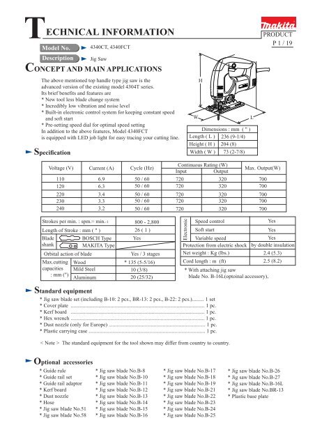
TECHNICAL INFORMATION<br />
Model No.<br />
Description<br />
CONCEPT AND MAIN APPLICATIONS<br />
Specification<br />
<strong>4340CT</strong>, 4340FCT<br />
Jig Saw<br />
The above mentioned top handle type jig saw is the<br />
advanced version of the existing model 4304T series.<br />
Its brief benefits and features are<br />
* New tool less blade change system<br />
* Incredibly low vibration and noise level<br />
* Built-in electronic control system for keeping constant speed<br />
and soft start<br />
* Pre-setting speed dial for optimal speed setting<br />
In addition to the above features, Model 4340FCT<br />
is equipped with LED job light for easy tracing your cutting line.<br />
H<br />
W<br />
L<br />
Dimensions : mm ( " )<br />
Length ( L ) 236 (9-1/4)<br />
Height ( H ) 204 (8)<br />
Width ( W ) 73 (2-7/8)<br />
PRODUCT<br />
P 1 / 19<br />
Voltage (V)<br />
110<br />
120<br />
220<br />
230<br />
240<br />
Current (A)<br />
Cycle (Hz)<br />
6.9 50 / 60<br />
6.3<br />
50 / 60<br />
3.4 50 / 60<br />
3.3<br />
50 / 60<br />
3.2<br />
50 / 60<br />
Continuous Rating (W)<br />
Input<br />
Output<br />
720<br />
720<br />
720<br />
720<br />
720<br />
320<br />
320<br />
320<br />
320<br />
320<br />
Max. Output(W)<br />
700<br />
700<br />
700<br />
700<br />
700<br />
Strokes per min. : spm.= min.-1<br />
Length of Stroke : mm ( " )<br />
Blade<br />
shank<br />
Orbital action of blade<br />
Max.cutting<br />
capacities<br />
: mm (")<br />
BOSCH Type<br />
MAKITA Type<br />
Wood<br />
Mild Steel<br />
Aluminum<br />
800 - 2,800<br />
26 ( 1 )<br />
Yes<br />
Yes / 3 stages<br />
* 135 (5-5/16)<br />
10 (3/8)<br />
20 (25/32)<br />
Electronic<br />
Speed control<br />
Soft start<br />
Variable speed<br />
Protection from electric shock<br />
Net weight : Kg (lbs.)<br />
Cord length : m (ft)<br />
* With attaching jig saw<br />
blade No. B-16L(optoinal accessory),<br />
Yes<br />
Yes<br />
Yes<br />
by double insulation<br />
2.4 (5.3)<br />
2.5 (8.2)<br />
Standard equipment<br />
* Jig saw blade set (including B-10: 2 pcs., BR-13: 2 pcs., B-22: 2 pcs.)......... 1 set<br />
* Cover plate ..................................................................................................... 1 pc.<br />
* Kerf board ..................................................................................................... 1 pc.<br />
* Hex wrench ..................................................................................................... 1 pc.<br />
* Dust nozzle (only for Europe) ......................................................................... 1 pc.<br />
* Plastic carrying case ........................................................................................ 1 pc.<br />
< Note > The standard equipment for the tool shown may differ from country to country.<br />
Optional accessories<br />
* Guide rule<br />
* Guide rail set<br />
* Guide rail adaptor<br />
* Kerf board<br />
* Dust nozzle<br />
* Hose<br />
* Jig saw blade No.51<br />
* Jig saw blade No.58<br />
* Jig saw blade No.B-8<br />
* Jig saw blade No.B-10<br />
* Jig saw blade No.B-11<br />
* Jig saw blade No.B-12<br />
* Jig saw blade No.B-13<br />
* Jig saw blade No.B-14<br />
* Jig saw blade No.B-15<br />
* Jig saw blade No.B-16<br />
* Jig saw blade No.B-17<br />
* Jig saw blade No.B-18<br />
* Jig saw blade No.B-19<br />
* Jig saw blade No.B-21<br />
* Jig saw blade No.B-22<br />
* Jig saw blade No.B-23<br />
* Jig saw blade No.B-24<br />
* Jig saw blade No.B-25<br />
* Jig saw blade No.B-26<br />
* Jig saw blade No.B-27<br />
* Jig saw blade No.B-16L<br />
* Jig saw blade No.BR-13<br />
* Plastic base plate
Features and benefits<br />
<strong>4340CT</strong><br />
4340FCT<br />
P 2 / 19<br />
Incredibly low vibration and noise level<br />
Reciprocating mechanism<br />
unit is highly protected<br />
from saw dust<br />
Superiority to the competitors'products<br />
in cutting speed<br />
See the graph at page 4.<br />
Tough cord guard.<br />
Excellent in flexibility to protect<br />
cable from disconnection<br />
Aluminum gear housing<br />
Kerf board can be attached<br />
for burr-free work<br />
Built in new slider of<br />
squared form for precise<br />
cutting work<br />
LED job light for lighting up<br />
at working point in shadow<br />
(only 4340FCT)<br />
Quick blade change thanks to<br />
new tool less blade clamping system.<br />
Not only BOSCH type but also FESTO's<br />
thick type blade can be attached.<br />
Easily attachable cover plate (plastic) to<br />
protect the surface of sensitive materials,<br />
like as decorative veneers or plastics, etc.<br />
* Optional accessory<br />
Extended service life of back roller<br />
by installing needle bearing<br />
Change lever for selecting<br />
straight + 3 different orbital<br />
cutting action<br />
Adjustable bevel angle 0° - 45°<br />
to left and right<br />
Electronic features<br />
* Soft start<br />
* Keeping constant speed<br />
even under the loaded condition<br />
* Pre-setting dial for variable<br />
speed control<br />
* Pre-setting dial<br />
for speed control<br />
You can enjoy dust-less work<br />
by attaching dust nozzle for<br />
connecting with vacuum cleaner<br />
* Dust nozzle is the standard equipment<br />
for Europe
Comparison of products P 3 /19<br />
Specifications<br />
Power input : W<br />
Model No.<br />
Stroke per min.: spm.(min -1)<br />
Length of stroke : mm (")<br />
Wood : mm<br />
Cutting<br />
(")<br />
capacity<br />
(bevel angle 0°)<br />
Mild steel : mm<br />
(")<br />
Electronic<br />
Pre-setting dial<br />
for speed control<br />
Keeping<br />
constant speed<br />
Orbital action<br />
Blade<br />
shank<br />
B type<br />
M type<br />
Tool less blade<br />
clamping system<br />
LED job light<br />
Connecting with<br />
vacuum cleaner<br />
Vibration : m/s2<br />
Noise : dB (A)<br />
Dimensions<br />
Length : mm<br />
(")<br />
Width : mm<br />
(")<br />
Height: mm<br />
(")<br />
Cord length : m (ft)<br />
Net weight : Kg (lbs)<br />
One action<br />
clamp type<br />
Conventional<br />
type<br />
No loaded<br />
Loaded<br />
No loaded<br />
Loaded<br />
Protection from electric shock<br />
Standard equipments<br />
Plastic carrying case<br />
Blade set<br />
Hex wrench<br />
Dust nozzle<br />
Cover plate<br />
Kerf board<br />
<strong>4340CT</strong> / FCT<br />
720<br />
MAKITA Competitor A Competitor B<br />
800 - 2,800 500 - 3,000<br />
26 (1) 26 (1)<br />
135<br />
(5-5/16)<br />
10<br />
(3/8)<br />
Yes<br />
Yes<br />
Yes<br />
Yes / No<br />
Yes<br />
3.3<br />
8.1<br />
83<br />
85<br />
236<br />
(9-1/4)<br />
73<br />
(2-7/8)<br />
4304T A-1 A-2 B<br />
110<br />
(4-5/16)<br />
10<br />
(3/8)<br />
Yes<br />
No<br />
Yes<br />
No<br />
Yes<br />
86<br />
88<br />
249<br />
(9-3/4)<br />
77<br />
(3)<br />
204<br />
204<br />
(8) (8)<br />
by double<br />
insulation<br />
2.4 (5.3)<br />
600<br />
4.8<br />
11.9<br />
by double<br />
insulation<br />
2.4 (5.3)<br />
580<br />
by double<br />
insulation<br />
650<br />
500 - 3,100 500 - 3,000<br />
26 (1) 26 (1)<br />
110 110<br />
(4-5/16) (4-5/16)<br />
10 10<br />
(3/8) (3/8)<br />
Yes<br />
No<br />
Yes<br />
Yes<br />
Yes<br />
Yes<br />
No No No<br />
77<br />
(3)<br />
by double<br />
insulation<br />
720<br />
1,000 - 2,900<br />
26 (1)<br />
120<br />
(4-3/4)<br />
10<br />
(3/8)<br />
Yes<br />
Yes<br />
Yes<br />
Yes Yes Yes<br />
5.4<br />
7.7<br />
83<br />
86<br />
275<br />
(10-7/8)<br />
81<br />
(3-3/16)<br />
202<br />
(8)<br />
2.4 (5.3)<br />
242<br />
(9-1/2)<br />
197<br />
(7-3/4)<br />
2.3 (5.1)<br />
3.6<br />
8.3<br />
82<br />
88<br />
232<br />
(9-1/8)<br />
71<br />
(2-13/16)<br />
200<br />
(7-7/8)<br />
by double<br />
insulation<br />
2.5 (8.2) 2.5 (8.2) 2.5 (8.2) 4.0 (13.1) 4.0 (13.1)<br />
for Europe<br />
for Europe<br />
2.4 (5.3)<br />
(-Plus type)
Comparison of products P 4 / 19<br />
Numbers in graph below are relative values when setting the capacity of competitor A's Mod.A-1 as 100.<br />
Testing conditions<br />
Jig saw blade Tooth length : 150mm (5-7/8")<br />
B-16L Teeth per inch : 6 T<br />
Setting of orbital<br />
Material<br />
0<br />
Medium Density Fiber Board<br />
Thickness : 40mm (1-9/16)<br />
Testing conditions<br />
Jig saw blade Tooth length : 50mm (2")<br />
B-22 Teeth per inch : 24 T<br />
Setting of orbital<br />
0<br />
SPCC<br />
Material<br />
Thickness : 3.2mm (1/8)<br />
<strong>4340CT</strong><br />
MAKITA,<br />
4340CFT<br />
MAKITA, 4304T<br />
130<br />
90<br />
100<br />
80<br />
Competitor A, A-1<br />
100<br />
100<br />
Competitor B<br />
105<br />
80<br />
0 50 100 150 200<br />
0 50 100 150 200<br />
Testing conditions<br />
Jig saw blade Tooth length : 150mm (5-7/8")<br />
B-16L Teeth per inch : 6 T<br />
Setting of orbital<br />
Material<br />
3<br />
Lauan<br />
Thickness : 90mm (3-1/2)<br />
<strong>4340CT</strong><br />
MAKITA,<br />
4340CFT<br />
MAKITA, 4304T<br />
165<br />
130<br />
Competitor A, A-1<br />
100<br />
Competitor B<br />
130<br />
0 50 100 150 200
Repair P 5 / 19<br />
< 1 > Lubrication<br />
Apply MAKITA grease FA. No.2 to the portions marked with black triangle, and machine oil No.120<br />
to the portions marked with gray triangle to protect parts and product from unusual abrasion.<br />
Gear housing<br />
cover<br />
Linear guide<br />
Balance plate<br />
Gear housing<br />
Gear complete<br />
Push plate<br />
A<br />
B<br />
Pins for supporting<br />
balance plate<br />
Needle bearing 407<br />
Slider<br />
Crank complete<br />
C<br />
Push pin<br />
Rod<br />
Retainer<br />
Blade holder<br />
Lubricant to be applied<br />
MAKITA grease FA. No.2<br />
Machine oil No.120<br />
Parts' name<br />
The portion to be lubricated<br />
Gear housing<br />
The positions painted with gray<br />
Balance plate<br />
The portion where contacts gear complete.<br />
Gear housing cover<br />
The three pins which supports balance plate.<br />
Push plate<br />
The portion where contacts retainer.<br />
Retainer<br />
The portion where contacts push plate.<br />
Linear guides<br />
The portion where contacts slider.<br />
Slider The portion where contacts needle bearing 407.<br />
Push pin<br />
Its whole part<br />
Gear housing cover<br />
The hole where the rod reciprocates.<br />
Rod<br />
The portion where contacts dust seal.
Repair P 6 / 19<br />
< 2 > Disassembling tool opener<br />
1. Separate base from the jig saw unit by unscrewing hex socket head bolt M5x18. See Fig. 1.<br />
2. Unscrew pan head screw M4. Then tool opener and torsion spring 6 can be disassembled. See Fig. 1A.<br />
Fig. 1<br />
Base<br />
Hex socket head bolt M5x18<br />
Torsion spring 6<br />
Tool opener<br />
Pan head screw M4<br />
Fig. 1A<br />
< 3 > Assembling tool opener<br />
1. Put torsion spring 6 into tool opener . And fasten tool opener with pan head screw M4. See Fig. 1A above.<br />
2. Bring the tail of torsion spring 6 which is extruding from tool opener, to the original position by turning it<br />
clockwise. See Fig. 2.<br />
Tool opener<br />
Gear<br />
housing<br />
Blade holder<br />
Gear housing cover<br />
Bottom view<br />
(View from blade holder side)<br />
The tail of<br />
torsion spring 6<br />
Fig. 2<br />
The tail of torsion spring 6 pushed<br />
into the original position.<br />
< 4 > Disassembling handle section (Model 4340T / <strong>4340CT</strong> / 4340FCT)<br />
1. Separate handle R from handle L by unscrewing the following screws. See Fig. 3.<br />
1 pc. of tapping screw 4x40,<br />
1 pc. of tapping screw M4x50<br />
5 pus. of tapping screws 4x8.<br />
< Note in disassembling ><br />
Handles R and L have spikes respectively for fixing on motor housing.<br />
Be careful, not to break them, when disassembling.<br />
5 pus. of tapping screws 4x8. Handle R<br />
Handle L<br />
1 pc. of tapping screw M4x50<br />
1 pc. of tapping screw 4x40,<br />
Fig. 3
Repair P 7 / 19<br />
2. After removing lead wires (black and white) from lead holder, separate handle L from motor housing.<br />
Handle L<br />
Lead wire<br />
(white)<br />
Lead wire<br />
(black)<br />
Motor housing<br />
Brush holders<br />
Fig. 4<br />
< 5 > Disassembling gear housing cover section<br />
1.After taking off safety wire from gear housing cover, unscrew 4 pcs. of tapping screws CT 4 x 16.<br />
Then, gear housing cover can be separated from gear housing. See Fig. 5.<br />
4 pcs. of<br />
Tapping screws CT 4 x 16<br />
Gear housing cover<br />
Safety wire<br />
4340T, <strong>4340CT</strong>, 4340FCT<br />
Fig. 5<br />
2.Take off stop ring E-3 with small flat head screwdriver. And push slider to the lower dead point. See Fig. 6.<br />
Stop ring E-3<br />
Slider<br />
Pin 4<br />
Rod<br />
Rod<br />
Slider in the lower<br />
dead point<br />
Fig. 6
Repair P 8 / 19<br />
3.Slide pin 4 in order to disconnect rod with slider. And then, pull out rod from gear housing cover.<br />
Disassemble linear guides by unscrewing 4 ps. of pan head screws M4 x 10. So, leaf spring, pin 4 and slider can be<br />
disassembled from gear housing cover. See Fig. 7.<br />
Linear guides<br />
Gear housing<br />
cover<br />
Slider<br />
Slider<br />
Pin 4<br />
Pin 4<br />
Linear guides<br />
Leaf spring<br />
4 ps. of<br />
Pan head<br />
screws M4 x 10<br />
Rod<br />
Fig. 7<br />
< 6 > Assembling gear housing cover section<br />
1. Assemble tool opener to gear housing cover with referring to Fig. 1A and Fig. 2 at page 6.<br />
2. Put leaf spring in gear housing cover, paying attention to its assembling direction as illustrated in Fig. 8.<br />
And insert rod into gear housing cover, paying attention to the direction of hook of blade holder<br />
as illustrated in Fig. 8A.<br />
Tool opener<br />
Gear housing cover.<br />
Leaf spring<br />
Blade holder<br />
The rolling portion has to be<br />
faced to gear housing side.<br />
Gear housing side<br />
Blade<br />
holder<br />
Rod<br />
Gear housing cover<br />
Tool opener<br />
Blade holder's hook has<br />
to contact with tool opener,<br />
when detaching the blade<br />
with tool opener.<br />
Fig. 8<br />
Blade holder's hook<br />
Fig. 8A
Repair P 9 / 19<br />
3. Align the hole of slider and the same of rod, and insert pin 4 into the aligned holes from left side as illustrated<br />
in Fig. 9.<br />
Stand slider and insert a pair of linear guide as illustrated in Fig. 9A.<br />
Rod inserted into<br />
gear housing cover<br />
Slider, stood for setting<br />
a pair of linear guide<br />
Linear guides<br />
Slider<br />
Rod<br />
Slider<br />
Fig. 9<br />
Pin 4<br />
(Insert it from left side.)<br />
Slider<br />
Rod<br />
Fig. 9A<br />
4. Lifting up leaf spring, lay a pair of linear guide in order to position leaf spring on linear guides as illustrated<br />
in Fig. 10.<br />
And push slider to the center of linear guides. Fasten linear guides with 4 pcs. of pan head screws<br />
M4 x 10 as illusdtrated in Fig. 10A.<br />
Lay linear guides.<br />
Slider<br />
Lift up leaf spring.<br />
Pan head screws M4x10<br />
Push slider to the<br />
center of linear guides.<br />
Fig. 10<br />
Linear guide<br />
Leaf spring<br />
Fig. 10A<br />
5. Assemble stop ring E-3 to pin 4 as illustrated in Fig. 11.<br />
Check, whether slider can reciprocate on linear guide smoothly, or not.<br />
If slider does not reciprocate smoothly, incorrectly assembled linear guides can interfere with slider<br />
in reciprocating. Try again to assemble linear guides correctly.<br />
Stop ring E-3<br />
Linear guide<br />
Slider<br />
Pin 4<br />
Rod<br />
Fig. 11
Repair P 10 / 19<br />
5. Lubricate the parts assembled in gear housing cover with referring to "< 1 > Lubrication " at page 5.<br />
6. Aligning slider to needle bearing 407 on crank complete, assemble gear housing cover section to gear housing<br />
as illustrated in Fig. 11 . Do not forget to assemble packing between gear housing cover<br />
and gear housing. See Fig.11A<br />
4 pcs. of<br />
Tapping screws CT 4 x 16<br />
Needle bearing 407<br />
Gear housing cover<br />
Slider<br />
Packing<br />
Gear housing<br />
cover<br />
Align slider to needle bearing 407<br />
on crank complete<br />
Fig. 11<br />
Crank complete<br />
Balance plate<br />
Gear housing<br />
Safety wire<br />
4340T, <strong>4340CT</strong>, 4340FCT<br />
Fig. 11A<br />
< 7 > Disassembling blade holder<br />
1. Disassemble rod with referring to "< 5 > Disassembling gear housing cover section" at page 8.<br />
2. Disassemble dust cover, and then disassemble retaining ring R-18. as illustrated in Fig. 12.<br />
So blade holder and torsion spring 15 can be separated from rod as illustrated in Fig. 12A.<br />
Dust cover<br />
Retaining<br />
ring R-18<br />
Be careful, not to lose push pin,<br />
when disassembling.<br />
Rod<br />
Torsion spring 15<br />
Blade holder<br />
Blade holder<br />
Fig. 12<br />
Fig. 12A<br />
< 8 > Assembling blade holder<br />
1. Apply MAKITA grease FA No.2 to push pin and set it in the hole of rod. And assemble torsion spring 15 to rod by<br />
inserting its tail shown in Fig. 13 into the hole of rod.<br />
2. Set blade holder to rod as illustrated in Fig. 14. And bring the tail of torsion spring 15 to the space A of blade<br />
holder as illustrated in Fig. 15.<br />
Bring this tail to the<br />
space A of blade<br />
Rod<br />
holder by turning<br />
clockwise.<br />
Push pin<br />
Torsion spring 15<br />
Space A<br />
Blade holder<br />
Insert this tail into<br />
the hole of rod.<br />
Fig. 13<br />
Aligning the mark<br />
of blade holder and<br />
push pin, set blade holder<br />
to rod.<br />
Fig. 14<br />
Fig. 15
Repair P 11 / 19<br />
3. Push rod into blade holder, and assemble retaining ring R-18 to the groove in blade holder as illustrated in Fig. 16.<br />
4. Assemble dust cover as illustrated in Fig.17.<br />
Retaining ring R-18<br />
Dust cover<br />
Press dust cover to assemble<br />
firmly to blade holder.<br />
Fig. 16<br />
Fig.17<br />
< 9 > Disassembling parts in gear housing<br />
1. After taking off safety wire from gear housing cover, unscrew 4 pcs. of tapping screws CT 4 x 16.<br />
Separate gear housing cover from gear housing. See Fig. 18.<br />
4 pcs. of<br />
Tapping screws CT 4 x 16<br />
Gear housing cover<br />
Safety wire<br />
Fig. 4<br />
4340T, <strong>4340CT</strong>, 4340FCT<br />
Fig. 18<br />
2. Locking crank complete with something bar-formed metal, unscrew 2 pcs. of hex socket head bolts M4 x 12 as<br />
illustrated in Fig.19.<br />
3. Disassemble retaining ring S-8. Then, the inner parts can be disassembled from gear housing as illustrated in Fig.20.<br />
< Note in disassembling><br />
2 pcs. of hex socket head bolts M4 x 12 are adhesive bolts.<br />
It is recommended to unscrew them with impact driver.<br />
No.1R235<br />
Round bar for arbor<br />
2 pcs. of hex socket<br />
head bolts M4 x 12<br />
Retaining ring S-8<br />
Crank complete<br />
Balance plate<br />
Needle bearing 407<br />
Flat washer 8<br />
Balance plate<br />
Retaining ring S-8<br />
Fig.19<br />
Crank complete<br />
Gear complete<br />
Push plate<br />
Seal plate<br />
Fig.20<br />
Gear housing
Repair P 12 / 19<br />
< 10 > Assembling parts in gear housing<br />
1. Assemble flat washer 8 to the shaft in gear housing. See Fig. 21.<br />
2. After assembling seal plate to push plate, assemble them to the shaft in gear housing. See Fig. 22.<br />
3. Lubricate the parts with referring to " < 1 > Lubrication " at page 5.<br />
4. Assemble gear complete and balance plate to the shaft in gear housing. See Fig. 23.<br />
5. Assemble crank complete to gear housing. With turning crank complete, press it down to the position in which<br />
you can see the shaft's groove for retaining ring S-8. See Fig. 24.<br />
( With turning crank complete, press it down to the position in which<br />
you can see the shaft's groove for retaining ring S-8. )<br />
6. Lock crank complete with something like 1R235 "round bar for arbor", and fasten crank complete<br />
with 2 pcs. of hex socket head bolts M4 x 12 with adhesive. See Fig. 25.<br />
< Note ><br />
Do not fasten with the used hex socket head bolts M4 x 12. The fresh adhesive hex socket head bolts M4 x 12<br />
have to be used. The fastening torque of these bolts is 2.4 - 3.5 N.m.<br />
7. Assemble retaining ring S-8 to the shaft of gear housing. See Fig. 26.<br />
Flat washer 8<br />
Balance plate<br />
Gear complete<br />
Gear housing<br />
Push plate<br />
Seal plate<br />
Gear housing<br />
Gear housing<br />
Fig.21 Fig.22 Fig.23<br />
Press crank complete down to the position where<br />
you can see the shaft's groove for retaining ring S-8.<br />
Groove for retaining<br />
Crank ring S-8<br />
complete<br />
Something like<br />
1R235 "round bar<br />
for arbor"<br />
2 pcs. of hex socket<br />
head bolts M4 x 12<br />
Fig. 24<br />
Retaining ring S-8<br />
Balance plate Retaining ring S-8<br />
Fig. 25<br />
Crank complete<br />
Fig. 26<br />
Crank complete<br />
Balance plate<br />
Gear complete<br />
Push plate<br />
Flat washer 8<br />
Seal plate
Repair P 13 / 19<br />
< 11 > Disassembling armature (4340T, <strong>4340CT</strong>, 4340FCT)<br />
1. With referring to the following section, disassemble handle L and R, and gear housing cover.<br />
"< 4 > Disassembling handle section" at page 6<br />
"< 5 > Disassembling gear housing cover section" at page 7<br />
2. Disassemble retaining ring S-8, and separate crank complete and balance plate from the shaft of gear housing<br />
as illustrated in Fig. 27.<br />
< Note in disassembling ><br />
* No need to disassembling hex socket head bolt M4 x 12 and crank complete from balance plate.<br />
* Be careful, not to lose needle bearing 407.<br />
Needle bearing 407<br />
Retaining S-8<br />
Crank complete<br />
Gear complete<br />
Balance plate<br />
Fig. 27<br />
3. Unscrew 4 pcs. of tapping screws M4 x 30, and separate gear housing from motor housing.<br />
Separate armature from gear housing as illustrated in Fig. 28.<br />
4 pcs. of<br />
tapping screws<br />
M4 x 30<br />
Gear housing<br />
Armature<br />
Motor housing<br />
Fig. 28<br />
4. Disassemble self lock with small flat head screwdriver. Then, magnet sleeve, wave washer 6 and rubber ring 19<br />
can be disassembled from armature shaft as illustrated in Fig. 29.<br />
Self lock<br />
Fig. 29<br />
Insulation washer<br />
Ball baring 607<br />
Rubber ring 19<br />
Wave washer 6<br />
Magnet sleeve<br />
(Magnet sleeve is not used in<br />
model 4341T.)<br />
5. Disassemble ball bearing 607 LLB from armature shaft as illustrated in Fig. 30.<br />
No.1R269 Bearing extractor<br />
Ball bearing 607 LLB<br />
Insulation washer<br />
Fig. 30
Repair P 14 / 19<br />
< 12 > Disassembling lever 17 ( for orbital action mode change)<br />
1. With referring to the following section, disassemble handle L and R, or head cover L and R, and gear housing cover.<br />
"< 4 > Disassembling handle section" at page 6 (for 4340T, <strong>4340CT</strong>, 4340FCT)<br />
"< 5 > Disassembling gear housing cover section" at page 7<br />
2. Disassemble stop ring E-5 from the shaft portion of lever 17 with small flat head screwdriver. See Fig. 35.<br />
3. Aligning lever 17 with indication " III ", pull out it from gear housing. Then, cap 5 and compression spring 3<br />
are disassembled. See Fig. 35.<br />
Compression<br />
spring 3<br />
Cap 5<br />
Stop ring E-5<br />
Align lever 17 with indication " III ".<br />
Fig. 35<br />
Lever 17
Circuit diagram<br />
P 15 / 19<br />
Model 4340FCT (with controller and LED job light)<br />
Model <strong>4340CT</strong> ( with controller, without LED job light)<br />
Black<br />
White<br />
Red<br />
Color index of lead wires<br />
Orange<br />
Blue<br />
Instead of terminal block,<br />
insulated terminal is used<br />
in the products for some<br />
countries.<br />
In stead of blue, white lead wire<br />
is used in the product for some<br />
countries.<br />
Controller<br />
Insulated<br />
terminal<br />
3<br />
2<br />
Switch<br />
Power supply cord<br />
Terminal block<br />
The orange lead wire is not<br />
used in the product for low<br />
voltage area.<br />
Pick-up coil<br />
Connect field lead wire (white)<br />
through insulated terminal as follows,<br />
when repairing.<br />
Field<br />
Noise<br />
suppressor<br />
(Noise suppressor is not<br />
used in some countries.)<br />
LED<br />
Job light<br />
LED job light is not<br />
installed in model <strong>4340CT</strong><br />
and 4341CT.<br />
Controller lead wire<br />
(Orange)<br />
Field lead wire (white)<br />
Insulated<br />
terminal<br />
Field<br />
Connecting<br />
lead wire (white)
Circuit diagram<br />
P 16 / 19<br />
Model 4340T (without controller andt LED circuit)<br />
Color index of lead wires<br />
Black<br />
White<br />
See-through<br />
Instead of terminal block,<br />
insulated terminal is used<br />
in the products for some<br />
countries.<br />
3<br />
2<br />
Switch<br />
Power supply cord<br />
Terminal block<br />
Field<br />
Noise<br />
suppressor<br />
(Noise suppressor is not<br />
used in some countries.)<br />
To be connected to<br />
field core.
Wiring diagram in motor housing<br />
4340T, <strong>4340CT</strong> and 4340FCT<br />
Side A<br />
P 17 / 19<br />
Side D<br />
Side B<br />
Side C<br />
Side D<br />
Fix lead wires from<br />
the rear portion of<br />
motor housing to handle,<br />
with lead holder.<br />
Side A<br />
And do not slack the<br />
lead wires in motor housing.<br />
Side C<br />
Side B<br />
Fix the lead wires with<br />
lead holders.<br />
Side C<br />
Field lead wire<br />
(Black)<br />
Side A<br />
Field lead wire<br />
(Black)<br />
Field lead wire<br />
(White)<br />
Controller's<br />
lead wire (Orange), which is<br />
not used in the products for<br />
low voltage area.<br />
Grounding lead wire<br />
(See-through) to be connected<br />
to field core
Wiring diagram in handle section P 18 / 19<br />
<strong>4340CT</strong> (with controller, without LED jog light)<br />
4340FCT (with controller and LED jog light)<br />
Put slack portion of lead wires<br />
between pins.<br />
Roll the slack portion of LED lead<br />
wire around lead holders.<br />
Lead holder<br />
Pin<br />
Controller<br />
Terminal block<br />
Switch<br />
Noise suppressor<br />
Pick-up coil<br />
Rib<br />
Wall<br />
Brush holders<br />
LED Job light<br />
(for 4340FCT)<br />
Field lead wire<br />
(black)<br />
Pass lead wires between wall<br />
and rib.<br />
Field lead wire<br />
(white)<br />
Field lead wire<br />
(black)
Wiring diagram in handle section<br />
P 19 / 19<br />
4340T (without controller, without LED jog light)<br />
Rib<br />
Wall<br />
Pass lead wires between wall<br />
and rib.<br />
Field lead wire<br />
(black)<br />
Field lead wire<br />
(white)<br />
Field lead wire<br />
(black)<br />
Grounding lead wire<br />
( See-through)