P0510 EN EZH-B Control Unit - TROMA-MACH sro
P0510 EN EZH-B Control Unit - TROMA-MACH sro
P0510 EN EZH-B Control Unit - TROMA-MACH sro

Create successful ePaper yourself
Turn your PDF publications into a flip-book with our unique Google optimized e-Paper software.
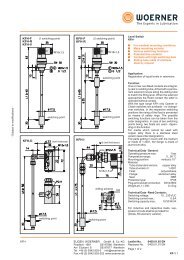
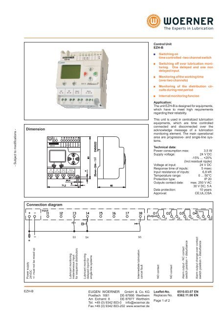
<strong>Control</strong> <strong>Unit</strong><br />
<strong>EZH</strong>-B<br />
<strong>EZH</strong>-B<br />
E 3<br />
E 4<br />
E 5<br />
Switching on<br />
time controlled - two channel switch<br />
<br />
Switching off over lubrication monitoring.<br />
One delayed and one non<br />
delayed input.<br />
<br />
Monitoring of the working time<br />
(over two channels)<br />
AZ<br />
13 14<br />
AZ<br />
23 24<br />
Alarm<br />
43 44<br />
Alarm<br />
31 34 32<br />
<br />
<br />
Monitoring of the distribution circuits<br />
during rest period<br />
Internal monitoring funcion<br />
Application:<br />
The unit <strong>EZH</strong>-B is designed for equipments,<br />
which have to meet high requirements<br />
regarding their reliability.<br />
- Subject to modifications -<br />
Dimension<br />
<strong>EZH</strong>-B<br />
AZ AZ<br />
13 14 23 24<br />
Alarm<br />
43 44<br />
E 3<br />
E 4<br />
Alarm<br />
31 34 32<br />
E 5<br />
rail<br />
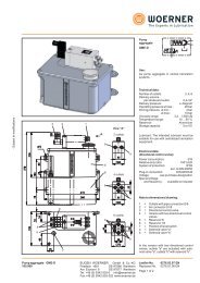
This unit is used in centralized lubrication<br />
equipments, which are time controlled<br />
connected and disconnected over the<br />
acknowledge message of a lubrication<br />
monitoring element. The main operational<br />
area are progressive- and single-line systems.<br />
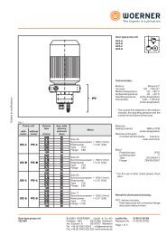
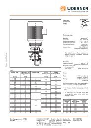
Technical data:<br />
Power consumption max: 3,5 W<br />
Supply voltage:<br />
24 V DC<br />
-15% ... +20%<br />
(Incl.residual ripple)<br />
Voltage at input:<br />
24 V DC<br />
Response time of inputs: 5 msec<br />
Input resistance of inputs: 6,8 kR<br />
Temperature range: 0 ... 50°C<br />
Protection type: IP 20<br />
Outputs contact data: max. 250 V AC<br />
30 V DC; 5 A<br />
Data protection:<br />
10 years<br />
Approval:<br />
CE;UL;CSA<br />
Connection diagram<br />
Input<br />
Output<br />
13 14 23 24 43 44 31 34 32<br />
P<br />
Power supply<br />
24VDC<br />
+/- must not be mixed up<br />
S3 S4 S5<br />
Lubricant monitoring<br />
instantaneous input<br />
for sequence distributors<br />
Lubricant monitoring<br />
delayed input for<br />
single-line systems<br />
Intermediate lubrication<br />
cancel fault<br />
NO contact<br />
NO contact<br />
Alarm output - NC contact<br />
switch position = disturbance<br />
Alarm output change-over contact<br />
switch position = disturbance<br />
<strong>EZH</strong>-B<br />
EUG<strong>EN</strong> WOERNER GmbH & Co. KG<br />
Postfach 1661 DE-97866 Wertheim<br />
Am Eichamt 8 DE-97877 Wertheim<br />
Tel. +49 (0) 9342 803-0 info@woerner.de<br />
Fax.+49 (0) 9342 803-202 www.woerner.de<br />
Leaflet-No.<br />
Replaces No.<br />
Page 1 of 2<br />
0510.03.07 <strong>EN</strong><br />
0362.11.00 <strong>EN</strong>
1.Switch-ON-conditions<br />
1.1 <strong>Control</strong> supply ON -Prelubrication:<br />
When the control supply is energized, the<br />
prelubrication is initiated. (If the control<br />
power supply is temporarily interrupted it<br />
must remain interrupted for more than 1<br />
sec.)<br />
1.2 Intermediate lubrication<br />
Intermediate lubrication can be initiated by<br />
closing a contact at E5/24V.<br />
1.3 Time ON:<br />
The unit is provided with two time standards,<br />
which are independent from each<br />
other. Every time standard a set value is<br />
allocated to.Both set values (channel 1 and<br />
channel 2) must always be set to the same<br />
value. When the set time is concurrent, the<br />
working memory associated with the channel<br />
is set. When both working memories are<br />
set, the working relay will be triggered.<br />
Time range: 1 to 32,767 seconds.<br />
2. Switch - off conditions:<br />
The signal from a lubricant monitoring<br />
device ends the operating time. The inputs<br />
E3/E4 are dynamic, i.e. the unit only detects<br />
the positive change in signal.<br />
2.1 Input E3 instantaneous<br />
Input E3 must be used for progressive<br />
systems.<br />
2.2 Input E4 delayed<br />
Input E4 must be used for single-line systems.<br />
The switch-off signal is delayed by 0,5<br />
to 1 sec.<br />
3. Monitoring<br />
3.1 Operating time, channel 1<br />
The setting of the main store for channel 1<br />
causes the monitoring time for channel 1 to<br />
start running in the unit. The main store<br />
must be reset within the preset monitoring<br />
time so that no fault alarm is given. The fault<br />
store is reset if there is a fault alarm. The<br />
alarm relay drops out. The monitoring time<br />
can be 60 or 300 sec. (see order designation)<br />
3.2 Operating time, channel 2<br />
The monitoring for channel 2 runs separately<br />
from channel 1 but has the same function.<br />
3.3 Distributor cycles during idle time<br />
During idle time the pulses at E3 are counted<br />
and a fault alarm is given if 8 are received.<br />
3.4 Counter monitoring<br />
The separation of the two channels 1 and 2<br />
combined with the monitoring time for each<br />
channel allows the counters to be monitored.<br />
Example:<br />
Channel 1 is working without any faults. the<br />
main store of channel 1 is set. The monitoring<br />
time is started. If the second main store<br />
is not set due to a fault in channel 2, the<br />
operating relay is not energized and so<br />
there is no reset pulse from the lubrication<br />
system. Channel 1 signals a fault.<br />
Since the operating time monitoring also<br />
incorporates monitoring of the counters, it is<br />
possible that the two counters do not have<br />
to work exactly in synchronism and a small<br />
difference is allowed.<br />
3.5 Fault Memory<br />
There are three fault memories available.<br />
When switching the unit on, the alarm relay<br />
is energised. In the presence of any failure<br />
the relevant fault memory is reset, whilst the<br />
alarm relay drops out.<br />
3.6 Fault alarm cancel<br />
The fault alarm can be cancelled via input<br />
E5/24V and a new lubrication cycle is initiated<br />
at the same time.<br />
4. Outputs<br />
4.1 Operating relay contacts:<br />
There are two floating NO contacts for<br />
triggering the solenoid valve or pump.<br />
Terminals. 13/14; 23/24.<br />
4.2Alarm output:<br />
For the alarm outputs a potential-free N/O<br />
contact and a changeover contact are<br />
available. In flawless operation, the alarm<br />
relay is pulled in.<br />
- Subject to modifications -<br />
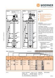
Operation<br />
ESC<br />
+<br />
OK<br />
Desired value adjustement<br />
The desired values can be adjusted as<br />
follows:<br />
B<br />
Keep button pressed<br />
for 5 seconds<br />
5. Monitoring devices<br />
Both floating contacts and proximity sensors<br />
can be used as monitoring devices.<br />
The proximity sensors should be suitable<br />
for 24VDC and possess a PNP output.<br />
A<br />
B<br />
-<br />
Re-adjust<br />
flashing bar<br />
No<br />
-<br />
Yes<br />
Press button<br />
OK<br />
+<br />
Set value<br />
Next bar<br />
value<br />
-<br />
? +<br />
Order designation:<br />
<strong>Control</strong> unit<br />
<strong>EZH</strong>-B/060/24VDC<br />
<strong>EZH</strong>-B/300/24VDC<br />
453.904-60<br />
453.905-60<br />
OK<br />
Press<br />
button<br />
Indication:<br />
Setting mode will be finished automatically after1 minute, when re-adjustment was<br />
completed by pressing OK (flashing bar)<br />
Esc Can be used to cancel the operation.<br />
Caution: Do not set any zero or negative value!<br />
Use power pack in case of 230VAC<br />
operating voltage !!!<br />
Power pack purchase designation:<br />
100-240VAC/24VDC 1,2A 974.101-30<br />
EUG<strong>EN</strong> WOERNER GmbH & Co. KG<br />
Postfach 1661 DE-97866 Wertheim<br />
Am Eichamt 8 DE-97877 Wertheim<br />
Tel. +49 (0) 9342 803-0 info@woerner.de<br />
Fax.+49 (0) 9342 803-202 www.woerner.de<br />
Leaflet-No.<br />
Page 2 of 2<br />
0510 <strong>EN</strong>