Gear Couplings New.qxp - TROMA-MACH sro
Gear Couplings New.qxp - TROMA-MACH sro
Gear Couplings New.qxp - TROMA-MACH sro

You also want an ePaper? Increase the reach of your titles
YUMPU automatically turns print PDFs into web optimized ePapers that Google loves.
<strong>Gear</strong> <strong>Couplings</strong><br />
G<br />
!<br />
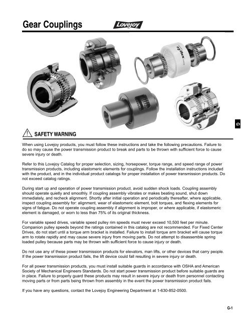
SAFETY WARNING<br />
When using Lovejoy products, you must follow these instructions and take the following precautions. Failure to<br />
do so may cause the power transmission product to break and parts to be thrown with sufficient force to cause<br />
severe injury or death.<br />
Refer to this Lovejoy Catalog for proper selection, sizing, horsepower, torque range, and speed range of power<br />
transmission products, including elastomeric elements for couplings. Follow the installation instructions included<br />
with the product, and in the individual product catalogs for proper installation of power transmission products. Do<br />
not exceed catalog ratings.<br />
During start up and operation of power transmission product, avoid sudden shock loads. Coupling assembly<br />
should operate quietly and smoothly. If coupling assembly vibrates or makes beating sound, shut down<br />
immediately, and recheck alignment. Shortly after initial operation and periodically thereafter, where applicable,<br />
inspect coupling assembly for: alignment, wear of elastomeric element, bolt torques, and flexing elements for<br />
signs of fatigue. Do not operate coupling assembly if alignment is improper, or where applicable, if elastomeric<br />
element is damaged, or worn to less than 75% of its original thickness.<br />
For variable speed drives, variable speed pulley rim speeds must never exceed 10,500 feet per minute.<br />
Companion pulley speeds beyond the ratings contained in this catalog are not recommended. For Fixed Center<br />
Drives, do not start until a torque arm bracket is installed. Failure to install torque arm bracket will cause torque<br />
arm to rotate rapidly and may cause severe injury from moving parts. Do not attempt to disassemble spring<br />
loaded pulley because parts may be thrown with sufficient force to cause injury or death.<br />
Do not use any of these power transmission products for elevators, man lifts, or other devices that carry people.<br />
If the power transmission product fails, the lift device could fall resulting in severe injury or death.<br />
For all power transmission products, you must install suitable guards in accordance with OSHA and American<br />
Society of Mechanical Engineers Standards. Do not start power transmission product before suitable guards are<br />
in place. Failure to properly guard these products may result in severe injury or death from personnel contacting<br />
moving parts or from parts being thrown from assembly in the event the power transmission product fails.<br />
If you have any questions, contact the Lovejoy Engineering Department at 1-630-852-0500.<br />
G-1
<strong>Gear</strong> <strong>Couplings</strong><br />
General Overview<br />
Lovejoy/Sier-Bath <strong>Gear</strong> <strong>Couplings</strong><br />
Lovejoy offers a variety of designs and models in its gear coupling family.<br />
From standard, off-the-shelf stock to new, high speed, special designs,<br />
Lovejoy can satisfy your gear coupling needs.<br />
Continuous and Flanged Sleeve<br />
The original Continuous Sleeve, or “C”, coupling offers a lightweight,<br />
compact, and simple design without compromising torque carrying capacity.<br />
The Flanged Sleeve, or “F”, coupling is available in exposed or shrouded<br />
bolt styles in which the number of bolts, size of bolts, and bolt circle are<br />
identical with industry standards. Within these two basic product lines,<br />
modifications and variations exist to serve a wide variety of applications<br />
such as extended distances between shaft ends, Mill Motors, limited end<br />
float, or vertical. Many designs can be created for unique applications as<br />
well.<br />
CONTINUOUS SLEEVE GEAR COUPLING<br />
G<br />
Nylon Sleeve<br />
The nylon sleeve gear couplings, Nyflex and Mite, are compact, lightweight<br />
couplings that use a nylon sleeve and two sintered iron hubs. Lubrication is<br />
not required with the nylon sleeve. With speeds up to 5,000 RPM, the nylon<br />
sleeve gear couplings are effectively used in applications such as<br />
motor/generator sets, motor/pump sets, and many other light duty industrial<br />
settings.<br />
All Metal Labyrinth Seal and Alloy Steel<br />
In addition to the Lovejoy/Sier-Bath Continuous Sleeve, Flanged Sleeve,<br />
and nylon sleeve couplings, Lovejoy has an All Metal Labyrinth Seal<br />
coupling and an Alloy Steel coupling. The All Metal Labyrinth Seal coupling,<br />
or “FLA”, is a flanged sleeve style but uses no elastomeric seals. The Alloy<br />
Steel coupling, or FA, is made from AISI 4140 steel. It is based on the<br />
standard “F” coupling, but it has a special seal and grade 8 bolts.<br />
FLANGED SLEEVE GEAR COUPLING<br />
Lovejoy maintains a large inventory of “C”, “F”, “FLA”, and “FA” couplings in<br />
both rough bore and pre-bored forms. In addition, Lovejoy can bore to your<br />
specifications. Challenge us with your applications and let us serve your<br />
needs.<br />
G-2<br />
!<br />
WARNING<br />
You must refer to page G-1 for Important Safety Instructions and Precautions<br />
for the selection and use of these products. Failure to follow the instructions<br />
and precautions can result in severe injury or death.
<strong>Gear</strong> <strong>Couplings</strong><br />
Overview<br />
Lovejoy/Sier-Bath Continuous Sleeve Series<br />
Absorbs Misalignment, End-Float<br />
The basic principle of the Lovejoy/Sier-Bath <strong>Gear</strong> Coupling is similar to that<br />
of conventional flexible gear couplings. While it is desirable to align shafts<br />
as accurately as possible, the purpose of any flexible coupling is to absorb<br />
probable misalignment (angular and offset), and end-float. The<br />
Lovejoy/Sier-Bath Coupling accomplishes this through the rocking action of<br />
the hubs in the sleeve.<br />
Simplified Method of Closure<br />
The essential difference between the Lovejoy/Sier-Bath Coupling and<br />
conventional types is its simplified design. This is made possible by the<br />
advanced assembly and lubrication sealing arrangement, which eliminates<br />
the need for cumbersome flanges, bolts and nuts. BUNA N lubrication<br />
seals and steel snap rings hold in the lubricant and provide the means<br />
of assembly.<br />
Standard Types and Sizes<br />
Lovejoy/Sier-Bath <strong>Couplings</strong> are stocked in Standard, Mill Motor, Vertical,<br />
Floating Shaft and Spacer Types—sizes 7 / 8 to 12, to accommodate bores up<br />
to 12.50. Load capacities range from 4 to 4,000 HP per 100 RPM.<br />
Two Hubs — One Sleeve<br />
Major components are machined from medium carbon steel. <strong>Gear</strong> teeth are<br />
precision cut 20º pressure angle with minimum backlash and are smaller<br />
for even distribution of load, greater capacity, and longer life. Interference fit<br />
on bore is standard.<br />
Two Seals<br />
The seals are made of BUNA N with two reinforcing washers bonded to the<br />
inside faces which positively retain lubricant and seal interior against<br />
foreign matter. Seals are patented Lovejoy/Sier-Bath design and are tested.<br />
G<br />
Special Types and Sizes<br />
Many special types have been manufactured, such as Brakedrum Type,<br />
Sliding Hub Type, Jordan Type, etc. Specifications on sizes larger than<br />
standard are available. Size range is virtually unlimited. Exceptional<br />
simplicity makes great design flexibility possible. Unusual requirements<br />
can also be met.<br />
Two Snap Rings<br />
The spiral wound rings are made of oil hardened spring steel and securely<br />
hold the coupling together. Each ring is simple to install and remove yet<br />
withstands over 100,000 pounds of end-thrust.<br />
Features and Benefits of Continuous Sleeve Type <strong>Couplings</strong><br />
Simple and inexpensive type of gear coupling.<br />
All steel sleeves and hubs.<br />
Reinforced rubber seals with steel snap rings to hold lubricant in place.<br />
Available as vertical and horizontal couplings.<br />
Wide variety of special variations available such as full-flex, flex–rigid, mill<br />
motor, floating shaft and spacer types.<br />
Standard configurations are available off-the-shelf.<br />
G-3
<strong>Gear</strong> <strong>Couplings</strong><br />
Overview<br />
Lovejoy/Sier-Bath Continuous Sleeve Series<br />
Standard Type<br />
This is the basis for all types of Lovejoy/Sier-Bath Continuous Sleeve<br />
Flexible <strong>Gear</strong> <strong>Couplings</strong>, and it is suitable for most applications. Great<br />
simplicity allows inexpensive adaptation to a wide variety of special types.<br />
Mill Motor Type<br />
Designed specifically for mill motors with tapered shafts, one hub is<br />
taper bored to the customer’s specifications. This longer hub is<br />
counterbored for the nut on the end of the motor shaft. The sleeve and<br />
other hub are standard.<br />
G<br />
Floating Shaft Type<br />
Two Flex-Rigid couplings connected by an intermediate shaft serve remote<br />
drive and excessive misalignment problems. Usually the coupling hubs on<br />
the driver and driven ends are rigid while the two center hubs connected by<br />
the center shaft are flexible. These hubs can be reversed, if necessary,<br />
without sacrificing ease of installation or disassembly.<br />
Spacer Type<br />
Spacer couplings are used in applications where it becomes necessary to<br />
remove the hubs from either shaft without disturbing the mountings of the<br />
connected units. The hubs on both the driven and driver shaft are flexible<br />
and the spacer has spline teeth to mate with the sleeves of each coupling.<br />
Cut-out Type<br />
Designed to permit quick disengagement between the driver and driven<br />
shafts without disassembling the coupling, this coupling is widely used on<br />
dual drives and on equipment operated in tandem. A special seal is<br />
provided on the disengaged hub to eliminate undue friction when the hub<br />
is turning in the sleeve. Cut-out Type couplings are also available with pins<br />
to maintain the sleeves in both engaged and disengaged positions.<br />
Shear Pin Type<br />
Shear pin couplings are designed to limit excessive torque or sudden shock<br />
loads. The shear pins in the Lovejoy/Sier-Bath Coupling are designed and<br />
manufactured to shear at predetermined loads and are in hardened<br />
bushings. <strong>New</strong> pins may be quickly inserted.<br />
G-4
<strong>Gear</strong> <strong>Couplings</strong><br />
Overview<br />
Lovejoy/Sier-Bath Flanged Sleeve Series<br />
Misalignment and End-Float Capability<br />
The Lovejoy/Sier-Bath Flanged Sleeve gear coupling is a flexible coupling<br />
that compensates for angular misalignment, parallel misalignment, and end<br />
float. Angular and parallel misalignment, and combinations thereof, will<br />
result in angular misalignment at the gear mesh. Lovejoy/Sier-Bath Flanged<br />
Sleeve couplings can accommodate 1¹⁄₂º of relative angular misalignment<br />
in each gear mesh up to size 5¹⁄₂. Sizes 6 and larger can accommodate ³⁄₄º<br />
of angular misalignment at each gear mesh. The hub teeth are fully<br />
crowned to provide for a larger contact area and lower stresses under<br />
misaligned conditions. The crowned tooth design also avoids the end<br />
loading that occurs on straight teeth under misalignment.<br />
Features and Benefits of Flanged Sleeve <strong>Couplings</strong><br />
Patented Vari-Crown® tooth form for long life.<br />
Standard 20º pressure angle.<br />
Heat treated bolts for greater strength.<br />
Bolts and nuts are coated for corrosion resistance and ease of<br />
maintenance.<br />
Interchangeable with industry standards.<br />
Large bore and torque capacities.<br />
Piloted gear fit for higher speeds and less vibration.<br />
Interference fit on bore is standard.<br />
G<br />
Standard and Special Types and Sizes<br />
The standard Flanged Sleeve series is offered in exposed and shrouded<br />
bolt patterns through size 5¹⁄₂. The exposed bolt pattern is available for<br />
sizes larger than size 6. It has the same number of bolts, size of bolts, and<br />
bolt circle as industry standards up to size 7. Heat treated bolts are plated<br />
for corrosion resistance.<br />
Modifications and variations of the standard Flanged Sleeve coupling exist<br />
to suit specific or unique applications. Sizes can go as large as size 30<br />
which can accommodate up to 54” bores. Insulated couplings, Jordan<br />
types, extended slide, vertical, brakedrum, and continuously lubricated are<br />
some of the special designs that can be made.<br />
G-5
<strong>Gear</strong> <strong>Couplings</strong><br />
Overview<br />
Lovejoy/Sier-Bath Flanged Sleeve Series<br />
Standard Type<br />
Double engagement (Flex-Flex) provides standard engagement<br />
for parallel misalignment, angular misalignment, and end float<br />
with the ability to accommodate close coupled application<br />
requirements. The coupling meets requirements of all standard<br />
mechanical power transmission applications for shaft sizes up to<br />
45.50 shaft diameter and is interchangeable with industry standards.<br />
G<br />
Single Engagement/Floating Shaft Type<br />
Single engagement (Flex-Rigid) accommodates angular<br />
misalignment only. This design consists of a flexible and rigid<br />
half and is most commonly used in floating shaft applications<br />
to solve remote drive and excessive misalignment problems.<br />
Available in sizes to accommodate up to 54 shaft diameter.<br />
Mill Motor Type<br />
Designed specifically for mill motors with tapered shafts, one<br />
hub is taper bored to the customer’s specifications. Space is<br />
provided for the nut on the end of the motor shaft. The sleeves<br />
and other hub are standard.<br />
Slide Type<br />
Slide couplings allow for a predetermined amount of axial travel which is<br />
generally greater than that allowed by standard couplings. Standard<br />
components can be used to provide the standard amount of slide. A<br />
longer hub and sleeve can be designed for greater slide capacity.<br />
Spacer Type<br />
Spacer couplings are used in applications where it becomes necessary to<br />
remove the hubs from either shaft without disturbing the mountings of the<br />
connected unit. The hubs on both the driver and driven shaft are flexible.<br />
The spacer bolts up to the sleeves and can be made in lengths from a few<br />
inches to a few feet.<br />
G-6
<strong>Gear</strong> <strong>Couplings</strong><br />
Overview<br />
Lovejoy/Sier-Bath Flanged Sleeve Series<br />
Limited End Float Type<br />
Basically designed for equipment with sleeve bearings, this coupling<br />
restricts axial travel of the driver or driven shaft. A plate is placed between<br />
the hub ends to reduce the amount of travel.<br />
Rigid-Rigid Type<br />
This type of coupling provides for no misalignment. It is used to connect<br />
two rigidly-mounted shafts such as on line shafting.<br />
Special Coupling Types<br />
Special coupling designs can be provided through Lovejoy Engineering.<br />
Limited End Float Spacer<br />
High Speed<br />
Vertical Floating Shaft<br />
Vertical<br />
Insulated<br />
Cut Out/Disengaging Shifter<br />
Cut Out/Disengaging Pin<br />
Spindle <strong>Couplings</strong><br />
G<br />
Lovejoy/Sier-Bath All Metal Labyrinth Seal Series<br />
All metal alloy design 4140<br />
No rubber seals - metal labyrinth design.<br />
Fully interchangeable with industry standard.<br />
Ideal for high temperature applications.<br />
Exposed bolts are standard.<br />
Standard Type<br />
Double engagement (Flex-Flex) provides standard engagement for parallel<br />
misalignment, angular misalignment, and end float with the ability to<br />
accommodate close coupled application requirements. The coupling offers<br />
a maximum bore range of 1.63 to 8.<br />
Single Engagement Type<br />
Single engagement (Flex-Rigid) accommodates angular misalignment only.<br />
This design consists of a flexible and rigid half and is most commonly used<br />
in floating shaft applications to solve remote drive and excessive<br />
misalignment problems. The coupling offers a bore range of 2.63 to 10.<br />
Mill Motor Type<br />
Designed specifically for mill motors with tapered shafts, one hub is taper<br />
bored to the customer’s specifications. Space is provided for the nut on the<br />
end of the motor shaft. The sleeves and other hub are standard.<br />
G-7
<strong>Gear</strong> <strong>Couplings</strong><br />
Overview<br />
Lovejoy Forged Steel Series<br />
<br />
<br />
<br />
<br />
Exposed bolts are standard.<br />
Piloted Sleeves.<br />
Well suited for high torques at low speeds.<br />
Configurations are subject to change due to technical improvements.<br />
Please consult Lovejoy Engineering for dimensional data.<br />
Standard Type<br />
Double engagement (Flex-Flex) provides standard engagement<br />
for parallel misalignment, angular misalignment, and end float<br />
with the ability to accommodate close coupled application requirements.<br />
The coupling offers a bore range of 7.75 to 4.88,and a torque range of<br />
370,000 to 54,390,000 in-lb (41,800 to 6,145,800 Nm).<br />
G<br />
Single Engagement Type<br />
Single engagement (Flex-Rigid) accommodates angular misalignment only.<br />
This design consists of a flexible and rigid half and is most commonly used<br />
in floating shaft applications to solve remote drive and excessive<br />
misalignment problems.<br />
The coupling offers a bore range of 7.75 to 44.88,<br />
and a torque of 370,000 to 54,390,000 in-lb (41,800 to 6,145,800 Nm).<br />
G-8
<strong>Gear</strong> <strong>Couplings</strong><br />
Overview<br />
Lovejoy/Sier-Bath Series Alloy Steel<br />
<strong>Couplings</strong> are made of Alloy steel.<br />
Fully molded seals maintain proper lubricant retention during<br />
misalignment conditions.<br />
Exposed bolts are standard; shrouded bolts are optional.<br />
Standard Type<br />
Double engagement (Flex-Flex) provides standard engagement for parallel<br />
misalignment, angular misalignment, and end float with the ability to<br />
accommodate close coupled application requirements.<br />
Single Engagement Type<br />
Single engagement (Flex-Rigid) accommodates angular misalignment<br />
only. This design consists of a flexible and rigid half and is most commonly<br />
used in floating shaft applications to solve remote drive and excessive<br />
misalignment problems.<br />
Mill Motor Type<br />
Designed specifically for mill motors with tapered shafts, one hub is taper<br />
bored to the customer’s specifications. Space is provided for the nut on the<br />
end of the motor shaft. The sleeves and other hub are standard.<br />
G<br />
Special Coupling Types<br />
Shear Bolt<br />
Shear Pin<br />
Shear Pin Adapters<br />
Slide<br />
Limited End Float<br />
Insulated<br />
Vertical<br />
Continuous Lubricated<br />
Sliding Sleeve Disengaging<br />
Brakewheel<br />
Spacer<br />
High Angle/High Misalignment<br />
Floating Shaft<br />
Sliding Hub Disengaging<br />
G-9
<strong>Gear</strong> <strong>Couplings</strong><br />
Overview<br />
Lovejoy/Sier-Bath Nyflex & Mite<br />
Lovejoy/Sier-Bath Nylon <strong>Couplings</strong> are compact and require no lubrication.<br />
They operate over a wide temperature range at speeds up to 5,000 RPM<br />
and are effectively used in applications such as motor/generator sets, pump<br />
sets and many light to medium duty industrial coupling applications.<br />
No lubricants are ever required, eliminating the need for seals. The resilient<br />
nature of the Nylon material makes the contact of the hubs and sleeves<br />
almost frictionless. Not requiring lubrication readily permits the use of<br />
these couplings in vertical and blind assembly applications where the sliptogether<br />
components offer easy inspection and adjustment.<br />
When completely assembled, the Mite coupling weighs less than 1 lb<br />
(.45Kg) and the Nyflex only 3.50 lbs (1.59 Kg).<br />
G<br />
Features of mite and nyflex couplings:<br />
Molded nylon sleeve.<br />
No internal frictional loss or heat buildup.<br />
Minimum backlash<br />
High ambient temperature allowed.<br />
Resistance to dirt, moisture, most chemicals.<br />
Low maintenance (no seals, lubricant, retainers).<br />
High torque, low inertia.<br />
Standard bores are available.<br />
2 Spirolox<br />
Retaining Rings<br />
Sleeve is securely<br />
held on the hubs by<br />
these spring-steel<br />
retaining rings.<br />
Removed in<br />
seconds, yet they’ll<br />
withstand 5,000 lbs<br />
end-thrust.<br />
Nylon Sleeve<br />
Resilient,<br />
lightweight,<br />
abrasion and<br />
corrosion resistant<br />
nylon is accurately<br />
molded to mesh<br />
precisely with<br />
hubs. Almost<br />
frictionless<br />
properties<br />
eliminate<br />
lubrication need.<br />
2 Hubs<br />
Sintered Iron Hubs<br />
are standards in<br />
the Nyflex & Mite.<br />
Teeth are crowned<br />
to provide greater<br />
misalignment<br />
capacity and to<br />
prevent gouging of<br />
Nylon sleeve.<br />
Maintain .13<br />
spacing between<br />
hubs.<br />
G-10
<strong>Gear</strong> <strong>Couplings</strong><br />
Overview<br />
Vari-Crown Tooth Form<br />
Straight<br />
With straight hub teeth, there is a high concentration of load under<br />
misaligned conditions. As misalignment increases, more of the load is<br />
carried by the ends of the teeth, resulting in premature breakdown and<br />
coupling failure.<br />
Conventional Crown<br />
Some manufacturers use a conventionally crowned hub tooth known by<br />
various trade names. Regardless of the nomenclature, however, the<br />
contour of the tooth is a segment of an arc. Under all operating conditions,<br />
equal or similar contact areas between the hub teeth and the sleeve teeth<br />
exist.<br />
G<br />
Lovejoy/Sier-Bath Vari-Crown<br />
The Sier-Bath Vari-Crown tooth form has a crown at the center of the tooth<br />
which is similar to a conventionally crowned tooth coupling. However, as<br />
soon as misalignment occurs, the transmitted torque is carried on a<br />
flattened area of the hub tooth which is considerably broader and stronger<br />
than the conventionally crowned tooth form. Note the larger contact area<br />
and reduced stress area of the Vari-Crown tooth form.<br />
Patented Vari-Crown Tooth Form for Long Life<br />
Facts<br />
It can be shown 1 that bodies with the smallest relative curvature<br />
have the largest area of contact under load, or specifically, a body with<br />
the largest radius of curvature has the largest area of contact with<br />
another body when under load. More importantly, under a given load<br />
the bodies with the greater radii of curvature have lower induced surface<br />
contact stresses.<br />
<br />
<strong>Gear</strong> tooth couplings have fewer teeth in contact as misalignment<br />
increases.<br />
Lower Stresses<br />
Lovejoy/Sier-Bath’s solution to these facts was the development of the<br />
patented Vari-Crown tooth form. The Vari-Crown tooth form is a curve<br />
with constantly changing radii of curvature. The tooth contact area under<br />
misaligned conditions has a much larger radius of curvature than<br />
conventional crowning. The contact area is larger, thus reducing the unit<br />
stress.<br />
Constant Velocity Power Transmission<br />
Lovejoy/Sier-Bath produces the Vari-Crown tooth form by a generating<br />
method maintaining the necessary characteristics for conjugate tooth<br />
action, which are:<br />
1. Constant normal base pitch at any position on the crowned teeth.<br />
2. Correct pressure angle matching of the normal to the curved surface<br />
and the sleeve surface at any position of misalignment.<br />
Less Backlash<br />
The tooth design requires less backlash for a given angle of misalignment<br />
than the conventional or circular arc crown. In many applications this is a<br />
desirable feature in a gear tooth coupling.<br />
Notes:<br />
1. Hertz’s study of contact stresses of curved surfaces.<br />
G-11
<strong>Gear</strong> <strong>Couplings</strong><br />
Selection Process<br />
G<br />
<strong>Gear</strong> Coupling Selection Process<br />
Factors Affecting Selection<br />
Following is a list of factors that may have to be considered. No priority can<br />
be put on these factors. Factors have to be weighed based on<br />
specifications and what is technically, environmentally, and economically<br />
feasible. Only a few of these factors will come into play on any one<br />
application.<br />
Rebore capability.<br />
Interchangeability with other<br />
brands.<br />
Adaptability — Special<br />
modifications.<br />
Bore size capacity.<br />
Axial freedom or axial restrictions.<br />
Torque capacity.<br />
Special seals.<br />
Maximum speed capacity. High or low temperature.<br />
Special balancing.<br />
requirements.<br />
Weight or low inertia. Chemical resistance.<br />
Previous purchase history. Ease of installation.<br />
Availability.<br />
Ease of maintenance and<br />
Alignment requirements.<br />
serviceability.<br />
Finding the Right Type of Coupling<br />
For any one application you will find that only a few of the factors listed will<br />
have a high priority. List those priorities. This will be very helpful in picking<br />
the right type of coupling.<br />
Selection of Type<br />
Refer to <strong>Gear</strong> Coupling Selection Charts shown on pages G-15 through<br />
G-17. These charts summarize all Lovejoy <strong>Gear</strong> Coupling products and<br />
show individual product capacities. List the factors that are most important<br />
to selection of the right type of coupling. By the process of elimination you<br />
will eliminate those types that do not apply to the application. Here are a<br />
few examples.<br />
1. If an exact retrofit is required all other types of couplings are eliminated<br />
from contention.<br />
2. A retrofit or a close proximity will narrow the choices.<br />
3. High Speed requirements eliminate all non high speed couplings or<br />
those that cannot be balanced for the RPM required.<br />
4. Spacer or floating shaft couplings eliminate all other types.<br />
5. Torque or HP/100 RPM requirements sometimes eliminate certain<br />
coupling types. For instance, if the application has a required torque of<br />
2,000,000 inch pounds, smaller capacity coupling types would not be<br />
considered.<br />
Selection of Size<br />
Once the best type has been chosen then the coupling size is determined.<br />
Make a list of the physical attributes required, using the following list as a<br />
guideline:<br />
Bore and Keyway<br />
Bore tolerances if specified<br />
Nominal torque<br />
Peak torque a) at startup b) during operation.<br />
HP/100 RPM required<br />
Nominal RPM<br />
Balance tolerances if specified<br />
Shaft separation- BSE<br />
Driven equipment description, for use in applying a service factor.<br />
<br />
<br />
Shrouded or exposed bolts<br />
For modified or engineered couplings more information has to be<br />
recorded. Please consult Lovejoy Engineering.<br />
Application Service Factors<br />
No additional service factor should be applied if the driver side input HP or<br />
torque has already compensated for the load characteristics. By knowing<br />
the actual torque load we can compare this with the driver side torque<br />
available. If there is enough service factor applied to the driver side then<br />
match the coupling torque to the driver torque. This may be especially<br />
important if the coupling is being used between a speed reducer and the<br />
driven machine.<br />
After the torque or horsepower is known, a service factor may have to be<br />
applied. Refer to page G-14 for the <strong>Gear</strong> Coupling Application Service<br />
Factors chart.<br />
Application service factors are applied in order to give reasonably good life<br />
to the coupling to prevent premature wear of gear teeth and do not<br />
guarantee that the coupling will last indefinitely. Application service factors<br />
cannot compensate for poor alignment, improper selection or overlooked<br />
environmental conditions. No amount of application service factor can<br />
compensate for having selected the wrong size of coupling.<br />
Step by Step Procedure<br />
Having considered the preceding, the selection process steps are:<br />
1. Choose the gear coupling series and type that meets the application<br />
requirement.<br />
2. Determine the nominal torque in in–lbs of your application by using the<br />
following formula:<br />
Nominal Torque = in–lb = (HP x 63025)<br />
RPM<br />
Nm = (KW x 9550)<br />
RPM<br />
3. Find the application in the Application Service Factor chart. Multiply the<br />
nominal torque by the application service factor to determine the total<br />
required torque.<br />
4. Compare the required torque to the maximum torque capacity found in<br />
the <strong>Gear</strong> Coupling Selection chart for the coupling type selected.<br />
5. Check that the maximum bore size and the maximum RPM of the<br />
coupling type selected are capable of meeting the application<br />
requirements.<br />
6. Specify any special requirements. This includes the BSE dimension for<br />
floating shaft and spacer types, shear pin torque, slide coupling detail,<br />
and mill motor tapered shaft data.<br />
Lovejoy Engineering will assist with any application problem.<br />
G-12
<strong>Gear</strong> <strong>Couplings</strong><br />
Selection Process<br />
<strong>Gear</strong> Coupling Examples<br />
Selection Example 1: Flanged Coupling<br />
The application is a 400 HP electric motor driving a high pressure<br />
centrifugal water pump. RPM is 3600. The motor shaft is 2.375. Pump<br />
shaft is 2.875. A flange type coupling is requested.<br />
Step 1:<br />
Step 2:<br />
Step 3:<br />
Step 4:<br />
Step 5:<br />
Step 6:<br />
Step 7:<br />
Since a flange type is specified, this eliminates the “C” series.<br />
Choose the “F” series.<br />
Refer to pages G-20 and G-21 for Flanged Series Double<br />
Engagement coupling information. Review of the bore size<br />
compatibility shows that Size F 2¹⁄₂ is requested to<br />
accommodate a 2.875 shaft requirement.<br />
Using the Application Service chart on page G-14, notice that<br />
the application service factor for centrifugal pumps is 1.0.<br />
Check the power capacity. Find the HP/100 RPM required for<br />
400 HP at 3600 RPM.<br />
HP HP x 100<br />
=<br />
100 RPM<br />
RPM<br />
HP 400 x 100<br />
=<br />
100 RPM<br />
3600<br />
= 11.11<br />
The size F 2¹⁄₂ is rated at 90 HP/100 RPM. The coupling may<br />
seem too large, but it is needed to accommodate the maximum<br />
shaft size of 2.875.<br />
Check the RPM. Size F 2¹⁄₂ is rate for 4400 RPM Max.<br />
Specify any special requirements, such as shaft fit, coatings, etc.<br />
Referring to the <strong>Gear</strong> Coupling Selection chart, the code for this<br />
coupling is F (size). Specify F 2¹⁄₂ and give the bore and keyway<br />
data. All couplings in this series are made with an interference fit<br />
in the bore unless otherwise specified.<br />
Selection Example 2: Spacer Coupling<br />
Assume the same conditions as Example 1 except that a spacer type<br />
coupling is required, with a 7 spacer, or dropout. Follow steps 1 through 4,<br />
as in example 1, arriving at an “F” type spacer coupling. See pages G-42<br />
for F type spacer couplings.<br />
Step 5:<br />
Step 6:<br />
Check the maximum RPM. This must be submitted to<br />
engineering to check the critical frequency for 3,600 RPM<br />
operation.<br />
Special requirements are the length of the spacer, S=7. Note<br />
that the BSE dimension is going to be greater than the S<br />
dimension.<br />
BSE = S + 2R = 7 + 2 x .094 = 7.188<br />
If the BSE was given as 7 then the actual drop out would have<br />
been only 7 - 2 x .094 or 6.812. Always be sure that the coupling<br />
selected provides for the actual BSE needed.<br />
Step 7:<br />
Referring to the <strong>Gear</strong> Coupling Selection chart, page G-16, the<br />
code for a Flanged Series Spacer Coupling is FSPCR. Specify<br />
the spacer or BSE dimension needed, the bore and keyway data<br />
and the RPM, plus any other special conditions.<br />
Selection Example 3: Floating Shaft Coupling<br />
The application requires a test stand dynamometer to be driven by a DC<br />
motor. The products tested are subject to occasional shock load of not more<br />
that 2x running torque and not more often than four times an hour. Design<br />
HP 1440 at 1000 RPM, with 3000 RPM maximum. The shafts are 20 apart<br />
(BSE) and shaft sizes are 4.000 and 3.500. The outside diameter cannot<br />
exceed 10, and must be greased packed.<br />
Step 1:<br />
Step 2:<br />
Step 3:<br />
Since there is a 20 BSE, this calls for a floating shaft type of<br />
coupling.<br />
Refer to pages G-20, G-21, and G-36 for Flanged Series Floating<br />
Shaft coupling information for a review of bore sizes available.<br />
Note that the rigid half of the original coupling mounts on the<br />
shafts, and that the maximum bore of the rigid half is greater<br />
than that of the flex half. Maximum bore of the size 2¹⁄₂ is 4.250<br />
(rigid); the OD is 8.38.<br />
Determine the HP/100 RPM for the application.<br />
HP HP x 100<br />
=<br />
100 RPM<br />
RPM<br />
HP 1440 x 100<br />
=<br />
100 RPM<br />
1000<br />
= 144<br />
No service factor is listed for dynamometer drives, but the shock<br />
load is not high and is infrequent and probably not a a factor in<br />
the life of the coupling. Therefore, selection will be based on the<br />
144 HP/100 RPM.<br />
Step 4: The size 2¹⁄₂ is only rated for 90 HP/100 RPM. Therefore, size 3<br />
with a rating or 150 HP/100 RPM is required. This has an OD of<br />
9.44” (size 3¹⁄₂ with a 240 HP/100 RPM rating has an OD of 11).<br />
Step 5:<br />
Step 6:<br />
Step 7:<br />
Since the RPM peaks at 3000, and the BSE is 20, the<br />
application must be submitted to engineering.<br />
State any special requirements.<br />
Referring to the <strong>Gear</strong> Coupling Selection chart, the code for this<br />
coupling is FFS (size). Specify FFS 3 and give the bore and<br />
keyway data. All couplings in this series are made with an<br />
interference fit in the bore unless otherwise specified.<br />
Lovejoy engineering will assist in any application problem.<br />
G-13<br />
G<br />
G
<strong>Gear</strong> <strong>Couplings</strong><br />
Selection Data<br />
Application Service Factors for <strong>Gear</strong> <strong>Couplings</strong><br />
Values contained in the table should be used as a general guide and are to be applied to smooth power sources such as electric motors and steam<br />
turbines. For drives involving internal combustion engines add 1.0 to the values listed.<br />
G<br />
Agitators<br />
Pure Liquids ............................................1.0<br />
Liquids—Variable Density ......................1.0<br />
Blowers<br />
Centrifugal ..............................................1.0<br />
Lobe ........................................................1.2<br />
Can Filling Machines ..............................1.0<br />
Car Dumpers ............................................2.0<br />
Car Pullers, Intermittent Duty ................1.5<br />
Compressors<br />
Centrifugal ..............................................1.0<br />
Reciprocating ..........................................2.2<br />
Multi-Cylinder ..........................................2.0<br />
Single Cylinder........................................2.0<br />
Conveyors, Uniformly Loaded or Fed<br />
Assembly ................................................1.2<br />
Belt ..........................................................1.2<br />
Screw ......................................................1.2<br />
Conveyors, Heavy Duty<br />
Not Uniformly<br />
Fed Assembly..........................................1.5<br />
Belt ..........................................................1.5<br />
Oven........................................................1.5<br />
Reciprocating ..........................................2.0<br />
Screw ......................................................1.5<br />
Shaker ....................................................1.5<br />
Cranes and Hoists<br />
Main Hoists ............................................2.0<br />
Reversing ................................................2.0<br />
Skip Hoists ..............................................2.0<br />
Trolley Drive ............................................2.0<br />
Bridge Drive ............................................2.0<br />
Crushers<br />
Ore ..........................................................3.0<br />
Stone ......................................................3.0<br />
Dredges<br />
Conveyors ..............................................2.0<br />
Cutter Head Drives ................................2.0<br />
Maneuvering Winches ............................2.0<br />
Pumps ....................................................2.0<br />
Fans<br />
Centrifugal ..............................................1.0<br />
Cooling Towers Forced Draft ..................1.5<br />
Feeders<br />
Screw ......................................................1.5<br />
Generators<br />
Not Welding ............................................1.0<br />
Welding ..................................................1.5<br />
Hammer Mills............................................2.0<br />
Laundry Washers<br />
Reversing ................................................1.5<br />
Lumber Industry<br />
Barkers—Drum Type ..............................2.0<br />
Edger Feed ............................................2.0<br />
Live Rolls ................................................2.0<br />
Log Haul—Incline....................................2.0<br />
Log Haul—Well Type ..............................2.0<br />
Off Bearing Rolls ....................................2.0<br />
Planer Feed Chains ..............................1.75<br />
Planer Tilting Hoist ................................1.75<br />
Planer Floor Chains ..............................1.75<br />
Slab Conveyor ........................................1.5<br />
Sorting Table ..........................................1.5<br />
Trimmer Feed ..........................................1.5<br />
Machine Tools<br />
Bending Roll............................................2.0<br />
Punch Press, <strong>Gear</strong> Driven ......................2.0<br />
Tapping Machines ..................................2.0<br />
Main Drives ............................................1.5<br />
Auxiliary Drives ......................................1.5<br />
Metal Mills<br />
Draw Bench—Carriage ..........................2.0<br />
Draw Bench—Main Drive........................2.0<br />
Forming Machines ..................................2.0<br />
Slitters ....................................................1.5<br />
Table Conveyors<br />
Non-Reversing ................................2.25<br />
Reversing ..........................................2.5<br />
Wire Drawing &<br />
Flattening Machine ..............................2.0<br />
Wire Winding Machine ..........................1.75<br />
Metal Rolling Mills<br />
Blooming Mills........................................ 2.5<br />
Coilers, hot mill ......................................2.0<br />
Coilers, cold mill......................................1.5<br />
Cold Mills ................................................2.0<br />
Cooling Beds ........................................1.75<br />
Door Openers..........................................2.0<br />
Draw Benches ........................................2.0<br />
Edger Drives ........................................1.75<br />
Feed Rolls, Reversing Mills ....................3.5<br />
Furnace Pushers ....................................2.5<br />
Hot Mills ..................................................3.0<br />
Ingot Cars................................................2.5<br />
Kick-outs..................................................2.5<br />
Manipulators............................................3.0<br />
Merchant Mills ........................................3.0<br />
Piercers ..................................................3.0<br />
Pusher Rams ..........................................2.5<br />
Reel Drives............................................1.75<br />
Reel Drums ............................................2.0<br />
Reelers....................................................3.0<br />
Rod and Bar Mills....................................3.0<br />
Roughing Mill Delivery Table ..................3.0<br />
Runout Tables..........................................2.5<br />
Saws, hot & cold ....................................2.5<br />
Screwdown Drives ..................................3.0<br />
Skelp Mills ..............................................3.0<br />
Slitters ....................................................3.0<br />
Slabing Mills..........................................1.75<br />
Soaking Pit Cover Drives ........................3.0<br />
Straighteners ..........................................2.5<br />
Tables, transfer & runout ........................2.5<br />
Thrust Block ............................................3.0<br />
Traction Drive ..........................................3.0<br />
Tube Conveyor Rolls ..............................2.5<br />
Unscramblers ..........................................2.5<br />
Wire Drawing ........................................1.75<br />
Mills, Rotary Type<br />
Ball ........................................................2.25<br />
Dryers & Coolers ....................................2.0<br />
Hammer ................................................1.75<br />
Kilns ........................................................2.0<br />
Pebble & Rod ......................................2.0<br />
Pug....................................................1.75<br />
Tumbling Barrels..................................2.0<br />
Mixers<br />
Concrete Mixers, Continuous..................1.5<br />
Concrete Mixers, Intermittent..................2.0<br />
Oil Industry<br />
Oil Well Pumping ....................................2.0<br />
Rotary Kilns ............................................2.0<br />
Paper Mills<br />
Agitators, Mixers......................................1.5<br />
Barker Auxiliaries, Hydraulic ..................2.0<br />
Barker Mechanical ..................................2.0<br />
Barking Drum Spur<br />
<strong>Gear</strong> Only ..........................................2.0<br />
Beater & Pulper ....................................1.75<br />
Bleacher ..................................................1.0<br />
Calenders................................................2.0<br />
Calenders, Super ....................................1.5<br />
Chippers..................................................2.5<br />
Coaters....................................................1.0<br />
Converting Machines,<br />
except Cutters, Platers ........................1.5<br />
Conveyors ..............................................1.5<br />
Couch Roll ............................................1.75<br />
Cutters, Platters ......................................2.0<br />
Cylinders ..............................................1.75<br />
Disc Refiners ........................................1.75<br />
Dryers....................................................1.75<br />
Felt Stretcher ........................................1.25<br />
Felt Whipper ..........................................2.0<br />
Jordans ................................................1.75<br />
Line Shaft................................................1.5<br />
Log Haul..................................................2.0<br />
Pulp Grinder..........................................1.75<br />
Press Roll................................................2.0<br />
Reel ........................................................1.5<br />
Stock Chests ..........................................1.5<br />
Suction Roll ..........................................1.75<br />
Washers & Thickeners ............................1.5<br />
Winders ..................................................1.5<br />
Printing Presses ......................................1.5<br />
Pumps<br />
Centrifugal ..............................................1.0<br />
Reciprocating<br />
Single Acting 3 or more<br />
Cylinders ..........................................1.5<br />
Double Acting 2 or more<br />
Cylinders ..........................................2.0<br />
Rotary, <strong>Gear</strong> Type, Lobe<br />
Vane ..................................................1.5<br />
Rubber Industry<br />
Mixer........................................................2.0<br />
Rubber Calender ....................................2.0<br />
Screens<br />
Rotary, Stone or Gravel ..........................1.5<br />
Steering <strong>Gear</strong>............................................1.0<br />
Stokers ......................................................1.0<br />
Textile Industry<br />
Dryers......................................................1.5<br />
Dyeing Machinery ..................................1.5<br />
Windlass....................................................2.0<br />
G-14
<strong>Gear</strong> <strong>Couplings</strong><br />
Selection Data<br />
Lovejoy/Sier-Bath “C” Continuous Sleeve Series<br />
Max. Bore Max. Torque Max. Max. Angular Torque Range<br />
Coupling Type Code Page Size Capacity RPM Misalignment<br />
No. Range inch mm in-lb Nm (degrees)1<br />
Low Med High<br />
Standard C 7<br />
/8 1.250 31 2,520 284.7 6,000 1˚<br />
(Double<br />
Engagement) G-26 12 12.500 330 2,520,000 284,746.0 550 ¹⁄₂˚ X X<br />
Flex-Rigid CFR 7<br />
/8 1.250 31 2,520 284.7 6,000 ¹⁄₂˚ X<br />
(Single<br />
Engagement) G-26 6 6.625 186 378,000 42,712.0 2,000 1<br />
/4˚<br />
Mill Motor CMM 7<br />
/8 1.250 31 2,520 284.7 6,000 1˚<br />
G-27 6 6.625 186 378,000 42,712.0 2,000 ¹⁄₂˚ X<br />
Floating Shaft CFS 7<br />
/8 1.250 31 2,520 284.7 1˚<br />
G-28 6 6.625 186 378,000 42,712.0 Note 2 ¹⁄₂˚ X<br />
G<br />
Spacer CSPCR 7<br />
/8 1.250 31 2,520 284.7 1˚<br />
G-29 6 6.625 186 378,000 42,712.0 Note 3 ¹⁄₂˚ X<br />
Cut-out CCS 7<br />
/8 1.250 31 2,520 284.7 6,000 1˚ X<br />
G-30 6 6.625 186 378,000 42,712.0 2,000 ¹⁄₂˚<br />
Shear Pin CSHP 1¹⁄₂ 1.250 31 Per Customer 6,000 1˚<br />
G-31 6 6.625 186 Specifications 2,100 ¹⁄₂˚ X<br />
Notes:<br />
1. These are maximum values. For reasonable life expectancy and low reactionary loads, the misalignment<br />
should not exceed ³⁄₄º for small couplings and ¹⁄₂º for larger couplings.<br />
2. The maximum RPM of a Floating Shaft coupling set may be determined by the critical speed of the floating shaft itself.<br />
3. Maximum RPM may be determined by dimensions of spacer.<br />
G-15
<strong>Gear</strong> <strong>Couplings</strong><br />
Selection Data<br />
Lovejoy/Sier-Bath “F” Flanged Sleeve Series<br />
Max. Bore Max. Torque Max. Max. Angular Torque Range<br />
Coupling Type Code Page Size Capacity RPM Misalignment<br />
No. Range inch mm in-lb Nm (degrees)1<br />
Low Med High<br />
Standard F 1 1.625 42 7,600 859 6,000 3˚ X X<br />
(Double<br />
Engagement) G-34 9 12.000 340 1,827,700 206,520 1,800 1¹⁄₂˚<br />
Standard FHD 7 9.750 255 1,008,400 113,944 2,000<br />
Heavy Duty G-35 30 45.500 1155 4 47,269,000 5,341,130 220 1¹⁄₂˚ X X<br />
Flex-Rigid FFR 1 1.625 42 7,600 859 6,000 1¹⁄₂˚<br />
(Single<br />
Engagement) G-36-37 30 45.500 1155 4 47,269,000 5,341,130 220 3<br />
/4˚ X X X<br />
G<br />
Floating Shaft FFS 1 1.625 42 7,600 859 Note 2 3˚ X X X<br />
G-36-37 30 45.500 1155 4 47,269,000 5,341,130 1¹⁄₂˚<br />
Mill Motor FMM 1 1.625 42 7,600 859 6,000 3˚ X<br />
G-38-39 6 8.000 225 749,700 87,746 2,100 1¹⁄₂˚<br />
Sliding Hub FSL 1 1.625 42 7,600 859 6,000 3˚ X X<br />
FSLX G-40-41 7 9.000 254 1,008,400 113,944 2,000 1¹⁄₂˚<br />
Spacer FSPCR 1 1.625 42 7,600 859 Note 3 3˚ X X<br />
G-42 7 9.000 254 1,008,400 113,944 1¹⁄₂˚<br />
Rigid-Rigid FRR 1 2.125 56 7,600 859 6,000 X X<br />
G-44 7 11.250 318 1,008,400 113,944 2,000 0˚<br />
Notes:<br />
1. These are maximum values. For reasonable life expectancy and low reactionary loads the misalignment should not exceed ³⁄₄º for small<br />
couplings and ¹⁄₂º for larger couplings.<br />
2. The maximum RPM of a Floating Shaft coupling set may be determined by the critical speed of the floating shaft itself.<br />
3. Maximum RPM may be determined by dimensions of spacer.<br />
4. Consult Lovejoy Engineering for Metric Bores over 500 mm.<br />
G-16
<strong>Gear</strong> <strong>Couplings</strong><br />
Selection Data<br />
Lovejoy/Sier-Bath Alloy Steel Series<br />
Max. Bore Max. Max. Max. Angular Torque Range<br />
Coupling Type Code Page Size Torque Capacity RPM Misalignment<br />
No. Range inch mm in-lb Nm (degrees)<br />
Low Med High<br />
1<br />
Standard FA 1 1.75 44 11,000 1,242 10,000 3˚ X X<br />
(Double<br />
Engagement) G-48 7 9.75 247 1,008,000 113,898 2,200 2˚<br />
Flex-Rigid FAFR 1 1.75 44 11,000 1,242 10,000 1 1 /2˚<br />
(Single<br />
Engagement) ..... 7 9.75 247 1,008,000 113,898 2,200 1˚ X X<br />
Mill Motor FAMM 1 1.75 44 11,000 1,242 10,000 3˚ X X<br />
..... 7 9.75 247 1,008,000 113,898 2,200 2˚<br />
Lovejoy/Sier-Bath All Metal Labyrinth Seal Series<br />
Max. Bore Max. Max. Max. Angular Torque Range<br />
Coupling Type Code Page Size Torque Capacity RPM Misalignment<br />
No. Range inch mm in-lb Nm (degrees)<br />
Low Med High<br />
1<br />
Standard FLA 1 1 /2 1.62 44 15,000 1,695 12,000 1˚ X X<br />
(Double<br />
Engagement) G-46 7 8.00 247 1,512,500 170,912 3,000<br />
G<br />
Flex-Rigid FLAFR 1 1 /2 1.62 44 15,000 1,695 12,000 1<br />
/2˚ X X<br />
(Single<br />
Engagement) G-46 7 8.00 247 1,512,500 170,912 3,000<br />
Mill Motor FLAMMFR 1 1 /2 consult 15,000 1,695 12,000<br />
1˚ X X<br />
G-47 7 engineering 1,512,500 170,898 3,000<br />
Lovejoy/Sier-Bath Standard Heavy Duty Series<br />
Max. Bore Max. Max. Max. Angular Torque Range<br />
Coupling Type Code Page Size Torque Capacity RPM Misalignment<br />
No. Range inch mm in-lb Nm (degrees)<br />
Low Med High<br />
1<br />
Standard FHD 7+ 9.75 247 1,008,000 113,900 2,000 3<br />
/4˚ X X<br />
(Double<br />
Engagement) G-35 30 44.00 1139 4 47,300,000 5,340,000 220 3<br />
/4˚<br />
Flex-Rigid FHDFR 7+ 9.75 247 1,008,000 113,900 2,000 3<br />
/4˚ X X<br />
(Single<br />
Engagement) G-36 30 44.00 1139 4 47,300,000 5,340,000 220 3<br />
/4˚<br />
Floating Shaft FHDFS 7+ 9.75 247 1,008,000 113,900 Note 2 3<br />
/4˚ X X<br />
G-37 30 44.00 1139 4 47,300,000 5,340,000 3<br />
/4˚<br />
Lovejoy/Sier-Bath Nylon Sleeve Series<br />
Max. Bore Max. Max. Max. Angular Torque Range<br />
Coupling Type Code Page Size Torque Capacity RPM Misalignment<br />
No. Range inch mm in-lb Nm (degrees)<br />
Low Med High<br />
1.63 42 1,420 160.5 100 5˚ X<br />
Nyflex Nyflex G-49 530 59.9 5,000<br />
Mite Mite G-49 1.13 28 360 40.7 100 3˚ X<br />
243 27.5 5,000<br />
Notes:<br />
1. These are maximum values. For reasonable life expectancy and low reactionary loads, misalignment per mesh<br />
should not exceed ³⁄₄º for small couplings and ¹⁄₂º for larger couplings.<br />
2. The maximum RPM of a Floating Shaft coupling set may be determined by the critical speed of the floating shaft itself.<br />
3. Consult Lovejoy Engineering for Metric Bores over 500 mm.<br />
G-17
<strong>Gear</strong> <strong>Couplings</strong><br />
Performance Data<br />
After review of the selection process, the examples and the general selection information on pages G-12 through G-17, you can use the following charts to<br />
obtain specific information on torque capability, maximum bore, maximum misalignment, lubrication quantities and weights. For convenience, data is listed<br />
in English and metric units.<br />
Continuous Sleeve Series (C) ........................................................charts 1, 2, 3<br />
Flanged Sleeve Series (F) ..........................................................charts 4, 5, 6, 7<br />
Flanged Sleeve Series (Heavy Duty or Forged Steel) ..................charts 8, 9, 10<br />
All Metal Labyrinth Seal Series (FL)..........................................charts 11, 12, 13<br />
Alloy Steel Series (FA) ........................................................charts 14, 15, 16, 17<br />
Continuous Sleeve Series<br />
Chart 1<br />
G<br />
Capacity Max. Parallel<br />
Grease Capacity<br />
Size HP Torque Shear Pin Speed Misalignment<br />
C 100RPM in-lb Nm Torque Unbal 1 Weight Volume<br />
x 10 3 x 10 3 RPM inch mm US Metric US Metric<br />
⁷⁄₈ 4 2.5 0.3 6,000 .005 .13 1.0 oz 28 g 2 oz-liq 59 mL<br />
1¹⁄₂ 12 7.6 0.9 5,000 .007 .18 1.5 oz 42 g 3 oz-liq 89 mL<br />
2 32 20.2 2.3 4,200 .007 .18 2.8 oz 78 g 6 oz-liq 178 mL<br />
2¹⁄₂ 48 30.2 3.4 3,750 .010 .25 5.0 oz 142 g 12 oz-liq 355 mL<br />
3 80 50.4 5.7 3,000 .012 .30 0.5 lb 226 g 18 oz-liq 533 mL<br />
3¹⁄₂ 140 88.2 10.0 2,800 .012 .30 0.8 lb 340 g 26 oz-liq 770 mL<br />
4 200 126.0 14.2 2,400 .007 .18 1.0 lb 453 g 1.1 qts 1.1 L<br />
4¹⁄₂ 292 184.0 20.8 2,200 .007 .18 1.3 lbs 566 g 1.5 qts 1.4 L<br />
Determined By Customer<br />
Specifications<br />
5 430 270.9 30.6 2,100 .009 .23 1.5 lbs 679 g 1.8 qts 1.7 L<br />
6 600 378.0 42.7 2,000 .010 .25 2.0 lbs 906 g 2.3 qts 2.2 L<br />
7 950 598.5 67.6 1,000 .011 .28 2.5 lbs 1.1 kg 2.9 qts 2.8 L<br />
9 2,000 1,260.0 142.4 800 .013 .33 4.5 lbs 2.0 kg 1.3 gal 5.0 L<br />
11 3,500 2,205.0 249.2 600 .014 .36 4.8 lbs 2.2 kg 1.4 gal 5.2 L<br />
12 4,000 2,520.0 284.7 550 .014 .36 6.5 lbs 3.0 kg 1.9 gal 7.2 L<br />
Notes:<br />
1. Max Speed Balanced — Approximately 3 Times Speed Shown Unbalanced<br />
2. Horsepower, Torque, and Parallel Misalignment Capacity for sizes ⁷⁄₈ through 3¹⁄₂ are based on ¹⁄₂º misalignment per gear mesh.<br />
3. Horsepower, Torque, and Parallel Misalignment Capacity for sizes 4 through 12 are based on ¹⁄₄º misalignment per gear mesh.<br />
Chart 2<br />
Approximate Weight–Rough Bore<br />
Inertia - Rough Bore<br />
Size Flex-Flex Flex-Universal Floating Shaft Spacer Cut-out Shifter Shear Pin Flex-Flex Flex-Universal<br />
C (mill motor) (cplg only – no shaft) (cplg only – no spacer) (mill motor)<br />
lb kg lb kg lb kg lb kg lb kg lb kg in-lb-sec 2 Nm-sec 2 in-lb-sec 2 Nm-sec 2<br />
⁷⁄₈ 5.0 2.3 7 3.2 10 4.5 7.0 3.2 N/A N/A .016 .002 .018 .002<br />
1¹⁄₂ 8.0 3.6 11 5.0 16 7.3 11 5.0 8 4 .034 .004 .039 .004<br />
2 13 5.9 19 8.6 26 12 16 7.3 10 5 .088 .010 .109 .012<br />
2¹⁄₂ 20 9.1 29 13 40 18 26 12 15 7 .194 .022 .244 .028<br />
3 33 15 46 21 66 30 43 20<br />
23 10 .466 .053 .578 .065<br />
3¹⁄₂ 63 29 77 35 126 57 79 36<br />
47 21 .989 .112 1.120 .127<br />
4 91 41 109 49 182 83 115 52<br />
90 41 1.99 .225 2.240 .252<br />
4¹⁄₂ 126 57 155 70 252 114 158 72 112 51 3.330 .376 3.870 .437<br />
5 195 89 220 100 390 177 248 113 177 80 7.080 .800 7.690 .869<br />
6 267 121 315 143 534 242 340 154 250 114 13.000 1.470 14.600 1.650<br />
7 320 145 23.800 2.690<br />
9 520 236 54.200 6.120<br />
11 925 420 128.000 14.500<br />
12 1,200 545 168.000 19.000<br />
Determined by W and OD Dimension<br />
G-18
<strong>Gear</strong> <strong>Couplings</strong><br />
Performance Data<br />
Continuous Sleeve Series Con’t.<br />
Chart 3<br />
Rough Bore Maximum Bore 1<br />
Size 1 Sq. Key 1 Metric Key<br />
C std. or rigid hub shear hub std. hub shear std. shear<br />
inch mm inch mm inch inch mm mm<br />
⁷⁄₈ 0.44 11 N/A N/A 1.250 N/A 31 N/A<br />
1¹⁄₂ 0.63 15 0.50 13 1.625 .938 42 24<br />
2 0.73 18 0.88 22 2.125 1.500 56 38<br />
2¹⁄₂ 0.88 22 1.00 25 2.625 1.750 70 44<br />
3 1.19 30 1.50 38 3.125 2.250 84 57<br />
3¹⁄₂ 1.25 32 1.50 38 3.625 2.625 97 66<br />
4 1.75 44 2.00 51 4.125 3.625 111 92<br />
4¹⁄₂ 2.38 60 2.50 64 4.750 4.125 130 104<br />
5 2.88 73 3.00 76 5.750 4.500 160 114<br />
6 3.88 98 4.00 102 6.625 5.875 186 149<br />
7 4.69 119 ..... ..... 7.500 2 ..... 200 .....<br />
9 5.88 149 ..... ..... 9.500 2 ..... 240 .....<br />
11 7.75 197 ..... ..... 11.500 2 ..... 305 .....<br />
12 9.75 248 ..... ..... 12.500 2 ..... 330 .....<br />
Note: 1. Bores and Keyways are standard per AGMA 9002-A86 for inch sizes<br />
through 9.000; see page ED-17 in Engineering Data section, Metric Bores<br />
are per ISO R286 and Keyways are per DIN 6885; see page ED-15 in<br />
Engineering Data section.<br />
2. These bores have a reduced keyway.<br />
G<br />
G<br />
Flanged Sleeve Series Sizes 1 to 9<br />
Chart 4<br />
Capacity Max. Parallel<br />
Size HP Torque Speed Misalignment<br />
F 100RPM in-lb Nm Unbal 3<br />
x 10 3 x 10 3 RPM in mm<br />
1 12 7.6 0.85 6,000 0.0555 1.4<br />
1 1 /2 30 18.9 2.14 5,500 0.060 1.5<br />
2 50 31.5 3.56 5,000 0.085 2.2<br />
2 1 /2 90 56.7 6.41 4,400 0.105 2.7<br />
3 150 94.5 10.7 4,000 0.115 2.9<br />
3 1 /2 240 151.2 17.1 3,500 0.130 3.3<br />
4 350 220.5 24.9 3,000 0.150 3.8<br />
4 1 /2 480 302.4 34.2 2,700 0.175 4.4<br />
5 690 434.7 49.1 2,500 0.200 5.1<br />
5 1 /2 910 573.3 64.8 2,200 0.220 5.6<br />
6 1,190 749.7 84.7 2,100 0.120 3.0<br />
7 1,600 1,008 113.9 2,000 0.135 3.4<br />
8 2,100 1,323 149.5 1,900 0.160 4.1<br />
9 2,900 1,827 206.4 1,800 0.165 4.2<br />
Notes:<br />
1. Horespower Torque Capacity and Parallel Misalignment<br />
Capacity for sizes 1 through 5¹⁄₂, are based on 1¹⁄₂º<br />
misalignment per gear mesh and maximum bore. Consult<br />
Lovejoy for greater capacity.<br />
2. Horsepower, Torque Capacity and Parallel Misalignment<br />
Capacity for sizes 6 through 9 are bases on ³⁄₄º misalignment<br />
per gear mesh and maximum bore. Consult Lovejoy for<br />
greater capacity.<br />
3. For couplings operating at higher speeds, consult Lovejoy<br />
engineering.<br />
G-19
<strong>Gear</strong> <strong>Couplings</strong><br />
Performance Data<br />
Flanged Sleeve Series Sizes 1 to 9 con’t.<br />
Chart 5<br />
Lube Capacity flex-flex<br />
Lube Capacity flex-rigid<br />
Size Weight Volume Weight Volume<br />
F US Metric US Metric US Metric US Metric<br />
1 2 oz 57g 2 oz-liq 59 mL 1 oz 28 g 1 oz-liq 30 mL<br />
1¹⁄₂ 4 oz 113 g 4 oz-liq 118 mL 2 oz 57 g 2 oz-liq 59 mL<br />
2 6 oz 163 g 6 oz-liq 178 mL 3 oz 81 g 3 oz-liq 89 mL<br />
2¹⁄₂ 11 oz 297 g 12 oz-liq 355 mL 5 oz 149 g 6 oz-liq 178mL<br />
3 1.0 lb 454 g 18 oz-liq 533 mL 0.5 lb 227 g 9 oz-liq 266mL<br />
3¹⁄₂ 1.3 lbs 568 g 24 oz-liq 710 mL 0.6 lb 284 g 12 oz-liq 355mL<br />
4 2.0 lbs 908 g 1.1 qts 1.1 L 1.0 lb 454 g 18 oz-liq 532mL<br />
4¹⁄₂ 3.5 lbs 1.59 kg 2.0 qts 1.9 L 1.8 lbs 795 g 1.0 qt 946mL<br />
5 4.5 lbs 2.04 kg 2.5 qts 2.4 L 2.3 lbs 1.0 kg 1.3 qts 1.2 L<br />
5¹⁄₂ 6.5 lbs 2.95 kg 3.5 qts 3.3 L 3.3 lbs 1.5 kg 1.8 qts 1.7 L<br />
6 7.3 lbs 3.29 kg 1.0 gal 3.8 L 3.6 lbs 1.6 kg 0.5 gal 1.9 L<br />
7 9.3 lbs 4.20 kg 1.3 gals 4.7 L 4.6 lbs 2.1 kg 0.6 gal 2.4 L<br />
8 18 lbs 7.95 kg 2.3 gals 8.5 L 8.8 lbs 4.0 kg 1.1 gals 4.3 L<br />
9 20 lbs 9.08 kg 2.8 gals 10.4 L 10.0 lbs 4.5 kg 1.4 gals 5.2 L<br />
G<br />
Chart 6<br />
Size<br />
F<br />
1<br />
1 1 /2<br />
2<br />
2 1 /2<br />
3<br />
3 1 /2<br />
4<br />
4 1 /2<br />
5<br />
5 1 /2<br />
6<br />
7<br />
8<br />
9<br />
flex-rigid<br />
lb kg<br />
9 4<br />
17 8<br />
34 15<br />
55 25<br />
86 39<br />
135 61<br />
195 89<br />
268 122<br />
394 179<br />
526 239<br />
687 312<br />
1,017 462<br />
1,609 730<br />
2,128 966<br />
flex-flex<br />
lb kg<br />
Approximate Weight-Solid<br />
flex-universal rigid-rigid<br />
lb kg lb kg<br />
Inertia-Solid<br />
flex-flex<br />
flex-rigid<br />
flex-universal rigid-rigid<br />
in-lb-sec 2 Nm-sec 2 in-lb-sec 2 Nm-sec 2 in-lb-sec 2 Nm-sec 2 in-lb-sec 2 Nm-sec 2<br />
9 4<br />
19 9<br />
34 15<br />
54 25<br />
80 36<br />
130 59<br />
190 86<br />
250 114<br />
380 173<br />
520 236<br />
650 295<br />
950 431<br />
1,560 708<br />
2,015 915<br />
12 5<br />
24 11<br />
45 20<br />
71 32<br />
104 47<br />
151 69<br />
234 86<br />
310 141<br />
450 204<br />
609 276<br />
764 347<br />
..... .....<br />
..... .....<br />
..... .....<br />
10 5<br />
20 9<br />
34 15<br />
60 27<br />
91 41<br />
143 65<br />
211 96<br />
289 131<br />
417 189<br />
541 246<br />
724 329<br />
1,084 492<br />
..... .....<br />
..... .....<br />
0.049 0.006<br />
0.168 0.019<br />
0.388 0.044<br />
0.88 0.100<br />
1.70 0.192<br />
3.84 0.435<br />
7.05 0.80<br />
11.1 1.25<br />
21.4 2.42<br />
33.1 3.75<br />
44.7 5.06<br />
83.3 9.42<br />
167 18.91<br />
287 32.47<br />
0.049 0.006<br />
0.176 0.020<br />
0.393 0.044<br />
0.939 0.106<br />
1.79 0.203<br />
3.94 0.446<br />
7.34 0.831<br />
11.7 1.33<br />
22.3 2.52<br />
34.4 3.89<br />
48.3 5.46<br />
91.5 10.3<br />
185 21.0<br />
305 34.5<br />
0.049 0.006<br />
0.183 0.021<br />
0.445 0.050<br />
0.994 0.112<br />
1.94 0.219<br />
4.27 0.482<br />
7.85 0.887<br />
12.5 1.41<br />
23.5 2.65<br />
36.3 4.10<br />
49.6 5.60<br />
..... .....<br />
..... .....<br />
..... .....<br />
0.049 0.006<br />
0.184 0.021<br />
0.399 0.045<br />
1.00 0.113<br />
1.89 0.214<br />
4.05 0.457<br />
7.63 0.863<br />
12.4 1.40<br />
23.1 2.61<br />
35.7 4.04<br />
51.8 5.86<br />
99.6 11.27<br />
204 23.02<br />
323 36.54<br />
Chart 7<br />
Rough Bore Maximum Bore 1<br />
Size 1 Sq. Key 1 Red. Key Metric Key<br />
F flex hubs rigid hubs flex rigid flex rigid flex rigid<br />
inch mm inch mm inch inch inch inch mm mm<br />
1 0.44 11 1.625 2.125 1.750 2.250 42 56<br />
1¹⁄₂ 0.69 18 2.125 2.813 2.250 3.062 56 76<br />
2 0.94 24 2.750 3.500 2.875 3.750 73 95<br />
2¹⁄₂ 1.44 37 3.250 4.250 3.375 4.500 88 114<br />
3 1.44 37 4.000 4.875 4.250 5.250 107 134<br />
3¹⁄₂ 1.81 46 4.625 5.625 4.875 5.875 124 150<br />
4 2.44 62 5.375 6.500 5.625 6.500 147 176<br />
4¹⁄₂ 3.00 76 6.000 7.375 6.500 7.625 167 202<br />
5 3.00 76 4.00 101 6.500 8.375 7.000 8.750 176 231<br />
5¹⁄₂ 4.00 101 4.50 114 7.375 9.250 7.625 9.750 202 260<br />
6 4.00 101 5.50 127 8.000 10.125 8.500 10.750 225 288<br />
7 5.00 127 5.75 139 9.000 11.250 9.750 12.000 254 318<br />
8 6.00 152 6.50 165 11.000 13.500 11.750 14.250 312 380<br />
9 7.00 177 7.50 190 12.000 15.000 12.750 15.750 340 418<br />
SOLID W/CENTER<br />
Note:<br />
G-20<br />
1. Bores and Keyways are standard per AGMA 9002-A86 for inch sizes through 9.000; see page ED-17 in Engineering Data section. Metric<br />
Bores are per ISO R286, and Keyways are per DIN 6885, JS9; see page ED-15 in Engineering Data section
<strong>Gear</strong> <strong>Couplings</strong><br />
Performance Data<br />
Flanged Sleeve Series Sizes 7 to 30<br />
Chart 8<br />
Size<br />
F<br />
FHD<br />
7+<br />
8+<br />
9+<br />
10<br />
11<br />
12<br />
13<br />
14<br />
15<br />
16<br />
18<br />
20<br />
22<br />
24<br />
26<br />
28<br />
30<br />
Capacity Max. Parallel<br />
HP Torque Speed Misalignment<br />
Inertia-Solid<br />
100RPM in-lb Nm Unbal 2 flex-flex flex-flex flex-rigid rigid-rigid<br />
x 10 6 x 10 6 RPM inch mm in-lb-sec 2 N-M-sec 2 in-lb-sec 2 N-M-sec 2 in-lb-sec 2 N-M-sec 2<br />
1,600 1.0 0.11 2,000 0.135 3.429 82.8 9.4 90.6 10.2 98.3 11.1<br />
2,100 1.3 0.15 1,900 0.160 4.064 165.6 18.7 186.3 21.1 207.0 23.4<br />
2,900 1.8 0.21 1,750 0.165 4.191 284.7 32.2 302.8 34.2 320.9 36.3<br />
4,000 2.5 0.28 1,550 0.180 4.572 416.7 47.1 471.0 53.2 525.4 59.4<br />
5,500 3.5 0.39 1,400 0.205 5.207 672.9 76.0 758.3 85.7 843.7 95.3<br />
7,000 4.4 0.50 1,300 0.210 5.334 983.4 111.1 1110 125.5 1,237 139.8<br />
8,400 5.3 0.60 1,150 0.230 5.842 1,475 166.7 1636 184.8 1,796 202.9<br />
10,200 6.4 0.73 1,050 0.255 6.477 2,070 233.9 2308 260.8 2,547 287.7<br />
12,300 7.7 0.88 900 0.280 7.112 2,795 315.8 3098 350 3,401 384.3<br />
15,000 9.5 1.07 800 0.295 7.493 3,830 432.8 4195 474 4,560 515.3<br />
20,000 12.6 1.42 550 0.295 7.493 6,237 704.8 6744 762 7,252 819.4<br />
27,000 17.0 1.92 450 0.280 7.112 10,507 1,187 11,731 1,326 12,955 1,464<br />
34,000 21.4 2.42 380 0.310 7.874 16,369 1,850 18,364 2,075 20,360 2,301<br />
42,000 26.5 2.99 325 0.300 7.620 24,495 2,768 27,466 3,104 30,437 3,439<br />
52,000 32.8 3.70 280 0.300 7.620 34,446 3,892 38,988 4,405 43,530 4,919<br />
62,000 39.1 4.41 240 0.320 8.128 47,800 5,401 53,641 6,061 59,482 6,721<br />
75,000 47.3 5.34 220 0.320 8.128 62,811 7,097 70,626 7,980 78,442 8,864<br />
Notes: 1. Horsepower, Torque Capacity and Parallel Misalignment Capacity, for sizes 7 through 30 are based on 3 / 4 º<br />
misalignment per gear mesh and maximum bore. Consult Lovejoy for greater capacity.<br />
2. For couplings operating at higher speeds consult Lovejoy.<br />
3. + indicates end cap design.<br />
G<br />
G<br />
Chart 9<br />
Maximum Bore–Flex Hub Maximum Bore–Rigid Hub Max. Bore<br />
Size 2 Sq. Keys Keyway 2 Red. Keys Keyway 2 Sq. Key Keyway 2 Red. Keys Keyway Metric<br />
FHD W H W H W H W H flex rigid<br />
inch inch inch inch inch inch inch inch inch inch inch inch mm mm<br />
7+ 9.75 1.50 0.75 10.25 1.50 0.50 12.25 1.75 0.88 12.75 1.75 0.63<br />
8+ 12.00 1.75 0.88 12.50 1.75 0.63 14.50 2.25 1.13 15.25 2.25 0.75<br />
9+ 13.00 2.00 1.00 13.50 2.00 0.69 16.25 2.50 1.25 17.00 2.50 0.81<br />
10 14.00 2.25 1.13 14.75 2.25 0.75 17.75 2.75 1.63 18.75 2.75 0.88<br />
11 16.25 2.50 1.25 17.00 2.50 0.81 19.50 3.00 1.50 20.50 3.00 1.00<br />
12 17.25 2.75 1.38 18.00 2.75 0.88 21.00 3.25 1.63 22.00 3.25 1.13<br />
13 19.00 3.00 1.50 20.00 3.00 1.00 23.00 3.50 1.75 24.00 3.50 1.25<br />
14 20.25 3.25 1.63 21.25 3.25 1.13 25.00 3.50 1.75 26.00 3.50 1.25<br />
15 21.50 3.50 1.75 22.50 3.50 1.25 26.50 4.00 2.00 27.50 4.00 1.50<br />
16 23.25 3.50 1.75 24.50 3.50 1.25 28.00 4.00 2.00 29.00 4.00 1.50<br />
18 26.00 4.00 2.00 27.00 4.00 1.50 31.50 4.50 2.25 32.50 4.50 1.75<br />
20 29.00 4.50 2.25 30.00 4.50 1.75 34.75 5.00 2.50 36.00 5.00 1.88<br />
22 32.50 4.50 2.25 33.50 4.50 1.75 38.50 5.00 2.50 39.75 5.00 1.88<br />
24 35.00 5.00 2.50 36.25 5.00 1.88 41.50 6.00 3.00 43.00 6.00 2.25<br />
26 39.25 5.00 2.50 41.50 5.00 1.88 45.00 6.00 3.00 46.50 6.00 2.25<br />
28 41.00 6.00 3.00 42.50 6.00 2.25 48.50 6.00 3.00 50.00 6.00 2.25<br />
30 44.00 6.00 3.00 45.50 6.00 2.25 52.50 6.00 3.00 54.00 6.00 2.25<br />
Refer to Lovejoy<br />
Note:<br />
1. + indicates end cap design.<br />
G-21
<strong>Gear</strong> <strong>Couplings</strong><br />
Performance Data<br />
Flanged Sleeve Series Sizes 7 to 30 con’t.<br />
Chart 10<br />
Approximate Weight Solid Lube Capacity flex-flex Lube Capacity flex-rigid<br />
G<br />
Size flex-flex flex-rigid rigid-rigid Weight Volume Weight Volume<br />
FHD lb kg lb kg lb kg US Metric US Metric US Metric US Metric<br />
7+ 950 431 1,017 462 1,084 492 9 lbs 4.2 kg 1.3 gal 4.7 L 4.6 lbs 2.1 kg 0.6 gal 2.4 L<br />
8+ 1,560 708 1,609 730 1,658 753 18 lbs 7.9 kg 2.3 gal 8.5 L 8.8 lbs 4.0 kg 1.1 gal 4.3 L<br />
9+ 2,015 915 2,128 966 2,241 1,017 20 lbs 9.1 kg 2.8 gal 10.4 L 10.0 lbs 4.5 kg 1.4 gal 5.2 L<br />
10 2,500 1,135 2,723 1,236 2,946 1,337 25 lbs 11.2 kg 3.5 gal 13.2 L 12.4 lbs 5.6 kg 1.8 gal 6.6 L<br />
11 3,380 1,535 3,640 1,653 3,900 1,771 30 lbs 13.5 kg 4.0 gal 15.1 L 14.9 lbs 6.8 kg 2.0 gal 7.6 L<br />
12 4,165 1,891 4,508 2,047 4,851 2,202 39 lbs 17.5 kg 5.3 gal 19.9 L 19.3 lbs 8.7 kg 2.6 gal 9.9 L<br />
13 5,215 2,368 5,600 2,542 5,985 2,717 46 lbs 20.9 kg 6.3 gal 23.7 L 23.0 lbs 10.4 kg 3.1 gal 11.8 L<br />
14 6,400 2,906 6,837 3,104 7,274 3,302 62 lbs 28.3 kg 8.3 gal 31.2 L 31.1 lbs 14.1 kg 4.1 gal 15.6 L<br />
15 7,710 3,500 8,244 3,743 8,778 3,985 73 lbs 32.9 kg 9.8 gal 36.9 L 36.3 lbs 16.5 kg 4.9 gal 18.4 L<br />
16 9,250 4,200 9,848 4,471 10,446 4,742 87 lbs 39.6 kg 11.8 gal 44.5 L 43.6 lbs 19.8 kg 5.9 gal 22.2 L<br />
18 11,890 5,398 12,673 5,754 13,456 6,109 104 lbs 47.2 kg 14.0 gal 53.0 L 52.0 lbs 23.6 kg 7.0 gal 26.5 L<br />
20 16,830 7,641 18,113 8,223 19,396 8,806 134 lbs 60.8 kg 18.0 gal 68.1 L 67.0 lbs 30.4 kg 9.0 gal 34.1 L<br />
22 21,970 9,974 23,671 10,747 25,372 11,519 174 lbs 79.0 kg 23.0 gal 87.0 L 87.0 lbs 39.5 kg 11.5 gal 43.5 L<br />
24 27,735 12,592 29,958 13,601 32,181 14,610 206 lbs 93.5 kg 27.5 gal 104.1 L 103.0 lbs 46.8 kg 13.8 gal 52.0 L<br />
26 34,370 15,604 37,104 16,845 39,838 18,086 251 lbs 114.0 kg 33.5 gal 126.8 L 125.5 lbs 57.0 kg 16.8 gal 63.4 L<br />
28 40,910 18,573 44,012 19,981 47,114 21,390 279 lbs 126.7 kg 37.0 gal 140.0 L 139.5 lbs 63.3 kg 18.5 gal 70.0 L<br />
30 47,470 21,551 51,065 23,184 54,660 24,816 322 lbs 146.2 kg 42.8 gal 161.8 L 161.0 lbs 73.1 kg 21.4 gal 80.9 L<br />
Notes:<br />
1. + indicates end cap design.<br />
G-22
<strong>Gear</strong> <strong>Couplings</strong><br />
Performance Data<br />
All Metal Labyrinth Seal Series<br />
Chart 11<br />
Capacity Max. Parallel Inertia Solid<br />
HP Torque Speed Misalignment<br />
Size 100RPM in-lb Nm Unbal flex-flex flex-flex flex-rigid rigid-rigid<br />
FLA x 10 3 x 10 3 RPM inch mm lb-in-sec 2 N-M-sec 2 in-lb-sec 2 N-M-sec 2 lb-in-sec 2 N-M-sec 2<br />
1¹⁄₂ 24 15.0 1.7 12,000 0.028 0.7 0.179 0.020 0.181 0.020 0.184 0.021<br />
2 56 35.5 4.0 9,300 0.035 0.9 0.378 0.043 0.388 0.044 0.399 0.045<br />
2¹⁄₂ 110 69.3 7.8 7,900 0.044 1.1 0.939 0.106 0.969 0.110 1 0.113<br />
3 189 118.9 13.4 6,800 0.052 1.3 1.66 0.187 1.78 0.201 1.89 0.214<br />
3¹⁄₂ 300 118.8 21.3 6,000 0.061 1.5 3.75 0.424 3.90 0.441 4.05 0.457<br />
4 450 283.8 32.1 5,260 0.070 1.8 7.09 0.801 7.36 0.832 8 0.86<br />
4¹⁄₂ 625 393.8 44.5 4,770 0.079 2.0 10.7 1.21 11.5 1.31 12 1.40<br />
5 875 551.3 62.3 4,300 0.087 2.2 21.2 2.40 22.2 2.51 23 2.61<br />
5¹⁄₂ 1162 732.5 82.8 3,880 0.096 2.4 26.7 3.02 31.2 3.53 36 4.04<br />
6 1511 952.5 107.6 3,600 0.105 2.7 37.7 4.26 44.8 5.06 52 5.86<br />
7 2400 1512.5 170.9 3,000 0.122 3.1 81.0 9.16 90.3 10.2 100 11.27<br />
Chart 12<br />
Lube Capacity<br />
Approximate Wt.– Solid<br />
Size Volume–Grease Volume–Oil Flex–Flex Flex–rigid<br />
FLA US Metric US Metric lb kg lbs kg<br />
1¹⁄₂ 6 oz-liq 178 mL 2 oz-liq 59 mL 17.6 8.0 18.5 8.4<br />
2 8 oz-liq 237 mL 3 oz-liq 89 mL 29.1 13.2 30.9 14.0<br />
2¹⁄₂ 16 oz-liq 474 mL 5 oz-liq 148 mL 50.9 23.1 54.8 24.9<br />
3 24 oz-liq 710 mL 8 oz-liq 237 mL 74.4 33.8 83.1 37.7<br />
3¹⁄₂ 1.1 qts. 1.1 L 12 oz-liq 355 mL 120 54.5 131.0 59.5<br />
4 1.9 qts. 1.8 L 20 oz-liq 592 mL 185 84.0 193.0 87.6<br />
4¹⁄₂ 2.3 qts. 2.1 L 24 oz-liq 710 mL 240 109.0 258.0 117.1<br />
5 3.0 qts. 2.8 L 1.0 qt. 946 mL 365 165.7 383.0 173.9<br />
5¹⁄₂ 4.8 qts. 4.5 L 1.6 qts. 1.5 L 435 197.5 436.0 197.9<br />
6 6.3 qts. 5.9 L 1.9 qts. 1.8 L 538 244.3 536.0 243.3<br />
7 8.3 qts. 7.8 L 2.9 qts. 2.7 L 860 390.4 851.0 386.4<br />
G<br />
Chart 13<br />
Rough Bore Maximum Bore 1<br />
1 Sq. Key Metric Key<br />
Size flex flex rigid rigid flex rigid flex rigid<br />
FLA inch mm inch mm inch inch mm mm<br />
1¹⁄₂ 0.38 9 0.75 19 1.625 3.06 41 76<br />
2 0.50 12 1.00 25 2.125 3.75 53 95<br />
2¹⁄₂ 0.75 19 1.50 38 2.750 4.50 69 114<br />
3 1.13 28 1.75 44 3.125 5.25 79 134<br />
3¹⁄₂ 1.50 38 2.50 63 3.750 5.88 95 150<br />
4 1.50 38 3.00 76 4.250 6.50 107 176<br />
4¹⁄₂ 1.50 38 3.50 88 4.750 7.63 120 202<br />
5 2.50 63 4.00 101 5.500 8.75 139 231<br />
5¹⁄₂ 3.00 76 4.50 114 5.875 9.75 149 260<br />
6 4.00 101 5.00 127 6.500 10.75 165 288<br />
7 4.50 114 5.50 139 8.000 12.00 203 318<br />
Note:<br />
1. Bores and Keyways are per AGMA 9002-A86 for inch sizes;<br />
see page ED–17 in Engineering Data section, Metric Bores are per<br />
ISO R286 and Keyways are per DIN 6885, JS9; see page ED-15 in<br />
Engineering Data section.<br />
G-23
<strong>Gear</strong> <strong>Couplings</strong><br />
G<br />
Alloy Steel Series<br />
Chart 14<br />
Capacity Maximum Parallel<br />
Size HP Torque Speed Misalignment<br />
FA 100 RPM in-lb Nm Unbal. flex-flex<br />
x 10 3 x 10 3 RPM inch mm<br />
1 19 11.3 1.28 6,000 0.055 1.4<br />
1-1/2 36 22.7 2.56 5,500 0.066 1.7<br />
2 62 39.0 4.41 5,000 0.085 2.2<br />
2-1/2 110 69.3 7.83 4,400 0.105 2.7<br />
3 187 118.0 13.33 4,000 0.115 2.9<br />
3-1/2 281 177.0 20.00 3,500 0.130 3.3<br />
4 418 263.4 29.76 3,000 0.150 3.8<br />
4-1/2 562 354.0 40.00 2,700 0.175 4.4<br />
5 720 508.6 57.47 2,500 0.200 5.1<br />
5-1/2 994 670.7 75.79 2,200 0.220 5.6<br />
6 1190 877.1 99.11 2,100 0.120 3.0<br />
7 1600 1179.3 133.26 2,000 0.135 3.4<br />
Chart 15<br />
Notes: 1. Horsepower, Torque, and Parallel Misalignment capacity for sizes 1 through 5¹⁄₂ are based on 1¹⁄₂º<br />
per gear mesh and maximum bore. Consult Lovejoy for greater capacity.<br />
2. Horsepower, Torque, and Parallel Misalignment capacity for sizes 6 and 7 are based on ³⁄₄º per gear<br />
mesh and maximum bore. Consult Lovejoy for greater capacity.<br />
3. For couplings operating at higher speeds, consult Lovejoy engineering.<br />
Chart 16<br />
Size<br />
FA<br />
1<br />
1 1 /2<br />
2<br />
2 1 /2<br />
3<br />
3 1 /2<br />
4<br />
4 1 /2<br />
5<br />
5 1 /2<br />
6<br />
7<br />
flex-rigid<br />
lb kg<br />
9 4<br />
17 8<br />
34 15<br />
55 25<br />
86 39<br />
135 61<br />
195 89<br />
268 122<br />
394 179<br />
526 239<br />
687 312<br />
1,017 462<br />
flex-flex<br />
lb kg<br />
9 4<br />
19 9<br />
34 15<br />
54 25<br />
80 36<br />
130 59<br />
190 86<br />
250 114<br />
380 173<br />
520 236<br />
650 295<br />
950 431<br />
Approximate Weight-Solid<br />
flex-universal rigid-rigid<br />
lb kg lb kg<br />
12 5<br />
24 11<br />
45 20<br />
71 32<br />
104 47<br />
151 69<br />
234 86<br />
310 141<br />
450 204<br />
609 276<br />
764 347<br />
..... .....<br />
10 5<br />
20 9<br />
34 15<br />
60 27<br />
91 41<br />
143 65<br />
211 96<br />
289 131<br />
417 189<br />
541 246<br />
724 329<br />
1,084 492<br />
Lube Capacity flex-flex<br />
Lube Capacity flex-rigid<br />
Size Weight Volume Weight Volume<br />
FA US Metric US Metric US Metric US Metric<br />
1 2 oz 57g 2 oz-liq 59 mL 1 oz 28 g 1 oz-liq 30 mL<br />
1¹⁄₂ 4 oz 113 g 4 oz-liq 118 mL 2 oz 57 g 2 oz-liq 59 mL<br />
2 6 oz 163 g 6 oz-liq 178 mL 3 oz 81 g 3 oz-liq 89 mL<br />
2¹⁄₂ 11 oz 297 g 12 oz-liq 355 mL 5 oz 149 g 6 oz-liq 178mL<br />
3 1.0 lb 454 g 18 oz-liq 533 mL 0.5 lb 227 g 9 oz-liq 266mL<br />
3¹⁄₂ 1.3 lbs 568 g 24 oz-liq 710 mL 0.6 lb 284 g 12 oz-liq 355mL<br />
4 2.0 lbs 908 g 1.1 qts 1.1 L 1.0 lb 454 g 18 oz-liq 532mL<br />
4¹⁄₂ 3.5 lbs 1.59 kg 2.0 qts 1.9 L 1.8 lbs 795 g 1.0 qt 946mL<br />
5 4.5 lbs 2.04 kg 2.5 qts 2.4 L 2.3 lbs 1.0 kg 1.3 qts 1.2 L<br />
5¹⁄₂ 6.5 lbs 2.95 kg 3.5 qts 3.3 L 3.3 lbs 1.5 kg 1.8 qts 1.7 L<br />
6 7.3 lbs 3.29 kg 1.0 gal 3.8 L 3.6 lbs 1.6 kg 0.5 gal 1.9 L<br />
7 9.3 lbs 4.20 kg 1.3 gals 4.7 L 4.6 lbs 2.1 kg 0.6 gal 2.4 L<br />
Inertia-Solid<br />
flex-flex<br />
flex-rigid<br />
flex-universal rigid-rigid<br />
in-lb-sec 2 Nm-sec 2 in-lb-sec 2 Nm-sec 2 in-lb-sec 2 Nm-sec 2 in-lb-sec 2 Nm-sec 2<br />
0.049 0.006<br />
0.168 0.019<br />
0.388 0.044<br />
0.88 0.100<br />
1.70 0.192<br />
3.84 0.435<br />
7.05 0.80<br />
11.1 1.25<br />
21.4 2.42<br />
33.1 3.75<br />
44.7 5.06<br />
83.3 9.42<br />
0.049 0.006<br />
0.176 0.020<br />
0.393 0.044<br />
0.939 0.106<br />
1.79 0.203<br />
3.94 0.446<br />
7.34 0.831<br />
11.7 1.33<br />
22.3 2.52<br />
34.4 3.89<br />
48.3 5.46<br />
91.5 10.3<br />
0.049 0.006<br />
0.183 0.021<br />
0.445 0.050<br />
0.994 0.112<br />
1.94 0.219<br />
4.27 0.482<br />
7.85 0.887<br />
12.5 1.41<br />
23.5 2.65<br />
36.3 4.10<br />
49.6 5.60<br />
..... .....<br />
0.049 0.006<br />
0.184 0.021<br />
0.399 0.045<br />
1.00 0.113<br />
1.89 0.214<br />
4.05 0.457<br />
7.63 0.863<br />
12.4 1.40<br />
23.1 2.61<br />
35.7 4.04<br />
51.8 5.86<br />
99.6 11.27<br />
Chart 17<br />
Rough Bore Maximum Bore 1<br />
Size 1 Sq. Key 1 Red. Key Metric Key<br />
FA flex hubs rigid hubs flex rigid flex rigid flex rigid<br />
inch mm inch mm inch inch inch inch mm mm<br />
1 0.44 11 0.63 15 1.625 2.125 1.750 2.250 42 56<br />
1¹⁄₂ 0.69 18 0.75 19 2.125 2.813 2.250 3.062 56 76<br />
2 0.94 24 1.00 25 2.750 3.500 2.875 3.750 73 95<br />
2¹⁄₂ 1.44 37 1.50 38 3.250 4.250 3.375 4.500 88 114<br />
3 1.44 37 1.75 44 4.000 4.875 4.250 5.250 107 134<br />
3¹⁄₂ 1.81 46 2.50 63 4.625 5.625 4.875 5.875 124 150<br />
4 2.44 62 3.00 76 5.375 6.500 5.625 6.500 147 176<br />
4¹⁄₂ 3.00 76 3.50 88 6.000 7.375 6.500 7.625 167 202<br />
5 3.00 76 4.00 101 6.500 8.375 7.000 8.75 176 231<br />
5¹⁄₂ 4.00 101 4.50 114 7.375 9.250 7.625 9.75 202 260<br />
6 4.00 101 5.00 127 8.000 10.125 8.500 10.75 225 288<br />
7 5.00 127 5.50 139 9.000 11.250 9.750 12.00 254 318<br />
Note:<br />
G-24<br />
1. Bores and Keyways are standard per AGMA 9002-A86 for inch sizes through 9.000; see<br />
page ED-17 in Engineering Data Section. Metric bores are per ISO R286 and Keyways are<br />
per DIN 6885, JS9; see page ED-15 in Engineering Data Section.
<strong>Gear</strong> <strong>Couplings</strong><br />
Dimensional Data<br />
Lovejoy/Sier–Bath Continuous Sleeve Series<br />
One-piece steel sleeve Internal<br />
teeth run full working length<br />
Lubrication holes (2)<br />
Steel hubs<br />
Draw-off holes (Optional)<br />
G<br />
Keyway<br />
<strong>Gear</strong> teeth precision-cut, evenly spaced<br />
Reinforced rubber lubrication<br />
seals held in by snap rings<br />
Oil-hardened spring steel snap rings<br />
positioned by grooves in sleeve<br />
The One-Piece Sleeve <strong>Gear</strong> Coupling<br />
G-25
<strong>Gear</strong> <strong>Couplings</strong><br />
Dimensional Data<br />
Lovejoy/Sier-Bath Continuous Sleeve Series<br />
“C” and “CFR”<br />
Flex-Flex<br />
The basis for all types of Lovejoy/Sier–Bath Continuous Sleeve Flexible<br />
<strong>Gear</strong> <strong>Couplings</strong>. Suitable for most applications. Great simplicity allows<br />
inexpensive adaptation to a wide variety of special types.<br />
Flex-Rigid<br />
The Flex-Rigid <strong>Gear</strong> Coupling consists of a flexible hub and rigid hub with<br />
a single sleeve. The flexible hub is a standard reborable hub. The rigid<br />
hub uses a splined reborable type hub. Flex-Rigid type gear couplings are<br />
most commonly used in floating shaft applications, or on line shafting to<br />
accommodate axial expansion. The Flex-Rigid coupling accommodates<br />
angular misalignment only.<br />
Use These Specifications for Both Standard & Vertical Shaft Type.<br />
G<br />
Standard Flex-Flex<br />
Double Engagement<br />
(C)<br />
Flex-Rigid<br />
Single Engagement<br />
(CFR)<br />
Distance<br />
Size Torque Max Speed Maximum Bore Minimum OAL OD HD HL LS SL Between Shafts R DC CBD<br />
C Rating Unbalanced sq. key metric key Bore G G1<br />
CFR in-lbs. RPM inch mm inch inch inch inch inch inch inch inch inch inch inch inch<br />
7/8 2,520 6,000 1.250 31 0.44 3.13 3.31 2.00 1.50 2.00 1.00 0.13 0.38 3.75 0.13 1.94<br />
1 1/2 7,560 5,000 1.625 42 0.63 3.75 3.75 2.38 1.81 2.53 1.27 0.13 0.50 4.59 0.19 2.25<br />
2 20,160 4,200 2.125 56 0.73 4.25 4.75 3.25 2.06 2.56 1.28 0.13 0.50 4.88 0.19 3.00<br />
2 1/2 30,240 3,750 2.625 70 0.88 4.75 5.50 3.94 2.25 3.06 1.53 0.25 0.75 5.72 0.25 3.75<br />
3 50,400 3,000 3.125 84 1.19 5.50 6.63 4.75 2.63 3.75 1.88 0.25 0.75 6.88 0.25 4.75<br />
3 1/2 88,200 2,800 3.625 97 1.25 8.75 7.50 5.38 4.25 4.00 2.00 0.25 0.75 9.25 0.25 5.50<br />
4 126,000 2,400 4.125 111 1.75 9.00 8.75 6.25 4.38 4.63 2.31 0.25 0.75 9.50 0.25 6.50<br />
4 1/2 183,960 2,200 4.750 130 2.38 10.25 9.50 7.25 5.00 4.88 2.44 0.25 0.75 10.38 0.25 7.25<br />
5 270,900 2,100 5.750 160 2.88 12.25 10.75 8.25 6.00 5.75 2.88 0.25 0.75 12.25 0.25 8.13<br />
6 378,000 2,000 6.625 186 3.88 13.00 12.25 9.50 6.38 6.50 3.25 0.25 0.75 13.38 0.25 9.25<br />
7 598,500 1,000 7.500 2 200 4.69 14.88 14.00 10.50 7.25 7.50 3.75 0.38 0.88 15.38 0.25 9.75<br />
9 1,260,000 800 9.5002 240 5.88 19.00 16.25 12.63 9.25 8.13 4.06 0.50 1.00 19.00 0.25 12.50<br />
11 2,205,900 600 11.500 2 305 7.75 22.50 19.25 15.63 11.00 8.13 4.06 0.50 1.00 22.50 0.25 15.50<br />
12 2,520,000 550 12.500 2 330 9.75 25.00 20.50 16.50 12.25 8.38 4.19 0.50 1.00 25.00 0.25 16.00<br />
Notes: 1. Draw–off holes are optional at additional charge in sizes 7 / 8<br />
through 3 1 / 2 . They are standard on sizes 4 and up.<br />
2. Larger sizes are available – consult Lovejoy Engineering.<br />
3. The distance between shafts may be any dimension between<br />
G and G1.<br />
4. For Performance Data see pages G-18 and G-19.<br />
When ordering, please specify:<br />
1. Required inside diameter of both hubs, with tolerances.<br />
2. Sizes of keyways, if desired. Set screws not supplied unless specified.<br />
3. Speed and horsepower of driving unit.<br />
G-26
<strong>Gear</strong> <strong>Couplings</strong><br />
Dimensional Data<br />
Lovejoy/Sier-Bath Continuous Sleeve Series<br />
Mill Motor Type – “CMM”<br />
Designed specifically for mill type motors with tapered shafts. The sleeve<br />
and one hub are standard, the other hub is taper bored to customer<br />
specifications, with a counter bore for the nut on end of the motor shaft.<br />
The Mill Motor coupling is designed with a smooth, cylindrical, one-piece<br />
sleeve for smoother, faster, quieter, and safer operation while also allowing<br />
quicker assembly and disassembly.<br />
G<br />
Size Torque Max Speed Maximum Bore Minimum OAL OD HD HL HL1 LS SL G R DC DC1 CBD CBD1 3<br />
CMM Rating Unbalanced sq. key metric key Bore<br />
std. hub universal 2<br />
in-lbs. RPM inch mm inch inch inch inch inch inch inch inch inch inch inch inch inch inch<br />
7/8 2,520 6,000 1.250 31 0.44 3.31 2.00 1.50 3.75 2.00 1.00 0.13 3.75 0.13 1.94 1.63<br />
1 1/2 7,560 5,000 1.625 42 0.63 3.75 2.38 1.81 4.00 2.53 1.27 0.13 4.59 0.19 2.25 1.88<br />
2 20,160 4,200 2.125 56 0.73 4.75 3.25 2.06 4.63 2.56 1.28 0.13 4.88 0.19 3.00 2.75<br />
2 1/2 30,240 3,750 2.625 70 0.88 5.50 3.94 2.25 5.13 3.06 1.53 0.25 5.72 0.25 3.75 3.25<br />
3 50,400 3,000 3.125 84 1.19 6.63 4.75 2.63 5.75 3.75 1.88 0.25 6.88 0.25 4.75 3.88<br />
3 1/2 88,200 2,800 3.625 97 1.25 7.50 5.38 4.25 6.50 4.00 2.00 0.25 9.25 0.25 5.50 4.50<br />
4 126,000 2,400 4.125 111 1.75 8.75 6.25 4.38 6.63 4.63 2.31 0.25 9.50 0.25 6.50 5.13<br />
4 1/2 183,960 2,200 4.750 130 2.38 9.50 7.25 5.00 7.75 4.88 2.44 0.25 10.38 0.25 7.25 5.50<br />
5 270,900 2,100 5.750 160 2.88 10.75 8.25 6.00 7.88 5.75 2.88 0.25 12.25 0.25 8.13 6.50<br />
6 378,000 2,000 6.625 186 3.88 12.25 9.50 6.38 9.25 6.50 3.25 0.25 13.38 0.25 9.25 7.75<br />
Determined by Length of Mill Motor Hub<br />
Determined by Customer Specifications<br />
Notes:<br />
1. Larger Sizes are available – consult Lovejoy Engineering<br />
2. Dimensions shown are maximum lengths of Universal<br />
Hubs kept in stock and altered to customer’s specifications.<br />
Longer Length Hubs are made to order. Rough bore mill<br />
motor hubs are manufactured to HL1 length with straight<br />
rough bore.<br />
3. Dimension “CBD1” as shown is the maximum safe<br />
counterbore. Diameter of this counterbore is to customer’s<br />
specifications.<br />
4. Draw-off holes are optional at an additional charge in sizes 7 / 8<br />
through 3 1 / 2 . They are standard on sizes 4 and up.<br />
5. For Performance Data see pages G-18 and G-19.<br />
When ordering, please specify:<br />
1. Required inside diameter of both hubs, with tolerances.<br />
2. Length and taper per foot of Mill Motor Shaft.<br />
3. Size of nut to be used on Mill Motor Shaft (DC1 and CBD1).<br />
4. Sizes of keyways, if desired and whether parallel to shaft axis or taper.<br />
5. Speed and horsepower of driving unit. Set screws not supplied unless<br />
specified.<br />
G-27
<strong>Gear</strong> <strong>Couplings</strong><br />
Dimensional Data<br />
Lovejoy/Sier-Bath Continuous Sleeve Series<br />
Floating Shaft Type – “CFS”<br />
The Floating Shaft Type coupling is designed for remote drive and<br />
excessive misalignment problems. The coupling hubs on the driver and<br />
driven ends are rigid while the two center hubs connected by the center<br />
shaft are flexible. These hubs can be reversed if necessary without<br />
sacrificing ease of installation or disassembly.<br />
G<br />
Distance<br />
Size Torque Max Speed Maximum Bore Minimum OAL OD HD HL LS SL Between Shafts 3 R DC CBD FSL 4<br />
CFS Rating Unbalanced sq. key metric key Bore G G1<br />
in-lbs. RPM inch mm inch inch inch inch inch inch inch inch inch inch inch inch inch<br />
7/8 2,520 6,000 1.250 31 0.44 3.13 3.31 2.00 1.50 2.00 1.00 0.13 0.38 3.75 0.13 1.94 3.00<br />
1 1/2 7,560 5,000 1.625 42 0.63 3.75 3.75 2.38 1.81 2.53 1.27 0.13 0.50 4.59 0.19 2.25 3.63<br />
2 20,160 4,200 2.125 56 0.73 4.25 4.75 3.25 2.06 2.56 1.28 0.13 0.50 4.88 0.19 3.00 4.13<br />
2 1/2 30,240 3,750 2.625 70 0.88 4.75 5.50 3.94 2.25 3.06 1.53 0.25 0.75 5.72 0.25 3.75 4.50<br />
3 50,400 3,000 3.125 84 1.19 5.50 6.63 4.75 2.63 3.75 1.88 0.25 0.75 6.88 0.25 4.75 5.25<br />
3 1/2 88,200 2,800 3.625 97 1.25 8.75 7.50 5.38 4.25 4.00 2.00 0.25 0.75 9.25 0.25 5.50 8.00<br />
4 126,000 2,400 4.125 111 1.75 9.00 8.75 6.25 4.38 4.63 2.31 0.25 0.75 9.50 0.25 6.50 8.25<br />
4 1/2 183,960 2,200 4.750 130 2.38 10.25 9.50 7.25 5.00 4.88 2.44 0.25 0.75 10.38 0.25 7.25 9.50<br />
5 270,900 2,100 5.750 160 2.88 12.25 10.75 8.25 6.00 5.75 2.88 0.25 0.75 12.25 0.25 8.13 11.50<br />
6 378,000 2,000 6.625 186 3.88 13.00 12.25 9.50 6.38 6.50 3.25 0.25 0.75 13.38 0.25 9.25 12.25<br />
Notes:<br />
G-28<br />
1. Larger sizes are available – consult Lovejoy Engineering.<br />
2. Draw-off holes are optional at additional charge in sizes 7 / 8<br />
through 3 1 / 2 . They are standard on sizes 4 and up.<br />
3. May be any dimension between G and G1.<br />
4. Minimum length of floating shaft.<br />
5. For Performance Data see pages G-18 and G-19.<br />
When ordering, please specify:<br />
1. Required inside diameter of all hubs, with tolerances. Indicate which<br />
bores are for flexible and which for rigid hubs.<br />
2. Sizes of keyways, if desired. Set screws not supplied unless specified.<br />
3. Speed and horsepower of driving unit.<br />
4. A Floating Shaft coupling consists of two flexible hubs, two rigid hubs,<br />
two sleeves, four accessory kits, one shaft, and two keys, and should<br />
be ordered as “One Set Floating Shaft coupling.”<br />
5. Distance between ends of shafts to be connected.
<strong>Gear</strong> <strong>Couplings</strong><br />
Dimensional Data<br />
Lovejoy/Sier-Bath Continuous Sleeve Series<br />
Spacer Type – “CSPCR”<br />
The Spacer Type coupling is designed for applications where it becomes<br />
necessary to remove the hubs from either shaft without disturbing the<br />
mountings of the connected units. The hubs on both the driven and driver<br />
shaft are flexible and the spacer has spline teeth to mate with the sleeves of<br />
each coupling. Split seals are used on the spacer.<br />
G<br />
G<br />
Size Torque Max Speed Maximum Bore Minimum OAL OD HD LS SL G DC CBD F S<br />
CFS Rating Unbalanced sq. key metric key Bore min. m in. min.<br />
in-lbs. RPM inch mm inch inch inch inch inch inch inch inch inch inch inch<br />
7/8 2,520 6,000 1.250 31 0.44 6.76 3.31 2.00 2.00 1.00 0.13 0.13 1.94 4.00 3.50<br />
1 1/2 7,560 5,000 1.625 42 0.63 7.38 3.75 2.38 2.53 1.27 0.13 0.19 2.25 4.13 3.50<br />
2 20,160 4,200 2.125 56 0.73 8.51 4.75 3.25 2.56 1.28 0.13 0.19 3.00 4.75 4.13<br />
2 1/2 30,240 3,750 2.625 70 0.88 9.50 5.50 3.94 3.06 1.53 0.25 0.25 3.75 5.50 4.50<br />
3 50,400 3,000 3.125 84 1.19 11.01 6.63 4.75 3.75 1.88 0.25 0.25 4.75 6.25 5.25<br />
3 1/2 88,200 2,800 3.625 97 1.25 15.00 7.50 5.38 4.00 2.00 0.25 0.25 5.50 7.00 6.00<br />
4 126,000 2,400 4.125 111 1.75 15.89 8.75 6.25 4.63 2.31 0.25 0.25 6.50 7.63 6.63<br />
4 1/2 183,960 2,200 4.750 130 2.38 17.38 9.50 7.25 4.88 2.44 0.25 0.25 7.25 7.88 6.88<br />
5 270,900 2,100 5.750 160 2.88 20.25 10.75 8.25 5.75 2.88 0.25 0.25 8.13 8.75 7.75<br />
6 378,000 2,000 6.625 186 3.88 21.76 12.25 9.50 6.50 3.25 0.25 0.25 9.25 9.50 8.50<br />
Notes:<br />
1. Larger sizes are available – consult Lovejoy Engineering.<br />
2. Draw-off holes are available at an additional charge on sizes<br />
7 /8 through 3 1 / 2 . They are standard on sizes 4 and up.<br />
3. For Performance Data see pages G-18 and G-19.<br />
When ordering, please specify:<br />
1. Required inside diameter of both hubs, with tolerances.<br />
2. Sizes of keyways, if desired. Set screws not supplied unless<br />
specified.<br />
3. Speed, horsepower and application.<br />
4. Distance between ends of shafts to be connected.<br />
G-29
<strong>Gear</strong> <strong>Couplings</strong><br />
Dimensional Data<br />
Lovejoy/Sier-Bath Continuous Sleeve Series<br />
Cut-out Shifter Type – “CCS”<br />
The Cut–out coupling is designed to permit quick disengagement between<br />
the driver and driven shafts without disassembling the coupling. This type<br />
coupling is widely used on dual drives and on equipment operated in<br />
tandem. A special seal is provided on the hub that disengages to eliminate<br />
undue friction when the disengaged hub is turning in the sleeve. Cut-out<br />
type couplings are also manufactured with pins to maintain the sleeve in<br />
both engaged and disengaged positions.<br />
G<br />
Disengaged<br />
Engaged<br />
Distance<br />
Size Torque Max Speed Maximum Bore Minimum OAL D LS HD HL Between Shafts 3 R T 4 W OD<br />
CCS Rating Unbalanced sq. key metric key Bore G G1<br />
CFR in-lbs. RPM inch mm inch inch inch inch inch inch inch inch inch inch inch inch<br />
7/8 2,520 6,000 1.250 31 0.44 3.13 3.31 2.56 2.00 1.50 0.13 0.38 4.31 0.38<br />
1 1/2 7,560 5,000 1.625 42 0.63 3.75 3.75 3.31 2.38 1.81 0.13 0.50 5.38 0.63<br />
2 20,160 4,200 2.125 56 0.73 4.25 4.75 3.44 3.25 2.06 0.13 0.50 5.75 0.56<br />
2 1/2 30,240 3,750 2.625 70 0.88 4.75 5.50 3.88 3.94 2.25 0.25 0.75 6.41 0.69<br />
3 50,400 3,000 3.125 84 1.19 5.50 6.63 4.63 4.75 2.63 0.25 0.75 7.69 0.75<br />
3 1/2 88,200 2,800 3.625 97 1.25 8.75 7.50 4.88 5.38 4.25 0.25 0.75 9.63 0.81<br />
4 126,000 2,400 4.125 111 1.75 9.00 8.75 5.81 6.25 4.38 0.25 0.75 10.69 1.00<br />
4 1/2 183,960 2,200 4.750 130 2.38 10.25 9.50 5.94 7.25 5.00 0.25 0.75 11.44 1.00<br />
5 270,900 2,100 5.750 160 2.88 12.25 10.75 7.50 8.25 6.00 0.25 0.75 14.00 1.50<br />
6 378,000 2,000 6.625 186 3.88 13.00 12.25 8.56 9.50 6.38 0.25 0.75 15.44 1.88<br />
Determined by Customer<br />
Specifications<br />
Notes:<br />
G-30<br />
1. Larger sizes are available – consult Lovejoy Engineering.<br />
2. Draw-off holes are available at an additional charge on sizes<br />
7 /8 through 3 1 / 2 . They are standard on sizes 4 and up.<br />
3. May be any dimension between G and G1.<br />
4. T—Length of travel to disengage sleeve.<br />
5. For Performance Data see pages G-18 and G-19.<br />
When ordering, please specify:<br />
1. Required inside diameter of both hubs, with tolerances.<br />
2. Sizes of keyways, if desired. Set screws not supplied unless specified.<br />
3. Speed and horsepower of driving unit.<br />
4. Dimensions of shifter lever groove (W and OD dimensions).<br />
5. Which hub will be on stationary shaft when coupling is disengaged.<br />
6. Complete application details if it is desired to disengage coupling while<br />
operating under load.
<strong>Gear</strong> <strong>Couplings</strong><br />
Dimensional Data<br />
Lovejoy/Sier-Bath Continuous Sleeve Series<br />
Shear Pin Type – “CSHP”<br />
The Shear Pin coupling is designed to prevent damage to connected<br />
equipment resulting from excessive torque or sudden shock. The shear pins<br />
in the Lovejoy coupling are manufactured to shear at predetermined loads<br />
which are specified by the customer. <strong>New</strong> pins may be quickly inserted.<br />
G<br />
G<br />
Maximum Bore<br />
Size Torque Max Speed std. or rigid hub Shear hub Minimum OAL OD LS HD LTB HL F G R<br />
CSHP Rating Unbalanced sq. key metric key sq. key metric key Bore<br />
in-lbs. RPM inch mm inch mm inch inch inch inch inch inch inch inch inch inch<br />
1 1/2 7,560 5,000 1.625 42 0.938 24 0.63 4.38 3.75 2.53 2.38 1.63 2.25 1.13 0.50 5.28<br />
2 20,160 4,200 2.125 56 1.500 38 0.73 4.88 4.75 2.56 3.25 1.88 2.50 1.13 0.50 5.56<br />
2 1/2 30,240 3,750 2.625 70 1.750 44 0.88 5.44 5.50 3.06 3.94 2.00 2.69 1.50 0.75 6.50<br />
3 50,400 3,000 3.125 84 2.250 57 1.19 6.38 6.63 3.75 4.75 2.38 3.25 1.63 0.75 7.75<br />
3 1/2 88,200 2,800 3.625 97 2.625 66 1.25 8.13 7.50 4.00 5.38 4.00 3.38 1.75 0.75 8.13<br />
4 126,000 2,400 4.125 111 3.625 92 1.75 9.00 8.75 4.63 6.25 4.13 4.13 2.00 0.75 9.50<br />
4 1/2 183,960 2,200 4.750 130 4.125 104 2.38 9.75 9.50 4.88 7.25 4.75 4.25 2.00 0.75 9.88<br />
5 270,900 2,100 5.750 160 4.500 114 2.88 11.50 10.75 5.75 8.25 5.75 5.00 2.25 0.75 11.50<br />
6 378,000 2,000 6.625 186 5.875 149 3.88 13.00 12.25 6.50 9.50 6.13 6.13 2.88 0.75 13.13<br />
Notes:<br />
1. Larger sizes are available – consult Lovejoy Engineering.<br />
2. Draw-off holes are available at an additional charge on sizes<br />
7 /8 through 3 1 / 2 . They are standard on sizes 4 and up.<br />
3. For Performance Data see pages G-18 and G-19.<br />
When ordering, please specify:<br />
1. Required inside diameter of both hubs, with tolerances.<br />
2. Sizes of keyways, if desired. Set screws not supplied unless specified.<br />
3. Speed and horsepower of driving unit.<br />
4. Complete operational data of application.<br />
5. Which is shear hub, and torque at which pins are to shear.<br />
G-31
<strong>Gear</strong> <strong>Couplings</strong><br />
Dimensional Data<br />
Lovejoy/Sier-Bath Continuous Sleeve Series<br />
Special <strong>Couplings</strong><br />
G<br />
Vertical Floating<br />
Shaft Type<br />
Upper coupling is Standard<br />
Vertical Type. Lower coupling<br />
has hardened crowned button<br />
inserted in plate of lower hub and<br />
hardened flat button inserted in<br />
plate of upper hub. The entire<br />
floating assembly rests on these<br />
two buttons, which carry the<br />
weight of the floating assembly,<br />
maintain the spacing between the<br />
two lower hubs, and allow for<br />
flexibility. The hubs on the<br />
floating assembly are flexible, and<br />
the hubs of the driver and driven<br />
shafts are rigid.<br />
Sliding Hub Type<br />
The sleeve is longer than standard and is designed to allow for a<br />
predetermined amount of axial travel on one shaft. The short hub is<br />
secured to the sleeve by means of a spacer washer and snap ring, which<br />
prevent travel. This type is also manufactured to allow for travel of both<br />
hubs in the sleeve. This coupling also available with a rigid type short hub.<br />
Jordan Type<br />
Used on Jordan machines and refiners, this design is similar to Sliding<br />
Hub Type except the long hub is split and secured to the shaft with a bolt.<br />
This permits quick axial adjustment of the Jordan shafts in this hub.<br />
Note:<br />
Only a few special types of couplings are illustrated.<br />
Brakedrum Type<br />
Two different designs of brakedrum couplings are illustrated. One shows<br />
the brakedrum as an integral part of the sleeve, and the two hubs are<br />
standard. The other design utilizes one standard hub and a standard<br />
sleeve with the brakedrum as part of a special hub.<br />
Continuous Lubricated Type<br />
Adapted from our Standard Type, except the standard seals have been<br />
replaced with special spacer washers. These washers have a snug fit in the<br />
sleeve with sufficient clearance on the hub OD to allow for injection of a<br />
continuous stream of lubricant.<br />
G-32
<strong>Gear</strong> <strong>Couplings</strong><br />
Dimensional Data<br />
Lovejoy/Sier-Bath Flanged Sleeve Series<br />
Draw-off Holes (Optional)<br />
Gasket<br />
Med. Carbon Steel<br />
Hubs & Sleeves<br />
Vari-Crown Hub Teeth<br />
Both Hub Diameters are Identical<br />
G<br />
Larger Bore<br />
Capacity<br />
“O” Ring Seals<br />
Major Diameter Fit<br />
G<br />
Interference Fit<br />
Smooth One Piece Sleeve<br />
Flanges Available in<br />
Both Shrouded and Exposed<br />
Bolt Design<br />
Heat-Treated Bolts<br />
for High Strength Coated for<br />
Corrosion Resistance<br />
Two Lubrication Plugs<br />
in Each Half Sleeve<br />
G-33
<strong>Gear</strong> <strong>Couplings</strong><br />
Dimensional Data<br />
Lovejoy/Sier-Bath Flanged Sleeve Series —“F”<br />
Double Engagement (Flex – Flex)<br />
The standard “F” is the basis for the other models in the Flanged Sleeve<br />
Series. It provides standard double engagement for parallel misalignment,<br />
angular misalignment, and end float.<br />
G<br />
Torque Max Speed Maximum Bore Minimum<br />
Size Rating Unbalanced sq. key metric key Bore OAL FD D HD LTB BSE CAC<br />
F in-lbs. RPM inch mm inch inch inch inch inch inch inch inch<br />
1 7,600 6,000 1.625 42 0.44 3.50 4.56 3.06 2.31 1.69 0.13 4.19<br />
1 1/2 18,900 5,500 2.125 56 0.69 4.00 6.00 3.97 3.00 1.94 0.13 4.75<br />
2 31,500 5,000 2.750 73 0.94 5.00 7.00 4.91 4.00 2.44 0.13 6.00<br />
2 1/2 56,700 4,400 3.250 88 1.44 6.25 8.38 5.91 4.63 3.03 0.19 7.13<br />
3 94,500 4,000 4.000 107 1.44 7.38 9.44 6.91 5.63 3.59 0.19 8.13<br />
3 1/2 151,200 3,500 4.625 124 1.81 8.63 11.00 7.91 6.50 4.19 0.25 9.38<br />
4 220,500 3,000 5.375 147 2.44 9.75 12.50 9.25 7.50 4.75 0.25 10.25<br />
4 1/2 302,400 2,700 6.000 167 3.00 10.94 13.63 10.38 8.50 5.31 0.31 11.50<br />
5 434,700 2,500 6.500 176 3.00 12.38 15.31 11.56 9.50 6.03 0.31 13.00<br />
5 1/2 573,300 2,200 7.375 202 4.00 14.13 16.75 12.81 10.50 6.91 0.31 14.38<br />
6 749,700 2,100 8.000 225 4.00 15.13 18.00 14.00 11.50 7.41 0.31 17.00<br />
7 1,008,400 2,000 9.000 254 5.00 17.75 20.75 15.75 13.00 8.69 0.38 20.00<br />
8 1,323,500 1,900 11.000 312 6.00 22.38 23.25 18.50 15.50 11.00 0.38 25.00<br />
9 1,827,700 1,800 12.000 340 7.00 23.50 26.00 20.38 17.00 11.50 0.50 26.50<br />
Notes: 1. Shrouded bolts are standard on sizes 1 through 5 1 / 2 .<br />
Exposed bolts are standard on sizes 6 through 9.<br />
2. Draw off holes are available at an additional charge on<br />
sizes F1 through 3 1 / 2 . They are standard on sizes 4 and up.<br />
3. For Performance Data see pages G-19 and G-20.<br />
When ordering, please specify:<br />
1. Required bore diameter of both hubs, with tolerance.<br />
2. Sizes of keyways, if desired. Set screws not supplied unless specified.<br />
3. Speed and Horsepower of driving unit.<br />
G-34
<strong>Gear</strong> <strong>Couplings</strong><br />
Dimensional Data<br />
Lovejoy/Sier-Bath Flanged Sleeve Series<br />
Standard Heavy Duty Type — “FHD”<br />
Double Engagement (Flex–Flex)<br />
Similar in design to the standard “F”, these larger sizes satisfy high-torque<br />
low-speed applications such as those that occur in mill operations.<br />
G<br />
G<br />
Torque Max Speed Maximum Bore<br />
Size Rating Unbalanced 2-sq. Keys OAL FD D HD LTB BSE<br />
FHD in-lbs. RPM inch inch inch inch inch inch inch<br />
7+ 1,008,400 2,000 9.75 17.75 20.75 15.75 13.00 8.69 0.38<br />
8+ 1,323,500 1,900 11.00 22.38 23.25 18.50 15.50 11.00 0.38<br />
9+ 1,827,700 1,800 12.00 23.50 26.00 20.38 17.00 11.50 0.50<br />
10 2,521,000 1,550 14.00 24.50 28.00 22.38 18.50 12.00 0.50<br />
11 3,466,000 1,400 16.25 26.75 30.50 24.50 21.00 13.13 0.50<br />
12 4,412,000 1,300 17.25 28.25 33.00 26.63 22.75 13.88 0.50<br />
13 5,294,000 1,150 19.00 30.00 35.75 28.88 24.75 14.63 0.75<br />
14 6,429,000 1,050 20.25 31.75 38.00 31.00 26.50 15.50 0.75<br />
15 7,752,000 900 21.50 33.75 40.50 33.13 28.50 16.50 0.75<br />
16 9,454,000 800 23.25 35.75 43.00 35.13 30.38 17.38 1.00<br />
18 12,605,000 550 26.00 37.00 47.25 39.25 34.25 18.00 1.00<br />
20 17,017,000 450 29.00 43.25 53.50 43.50 38.00 21.13 1.00<br />
22 21,429,000 380 32.25 47.00 59.00 47.63 41.81 23.00 1.00<br />
24 26,471,000 325 35.00 50.50 64.25 51.75 45.50 24.75 1.00<br />
26 32,773,000 280 39.25 54.00 68.50 55.88 49.38 26.50 1.00<br />
28 39,076,000 240 41.00 55.25 73.75 60.00 53.00 27.13 1.00<br />
30 47,269,000 220 44.00 56.25 78.00 64.13 57.00 27.63 1.00<br />
Notes:<br />
1. + indicates end cap seal design as shown. Specify FHD and<br />
size for this design, otherwise these sizes will be supplied as<br />
shown on page G-34.<br />
2. Exposed bolts are standard on sizes 7 through 30.<br />
3. For Performance Data see pages G-21 and G-22.<br />
When ordering, please specify:<br />
1. Required bore diameter of both hubs, with tolerance.<br />
2. Sizes of keyways, if desired. Set screws not supplied unless specified.<br />
3. Speed and Horsepower of driving unit.<br />
G-35
<strong>Gear</strong> <strong>Couplings</strong><br />
Dimensional Data<br />
Lovejoy/Sier-Bath Flanged Sleeve Series<br />
Flex – Rigid and Floating Shaft Type — “FFR” and “FFS”<br />
Single Engagement (Flex-Rigid)<br />
Single Engagement type couplings consist of a flexible and a rigid half.<br />
These couplings only accommodate angular misalignment. Single<br />
Engagement type gear couplings are most commonly used in floating<br />
shaft applications. The floating shaft configuration allows removal of the<br />
center assembly for ease of maintenance without repositioning machinery.<br />
Also, rigid hubs can accommodate larger shaft diameters than the flex<br />
hub when additional bore capacity is required.<br />
G<br />
Single Engagement<br />
Flex-Rigid<br />
(FFR)<br />
Floating Shaft<br />
(FFS)<br />
Maximum Bore Maximum Bore Minimum Bore<br />
Size Torque Max Speed Flex Hub Rigid Hub<br />
FFR Rating Unbalanced sq. key metric key red key metric key Flex Hub Rigid Hub OAL FD D HD LTB LTB1 BSE CAC<br />
FFS in-lbs. RPM inch mm inch mm inch inch inch inch inch inch inch inch inch inch<br />
1 7,600 6,000 1.625 42 2.250 56 0.44 3.41 4.56 3.06 2.31 1.69 1.56 0.16 3.75<br />
1 1/2 18,900 5,500 2.125 56 3.062 76 0.69 3.94 6.00 3.97 3.00 1.94 1.84 0.16 4.31<br />
2 31,500 5,000 2.750 73 3.750 95 0.94 4.88 7.00 4.91 4.00 2.44 2.28 0.16 5.38<br />
2 1/2 56,700 4,400 3.250 88 4.500 114 1.44 6.13 8.38 5.91 4.63 3.03 2.91 0.19 6.56<br />
3 94,500 4,000 4.000 107 5.250 134 1.44 7.19 9.44 6.91 5.63 3.59 3.41 0.19 7.56<br />
3 1/2 151,200 3,500 4.625 124 5.875 150 1.81 8.38 11.00 7.91 6.50 4.19 3.97 0.22 8.75<br />
4 220,500 3,000 5.375 147 6.500 176 2.44 9.50 12.50 9.25 7.50 4.75 4.44 0.31 9.75<br />
4 1/2 302,400 2,700 6.000 167 7.625 202 3.00 10.69 13.63 10.38 8.50 5.31 5.03 0.34 11.00<br />
5 434,700 2,500 6.500 176 8.750 231 3.00 4.00 12.06 15.31 11.56 9.50 6.03 5.69 0.34 12.38<br />
5 1/2 573,300 2,200 7.375 202 9.750 260 4.00 4.50 13.41 16.75 12.81 10.50 6.91 6.16 0.34 13.50<br />
6 749,700 2,100 8.000 225 10.750 288 4.00 5.00 15.22 18.00 14.00 11.50 7.41 7.41 0.41 16.19<br />
7 1,008,400 2,000 9.000 254 12.000 318 5.00 5.50 17.88 20.75 15.75 13.00 8.69 8.69 0.50 19.00<br />
8 1,323,500 1,900 11.000 312 14.250 380 6.00 6.50 22.50 23.25 18.50 15.50 11.00 11.00 0.50 23.81<br />
9 1,827,700 1,800 12.000 340 15.750 418 7.00 7.50 23.56 26.00 20.38 17.00 11.50 11.50 0.56 25.06<br />
Solid w/Centers<br />
Notes: 1. Shrouded bolts are standard on sizes 1 through 5 1 / 2 .<br />
Exposed bolts are standard on sizes 6 through 9.<br />
2. FFR is used for Single Engagement Flex-Rigid.<br />
3. FFS is used for Floating Shaft.<br />
4. For Performance Data see pages G-19 and G-20.<br />
G-36<br />
When ordering, please specify:<br />
1. Required bore diameter of both hubs, with tolerances.<br />
2. Indicate which bore is for Flex Hub and which is for Rigid Hub.<br />
3. Sizes of keyways, if desired. Set screws not supplied unless specified.<br />
4. Speed and horsepower of driving unit.<br />
5. If two Single Engagement couplings are to be used as a Floating Shaft<br />
set, submit drawing if available.<br />
6. Shaft separation—exact distance between connected shaft ends required<br />
if floating shaft is to be supplied by Lovejoy.<br />
7. Floating Shaft type supplied less shaft unless otherwise specified.
<strong>Gear</strong> <strong>Couplings</strong><br />
Dimensional Data<br />
Lovejoy/Sier-Bath Flanged Sleeve Series<br />
Heavy Duty Flex – Rigid and Floating Shaft Type —<br />
“FHDFR” and “FHDFS”<br />
Single Engagement (Flex-Rigid)<br />
Similar in design to the standard Flex-Rigid, these larger sizes satisfy<br />
high-torque low-speed applications such as those that occur in mill<br />
operations.<br />
G<br />
G<br />
“FHDFR”<br />
“FHDFS”<br />
Maximum Bore Maximum Bore<br />
Size Torque Max Speed 2-sq. Keys 2-sq. Keys<br />
FHDFR Rating Unbalanced Flex Hub Rigid Hub OAL FD D HD LTB LTB1 BSE<br />
FHDFS in-lbs. RPM inch inch inch inch inch inch inch inch inch<br />
7+ 1,008,400 2,000 9.75 12.25 17.81 20.75 15.75 13.00 8.69 8.69 0.50<br />
8+ 1,323,500 1,900 11.00 14.50 22.50 23.25 18.50 15.50 11.00 11.00 0.50<br />
9+ 1,827,700 1,800 12.00 16.25 23.56 26.00 20.38 17.00 11.50 11.50 0.56<br />
10 2,521,000 1,550 14.00 17.75 24.63 28.00 22.38 18.50 12.00 12.00 0.63<br />
11 3,466,000 1,400 16.25 19.50 26.88 30.50 24.50 21.00 13.13 13.13 0.63<br />
12 4,412,000 1,300 17.25 21.00 28.38 33.00 26.63 22.75 13.88 13.88 0.63<br />
13 5,294,000 1,150 19.00 23.00 30.00 35.75 28.88 24.75 14.63 14.63 0.75<br />
14 6,429,000 1,050 20.25 25.00 31.75 38.00 31.00 26.50 15.50 15.50 0.75<br />
15 7,752,000 900 21.50 26.50 33.75 40.50 33.13 28.50 16.50 16.50 0.75<br />
16 9,454,000 800 23.25 28.00 35.75 43.00 35.13 30.38 17.38 17.38 1.00<br />
18 12,605,000 550 26.00 31.50 37.00 47.25 39.25 34.25 18.00 18.00 1.00<br />
20 17,017,000 450 29.00 34.75 43.25 53.50 43.50 38.00 21.13 21.13 1.00<br />
22 21,429,000 380 32.25 38.50 47.13 59.00 47.63 41.81 23.00 23.00 1.13<br />
24 26,471,000 325 35.00 41.50 50.63 64.25 51.75 45.50 24.75 24.75 1.13<br />
26 32,773,000 280 39.25 45.00 54.13 68.50 55.88 49.38 26.50 26.50 1.13<br />
28 39,076,000 240 41.00 48.50 55.38 73.75 60.00 53.00 27.13 27.13 1.13<br />
30 47,269,000 220 44.00 52.50 56.38 78.00 64.13 57.00 27.63 27.63 1.13<br />
Notes:<br />
1. + indicates end cap seal design as shown. Specify FHDFR or<br />
FHDFS and size for this design, otherwise these sizes will be<br />
supplied as shown on page G-34.<br />
2. Exposed bolts are standard on sizes 7 through 30.<br />
3. For Performance Data see pages G-21.<br />
When ordering, please specify:<br />
1. Required bore diameter of both hubs, with tolerances.<br />
2. Sizes of keyways, if desired. Set screws not supplied unless specified.<br />
3. Speed and Horsepower of driving unit.<br />
G-37
<strong>Gear</strong> <strong>Couplings</strong><br />
Dimensional Data<br />
Lovejoy/Sier-Bath Flanged Sleeve Series<br />
Mill Motor Type – “FMM”<br />
Designed specifically for mill type motors with tapered shafts. The sleeves<br />
and one hub are standard, the other hub is taper bored to customer<br />
specifications and cut off for the nut on end of the motor shaft.<br />
G<br />
Torque Max Speed Maximum Bore Minimum LTB 1<br />
Size Rating Unbalanced sq. key metric key Bore OAL FD D HD LTD max. BSE<br />
FMM in-lbs.. RPM inch mm inch inch inch inch inch inch inch inch<br />
1 7,600 6,000 1.625 42 0.44 5.81 4.56 3.06 2.31 1.69 4.00 0.13<br />
1 1/2 18,900 5,500 2.125 56 0.69 6.56 6.00 3.97 3.00 1.94 4.50 0.13<br />
2 31,500 5,000 2.750 73 0.94 8.06 7.00 4.91 4.00 2.44 5.50 0.13<br />
2 1/2 56,700 4,400 3.250 88 1.44 9.72 8.38 5.91 4.63 3.03 6.50 0.19<br />
3 94,500 4,000 4.000 107 1.44 10.78 9.44 6.91 5.63 3.59 7.00 0.19<br />
3 1/2 151,200 3,500 4.625 124 1.81 11.94 11.00 7.91 6.50 4.19 7.50 0.25<br />
4 220,500 3,000 5.375 147 2.44 13.25 12.50 9.25 7.50 4.75 8.25 0.25<br />
4 1/2 302,400 2,700 6.000 167 3.00 14.63 13.63 10.38 8.50 5.31 9.00 0.31<br />
5 434,700 2,500 6.500 176 3.00 15.84 15.31 11.56 9.50 6.03 9.50 0.31<br />
5 1/2 573,300 2,200 7.375 202 4.00 17.72 16.75 12.81 10.50 6.91 10.50 0.31<br />
6 749,700 2,100 8.000 225 4.00 18.97 18.00 14.00 11.50 7.41 11.25 0.31<br />
Notes:<br />
1. LTB1 Dimensions shown are maximum lengths of Universal<br />
Hubs kept in stock and altered to customer’s specifications.<br />
Longer length hubs are made to order.<br />
2. Dimension G1 shown on page G-36.<br />
3. For Performance Data see pages G-19 and G-20.<br />
When ordering, please specify:<br />
1. Required bore diameter of both hubs, with tolerance. Include<br />
dimensions of large end and small end of bore.<br />
2. Taper per foot and length of tapered portion of shaft.<br />
3. Sizes of keyways, if desired. Specify if they are parallel to the<br />
center line of the shaft or parallel to the bore. Set screws not<br />
supplied unless specified.<br />
4. Speed and horsepower of driving unit.<br />
5. Specify counter bore dimensions if desired.<br />
6. Submit drawing if available.<br />
7. Mill motor frame size if applicable.<br />
G-38
<strong>Gear</strong> <strong>Couplings</strong><br />
Dimensional Data<br />
Lovejoy/Sier-Bath Flanged Sleeve Series<br />
Mill Motor Type — “FMM”<br />
MM Hub<br />
Size AISE OAL LTB LTB1 G1 TB 2 Keyway<br />
Frame W H<br />
FMM No. inch inch inch inch inch inch inch<br />
1¹⁄₂ 602/802 6.00 1.94 3.00 1.06+ 1.7485-1.7495 0.50 0.25<br />
603/803 6.56 3.50 1.13+ 1.998-1.999 0.50 0.25<br />
604/804 6.56 3.50 1.13+ 1.998-1.999 0.50 0.25<br />
2 603/803 7.06 2.44 3.50 1.13 1.998-1.999 0.50 0.25<br />
604/804 7.06 3.50 1.13 1.998-1.999 0.50 0.25<br />
606/806 7.69 4.00 1.25 2.498-2.499 0.50 0.25<br />
2¹⁄₂ 603/803 7.72 3.03 3.50 1.19 1.998-1.999 0.50 0.25<br />
604/804 7.72 3.50 1.19 1.998-1.999 0.50 0.25<br />
606/806 8.34 4.00 1.31 2.498-2.499 0.50 0.25<br />
608/808 8.34 4.50 1.44 2.998-2.999 0.75 0.25<br />
3 606/806 8.91 3.59 4.00 1.31 2.498-2.499 0.50 0.25<br />
608/808 9.53 4.50 1.44 2.998-2.999 0.75 0.25<br />
610/810 9.66 4.50 1.56 3.248-3.249 0.75 0.25<br />
612/812 10.28 5.00 1.69 3.623-3.624 0.75 0.25<br />
3¹⁄₂ 608/808 10.19 4.19 4.50 1.50 2.998-2.999 0.75 0.25<br />
610/810 10.31 4.50 1.63 3.248-3.249 0.75 0.25<br />
612/812 10.94 5.00 1.75 3.623-3.624 0.75 0.25<br />
614/814 11.06 5.00 1.88 4.2470-4.2485 1.00 0.38<br />
4 610/810 10.88 4.75 4.50 1.63 3.248-3.249 0.75 0.25<br />
612/812 11.50 5.00 1.75 3.623-3.624 0.75 0.25<br />
614/814 11.63 5.00 1.88 4.2470-4.2485 1.00 0.38<br />
616/816 12.25 5.50 2.00 4.6220-4.6235 1.25 0.38<br />
618/818 12.31 6.00 1.56 4.9970-4.9985 1.25 0.50<br />
4¹⁄₂ 614/814 12.25 5.31 5.00 1.94 4.2470-4.2485 1.00 0.38<br />
616/816 12.88 5.50 2.06 4.6220-4.6235 1.25 0.38<br />
618/818 12.94 6.00 1.63 4.9970-4.9985 1.25 0.50<br />
5 614/814 12.97 6.03 5.00 1.94 4.2470-4.2485 1.00 0.38<br />
616/816 13.59 5.50 2.06 4.6220-4.6235 1.25 0.38<br />
618/818 13.66 6.00 1.63 4.9970-4.9985 1.25 0.50<br />
620 14.84 6.75 2.06 5.8720-5.8735 1.50 0.75<br />
5¹⁄₂ 616/816 14.47 6.91 5.50 2.06 4.6220-4.6235 1.25 0.38<br />
618/818 14.53 6.00 1.63 4.9970-4.9985 1.25 0.50<br />
620 15.72 6.75 2.06 5.8720-5.8735 1.50 0.75<br />
622 16.84 7.25 2.69 6.2470-6.2485 1.50 0.75<br />
6 616/816 14.97 7.41 5.50 2.06 4.6220-4.6235 1.25 0.38<br />
618/818 15.03 6.00 1.63 4.9970-4.9985 1.25 0.50<br />
620 16.22 6.75 2.06 5.8720-5.8735 1.50 0.75<br />
622 17.34 7.25 2.69 6.2470-6.2485 1.50 0.75<br />
G<br />
G<br />
Notes:<br />
1. + indicates that a counterbore is required.<br />
2. Bore taper is 1¹⁄₄ per foot on diameter<br />
3. For Performance Data see pages G-19 to G-20.<br />
G-39
<strong>Gear</strong> <strong>Couplings</strong><br />
Dimensional Data<br />
Lovejoy/Sier-Bath Flanged Sleeve Series<br />
Slide Type – “FSL”<br />
By utilizing standard and/or modified gear coupling parts, Slide couplings<br />
can be assembled to suit a wide range of axial movement. The basic<br />
coupling consists of two long tooth sleeve assemblies, standard hubs<br />
and/or modified mill motor hubs and a center plate. The plates are provided<br />
with lube holes so that both halves of the coupling will be adequately<br />
lubricated.<br />
G<br />
OAL OAL1 LTB1 L2<br />
Torque Max Speed Maximum Bore Minimum 1 Hub 2 Hubs LTB slide L1 slide G<br />
Size Rating Unbalanced sq. key metric key Bore Reversed Reversed FD D HD std. hub std. half min. AP Max. 1<br />
FSL in-lbs. RPM inch mm inch inch inch inch inch inch inch inch inch inch inch inch<br />
1 7,600 6,000 1.625 42 0.44 3.81 4.13 4.56 3.06 2.31 1.59 1.50 1.75 2.06 0.31 0.41<br />
1 1/2 18,900 5,500 2.125 56 0.69 4.25 4.50 6.00 3.97 3.00 1.84 1.75 2.00 2.25 0.31 0.34<br />
2 31,500 5,000 2.750 73 0.94 5.69 6.38 7.00 4.91 4.00 2.34 2.25 2.50 3.19 0.31 0.78<br />
2 1/2 56,700 4,400 3.250 88 1.44 7.03 7.81 8.38 5.91 4.63 2.94 2.78 3.13 3.91 0.38 0.94<br />
3 94,500 4,000 4.000 107 1.44 8.03 8.69 9.44 6.91 5.63 3.50 3.13 3.69 4.34 0.38 1.03<br />
3 1/2 151,200 3,500 4.625 124 1.81 9.19 9.75 11.00 7.91 6.50 4.09 3.59 4.31 4.88 0.44 1.06<br />
4 220,500 3,000 5.375 147 2.44 10.44 11.13 12.50 9.25 7.50 4.56 3.94 4.88 5.56 0.63 1.31<br />
4 1/2 302,400 2,700 6.000 167 3.00 12.00 13.06 13.63 10.38 8.50 5.13 4.50 5.47 6.53 0.69 1.69<br />
5 434,700 2,500 6.500 176 3.00 13.72 15.06 15.31 11.56 9.50 5.84 5.22 6.19 7.53 0.69 1.97<br />
5 1/2 573,300 2,200 7.375 202 4.00 15.34 16.56 16.75 12.81 10.50 6.72 5.88 7.06 8.28 0.69 2.06<br />
6 749,700 2,100 8.000 225 4.00 16.53 17.94 18.00 14.00 11.50 7.16 7.09 7.56 8.97 0.81 1.47<br />
7 1,008,400 2,000 9.000 254 5.00 19.06 20.38 20.75 15.75 13.00 8.38 7.78 8.88 10.19 1.00 1.91<br />
Notes:<br />
1. AP Max. = Maximum slide per half coupling.<br />
2. Shrouded bolts are standard on sizes 1 through 5 1 / 2 .<br />
Exposed bolts are standard on sizes 6 & 7.<br />
3. For Performance Data see pages G-19 and G-20.<br />
When ordering, please specify:<br />
1. Required bore diameter of both hubs, with tolerances.<br />
2. Sizes of keyways, if desired. Set screws not supplied unless<br />
otherwise specified.<br />
3. Speed, horsepower, and application details.<br />
4. Amount of slide required.<br />
5. Maximum–minimum shaft separation.<br />
G-40
<strong>Gear</strong> <strong>Couplings</strong><br />
Dimensional Data<br />
Lovejoy/Sier-Bath Flanged Sleeve Series<br />
Long Slide Type — “FSLX”<br />
By utilizing standard and/or modified gear coupling parts, Slide couplings<br />
can be assembled to suit a wide range of axial movement. The basic<br />
coupling consists of a standard half and a custom designed long slide<br />
half. A center plate is provided with lube holes so that both halves of the<br />
coupling will be adequately lubricated.<br />
G<br />
G<br />
AP2 AP3<br />
Torque Max Speed Maximum Bore Minimum AP1 max. Max. 3 Max. 4<br />
Size Rating Unbalanced sq. key metric key Bore OAL FD D HD LTB LTB2 HL L1 L2 G long slide slide slide<br />
FSLX in-lbs. RPM inch mm inch inch inch inch inch inch inch inch inch inch inch inch inch inch<br />
1 1/2 18,900 5,500 2.125 56 0.69 10.41 6.00 3.97 3.00 1.84 2.19 4.88 2.00 8.41 0.31 3.38 3.72 6.75<br />
2 31,500 5,000 2.750 73 0.94 10.88 7.00 4.91 4.00 2.34 2.69 4.91 2.50 8.38 0.31 3.31 4.09 6.63<br />
2 1/2 56,700 4,400 3.250 88 1.44 13.59 8.38 5.91 4.63 2.94 3.28 6.13 3.13 10.47 0.38 4.16 5.09 8.31<br />
3 94,500 4,000 4.000 107 1.44 21.72 9.44 6.91 5.63 3.50 3.84 10.06 3.69 18.03 0.38 7.78 8.81 15.56<br />
3 1/2 151,200 3,500 4.625 124 1.81 22.38 11.00 7.91 6.50 4.09 4.44 10.19 4.31 18.06 0.44 7.66 8.72 15.31<br />
4 220,500 3,000 5.375 147 2.44 23.00 12.50 9.25 7.50 4.56 5.00 10.31 4.88 18.13 0.63 7.50 8.81 15.00<br />
4 1/2 302,400 2,700 6.000 167 3.00 23.75 13.63 10.38 8.50 5.13 5.56 10.56 5.47 18.28 0.69 7.38 9.06 14.75<br />
5 434,700 2,500 6.500 176 3.00 24.16 15.31 11.56 9.50 5.84 6.28 10.56 6.19 17.97 0.69 7.06 9.03 14.13<br />
5 1/2 573,300 2,200 7.375 202 4.00 25.09 16.75 12.81 10.50 6.72 6.88 10.88 7.06 18.03 0.69 6.81 8.88 13.63<br />
6 749,700 2,100 8.000 225 4.00 25.66 18.00 14.00 11.50 7.16 7.66 10.88 7.56 18.09 0.81 6.81 8.28 13.63<br />
7 1,008,400 2,000 9.000 254 5.00 27.06 20.75 15.75 13.00 8.38 8.94 10.88 8.88 18.19 1.00 6.81 8.72 13.63<br />
Notes: 1. Shrouded bolts are standard on sizes 1 1 / 2 through 5 1 / 2 .<br />
Exposed bolts are standard on sizes 6 and 7.<br />
2. Longer slide available in all sizes. Consult Lovejoy.<br />
3. AP2 Max. = Standard half with slide one side, long slide other.<br />
4. AP3 Max. = Both halves with long slide.<br />
5. For Performance Data see pages G-19 and G-20.<br />
When ordering, please specify:<br />
1. Required bore diameter of both hubs, with tolerances.<br />
2. Sizes of keyways, if desired. Set screws not supplied unless<br />
otherwise specified.<br />
3. Speed, horsepower, and application details.<br />
4. Amount of slide required.<br />
5. Maximum–minimum shaft separation.<br />
6. HL dimension.<br />
7. LTB2 dimension.<br />
G-41
<strong>Gear</strong> <strong>Couplings</strong><br />
Lovejoy/Sier-Bath Flanged Sleeve Series<br />
Spacer Type – “FSPCR”<br />
Spacer <strong>Gear</strong> couplings allow additional spacing between shafting<br />
where ease of maintenance is required. The spacer allows a number<br />
of service functions to be performed while providing room for the removal<br />
of the standard coupling half from the shaft without moving the driver or<br />
driven units.<br />
Dimensional Data<br />
This coupling consists of standard full-flex hubs and sleeve assemblies<br />
bolted to a flanged spacer. Thus, a wide variety of shaft spacings can<br />
be accommodated. Consult Lovejoy for price and delivery for shaft<br />
spacings. This coupling has angular and parallel misalignment<br />
capabilities in addition to end float.<br />
G<br />
Torque Maximum Bore Minimum<br />
Size Rating sq. key metric key Bore OAL FD D HD LTB G BSE CAC D1 D2 S<br />
FSPCR in-lbs. inch mm inch inch inch inch inch inch inch inch inch inch inch inch<br />
1 7,600 1.625 42 0.44 4.56 3.06 2.31 1.69 0.06 3.00 2.41<br />
1 1/2 18,900 2.125 56 0.69 6.00 3.97 3.00 1.94 0.06 3.75 3.13<br />
2 31,500 2.750 73 0.94 7.00 4.91 4.00 2.44 0.06 4.75 4.00<br />
2 1/2 56,700 3.250 88 1.44 8.38 5.91 4.63 3.03 0.09 5.50 4.78<br />
3 94,500 4.000 107 1.44 9.44 6.91 5.63 3.59 0.09 6.50 5.75<br />
3 1/2 151,200 4.625 124 1.81 11.00 7.91 6.50 4.19 0.13 7.38 6.63<br />
4 220,500 5.375 147 2.44 12.50 9.25 7.50 4.75 0.13 8.63 7.75<br />
4 1/2 302,400 6.000 167 3.00 13.63 10.38 8.50 5.31 0.16 9.38 8.50<br />
5 434,700 6.500 176 3.00 15.31 11.56 9.50 6.03 0.16 10.38 9.56<br />
5 1/2 573,300 7.375 202 4.00 16.75 12.81 10.50 6.91 0.16 11.44 10.56<br />
6 749,700 8.000 225 4.00 18.00 14.00 11.50 7.41 0.16 12.38 11.44<br />
7 1,008,400 9.000 254 5.00 20.75 15.75 13.00 8.69 0.19 14.00 13.00<br />
Determined by Shaft Separation<br />
Determined by Customer Specifications<br />
Determined by Shaft Separation<br />
Determined by Shaft Separation<br />
Notes: 1. Shrouded bolts are standard on sizes 1 1 / 2 through 5 1 / 2 .<br />
Exposed bolts are standard on sizes 6 and 7.<br />
2. For Performance Data see pages G-19 to G-20.<br />
When ordering, please specify:<br />
1. Required bore diameter of both hubs, with tolerances.<br />
2. Sizes of keyways, if desired. Set screws not supplied unless specified.<br />
3. Speed, horsepower and application details.<br />
4. Length of spacer or distance between ends of shafts to be connected.<br />
5. Submit drawing if available.<br />
G-42
<strong>Gear</strong> <strong>Couplings</strong><br />
Dimensional Data<br />
Lovejoy/Sier-Bath Flanged Sleeve Series<br />
Limited End Float Type – “FLEF”<br />
The Limited End Float <strong>Gear</strong> coupling is used where axial movement must<br />
be limited. It is predominately used where end float must be restricted and<br />
maintained. For example, in sleeve bearings and rotor systems where<br />
thrust is not permitted, the coupling must maintain the position of driving<br />
units and driven units.<br />
This coupling uses standard full-flex components with the addition of a steel<br />
plate to limit the movement. There is an optional plate with flow-through<br />
lube holes.<br />
G<br />
G<br />
Torque Max Speed Maximum Bore Minimum F<br />
Size Rating Unbalanced sq. key metric key Bore OAL FD D HD LTD ref 1 BSE ST<br />
FLEF in-bls. RPM inch mm inch inch inch inch inch inch inch inch inch<br />
1 7,600 6,000 1.625 42 0.44 3.56 4.56 3.06 2.31 1.69 0.13 0.19 0.13<br />
1 1/2 18,900 5,500 2.125 56 0.69 4.06 6.00 3.97 3.00 1.94 0.13 0.19 0.13<br />
2 31,500 5,000 2.750 73 0.94 5.06 7.00 4.91 4.00 2.44 0.13 0.19 0.13<br />
2 1/2 56,700 4,400 3.250 88 1.44 6.34 8.38 5.91 4.63 3.03 0.19 0.28 0.19<br />
3 94,500 4,000 4.000 107 1.44 7.47 9.44 6.91 5.63 3.59 0.19 0.28 0.19<br />
3 1/2 151,200 3,500 4.625 124 1.81 8.69 11.00 7.91 6.50 4.19 0.25 0.31 0.19<br />
4 220,500 3,000 5.375 147 2.44 9.88 12.50 9.25 7.50 4.75 0.25 0.38 0.25<br />
4 1/2 302,400 2,700 6.000 167 3.00 11.06 13.63 10.38 8.50 5.31 0.25 0.44 0.31<br />
5 434,700 2,500 6.500 176 3.00 12.59 15.31 11.56 9.50 6.03 0.31 0.53 0.38<br />
5 1/2 573,300 2,200 7.375 202 4.00 14.34 16.75 12.81 10.50 6.91 0.31 0.53 0.38<br />
6 749,700 2,100 8.000 225 4.00 15.28 18.00 14.00 11.50 7.41 0.31 0.47 0.31<br />
7 1,008,400 2,000 9.000 254 5.00 17.94 20.75 15.75 13.00 8.69 0.38 0.56 0.38<br />
Notes:<br />
1. F is total end float. (May be modified.)<br />
2. Shrouded bolts are standard on sizes 1 through 5 1 / 2 .<br />
Exposed bolts are standard on sizes 6 and 7.<br />
3. For Performance Data see pages G-19 and G-20.<br />
When ordering, please specify:<br />
1. Required bore diameter of both hubs, with tolerances.<br />
2. Sizes of keyways, if desired. Set screws not furnished unless<br />
otherwise specified.<br />
3. Speed, horsepower and application details.<br />
4. Amount of thrust on either or both shafts.<br />
5. Amount of end float required.<br />
6. Submit drawing if available.<br />
G-43
<strong>Gear</strong> <strong>Couplings</strong><br />
Dimensional Data<br />
Lovejoy/Sier-Bath Flanged Sleeve Series<br />
Rigid–Rigid Type – “FRR”<br />
Rigid-Rigid type couplings provide a convenient means of rigidly connecting<br />
shafts on applications which require no flexing within the coupling. The allsteel<br />
construction offers torque capacities which exceed those of mild steel<br />
shafts to be coupled.<br />
Flanged style hubs are used with shrouded Grade 5 bolts. Hubs with<br />
exposed bolts are available. Rigid coupling halves are used with other style<br />
couplings. One such configuration is the Single Engagement Flex-Rigid<br />
coupling.<br />
G<br />
Torque Max Speed Maximum Bore Minimum Bore<br />
Size Rating Unbalanced red key metric key Rigid Hub OAL FD HD LTB BSE<br />
FRR in-lbs. RPM inch mm inch inch inch inch inch inch<br />
1 7,600 6,000 2.250 56 3.31 4.56 3.06 1.56 0.19<br />
1 1/2 18,900 5,500 3.062 76 3.88 6.00 3.97 1.84 0.19<br />
2 31,500 5,000 3.750 95 4.75 7.00 4.91 2.28 0.19<br />
2 1/2 56,700 4,400 4.500 114 6 .00 8.38 5.91 2.91 0.19<br />
3 94,500 4,000 5.250 134 7.00 9.44 6.91 3.41 0.19<br />
3 1/2 151,200 3,500 5.875 150 8.13 11.00 7.91 3.97 0.19<br />
4 220,500 3,000 6.500 176 9.25 12.50 9.25 4.44 0.38<br />
4 1/2 302,400 2,700 7.625 202 10.44 13.63 10.38 5.03 0.38<br />
5 434,700 2,500 8.750 231 4.00 11.75 15.31 11.56 5.69 0.38<br />
5 1/2 573,300 2,200 9.750 260 4.50 12.69 16.75 12.81 6.16 0.38<br />
6 749,700 2,100 10.750 288 5.00 14.88 18.00 14.00 7.25 0.50<br />
7 1,008,400 2,000 12.000 318 5.50 17.88 20.75 15.75 8.69 0.63<br />
Solid w/Centers<br />
Notes: 1. Shrouded bolts are standard on sizes 1 through 5 1 / 2 .<br />
Exposed bolts are standard on sizes 6 and 7.<br />
2. Length of one rigid hub equals one half of OAL.<br />
3. For Performance Data see pages G-19 and G-20.<br />
When ordering, please specify:<br />
1. Required bore diameter of both hubs, with tolerances.<br />
2. Sizes of keyways, if desired. Set screws not furnished<br />
unless otherwise specified.<br />
3. Speed, horsepower and application details.<br />
4. Submit drawing if available.<br />
G-44
<strong>Gear</strong> <strong>Couplings</strong><br />
Dimensional Data<br />
Lovejoy/Sier-Bath Flanged Sleeve Series<br />
Special <strong>Couplings</strong><br />
Limited End Float Spacer<br />
The addition of plates restricts axial travel of the drive or driven<br />
shaft. The spacer makes it possible to remove the hubs from<br />
either shaft without disturbing the connected units.<br />
Vertical Floating Shaft<br />
The lower coupling has a<br />
hardened crowned button inserted<br />
in the plate of the lower hub. The<br />
entire floating assembly rests on<br />
this button. Optional construction<br />
of upper coupling would be a<br />
flexible hub on the floating shaft<br />
with a rigid hub on top.<br />
Vertical<br />
This coupling has the same horsepower, RPM and misalignment<br />
capacities as standard couplings of corresponding sizes. A plate with a<br />
hardened crowned button rests on the lower shaft which supports the<br />
weight of the sleeve.<br />
G<br />
G<br />
Jordan<br />
Used on Jordan machines and refiners, this design is similar to the slide<br />
type, except the long hub is split and secured to the shaft with a bolt clamp.<br />
This permits quick axial adjustment of the Jordan shafts in this hub.<br />
Insulated<br />
Use of a special non–metallic material between flanges and around<br />
bolts prevents passage of stray currents from one shaft to the other.<br />
G-45
<strong>Gear</strong> <strong>Couplings</strong><br />
Dimensional Data<br />
Lovejoy/Sier-Bath All-Metal Labyrinth Seal Series<br />
Standard Type — “FLA” and “FLAFR”<br />
Fully interchangeable with industry standard, the FL uses an all metal<br />
labyrinth seal. It is made from 4140 alloy steel.<br />
G<br />
Double Engagement<br />
Flex-Flex (FF)<br />
Single Engagement<br />
Flex-Rigid (FR)<br />
Size Torque Max Speed Maximum Bore Minimum C/L-C/L Draw-off<br />
FLA Rating Unbalanced sq. key metric key Bore FD D HD HD1 BSE BSE1 LTB LTB1 OAL OAL1 W HL of teeth Holes<br />
FLAFR in-lbs. RPM inch mm inch inch inch inch inch inch inch inch inch inch inch inch inch inch inch<br />
1 1/2 15,000 12,000 1.625 41 0.38 6.00 3.97 2.19 3.97 0.13 0.16 1.94 1.84 4.19 4.03 1.50 1.94 3.25 1/4-20<br />
2 35,500 9,300 2.125 53 0.50 7.00 4.91 2.88 4.91 0.13 0.16 2.44 2.28 5.19 4.97 1.50 2.38 4.00 3/8-16<br />
2 1/2 69,250 7,900 2.750 69 0.75 8.38 5.91 3.63 5.91 0.19 0.19 3.03 2.91 6.44 6.22 1.75 3.00 5.00 1/2-13<br />
3 118,875 6,800 3.125 79 1.13 9.44 6.91 4.25 6.91 0.19 0.19 3.59 3.41 7.69 7.41 1.75 3.50 6.00 5/8-11<br />
3 1/2 188,750 6,000 3.750 95 1.50 11.00 7.91 5.00 7.91 0.25 0.22 4.19 3.97 8.88 8.56 2.25 4.06 7.00 5/8-11<br />
4 283,750 5,260 4.250 107 1.50 12.50 9.25 5.75 9.25 0.25 0.31 4.75 4.44 10.13 9.69 2.50 4.63 8.00 7/8-9<br />
4 1/2 393,750 4,770 4.750 120 1.50 13.63 10.38 6.50 10.38 0.31 0.34 5.31 5.03 11.38 10.91 2.50 5.22 9.00 1-8<br />
5 551,250 4,300 5.500 139 2.50 15.31 11.56 7.31 11.56 0.31 0.34 6.03 5.69 12.63 12.19 3.00 5.88 10.00 1-8<br />
5 1/2 732,500 3,880 5.875 149 3.00 16.75 12.81 8.00 12.81 0.31 0.34 6.91 6.16 14.13 13.41 1.88 6.34 11.00 1-8<br />
6 952,500 3,600 6.500 165 4.00 18.00 14.00 8.81 14.00 0.31 0.41 7.41 7.41 15.13 15.22 2.00 7.66 12.00 1-8<br />
7 1,512,500 3,000 8.000 203 4.50 20.75 15.75 10.31 15.75 0.38 0.50 8.69 8.69 17.75 17.88 2.25 9.00 14.00 1 1/4-7<br />
Notes:<br />
1. Series FLA are furnished with exposed bolt unless<br />
otherwise specified.<br />
2. Draw-off holes are available at an additional charge on sizes<br />
1 1 / 2 through 3 1 / 2 . They are standard on sizes 4 and up.<br />
3. For Performance Data see page G-23.<br />
When ordering, please specify:<br />
1. Required bore diameter of both hubs, with tolerance.<br />
2. Sizes of keyways, if desired. Set screws not supplied unless specified.<br />
3. Speed and Horsepower of driving unit.<br />
G-46
<strong>Gear</strong> <strong>Couplings</strong><br />
Dimensional Data<br />
Lovejoy/Sier-Bath — All-Metal Labyrinth Seal Series<br />
Mill Motor Type — “FLAMM” and “FLAMMFR”<br />
MM Hub<br />
Size A.I.S.E. Keyway<br />
FLMM Frame OAL2 OAL3 LTB LTB1 LTB2 G TB 1 W H<br />
FLMMFR No. inch inch inch inch inch inch inch inch inch<br />
1¹⁄₂ 602/802 6.00 5.91 1.94 1.84 3.00 1.06 1.7485-1.7495 .50 .13<br />
602/802 6.50 6.34 3.00 1.06 1.7485-1.7495 .50 .25<br />
2 603/803 7.06 6.91 2.44 2.28 3.50 1.13 1.998-1.999 .50 .25<br />
604/804 7.06 6.91 3.50 1.13 1.998-1.999 .50 .25<br />
602/802 7.16 7.03 3.00 1.13 1.7485-1.7495 .50 .25<br />
2¹⁄₂ 603/803 7.72 7.59 3.03 2.91 3.50 1.19 1.998-1.999 .50 .25<br />
604/804 7.72 7.59 3.50 1.19 1.998-1.999 .50 .25<br />
606/806 8.34 8.22 4.00 1.31 2.498-2.499 .50 .25<br />
602/802 7.72 7.53 3.00 1.13 1.7485-1.7495 .50 .25<br />
603/803 8.28 8.09 3.50 1.19 1.998-1.999 .50 .25<br />
3 604/804 8.28 8.09 3.59 3.41 3.50 1.19 1.998-1.999 .50 .25<br />
606/806 8.91 8.72 4.00 1.31 2.498-2.499 .50 .25<br />
608/808 9.53 9.34 4.50 1.44 2.998-2.999 .75 .25<br />
610/810 9.66 9.47 4.50 1.56 3.248-3.249 .75 .25<br />
603/803 8.88 8.66 3.50 1.19 1.998-1.999 .50 .25<br />
604/804 8.88 8.66 3.50 1.19 1.998-1.999 .50 .25<br />
3¹⁄₂ 606/806 9.50 9.28 4.19 3.97 4.00 1.31 2.498-2.499 .50 .25<br />
608/808 10.13 9.91 4.50 1.44 2.998-2.999 .75 .25<br />
610/810 10.25 10.03 4.50 1.56 3.248-3.249 .75 .25<br />
612/812 10.94 10.72 5.00 1.75 3.623-3.624 .75 .25<br />
606/806 10.13 9.81 4.00 1.38 2.498-2.499 .50 .25<br />
608/808 10.75 10.44 4.50 1.50 2.998-2.999 .75 .25<br />
4 610/810 10.88 10.56 4.75 4.44 4.50 1.63 3.248-3.249 .75 .25<br />
612/812 11.50 11.19 5.00 1.75 3.623-3.624 .75 .25<br />
614/814 11.63 11.31 5.00 1.88 4.2470-4.2485 1.00 .38<br />
616/816 12.25 11.94 5.00 2.00 4.6220-46235 1.25 .28<br />
610/810 11.50 11.22 4.50 1.69 3.248-3.249 .75 .25<br />
612/812 12.12 11.84 5.00 1.81 3.623-3.624 .75 .25<br />
4¹⁄₂ 614/814 12.25 11.97 5.31 5.03 5.00 1.94 4.2470-4.2485 1.00 .38<br />
616/816 12.88 12.59 5.50 2.06 4.6220-4.6235 1.25 .38<br />
618/818 12.94 12.66 6.00 1.63 4.9970-49985 1.25 .50<br />
612/812 12.84 12.50 5.00 1.81 3.623-3.624 .75 .25<br />
5 614/814 12.97 12.63 6.03 5.69 5.00 1.94 4.2470-4.2485 1.00 .38<br />
616/816 13.59 13.25 5.50 2.06 4.6220-4.6235 1.25 .38<br />
618/818 13.66 13.31 6.00 1.63 4.9970-4.9985 1.25 .50<br />
616/816 14.47 13.72 5.50 2.06 4.6220-4.6235 1.25 .38<br />
5¹⁄₂ 618/818 14.53 13.78 6.91 6.16 6.00 1.63 4.9970-4.9985 1.25 .50<br />
620 15.72 14.97 6.75 2.06 5.8720-5.8735 1.50 .75<br />
622 16.84 16.09 7.25 2.69 6.2470-6.2485 1.50 .56<br />
620 16.22 16.22 6.75 2.06 5.8720-5.8735 1.50 .75<br />
6 622 17.34 17.34 7.41 7.41 7.25 2.69 6.2470-6.2485 1.50 .75<br />
624 19.34 19.34 9.25 2.69 6.9970-6.9985 1.50 .50<br />
7 622 18.69 18.69 8.69 8.69 7.25 2.75 6.2470-6.2485 1.50 .75<br />
624 20.69 20.69 9.25 2.75 6.9970-6.9985 1.50 .75<br />
“FLAMM”<br />
“FLAMMFR”<br />
G<br />
G<br />
Notes:<br />
1. Bore taper is 1¹⁄₄ per foot on diameter.<br />
2. For Performance Data see page G-23.<br />
G-47
<strong>Gear</strong> <strong>Couplings</strong><br />
Dimensional Data<br />
Lovejoy/Sier-Bath Alloy Steel Series<br />
Standard Type — “FA”<br />
Double Engagement (Flex-Flex)<br />
Interchangeable with all other industry standard couplings, it is available<br />
in exposed bolts and shrouded bolts. Can be furnished as special.<br />
Angular misalignment is possible up to 1 1 / 2 º per gear mesh. FA Series<br />
<strong>Couplings</strong> are made of 4140 Alloy Steel. Fully molded seals maintain<br />
proper lubricant retention during misaligned conditions.<br />
G<br />
Torque Max Speed Maximum Bore Minimum<br />
Size Rating Unbalanced sq. key metric key Bore OAL FD D HD LTB BSE CAC<br />
FA in-lbs. RPM inch mm inch inch inch inch inch inch inch inch<br />
1 11,300 6,000 1.625 42 0.44 0.50 4.56 3.06 2.31 1.69 0.13 4.19<br />
1 1/2 22,700 5,500 2.125 56 0.69 4.00 6.00 3.97 3.00 1.94 0.13 4.75<br />
2 39,000 5,000 2.750 73 0.94 5.00 7.00 4.91 4.00 2.44 0.13 6.00<br />
2 1/2 69,300 4,400 3.250 88 1.44 6.25 8.38 5.91 4.63 3.03 0.19 7.13<br />
3 118,000 4,000 4.000 107 1.44 7.38 9.44 6.91 5.63 3.59 0.19 8.13<br />
3 1/2 177,000 3,500 4.625 124 1.81 8.63 11.00 7.91 6.50 4.19 0.25 9.38<br />
4 263,400 3,000 5.375 147 2.44 9.75 12.50 9.25 7.50 4.75 0.25 10.25<br />
4 1/2 354,000 2,700 6.000 167 3.00 10.94 13.63 10.38 8.50 5.31 0.31 11.50<br />
5 508,600 2,500 6.500 176 3.00 12.38 15.31 11.56 9.50 6.03 0.31 13.00<br />
5 1/2 670,700 2,200 7.375 202 4.00 14.13 16.75 12.81 10.50 6.91 0.31 14.38<br />
6 877,100 2,100 8.000 225 4.00 15.13 18.00 14.00 11.50 7.41 0.31 17.00<br />
7 1,179,300 2,000 9.000 254 5.00 17.75 20.75 15.75 13.00 8.69 0.38 20.00<br />
Notes: 1. Shrouded bolts are standard on sizes 1 through 5 1 / 2 .<br />
Exposed bolts are standard on sizes 6 through 9.<br />
2. For Performance Data see page G-24.<br />
When ordering, please specify:<br />
1. Required bore diameter of both hubs, with tolerance.<br />
2. Sizes of keyways, if desired. Set screws not supplied unless specified.<br />
3. Speed and Horsepower of driving unit.<br />
G-48
<strong>Gear</strong> <strong>Couplings</strong><br />
Lovejoy/Sier-Bath Rigid Adjustable Coupling<br />
The RA/RAHS series of couplings features axial positioning of the pump impeller in vertical pump applications. The clearance fit bores with keyway allow for<br />
easy installation and maintenance for the pump and/or motor. We offer two different styles; 1) Type II Coupling consisting of two Rigid Hubs, Adjusting Nut and<br />
Split Ring for Motor hub 2) Type IV Coupling consisting of two Rigid Hubs, Adjusting Nut, Split Ring for Motor hub and Spacer. The RA type coupling meets<br />
standard tolerances and the RSHS conforms to API 610 8th edition tolerances.<br />
Benefits:<br />
Easily Adjustable for Vertical Clearance.<br />
AISI 1045 Steel.<br />
Removable Spacer for Easy Maintenance.<br />
Stainless Steel Coupling Also Available.<br />
Parts List<br />
Item Description<br />
01 Upper Hub – Motor<br />
02 Lower Hub – Pump<br />
03 Spacer<br />
04 Adjusting Nut<br />
05 Washer, Split<br />
06 RA & RAHS Accessory Kit<br />
07 RA & RAHS Accessory Kit<br />
G<br />
G<br />
Lovejoy/Sier-Bath Flanged Sleeve Series<br />
Rigid Adjustable Type – “RA & RAHS”<br />
Thrust Maximum Bore Minimum STD OAL S<br />
Size HP/100 Capacity sq. key metric key Bore Type II Type IV FD D LTB LTB1 LS DC N SL D1 D2 STD MIN Bolts B.C.<br />
RA & RAHS RPM lbs. inch mm inch inch inch inch inch inch inch inch inch inch inch inch inch inch inch Number & Size Diameter<br />
1125 2.7 4,500 1.125 29 0.44 5.25 9.56 3.00 1.75 2.13 1.11 2.00 0.89 1.25 0.88 1.75 1.25 4.44 1.63 4 1/4-28 2.375<br />
1625 8.0 11,000 1.625 42 0.63 6.00 10.31 4.00 2.50 2.38 1.36 2.25 0.89 1.50 0.88 2.50 1.75 4.44 1.75 6 5/16-24 3.250<br />
2125 17.9 31,000 2.125 56 0.73 7.13 11.44 5.13 3.13 2.81 1.80 2.69 0.89 1.75 1.00 3.13 2.25 4.44 2.63 6 1/2-20 4.250<br />
2625 33.8 31,000 2.625 70 0.88 9.38 13.69 5.88 3.88 3.06 2.05 2.94 0.89 3.50 1.13 3.88 2.75 4.44 2.63 6 1/2-20 4.938<br />
2875 44.4 31,000 2.875 77 0.88 10.38 14.69 6.38 4.38 3.56 2.55 3.44 0.89 3.50 1.38 4.38 3.00 4.44 2.88 6 1/2-20 5.438<br />
3125 57.0 41,000 3.125 84 1.19 11.50 15.81 6.75 4.63 4.13 3.11 4.00 0.89 3.50 1.63 4.63 3.25 4.44 2.88 8 1/2-20 5.813<br />
3875 109.0 73,000 3.875 103 1.25 12.75 17.06 8.94 5.88 4.50 3.48 4.38 0.89 4.00 1.75 5.88 4.00 4.44 3.13 6 3/4-16 7.625<br />
5000 310.0 160,000 5.000 135 2.38 15.00 NO STD 11.75 7.50 6.25 4.63 6.00 1.38 3.00 2.44 7.50 5.13 NO STD 4.50 8 1-14 10.000<br />
6000 404.0 200,000 6.000 167 2.88 20.88 NO STD 13.25 9.00 9.50 7.63 9.25 1.63 2.38 4.00 9.00 6.13 NO STD 4.75 10 1-14 11.500<br />
7250 712.0 300,000 7.250 194 4.00 25.19 NO STD 15.00 10.75 11.06 8.81 10.75 1.94 3.69 4.75 10.75 7.38 NO STD 7.06 14 1-14 13.250<br />
8500 1148.0 350,000 8.500 225 4.00 33.56 NO STD 17.25 12.50 15.31 13.06 15.00 1.94 3.56 6.63 12.50 8.63 NO STD 7.31 12 1 1/8-12 15.000<br />
10500 2164.0 400,000 10.500 276 5.00 40.94 NO STD 20.50 15.00 18.69 16.44 18.38 1.94 4.19 8.13 15.00 10.63 NO STD 8.31 12 1 1/8-12 18.000<br />
Notes: Exposed bolts are standard on all sizes.<br />
When ordering, please specify:<br />
1. Required bore diameter of both hubs, with tolerances.<br />
2. Sizes of keyways, if desired.<br />
3. Speed, horsepower and application details.<br />
4. Amount of thrust on either or both shafts.<br />
5. Submit drawing if available.<br />
G-49
<strong>Gear</strong> <strong>Couplings</strong><br />
Dimensional Data<br />
Lovejoy/Sier-Bath Nylon Sleeve Series<br />
Nyflex & Mite<br />
Lovejoy/Sier-Bath Nylon couplings are compact and require no lubrication.<br />
They operate over a wide temperature range at speeds up<br />
to 5,000 RPM and are effectively used in applications such as<br />
Motor/Generator sets, pump sets, and many light to medium duty industrial<br />
coupling applications.<br />
G<br />
No lubricants are ever required, eliminating the need for seals. The<br />
resilient nature of the nylon material makes the contact of the hubs and<br />
sleeves almost frictionless. Not requiring lubrication readily permits the use<br />
of these couplings in vertical and blind assembly applications where the<br />
slip-together components offer easy inspection and adjustment.<br />
Operationally, the coupling offers a minimum backlash solution that will<br />
operate in ambient temperature environments up to -40º F to 150º F. The<br />
Nylon Sleeve coupling has a precision molded sleeve and hubs with no<br />
bolts, pins, flanges, or protrusions to affect balance or safety. The nylon<br />
sleeve permits misalignment up to 5º for the Nyflex and 3º for the Mite.<br />
When completely assembled, the Mite coupling weighs less than 1lb and<br />
the Nyflex only 3.50 lbs.<br />
2 Spirolox<br />
Retaining Rings<br />
Sleeve is securely held<br />
on the hubs by these<br />
spring-steel retaining<br />
rings. Removed in<br />
seconds, yet they’ll<br />
withstand 5,000 lbs<br />
endthrust.<br />
Nylon Sleeve<br />
Resilient, lightweight,<br />
abrasion and<br />
corrosion resistant<br />
nylon is accurately<br />
molded to mesh<br />
precisely with hubs.<br />
Almost frictionless<br />
properties eliminate<br />
lubrication need.<br />
2 Hubs<br />
Sintered iron is standard in<br />
the Nyflex and Mite. Teeth<br />
are crowned to provide<br />
greater misalignment<br />
capacity and to prevent<br />
gouging of Nylon sleeve.<br />
Maintain .13 spacing<br />
between hubs.<br />
Certain acids and alkalis are harmful to Nylon. If in doubt about your<br />
application, contact Lovejoy Engineering.<br />
Speeds to 5,000 rpm<br />
Speed<br />
RPM<br />
100<br />
500<br />
1,000<br />
1,150<br />
1,500<br />
1,750<br />
2,000<br />
2,500<br />
3,000<br />
3,500<br />
4,000<br />
5,000<br />
Nyflex<br />
H.P.<br />
2.25<br />
9.5<br />
18.0<br />
20.3<br />
24.0<br />
25.0<br />
26.6<br />
29.8<br />
32.5<br />
35.3<br />
37.5<br />
42.0<br />
Torque<br />
(in-lbs)<br />
1,420<br />
1,190<br />
1,125<br />
1,110<br />
970<br />
900<br />
840<br />
750<br />
680<br />
630<br />
590<br />
530<br />
H.P.<br />
.6<br />
2.4<br />
4.5<br />
5.1<br />
6.4<br />
7.5<br />
8.4<br />
11.1<br />
12.1<br />
13.8<br />
17.6<br />
19.4<br />
Mite<br />
Torque<br />
(in-lbs)<br />
360<br />
307<br />
285<br />
282<br />
274<br />
270<br />
267<br />
262<br />
256<br />
254<br />
251<br />
243<br />
Clearance<br />
Fit<br />
Interference<br />
Fit<br />
Bore sizes available from stock<br />
Nyflex<br />
Mite<br />
Bore Size Keyway Bore Size Keyway<br />
3 /8 rough none<br />
5 /16 rough none<br />
.500<br />
.625<br />
.750<br />
.875<br />
.937<br />
1.000<br />
1.125<br />
1.187<br />
1.250<br />
1.311<br />
1.374<br />
1.436<br />
1.499<br />
1.624<br />
1 /8 x 1 / 16<br />
3 /16 x 3 / 32<br />
3 /16 x 3 / 32<br />
3 /16 x 3 / 32<br />
1 /4 x 1 / 8<br />
1 /4 x 1 / 8<br />
1 /4 x 1 / 8<br />
1 /4 x 1 / 8<br />
1 /4 x 1 / 8<br />
5 /16 x 5 / 32<br />
5 /16 x 5 / 32<br />
3 /8 x 3 / 16<br />
3 /8 x 3 / 16<br />
3 /8 x 3 / 16<br />
0.500<br />
0.625<br />
0.750<br />
0.875<br />
0.9375<br />
1.000<br />
1.125<br />
1 /8 x 1 / 16<br />
3 /16 x 3 / 32<br />
3 /16 x 3 / 32<br />
3 /16 x 3 / 32<br />
1 /4 x 1 / 8<br />
1 /4 x 1 / 8<br />
1 /4 x 1 / 8<br />
All Bore Tolerances<br />
are +.001/-.000<br />
up to 1.25<br />
Dimensions<br />
Coupling<br />
Nyflex<br />
Mite<br />
OAL<br />
3.38<br />
2.38<br />
LS<br />
1.88<br />
1.31<br />
OD<br />
3.75<br />
2.88<br />
Blind Assembly<br />
The no-lubrication feature of Lovejoy/Sier-Bath Nylon Sleeve couplings<br />
readily permits their use in vertical applications and for blind assembly.<br />
To install, mount both hubs on the shafts; then place the sleeve with a ring<br />
in the center groove over one hub. When the connected unit is placed in<br />
position, the coupling is fully installed.<br />
HD<br />
2.38<br />
1.75<br />
LTB<br />
1.63<br />
1.13<br />
BSE<br />
.13<br />
.13<br />
Weight<br />
lbs<br />
3.50<br />
<strong>Gear</strong> <strong>Couplings</strong><br />
Overview<br />
Lovejoy Engineered Special <strong>Couplings</strong><br />
Engineered Centrifugal Pump—“FAC”<br />
This coupling is designed specifically for centrifugal pumps and<br />
compressors. It’s easy to install and replace, efficiently designed to<br />
reduce spare part inventory, and is precision manufactured.<br />
Individual components are easy to assemble, and easy to replace.<br />
Component balanced parts eliminate your need to keep complete<br />
couplings in stock. Grease seals are replaceable without major<br />
disassembly. Four sizes accommodate 80% of all normally used shaft<br />
diameters. Other features include extended time between lubrications,<br />
infinitely adjustable BSE, M-F pilot for proper fit, vertical modification,<br />
center assembly independently replaceable, and conforms to API 610—<br />
6th Edition. Its precision balanced parts are made of high strength alloy<br />
4140 steel. Bolts are weigh-balanced as sets.<br />
G<br />
Engineered Cut-out Pin Engaged—“FCP”<br />
The Pin Engaged Cut-out <strong>Gear</strong> coupling is for applications which<br />
require infrequent shifting. They consist of shrouded sleeves which can<br />
be shifted, when the coupling is stopped, into an engaged or<br />
disengaged position by loosening the screw type pins in the sleeve<br />
flange. Tightening of the pins prevents shifting and locks the sleeve in<br />
the desired position.<br />
A complete coupling consists of modified hubs and sleeve assemblies:<br />
one hub machined to receive a stop ring, and the sleeve assemblies<br />
altered to house the locating screws.<br />
Dual drive units commonly use cut-out couplings in pairs. An auxiliary<br />
drive is often used making it necessary to engage one of the couplings<br />
while the other is disengaged. This function is readily performed by the<br />
cut-out coupling.<br />
Engineered Cut-out Shifter Collar Engaged—“FCS”<br />
This Shifter Collar Cut-out <strong>Gear</strong> coupling is similar to the pin engaged<br />
version. The shifter collar type was designed for applications which<br />
require more frequent shifting.<br />
A bronze collar or cam roller bearing can be used with a shifter lever. A<br />
suitable means should be provided to support a shifter lever. Shifter<br />
levers are not furnished with the coupling.<br />
Cut-out couplings are often used in pairs on twin drives where one drive<br />
is used as an auxiliary driver. Shifting is allowed only while the coupling<br />
is at a standstill, disengaging one and engaging the other.<br />
G-51
<strong>Gear</strong> <strong>Couplings</strong><br />
Overview<br />
Lovejoy Engineered Special <strong>Couplings</strong><br />
Engineered Shear Pin—“FSHP” and “FSHPB”<br />
Shear pin couplings are primarily used to limit transmitted torque to a<br />
predetermined load. This in turn disconnects the driver and driven shafts if<br />
torque exceeds the specified limits. They are especially suited to protect<br />
equipment when jams occur. Components are re-usable after pins shear.<br />
The coupling will retain lubricant for a short period to allow equipment to be<br />
shut down.<br />
When ordering, please specify torque limit allowing for normal starting<br />
torque of the motor.<br />
G<br />
Lovejoy/Sier-Bath Continuous Sleeve Series<br />
Cut-out Shifter Type—“CCS”<br />
The Cut-out coupling is designed to permit quick disengagement between<br />
the driver and driven shafts without disassembling the coupling. This toe<br />
coupling is widely used on dual drives and on equipment operated in<br />
tandem. A special seal is provided on the hub that disengages to eliminate<br />
undue friction when the disengaged hub is turning in the sleeve. Cut-out<br />
type couplings are also manufactured with pins to maintain the sleeve in<br />
both engage and disengaged positions.<br />
Shear Pin Type—“CSHP”<br />
The Shear Pin coupling is designed to prevent damage to connected<br />
equipment resulting from excessive torque or sudden shock. The shear<br />
pins in the Lovejoy coupling are manufactured to shear at predetermined<br />
loads which are specified by the customer. <strong>New</strong> pins may be quickly<br />
inserted.<br />
G-52
<strong>Gear</strong> <strong>Couplings</strong><br />
Coupling Grease<br />
Lovejoy provides high quality coupling grease for low to high-speed<br />
applications. The grease is designed to address the problems that are<br />
unique to gear coupling applications such as high pressure, high<br />
centrifugal force, prolonged work periods, and corrosive environments.<br />
Please see pages G-20, 22, 23, and 24 for specific quantities per product<br />
line.<br />
Lubrication<br />
Centrifugal separation of the oil and thickener during operation is a<br />
basic problem in gear coupling applications, especially high speed<br />
applications. The higher the operating speed, the greater the amount<br />
of separation can be expected. This causes the soap properties in the<br />
grease to accumulate in the areas where lubrication is required. The<br />
soap does not provide adequate lubrication which results in accelerating<br />
the coupling wear. The Lovejoy grease properties are designed to resist<br />
centrifugal separation.<br />
Engineering Data<br />
Changes in consistency to address different situations is the key to<br />
successful lubrication. Lovejoy grease is manufactured to a No. 1<br />
consistency grade. During prolonged use, the grease will become semifluid.<br />
When inactive, the grease will thicken, become heavier, and will not<br />
leak out of the coupling. The ability to change consistency provides<br />
successful lubrication across the complete range of requirements.<br />
Contents<br />
The Lovejoy grease contains ingredients that have been proven to<br />
operate successfully in gear coupling applications. The grease contains:<br />
Lithium Soap<br />
Highly Refined Paraffinio Mineral Oil<br />
Rust Inhibitors<br />
Anti-oxidants<br />
EP/Anti-wear additive<br />
Hub Puller Hole Data—F Hubs<br />
Size<br />
1<br />
1 1 / 2<br />
2<br />
2 1 / 2<br />
3<br />
3 1 / 2<br />
4<br />
Bolt Circle<br />
Diameter<br />
None<br />
None<br />
Hole Size<br />
None<br />
None<br />
3.38 5 /16 -18x .50 DP.<br />
3.94 3 /8 -16 x .56 DP.<br />
4.94 1 /2 -13 x .75 DP.<br />
5.56 1 /2 -13 x .75 DP.<br />
6.44 5 /8 -11 x .94 DP.<br />
Size<br />
4 1 / 2<br />
5<br />
5 1 / 2<br />
6<br />
7<br />
8<br />
9<br />
Bolt Circle<br />
Diameter<br />
7.38<br />
8.00<br />
9.00<br />
9.75<br />
11.63<br />
14.00<br />
15.25<br />
Hole Size<br />
5 /8 -11 x .94 DP.<br />
3 /4 -10 x 1.13 DP.<br />
1-8 x 1.50 DP.<br />
1-8 x 1.50 DP.<br />
1-8 x 1.50 DP.<br />
1-8 x 1.50 DP.<br />
1 1 / 4 -7 x 1.88 DP.<br />
G<br />
G<br />
Standard & Universal Hub Dimensions<br />
F Hubs—Inch<br />
Size<br />
1<br />
1 1 / 2<br />
2<br />
2 1 / 2<br />
3<br />
3 1 / 2<br />
4<br />
4 1 / 2<br />
5<br />
5 1 / 2<br />
L 1<br />
2.75<br />
3.13<br />
3.63<br />
4.22<br />
4.44<br />
4.63<br />
4.97<br />
5.19<br />
5.06<br />
5.56<br />
L2<br />
0.44<br />
0.56<br />
0.56<br />
0.75<br />
1.03<br />
1.31<br />
1.47<br />
1.50<br />
1.59<br />
1.97<br />
L3<br />
0.75<br />
0.81<br />
1.25<br />
1.53<br />
1.69<br />
1.88<br />
2.16<br />
2.56<br />
2.94<br />
3.19<br />
TW<br />
0.50<br />
0.56<br />
0.63<br />
0.75<br />
0.88<br />
1.00<br />
1.13<br />
1.25<br />
1.50<br />
1.75<br />
STD.<br />
LTB<br />
1.69<br />
1.94<br />
2.44<br />
3.03<br />
3.59<br />
4.19<br />
4.75<br />
5.31<br />
6.03<br />
6.91<br />
UNIV. HUB<br />
LTB 1<br />
4.00<br />
4.50<br />
5.50<br />
6.50<br />
7.00<br />
7.50<br />
8.25<br />
9.00<br />
9.50<br />
10.50<br />
C Hubs—Inch<br />
Size<br />
7 /8<br />
1 1 / 2<br />
2<br />
2 1 / 2<br />
3<br />
3 1 / 2<br />
4<br />
4 1 / 2<br />
5<br />
6<br />
L 1<br />
3.38<br />
3.36<br />
4.06<br />
4.39<br />
4.89<br />
5.58<br />
5.52<br />
6.64<br />
6.39<br />
7.64<br />
L2<br />
1.13<br />
1.17<br />
1.50<br />
1.52<br />
1.77<br />
3.33<br />
3.27<br />
3.89<br />
4.52<br />
4.52<br />
L3<br />
0.13<br />
0.13<br />
0.13<br />
0.16<br />
0.25<br />
0.25<br />
0.25<br />
0.25<br />
0.25<br />
0.25<br />
TW<br />
0.25<br />
0.52<br />
0.44<br />
0.58<br />
0.61<br />
0.67<br />
0.86<br />
0.86<br />
1.23<br />
1.61<br />
STD.<br />
LTB<br />
1.50<br />
1.81<br />
2.06<br />
2.25<br />
2.63<br />
4.25<br />
4.38<br />
5.00<br />
6.00<br />
6.38<br />
UNIV. HUB<br />
LTB 1<br />
3.75<br />
4.00<br />
4.63<br />
5.13<br />
5.75<br />
6.50<br />
6.63<br />
7.75<br />
7.88<br />
9.50<br />
G-53
<strong>Gear</strong> <strong>Couplings</strong><br />
Engineering Data<br />
Lovejoy/Sier-Bath Flanged Sleeve Series (only)<br />
Flange Details—Inch<br />
Exposed Bolts<br />
Shrouded Bolts<br />
G<br />
Size<br />
1<br />
1 1 / 2<br />
2<br />
2 1 / 2<br />
3<br />
3 1 / 2<br />
4<br />
4 1 / 2<br />
5<br />
5 1 / 2<br />
6<br />
7<br />
8<br />
9<br />
FD<br />
4.56<br />
6.00<br />
7.00<br />
8.38<br />
9.44<br />
11.00<br />
12.50<br />
13.63<br />
15.31<br />
16.75<br />
18.00<br />
20.75<br />
23.25<br />
26.00<br />
DC<br />
.09<br />
.09<br />
.09<br />
.09<br />
.09<br />
.09<br />
.19<br />
.19<br />
.19<br />
.19<br />
.25<br />
.31<br />
.31<br />
.31<br />
W<br />
.56<br />
.75<br />
.75<br />
.88<br />
.88<br />
1.13<br />
1.13<br />
1.13<br />
1.50<br />
1.50<br />
1.00<br />
1.13<br />
1.31<br />
1.50<br />
CBD<br />
2.812<br />
3.562<br />
4.562<br />
5.437<br />
6.437<br />
7.375<br />
8.750<br />
9.750<br />
10.750<br />
12.125<br />
13.000<br />
14.625<br />
17.750<br />
19.000<br />
LS<br />
1.66<br />
1.88<br />
2.38<br />
2.88<br />
3.31<br />
3.81<br />
4.25<br />
4.81<br />
5.50<br />
6.00<br />
6.69<br />
7.38<br />
8.38<br />
9.00<br />
Bolts<br />
No. & Size<br />
6 1 /4 -28<br />
8 3 /8 -24<br />
6 1 /2 -20<br />
6 5 /8 -18<br />
8 5 /8 -18<br />
8 3 /4 -16<br />
8 3 /4 -16<br />
10 3 /4 -16<br />
8 7 /8 -14<br />
14 7 /8 -14<br />
14 7 / 8 -14<br />
16 1-14<br />
16 1 1 / 8 -12<br />
18 1 1 / 4 -12<br />
B.C.<br />
Dia.<br />
3.750<br />
4.812<br />
5.875<br />
7.125<br />
8.125<br />
9.500<br />
11.000<br />
12.000<br />
13.500<br />
14.500<br />
15.750<br />
18.250<br />
20.750<br />
23.250<br />
H<br />
.250<br />
.375<br />
.500<br />
.625<br />
.625<br />
.750<br />
.750<br />
.750<br />
.875<br />
.875<br />
.875<br />
1.000<br />
1.125<br />
1.250<br />
Bolts<br />
No. & Size<br />
6 1 / 4 -28<br />
8 3 / 8 -24<br />
10 3 /8 -24<br />
10 1 /2 -20<br />
12 1 /2 -20<br />
12 5 /8 -18<br />
14 5 /8 -18<br />
14 5 /8 -18<br />
14 3 /4 -16<br />
16 3 /4 -16<br />
B.C.<br />
Dia.<br />
3.750<br />
4.812<br />
5.812<br />
7.000<br />
8.000<br />
9.281<br />
10.625<br />
11.750<br />
13.188<br />
14.437<br />
H<br />
.250<br />
.375<br />
.375<br />
.500<br />
.500<br />
.625<br />
.625<br />
.625<br />
.750<br />
.750<br />
CBD1<br />
.64<br />
.81<br />
.81<br />
1.06<br />
1.06<br />
1.31<br />
1.31<br />
1.31<br />
1.56<br />
1.56<br />
EXPOSED BOLTS ONLY<br />
L1<br />
.25<br />
.25<br />
.25<br />
.31<br />
.31<br />
.38<br />
.38<br />
.38<br />
.56<br />
.56<br />
Minimum–Maximum Hub Gap<br />
Size<br />
1<br />
1 1 / 2<br />
2<br />
2 1 / 2<br />
3<br />
3 1 / 2<br />
4<br />
4 1 / 2<br />
5<br />
5 1 / 2<br />
6<br />
7<br />
8<br />
9<br />
OAL<br />
3.50<br />
4.00<br />
5.00<br />
6.25<br />
7.38<br />
8.63<br />
9.75<br />
10.94<br />
12.38<br />
14.13<br />
15.13<br />
17.75<br />
22.38<br />
23.50<br />
OAL1<br />
3.81<br />
4.25<br />
5.81<br />
7.03<br />
8.03<br />
9.19<br />
10.44<br />
12.00<br />
13.72<br />
15.34<br />
16.53<br />
19.06<br />
23.13<br />
24.25<br />
OAL2<br />
4.13<br />
4.50<br />
6.38<br />
7.81<br />
8.69<br />
9.75<br />
11.13<br />
13.06<br />
15.06<br />
16.56<br />
17.94<br />
20.38<br />
23.88<br />
25.00<br />
LTB<br />
1.69<br />
1.94<br />
2.44<br />
3.03<br />
3.59<br />
4.19<br />
4.75<br />
5.31<br />
6.03<br />
6.91<br />
7.41<br />
8.69<br />
11.00<br />
11.50<br />
G<br />
.13<br />
.13<br />
.13<br />
.19<br />
.19<br />
.25<br />
.25<br />
.31<br />
.31<br />
.31<br />
.31<br />
.38<br />
.38<br />
.50<br />
G1<br />
.44<br />
.38<br />
.81<br />
.97<br />
.84<br />
.81<br />
.94<br />
1.38<br />
1.66<br />
1.53<br />
1.72<br />
1.69<br />
1.13<br />
1.25<br />
G2<br />
.75<br />
.63<br />
1.50<br />
1.75<br />
1.50<br />
1.38<br />
1.63<br />
2.44<br />
3.00<br />
2.75<br />
3.13<br />
3.00<br />
1.88<br />
2.00<br />
TS<br />
2.13<br />
2.31<br />
3.25<br />
4.00<br />
4.44<br />
5.00<br />
5.69<br />
6.69<br />
7.69<br />
8.44<br />
9.13<br />
10.38<br />
12.13<br />
12.75<br />
CL<br />
.06<br />
.06<br />
.06<br />
.09<br />
.09<br />
.09<br />
.13<br />
.13<br />
.19<br />
.19<br />
.16<br />
.19<br />
.19<br />
.38<br />
P<br />
.09<br />
.13<br />
.13<br />
.25<br />
.38<br />
.50<br />
.63<br />
.66<br />
.69<br />
1.06<br />
.88<br />
1.50<br />
2.81<br />
2.75<br />
P1<br />
.41<br />
.38<br />
.81<br />
1.03<br />
1.03<br />
1.06<br />
1.31<br />
1.72<br />
2.03<br />
2.28<br />
2.28<br />
2.81<br />
3.56<br />
3.50<br />
Notes: OAL & G—Standard. OAL1 & G1—1 Hub reversed. OAL2 & G2—2 Hubs reversed.<br />
G-54