Grid Type - TROMA-MACH sro
Grid Type - TROMA-MACH sro
Grid Type - TROMA-MACH sro

You also want an ePaper? Increase the reach of your titles
YUMPU automatically turns print PDFs into web optimized ePapers that Google loves.
<strong>Grid</strong> <strong>Type</strong><br />
GD<br />
GD-1
<strong>Grid</strong> <strong>Type</strong><br />
Overview<br />
GD<br />
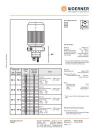
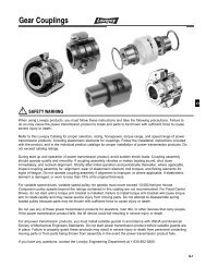
Couplings Reduce Vibration, Absorb Shock<br />
and Compensate for Misalignment.<br />
The Power of Torsional Damping<br />
The Lovejoy 1000 Series Flexible <strong>Grid</strong> Coupling reduces vibration by as<br />
much as 30%, and cushions shock loads to safeguard your driving and<br />
driven equipment. The flexible nature of the spring-like grid absorbs impact<br />
energy by spreading it out over time, thus reducing the magnitude of the<br />
peak loads. This is possible because of the progressive contact that occurs<br />
between the curved profile of the hub teeth and the flexible grid. Therefore,<br />
as the load increases, more of the tooth comes into contact with the grid,<br />
thus supplying superior protection and supreme performance.<br />
Lovejoy 1000 Series Flexible <strong>Grid</strong> Couplings are designed for versatility.<br />
Common hubs and grids are used within a given size range for both<br />
horizontal and vertical split cover models. <strong>Grid</strong> installation and replacement<br />
is a “snap” at only a fraction of the complete coupling cost.<br />
Benefits of the <strong>Grid</strong> Coupling include:<br />
Our 1000 Series Tapered <strong>Grid</strong> coupling is fully interchangeable with<br />
industry standards.<br />
Quick installation and easy maintenance reduces labor and downtime<br />
costs.<br />
Torsionally flexible and resilient - reduces vibration, plus cushions shock<br />
and impact loads.<br />
Versatile stock components can be used with either horizontal or<br />
vertical covers. Cover fasteners available in either Metric or Imperial<br />
sizes.<br />
High tensile, shot-peened alloy steel grids and precision machined hubs<br />
ensure superior performance and long life.<br />
HORIZONTALLY SPLIT COVER<br />
Ideal for limited space.<br />
Allows easy access to grid.<br />
Well-suited for reversing service.<br />
Manufactured from die-cast aluminum.<br />
Top Quality Manufacturing<br />
Made from a high tensile alloy steel, the grid spring is carefully formed to<br />
shape, then hardened and tempered under controlled conditions. Next, the<br />
grids are shot-peened, compressing the surface molecules and leaving a<br />
residually stressed surface. This process creates a stronger surface in<br />
compression.<br />
VERTICALLY SPLIT COVER<br />
Ideal for higher operating speeds.<br />
Manufactured from stamped steel.<br />
Any load applied on the coupling in operation must first surmount the<br />
compressive forces created by peening before the tensile stress reaches<br />
the grid. This provides a dramatic increase in rating over other coupling<br />
types, increases reserve strength for longer life and may permit selection<br />
of a smaller coupling, thus reducing cost.<br />
The Lovejoy <strong>Grid</strong> spring/hub tooth arrangement has been specifically<br />
designed for optimum performance and supreme reliability. Not only does<br />
the hub tooth profile permit progressive loading under torsional shock<br />
conditions, but unique root radii are incorporated to significantly improve<br />
the fatigue life of the teeth.<br />
GD-2<br />
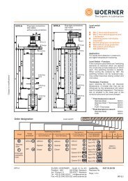
!<br />
WARNING<br />
You must refer to page iv for Important Safety Instructions and Precautions for<br />
the selection and use of these products. Failure to follow the instructions and<br />
precautions can result in severe injury or death.<br />
FULL SPACER DESIGN<br />
Ideal for pump applications because<br />
drop-out section allows for pump servicing.<br />
Used only with horizontally split cover.<br />
Available in sizes 1020-1090.
<strong>Grid</strong> <strong>Type</strong><br />
<strong>Grid</strong> Coupling Selection Process<br />
The selection process for determining the proper grid coupling size requires<br />
using the charts shown on the following pages. There are three<br />
components to be selected: two hubs and one cover. When the shaft size of<br />
the driver and driven of the application are of the same diameter, the hubs<br />
selected will be the same. When shaft diameters differ, hubs selected will<br />
differ accordingly.<br />
Information necessary before a grid coupling can be selected:<br />
HP (or KW) and RPM or Torque of driver<br />
Shaft sizes and type of fit of driver and driven equipment and<br />
corresponding keyways<br />
Shaft gap<br />
Physical space limitations<br />
Application description<br />
Environmental conditions (i.e. extreme temperature, corrosive<br />
conditions, space limitations)<br />
For applications with high peak loads or brake applications use the<br />
formulas given on page GD-4 or consult Application Engineering for<br />
assistance. The following information is required for high peak loads or<br />
brake applications:<br />
<br />
<br />
<br />
System peak torque and frequency<br />
Duty cycle<br />
Brake torque rating<br />
Selection Process<br />
List of Charts provided for Selection:<br />
Chart 1 - Service Factors (pgs. GD-5-6)<br />
Chart 2 - General Service Factors (pg. GD-7)<br />
Chart 3 - Coupling Torque and Horsepower Ratings (pg. GD-7)<br />
Formulas:<br />
Nominal Torque = in-lb = (HP x 63025)<br />
RPM<br />
Nm = (KW x 9550)<br />
RPM<br />
Design Torque = Nominal Torque x Service Factor<br />
Steps In Selecting A <strong>Grid</strong> Coupling<br />
GD<br />
Step 1: Determine the Nominal Torque of your application by using the<br />
following formula:<br />
Nominal Torque = in-lb = (HP x 63025)<br />
RPM<br />
Nm = (KW x 9550)<br />
RPM<br />
Step 2: Using the Service Factors Chart 1 (pgs. GD-5-6), select the<br />
service factor which best corresponds to your application. If you<br />
cannot locate a service factor for your application, choose an<br />
appropriate value from the General Service Factors Chart 2 (pg.<br />
GD-7).<br />
Step 3: Calculate the Design Torque of your application by multiplying the<br />
Nominal Torque calculated in Step 1 by the Service Factor<br />
determined in Step 2.<br />
Design Torque = Nominal Torque x Service Factor<br />
Step 4: Using the Coupling Torque and Horsepower Ratings Chart 3<br />
(pg. GD-7) scan down the torque rating to the first value that is<br />
greater than or equal to the Design Torque calculated in Step 3.<br />
Once this value is located, refer to the corresponding coupling size<br />
in the first column of the Coupling Torque and Horsepower Ratings<br />
Chart 3 (pg. GD-7).<br />
Refer to the maximum RPM value (pg. GD-7) for the torque<br />
capability to ensure that the application requirements are met. If<br />
the requirement is not satisfied at this point, a different cover style<br />
or another type of coupling may be required for the application.<br />
Please consult Lovejoy Application Engineering.<br />
Step 5: Compare the application driver/driven shaft sizes to the maximum<br />
bore size available on the coupling selected. If coupling bore size<br />
is not large enough for the shaft diameter, select the next largest<br />
coupling that will accommodate the driver/driven shaft diameters.<br />
Refer to Chart 3 (pg. GD-7).<br />
Step 6: Using the Item (UPC) Number Selection charts (pgs. GD-8-10),<br />
find the appropriate Bore and Keyway sizes required and locate<br />
the Lovejoy Item (UPC) number. Next locate the appropriate<br />
Lovejoy Item (UPC) number for the Cover/<strong>Grid</strong> Assembly Kit.<br />
GD-3
<strong>Grid</strong> <strong>Type</strong><br />
Selection Process<br />
Selection Example<br />
A coupling is needed to connect a 50 HP standard electric motor rated at<br />
1800 RPM to a rotary compressor. The shaft size of the electric motor<br />
(driver) is 1.75 inches and the compressor (driven) is 1.5 inches. The shaft<br />
connections are .75 inches long. There are no special environmental<br />
conditions.<br />
Step 1: Determine the Nominal Torque:<br />
Nominal Torque = in-lb = (HP x 63025)<br />
RPM<br />
in-lb = (50 x 63025)<br />
1800<br />
= 1750.69<br />
Step 2: Using the Service Factors Chart 1 (pgs. GD-5-6), select the<br />
service factor which best corresponds to your application. The<br />
Service Factor for an electric motor driving a rotary compressor is<br />
1.25. The value of 1.25 is found under the application category<br />
Compressor, Rotary, column: Electric Motor in Chart 1.<br />
Step 3: Calculate the Design Torque of your application :<br />
Design Torque = Nominal Torque x Service Factor<br />
= 1750.69 x 1.25<br />
= 2188.37 in-lb<br />
Step 5: Compare the application driver/driven shaft sizes to the maximum<br />
bore size available in the coupling selected (pg. GD-7). The<br />
electric motor (driver) of this application has a shaft size of 1.75<br />
inches and the compressor (driven) has a shaft size of 1.5 inches.<br />
The G1050 coupling has a maximum bore of 1.875 inches, so it<br />
can accommodate the driver/driven shaft sizes.<br />
Therefore, the proper coupling size for this application is a 1050<br />
coupling with a horizontal cover.<br />
Step 6: Using the Item (UPC) Number Selection charts (pgs. GD-8-10),<br />
locate the appropriate Lovejoy Item (UPC) numbers.<br />
Locate the <strong>Grid</strong> Coupling Inch Hubs selection chart (pg. GD-8)<br />
The first bore size to be located is for the 1.75 inch shaft on the<br />
electric motor. Scan down the Bore/Keyway column to the 1.75<br />
inch bore entry. Read across to the 1050 column to locate the<br />
Lovejoy Item (UPC) number of 05483.<br />
The second bore size to be located is for the 1.5 inch shaft on the<br />
compressor. Scan down the Bore/Keyway column to the 1.5 inch<br />
bore entry. Read across to the 1050 column to locate the Lovejoy<br />
Item (UPC) number of 05481.<br />
GD<br />
Step 4: Referencing the Coupling Torque and Horsepower Ratings Chart 3<br />
(pg. GD-7), use the Torque Rating column to determine the proper<br />
coupling size. Scanning down the Torque Rating column, the first<br />
entry to accommodate the Design Torque value of 2188.37 in-lb is<br />
size 1050 with a nominal torque rating of 3500 in-lb. The maximum<br />
RPM of 1800 on the electric motor of the application does not<br />
exceed the 4500 RPM maximum allowed for this size with the<br />
horizontal cover.<br />
Locate the <strong>Grid</strong> Coupling Accessory selection chart (pg. GD-10)<br />
The cover/grid assembly is selected by scanning accross the <strong>Grid</strong><br />
Coupling Size row to the 1050 entry. Read down to the Horizontal<br />
Cover/<strong>Grid</strong> Assembly-Inch row to locate the Lovejoy Item (UPC)<br />
number of 05352.<br />
Each of these item (UPC) numbers should be prefixed with the<br />
Lovejoy Item (UPC) number of 697904.<br />
Selecting A <strong>Grid</strong> Coupling For High Peak<br />
Loads Or Brake Applications<br />
Use this selection method in the following instances: 1) High Peak Loads<br />
2 ) Brake Applications (A brake is part of the system but it is not part of the<br />
actual coupling.)<br />
Step 1: Calculate the Design Peak Torque using one of the following<br />
equations:<br />
Non-Reversing High Peak Torque =<br />
in-lb = System Peak Torque<br />
Nm = System Peak Torque<br />
in-lb = (System Peak HP x 63025)<br />
RPM<br />
Nm = (System Peak KW x 9550)<br />
RPM<br />
Reversing High Peak Torque =<br />
in-lb = 2 x System Peak Torque<br />
Nm = 2 X System Peak Torque<br />
in-lb = (2 x System Peak HP x 63025)<br />
RPM<br />
Nm = (2 x System Peak KW x 9550)<br />
RPM<br />
Occasional Peak Torques (Reversing or Non-Reversing) =<br />
in-lb = 0.5 x System Peak Torque<br />
Nm = 0.5 x System Peak Torque<br />
in-lb = (0.5 x System Peak HP x 63025)<br />
RPM<br />
Nm = (0.5 x System Peak KW x 9550)<br />
RPM<br />
Step 2: If the application is a brake application and the torque rating of the<br />
brake exceeds the motor torque the brake torque needs to used<br />
with the application service factor selected in Chart 1 (pg. GD-6-<br />
7).<br />
Design Torque = Brake Torque Rating x Service Factor<br />
Step 3: Once the Design Torque has been determined go through steps 4<br />
through 6 of the selection process on page GD-4 to determine the<br />
proper coupling size.<br />
GD-4
<strong>Grid</strong> <strong>Type</strong><br />
Selection Data<br />
Service Factors—Industries Chart 1<br />
Service Factors<br />
Service Factors<br />
Service Factors<br />
Electric Motor w/<br />
Standard Torque<br />
Reciprocating<br />
Engines-4/5 Cylinder<br />
Reciprocating<br />
Engines-6 or more Cyl.<br />
Electric Motor w/<br />
Standard Torque<br />
Reciprocating<br />
Engines-4/5 Cylinder<br />
Reciprocating<br />
Engines-6 or more Cyl.<br />
Electric Motor w/<br />
Standard Torque<br />
Reciprocating<br />
Engines-4/5 Cylinder<br />
Reciprocating<br />
Engines-6 or more Cyl.<br />
Aggregate Processing, Cement,<br />
Mining Kilns;Tube, Rod and<br />
Ball Mills<br />
Dryer, Rotary, Hammermill<br />
or Hog,Tumbling Mill or Barrel,<br />
Direct or on L.S. Shaft of Reducer,<br />
with Final Drive of Single<br />
Helical or Herringbone Gears ....1.75 2.75 2.25<br />
Grizzly, Direct or on L.S. Shaft<br />
of Reducer, with Final Drive<br />
of Machined Spur Gears ............2.00 3.00 2.50<br />
Crushers, Ore or Stone................2.50 * *<br />
Brewing and Distilling<br />
Bottle and Can Filling Machines,<br />
Brew Kettle..................................1.00 2.00 1.50<br />
Cookers, Continuous Duty,<br />
Mash Tub ....................................1.25 2.25 1.75<br />
Lauter Tub ....................................1.50 2.50 2.00<br />
Scale Hopper, Frequent Peaks ....1.75 2.75 2.25<br />
Clay Working Industry<br />
Brick Press, Briquette Machine,<br />
Clay Working Machine,<br />
Plug Mill ......................................1.75 2.75 2.25<br />
Dredges<br />
Conveyors ....................................1.25 2.25 1.75<br />
Maneuvering Winch, Pumps<br />
(Uniform Load), Utility Winch......1.50 2.50 2.00<br />
Cable Reel, Screen Drive,<br />
Stacker........................................1.75 2.75 2.25<br />
Cutter Head, Jig Drive..................2.00 3.00 2.50<br />
Food Industry<br />
Bottling, Can Filling Machine........1.00 2.00 1.50<br />
Cereal Cooker ..............................1.25 2.25 1.75<br />
Beet Slicer, Dough Mixer,<br />
Meat Grinder ..............................1.75 2.75 2.25<br />
Lumber<br />
Rolls, Non-Reversing,<br />
Sawdust Conveyor......................1.25 2.25 1.75<br />
Band Resaw, Sorting Table ..........1.50 2.50 2.00<br />
Circular Resaw, Cut-off, Planer,<br />
Slab Conveyor, Trimmer..............1.75 2.75 2.25<br />
Edger, Head Rig, Hog, Log<br />
Haul, Rolls, Reversing ................2.00 3.00 2.50<br />
Gang Saw (Reciprocating) ..................Refer To Lovejoy<br />
Metal Rolling Mills 1<br />
Soaking Pit Cover Drives - Lift ....1.00 2.00 1.50<br />
Coilers (Up or Down) Cold<br />
Mills only, Cooling Beds, Mill<br />
Tables Hot Bed or<br />
Transfer, Non-Reversing ..............1.50 2.50 2.00<br />
Reel Drives, Slitters, Steel Mill<br />
only, Wire Drawing Machinery ....1.75 2.75 2.25<br />
Coilers (Up or Down) Hot Mills<br />
only, Coke Plants Door<br />
Opener, Drawbench, Furnace<br />
Pushers, Hot and Cold Saws,<br />
Ingot Cars, Mill Tables Runout,<br />
Non-Reversing, Non-Plugging,<br />
Screwdown, Seamless Tube<br />
Mills -Thrust Block, Tube<br />
Conveyor Rolls, Reeler, Kick<br />
Out, Soaking Pit Cover Drives<br />
- Travel, Straighteners,<br />
Unscramblers ..............................2.00 3.00 2.50<br />
Coke Plants Pusher Ram<br />
Drive, ........................................2.50 * *<br />
Coke Plants Pusher or Larry<br />
Car Traction Drive, Feed<br />
Rolls-Blooming Mills, Manipulators,<br />
Mill Tables Roughing<br />
Breakdown Mills, Runout,<br />
Reversing, Seamless Tube<br />
Mills Piercer, Sideguards............3.00 * *<br />
Cold Mills, Hot Mills, Merchant<br />
Mills, Rod Mills, Skelp Mills ..............Refer To Lovejoy<br />
Oil Industry<br />
Chiller ..........................................1.25 2.25 1.75<br />
Paraffin Filter Press......................1.50 2.50 2.00<br />
Oilwell Pumping (not over 150%<br />
Peak Torque), Rotary Kiln ..........2.00 3.00 2.50<br />
Paper Mills<br />
Bleachers, Coaters, Stock<br />
Pumps, Centrifugal Constant<br />
Speed ........................................1.00 2.00 2.50<br />
Converting Machine, Felt<br />
Stretcher, Stock Pumps,<br />
Centrifugal Frequent Speed<br />
Changes Under Load ................1.25 2.25 1.75<br />
Line Shaft, Reel, Rewinder,<br />
Winder, Stock Chest, Washer,<br />
Thickener ....................................1.50 2.50 2.00<br />
Beater, Pulper, Calender,<br />
Couch, Cylinder, Dryer, Pulp<br />
Grinder, Fourdrinier, Press,<br />
Suction Roll ................................1.75 2.75 2.25<br />
Barker Auxiliary, Hydraulic,<br />
Mechanical, Barking Drum L.S.<br />
Shaft of Reducer with Final<br />
Drive-Helical or Herringbone<br />
Gear, Cutter, Felt Whipper,<br />
Jordan, Log Haul ........................2.00 3.00 2.50<br />
Barking Drum L.S. Shaft of<br />
Reducer with Final Drive-<br />
Machined Spur Gear, Chipper....2.50 * *<br />
Barking Drum L.S. Shaft of<br />
Reducer with Final Drive-Cast<br />
Tooth Spur Gear ........................3.00 * *<br />
Rubber Industry<br />
Tire/Tube Press Opener (Peak<br />
Torque)........................................1.00 2.00 1.50<br />
Extruder, Mixing Mill, Refiner<br />
or Sheeter (Five or More in<br />
Line), Tuber, Strainer, Pelletizer,<br />
Warming Mill (Three or More<br />
in Line)........................................1.75 2.75 2.25<br />
Calender, Mixing Mill, Refiner<br />
or Sheeter (Three/Four in<br />
Line), Warming Mill (One/Two<br />
in Line)........................................2.00 3.00 2.50<br />
Cracker, Plasticator, Mixing<br />
Mill, Refiner or Sheeter<br />
(One/Two in line), Intensive<br />
or Banbury Mixer, Tire<br />
Building Machine, Washer ..........2.50 * *<br />
Sewage Disposal Equipment<br />
Bar Screen, Chemical Feeders,<br />
Collectors, Dewatering<br />
Screen, Grit Collector ................1.00 2.00 1.50<br />
Sugar Industry<br />
Mill Stands, Turbine Driven with<br />
all Helical or Herringbone<br />
Gears..........................................1.50 2.50 2.00<br />
Cane Carrier & Leveler, Electric<br />
Drive or Steam Engine Drive<br />
with Helical Herringbone, or<br />
Spur Gears with any Prime<br />
Mover..........................................1.75 2.75 2.25<br />
GD<br />
Notes: 1. For high peak load applications, please refer to selection process on page GD-4.<br />
2. * Indicates that Lovejoy Application Engineering should be consulted with specific requirements.<br />
Caution:<br />
Applications involving reciprocating engines and reciprocating driven devices are subject to critical rotational speeds which may damage the coupling and/or connected<br />
equipment. Contact Lovejoy Application Engineering with specific requirements.<br />
GD-5
<strong>Grid</strong> <strong>Type</strong><br />
Selection Data<br />
Service Factors—Industries and Applications<br />
Service Factors<br />
Service Factors<br />
Chart 1, cont.<br />
Service Factors<br />
Electric Motor w/<br />
Standard Torque<br />
GD<br />
Reciprocating<br />
Engines-4/5 Cylinder<br />
Reciprocating<br />
Engines-6 or more Cyl.<br />
Electric Motor w/<br />
Standard Torque<br />
Reciprocating<br />
Engines-4/5 Cylinder<br />
Reciprocating<br />
Engines-6 or more Cyl.<br />
Electric Motor w/<br />
Standard Torque<br />
Reciprocating<br />
Engines-4/5 Cylinder<br />
Reciprocating<br />
Engines-6 or more Cyl.<br />
Cane Knife & Crusher ..................2.00 3.00 2.50<br />
Textile Industry<br />
Batcher, Dyeing Machinery,<br />
Mangle, Napper, Soaper ............1.25 2.25 1.75<br />
Calender, Card Machine, Cloth<br />
Finishing Machine, Dry Can,<br />
Loom, Spinner, Tenter Frame,<br />
Winder ........................................1.50 2.50 2.00<br />
Knitting Machine ....................................Refer To Lovejoy<br />
Applications<br />
Aerator..............................................2.00 3.00 2.50<br />
Agitators<br />
Vertical/Horizontal Screw, Propeller,<br />
Paddle ..............................1.00 2.00 1.50<br />
Barge Haul Puller ............................1.50 2.50 2.00<br />
Blowers<br />
Centrifugal....................................1.00 2.00 1.50<br />
Lobe, Vane ..................................1.25 2.25 1.75<br />
Car Dumpers ..................................2.50 * *<br />
Car Pullers ......................................1.50 2.50 2.00<br />
Clarifier, Classifier ..........................1.00 2.00 1.50<br />
Compressors<br />
Centrifugal, Rotary, Screw............1.00 2.00 1.50<br />
Rotary, Lobe or Vane....................1.25 2.25 1.75<br />
Reciprocating with Flywheel and<br />
Gear between Compressor and<br />
Prime Mover 4 or More Cyl.<br />
Single/Double Acting ..................1.75 2.75 2.25<br />
Reciprocating with flywheel<br />
and Gear between Compressor<br />
and Prime Mover Cyl. Double<br />
Acting..........................................2.00 3.00 2.50<br />
Reciprocating with Flywheel and<br />
Gear between Compressor and<br />
Prime Mover 1/2 Cyl. Single/<br />
Double Acting and 3 cyl.<br />
Single Acting ..............................3.00 * *<br />
Reciprocating Direct Connected,<br />
Without Flywheels ................................Refer To Lovejoy<br />
Conveyors 2<br />
Apron, Assembly, Belt, Chain,<br />
Flight, Screw ..............................1.00 2.00 1.50<br />
Bucket ..........................................1.25 2.25 1.75<br />
Live Roll, Shaker,<br />
Reciprocating..............................3.00 * *<br />
Cranes, Hoist 1, 2<br />
Slope ............................................1.50 2.50 2.00<br />
Main or Skip Hoist, Bridge,<br />
Travel, Trolley 2 ............................1.75 2.75 2.25<br />
Dynamometer ..................................1.00 2.00 1.50<br />
Elevators 2<br />
Bucket, Centrifugal, Discharge,<br />
Gravity Discharge ........................1.25 2.25 1.75<br />
Freight or Passenger .......................NOT APPROVED<br />
Escalators............................................NOT APPROVED<br />
Exciter, Generator ..........................1.00 2.00 1.50<br />
Extruder, Plastic ..............................1.50 2.50 2.00<br />
Fans<br />
Centrifugal, Forced Draft Motor<br />
Driven thru Fluid or Electric Slip<br />
Clutch..........................................1.00 2.00 1.50<br />
Induced Draft with Damper Control<br />
or Blade Cleaner ..................1.25 2.25 1.75<br />
Forced Draft-Across the Line<br />
start, Gas Recirculating..............1.50 2.50 2.00<br />
Cooling Tower, Induced Draft<br />
without Controls..........................2.00 3.00 2.50<br />
Feeders<br />
Apron, Belt, Disc, Screw ..............1.00 2.00 1.50<br />
Reciprocating ..............................2.50 * *<br />
Generators<br />
Even Load ....................................1.00 2.00 1.50<br />
Hoist or Railway Service ..............1.50 2.50 2.00<br />
Welder Load ................................2.00 3.00 2.50<br />
Hammermill......................................1.75 2.75 2.25<br />
Laundrywasher or Tumbler ............2.00 3.00 2.50<br />
Line Shafts<br />
Any Processing Machinery ..........1.50 2.50 2.00<br />
Machine Tools<br />
Auxiliary, Traverse Drive ..............1.00 2.00 1.50<br />
Main Drive ....................................1.50 2.50 2.00<br />
Bending Roll, Notching Press,<br />
Punch Press, Planer, Plate<br />
Reversing....................................1.75 2.75 2.25<br />
Manlifts ................................................NOT APPROVED<br />
Metal Forming Machines<br />
Slitters ..........................................1.00 2.00 1.50<br />
Wire Winder, Coilers, Uncoilers....1.50 2.50 2.00<br />
Wire Drawing, Flattening..............1.75 2.75 2.25<br />
Draw Bench Carriage, Main<br />
Drive, Extruder, Forming<br />
Machine, Forming Mills ..............2.00 3.00 2.50<br />
Mixers (see Agitators)<br />
Muller............................................1.50 2.50 2.00<br />
Concrete ......................................1.75 2.75 2.25<br />
Printing Press..................................1.50 2.50 2.00<br />
Pug Mill ............................................1.75 2.75 2.25<br />
Pulverizers<br />
Roller ............................................1.50 2.50 2.00<br />
Hammermill, Hog ........................1.75 2.75 2.25<br />
Pumps<br />
Centrifugal Constant Speed ........1.00 2.00 1.50<br />
Centrifugal Frequent Speed<br />
Changes under Load, Descaling,<br />
w/ Accumulators, Gear, Rotary,<br />
Vane............................................1.25 2.25 1.75<br />
Reciprocating, 3 or more<br />
Cylinders ....................................1.50 2.50 2.00<br />
Reciprocating, 2 Cyl. Double<br />
Acting..........................................1.75 2.75 2.25<br />
Reciprocating, 2 Cyl. Single<br />
Acting..........................................2.00 3.00 2.50<br />
Reciprocating, 1 Cyl. Single/<br />
Double Acting ............................3.00 * *<br />
Screens<br />
Air Washing, Water ......................1.00 2.00 1.50<br />
Rotary Coal, Sand........................1.50 2.50 2.00<br />
Grizzly ..........................................2.00 3.00 2.50<br />
Vibrating ......................................2.50 * *<br />
Ski Tows, Lifts .....................................NOT APPROVED<br />
Steering Gear ..................................1.00 2.00 1.50<br />
Stoker ..............................................1.00 2.00 1.50<br />
Tumbling Barrel ..............................1.75 2.75 2.25<br />
Winch, Maneuvering<br />
Dredge, Marine ..........................1.50 2.50 2.00<br />
Windlass ..........................................1.50 2.50 2.00<br />
Woodworking Machinery ................1.00 2.00 1.50<br />
Work Lift Platforms.............................NOT APPROVED<br />
Notes: 1. For high peak load applications, please refer to selection process on page GD-4.<br />
2. If people are transported Lovejoy does not recommend and will not warranty the use of the coupling.<br />
3. * Indicates that Lovejoy Application Engineering should be consulted with specific requirements.<br />
Caution:<br />
GD-6<br />
Applications involving reciprocating engines and reciprocating driven devices are subject to critical rotational speeds which may damage the coupling and/or connected<br />
equipment. Contact Lovejoy Application Engineering with specific requirements.
<strong>Grid</strong> <strong>Type</strong><br />
General Service Factors Chart 2<br />
Typical Applications for Electric Motor<br />
Typical<br />
or Turbine Driven Equipment<br />
Service Factor<br />
Constant Torque such as Centrifugal<br />
1.0<br />
Pumps, Blowers, and Compressors.<br />
Continuous Duty with some torque<br />
variations including Printing Presses, 1.5<br />
Extruders, Forced Draft Fans.<br />
Light shock loads from Briquetting<br />
Machine, Rubber Calender, or 2.0<br />
Crane and Hoist<br />
Moderate shock loading as expected<br />
from a Car Dumper, Reciprocating 2.5<br />
Feeder, or Vibrating Screen.<br />
Heavy Shock load with some<br />
negative torques from Crushers, 3.0<br />
Manipulators and Braking Drum.<br />
Applications like Reciprocating<br />
Consult<br />
Compressors with frequent torque<br />
Lovejoy<br />
reversals which do not necessarily<br />
Application<br />
cause reverse rotations.<br />
Engineering<br />
Selection Data<br />
Torque Ratings Taper-Lock Bushing Hubs Chart 1<br />
Maximum Bore 1 Maximum Torque Rated Torque<br />
Taper-Lock Bushing Bushing Coupling<br />
Size Bushing inch in-lbs in-lbs<br />
1030 1108 1.125 1300.0 1200.0<br />
1040 1108 1.125 1300.0 2000.0<br />
1050 1215 1.250 3550.0 3500.0<br />
1060 1615 1.625 4300.0 5500.0<br />
1070 2012 2.000 7150.0 8000.0<br />
1080 2525 2.500 11300.0 16500.0<br />
1090 3030 3.000 24000.0 30000.0<br />
1100 3030 3.000 24000.0 50500.0<br />
1110 3535 3.500 44800.0 75000.0<br />
1120 4040 4.000 77300.0 110000.0<br />
Note:<br />
1. The maximum bore is with a standard keyway.<br />
Torque and Horsepower Ratings Chart 3<br />
Basic HP Ratings Horizontal Vertical<br />
@ Varying RPM Torque Ratings Maximum Bore Max RPM Max RPM<br />
Size 100 1200 1800 3600 in-lbs Nm inch mm x1000 x1000<br />
1020 0.67 8.04 12.06 24.12 422 48 1.125 27 4.500 6.000<br />
1030 1.88 22.56 33.84 67.68 1200 136 1.375 35 4.500 6.000<br />
1040 3.22 38.64 57.96 115.92 2000 226 1.625 44 4.500 6.000<br />
1050 5.49 65.88 98.82 197.64 3500 395 1.875 51 4.500 6.000<br />
1060 8.71 104.52 156.78 313.56 5500 621 2.125 57 4.350 6.000<br />
1070 12.73 152.76 229.14 458.28 8000 904 2.500 68 4.125 5.500<br />
1080 26.13 313.56 470.34 940.68 16500 1864 3.000 83 3.600 4.750<br />
1090 47.57 570.84 856.26 1712.52 30000 3390 3.500 95 3.600 4.000<br />
1100 80 960.00 1440.00 .....aa 50500 5706 4.000 108 2.440 3.250<br />
1110 119 1428.00 2142.00 .....aa 75000 8474 4.500 117 2.250 3.000<br />
1120 175.5 2106.00 3159.00 .....aa 110000 12428 5.000 137 2.025 2.700<br />
1130 253.3 3039.60 4559.40 .....aa 160000 18078 6.000 165 1.800 2.400<br />
1140 364.5 4374.00 6561.00 .....aa 230000 25987 7.000 184 1.650 2.200<br />
1150 509.58 6114.96 .....aa .....aa 320000 36300 8.000 200 1.500 .....a<br />
1160 724.14 8689.68 .....aa .....aa 457000 51600 9.000 228 1.350 .....a<br />
1170 952.11 11425.32 .....aa .....aa 600000 67800 10.000 254 1.225 .....a<br />
1180 1314.18 .....aa .....aa .....aa 830000 93600 11.000 280 1.100 .....a<br />
G5430 509.58 6114.96 9172.44 .....aa 320000 36300 8.250 210 .....a 2.400<br />
G5431 724.14 8689.68 .....aa .....aa 457000 51600 7.500 190 .....a 1.450<br />
G5433 952.11 11425.32 .....aa .....aa 600000 67800 8.438 215 .....a 1.300<br />
G5435 1314.18 15770.16 .....aa .....aa 830000 93600 9.250 235 .....a 1.200<br />
G5437 1756.71 .....aa .....aa .....aa 1100000 125000 10.438 265 .....a 1.100<br />
G5439 2386.98 .....aa .....aa .....aa 1500000 170000 11.563 295 .....a 0.980<br />
G5441 3178.17 .....aa .....aa .....aa 2000000 226000 12.750 325 .....a 0.860<br />
G5443 4291.2 .....aa .....aa .....aa 2700000 306000 16.313 415 .....a 0.740<br />
Notes: 1. The maximum bore for the G54 series includes a shallow keyway.<br />
2. Sizes 1020 through 1140 are tapered grid styles; sizes 1150 through G5443 are straight grid style.<br />
GD-7<br />
GD
<strong>Grid</strong> <strong>Type</strong><br />
Item Selection<br />
1000 Series Tapered <strong>Grid</strong> Hub Item (UPC) Numbers—Inch Chart 1<br />
When referencing the Lovejoy Item (UPC) number, include 697904 as a prefix to the number shown in the table below.<br />
Bore Keyway 1020 1030 1040 1050 1060 1070 1080 1090 1100 1110 1120 1130 1140<br />
SOLID 05231 05232 05233 05234 05235 05236 05237 05238 05239 05240 05241 05242 05243<br />
1 /2 1 /8 x 1 / 16 05458 ..... ..... ..... ..... ..... ..... ..... ..... ..... ..... ..... .....<br />
5 /8 3 /16 x 3 / 32 05459 05464 ..... ..... ..... ..... ..... ..... ..... ..... ..... ..... .....<br />
3 /4 3 /16 x 3 / 32 05460 05465 06140 ..... ..... ..... ..... ..... ..... ..... ..... ..... .....<br />
7 /8 3 /16 x 3 / 32 05461 05466 05471 06141 06142 ..... ..... ..... ..... ..... ..... ..... .....<br />
15 /16 1 /4 x 1 / 8 06100 06101 06103 06106 ..... ..... ..... ..... ..... ..... ..... ..... .....<br />
GD<br />
1 1 /4 x 1 / 8 05462 05467 05472 06107 06112 ..... ..... ..... ..... ..... ..... ..... .....<br />
1 1 / 8<br />
1 /4 x 1 / 8 05463 05468 05473 05478 06113 06144 07364 ..... ..... ..... ..... ..... .....<br />
1 3 / 16<br />
1 /4 x 1 / 8 ..... 06102 06104 06108 06114 ..... ..... ..... ..... ..... ..... ..... .....<br />
1 1 / 4<br />
1 /4 x 1 / 8 ..... 05469 05474 05479 06115 06145 06148 ..... ..... ..... ..... ..... .....<br />
1 3 / 8<br />
5 /16 x 5 / 32 ..... 05470 05475 05480 05485 06119 06149 ..... ..... ..... ..... ..... .....<br />
1 7 / 16<br />
3 /8 x 3 / 16 ..... ..... 06105 06109 06116 06120 ..... ..... ..... ..... ..... ..... .....<br />
1 1 / 2<br />
3 /8 x 3 / 16 ..... ..... 05476 05481 05486 06121 ..... ..... ..... ..... ..... ..... .....<br />
1 5 / 8<br />
3 /8 x 3 / 16 ..... ..... 05477 05482 05487 05492 06150 ..... ..... ..... ..... ..... .....<br />
1 11 / 16<br />
3 /8 x 3 / 16 ..... ..... ..... 06110 06117 06122 ..... ..... ..... ..... ..... ..... .....<br />
1 3 / 4<br />
3 /8 x 3 / 16 ..... ..... ..... 05483 05488 05493 06124 ..... ..... ..... ..... ..... .....<br />
1 13 / 16<br />
1 /2 x 1 / 4 ..... ..... ..... 06111 06118 06123 06125 ..... ..... ..... ..... ..... .....<br />
1 7 / 8<br />
1 /2 x 1 / 4 ..... ..... ..... 05484 05489 05494 06126 06154 ..... ..... ..... ..... .....<br />
1 15 /16<br />
1 /2 x 1 / 4 ..... ..... ..... ..... 06143 06146 06151 ..... ..... ..... ..... ..... .....<br />
2 1 /2 x 1 / 4 ..... ..... ..... ..... 05490 05495 05500 06155 ..... ..... ..... ..... .....<br />
2 1 / 8<br />
1 /2 x 1 / 4 ..... ..... ..... ..... 05491 05496 05501 06127 ..... ..... ..... ..... .....<br />
2 3 / 16<br />
1 /2 x 1 / 4 ..... ..... ..... ..... ..... 06147 06152 06156 ..... ..... ..... ..... .....<br />
2 1 / 4<br />
1 /2 x 1 / 4 ..... ..... ..... ..... ..... 05497 05502 06128 ..... ..... ..... ..... .....<br />
2 3 / 8<br />
5 /8 x 5 / 16 ..... ..... ..... ..... ..... 05498 05503 06129 ..... ..... ..... ..... .....<br />
2 1 / 2<br />
5 /8 x 5 / 16 ..... ..... ..... ..... ..... 05499 05504 05509 05519 ..... ..... ..... .....<br />
2 5 / 8<br />
5 /8 x 5 / 16 ..... ..... ..... ..... ..... ..... 05505 05510 05520 ..... ..... ..... .....<br />
2 3 / 4<br />
5 /8 x 5 / 16 ..... ..... ..... ..... ..... ..... 05506 05511 05521 ..... ..... ..... .....<br />
2 7 / 8<br />
3 /4 x 3 / 8 ..... ..... ..... ..... ..... ..... 05507 05512 05522 ..... ..... ..... .....<br />
2 15 /16<br />
3 /4 x 3 / 8 ..... ..... ..... ..... ..... ..... 06153 06157 ..... ..... ..... ..... .....<br />
3 3 /4 x 3 / 8 ..... ..... ..... ..... ..... ..... 05508 05513 05523 05532 05542 ..... .....<br />
3 1 / 8<br />
3 /4 x 3 / 8 ..... ..... ..... ..... ..... ..... ..... 05514 05524 05533 05543 ..... .....<br />
3 1 / 4<br />
3 /4 x 3 / 8 ..... ..... ..... ..... ..... ..... ..... 05515 05525 05534 05544 ..... .....<br />
3 3 / 8<br />
7 /8 x 7 / 16 ..... ..... ..... ..... ..... ..... ..... 05516 05526 05535 05545 ..... .....<br />
3 7 / 16<br />
7 /8 x 7 / 16 ..... ..... ..... ..... ..... ..... ..... 06158 ..... ..... ..... ..... .....<br />
3 1 / 2<br />
7 /8 x 7 / 16 ..... ..... ..... ..... ..... ..... ..... 05517 05527 05536 05546 05553 .....<br />
3 5 / 8<br />
7 /8 x 7 / 16 ..... ..... ..... ..... ..... ..... ..... ..... 05528 05537 05547 05554 .....<br />
3 3 / 4<br />
7 /8 x 7 / 16 ..... ..... ..... ..... ..... ..... ..... ..... 05529 05538 05548 05555 .....<br />
3 7 / 8 1" x 1 / 2 ..... ..... ..... ..... ..... ..... ..... ..... 05530 05539 05549 05556 05562<br />
4 1" x 1 / 2 ..... ..... ..... ..... ..... ..... ..... ..... 05531 05540 05550 05557 05563<br />
4 1 / 2 1" x 1 / 2 ..... ..... ..... ..... ..... ..... ..... ..... ..... 05541 05551 05558 05564<br />
5 1 1 / 4 x 5 / 8 ..... ..... ..... ..... ..... ..... ..... ..... ..... ..... 05552 05559 05565<br />
5 1 / 2 1 1 / 4 x 5 / 8 ..... ..... ..... ..... ..... ..... ..... ..... ..... ..... ..... 05560 05566<br />
6 1 1 / 2 x 3 / 4 ..... ..... ..... ..... ..... ..... ..... ..... ..... ..... ..... 05561 05567<br />
6 1 / 2 1 1 / 2 x 3 / 4 ..... ..... ..... ..... ..... ..... ..... ..... ..... ..... ..... ..... 05568<br />
7 1 1 / 2 x 3 / 4 ..... ..... ..... ..... ..... ..... ..... ..... ..... ..... ..... ..... 05569<br />
Notes: 1. 1020-1090 hubs are provided with a Clearance Fit bore and 2 Set Screws at 90º.<br />
2. 1100-1140 hubs are provided with an Interference Fit bore and no Set Screws.<br />
3. A complete grid coupling consists of two hubs and one Cover/<strong>Grid</strong> Assembly.<br />
GD-8
<strong>Grid</strong> <strong>Type</strong><br />
Item Selection<br />
1000 Series Tapered <strong>Grid</strong> Hub Item (UPC) Numbers—Metric Chart 2<br />
When referencing the Lovejoy Item (UPC) number, include 697904 as a prefix to the number shown in the table below.<br />
Bore Keyway 1020 1030 1040 1050 1060 1070 1080 1090<br />
14 5 x 2.3 05780 ..... ..... ..... ..... ..... ..... .....<br />
15 5 x 2.3 05781 ..... ..... ..... ..... ..... ..... .....<br />
16 5 x 2.3 05782 ..... ..... ..... ..... ..... ..... .....<br />
19 6 x 2.8 05783 05788 ..... ..... ..... ..... ..... .....<br />
20 6 x 2.8 05784 05789 ..... ..... ..... ..... ..... .....<br />
22 6 x 2.8 05785 05790 ..... ..... ..... ..... ..... .....<br />
24 8 x 3.3 05786 05791 05797 ..... ..... ..... ..... .....<br />
25 8 x 3.3 05787 05792 05798 ..... ..... ..... ..... .....<br />
28 8 x 3.3 ..... 05793 05799 05805 ..... ..... ..... .....<br />
30 8 x 3.3 ..... 05794 05800 05806 ..... ..... ..... .....<br />
32 10 x 3.3 ..... 05795 05801 05807 ..... ..... ..... .....<br />
35 10 x 3.3 ..... 05796 05802 05808 05812 05817 ..... .....<br />
38 10 x 3.3 ..... ..... 05803 05809 05813 05818 05823 .....<br />
42 12 x 3.3 ..... ...... 05804 05810 05814 05819 05824 05830<br />
48 14 x 3.8 ..... ..... ..... 05811 05815 05820 05825 05831<br />
55 16 x 4.3 ..... ..... ..... ..... 05816 05821 05826 05832<br />
60 18 x 4.4 ..... ..... ..... ..... ..... 05822 05827 05833<br />
70 20 x 4.9 ..... ..... ..... ..... ..... ..... 05828 05834<br />
80 22 x 5.4 ..... ..... ..... ..... ..... ..... 05829 05835<br />
85 22 x 5.4 ..... ..... ..... ..... ..... ..... ..... 05836<br />
95 25 x 5.4 ..... ..... ..... ..... ..... ..... ..... 05837<br />
Notes: 1. 1020-1090 hubs are provided with a Clearance Fit bore and 2 Set Screws at 90º.<br />
2. A complete grid coupling consists of two hubs and one Cover/<strong>Grid</strong> Assembly.<br />
GD<br />
1000 Series Taper-Lock <strong>Grid</strong> Hub Item (UPC) Numbers Chart 3<br />
When referencing the Lovejoy Item (UPC) Number, include 697904 as a prefix to the number shown in the table below.<br />
Taper-Lock<br />
Hub 1030 1040 1050 1060 1070 1080 1090 1100 1110 1120<br />
UNC Thread 06841 06842 06843 06844 06845 06846 06847 06848 06849 06850<br />
BSW Thread 06851 06852 06853 06854 06855 06856 06857 06858 06859 06860<br />
GD-9
<strong>Grid</strong> <strong>Type</strong><br />
Item Selection<br />
Item (UPC) Numbers—1000 Series Tapered <strong>Grid</strong> Component Parts Chart 3<br />
When referencing the Lovejoy Item (UPC) number, include 697904 as a prefix to the number shown in the table below. A complete <strong>Grid</strong> Coupling consists of two<br />
hubs and one Cover/<strong>Grid</strong> Assembly.<br />
GD<br />
Sizes 1020 1030 1040 1050 1060 1070 1080 1090 1100 1110 1120 1130 1140<br />
<strong>Grid</strong> Only 05244 05245 05246 05247 05248 05249 05250 05251 05252 05253 05254 05255 05256<br />
Horizontal Design:<br />
Cover/<strong>Grid</strong> Assembly-Metric 05366 05367 05368 05369 05370 05371 05372 05373 05374 05375 05376 05377 05378<br />
Cover/<strong>Grid</strong> Assembly-Inch 05349 05350 05351 05352 05353 05354 05355 05356 05357 05358 05359 05360 05361<br />
Cover Set - Metric 05290 05291 05292 05293 05294 05295 05296 05297 05298 05299 05300 05301 05302<br />
Cover Set - Inch 05273 05274 05275 05276 05277 05278 05279 05280 05281 05282 05283 05284 05285<br />
Seal Kit 05176 05177 05178 05179 05180 05181 05182 05183 05184 05185 05186 05187 05188<br />
Cover Hardware - Metric 05210 05210 05210 05211 05211 05212 05212 05212 05213 05213 05214 05214 05214<br />
Cover Hardware - Inch 05433 05433 05433 05434 05434 05435 05435 05435 05436 05436 05437 05437 05437<br />
Vertical Design:<br />
Cover/<strong>Grid</strong> Assembly-Metric 05400 05401 05402 05403 05404 05405 05406 05407 05408 05409 05410 05411 05412<br />
Cover/<strong>Grid</strong> Assembly-Inch 05383 05384 05385 05386 05387 05388 05389 05390 05391 05392 05393 05394 05395<br />
Cover Set - Metric 05328 05329 05330 05331 05332 05333 05334 05335 05336 05337 05338 05339 05340<br />
Cover Set - Inch 05307 05308 05309 05310 05311 05312 05313 05314 05315 05316 05317 05318 05319<br />
Seal Kit 05189 05190 05191 05192 05193 05194 05195 05196 05197 05198 05199 05200 05201<br />
Cover Hardware - Metric 05215 05216 05216 05217 05217 05217 05218 05218 05219 05219 05220 05221 05222<br />
Cover Hardware - Inch 05442 05443 05443 05444 05444 05444 05445 05445 05446 05446 05447 05448 05449<br />
Notes: 1. “Cover/<strong>Grid</strong> Assembly” includes ALL components of the coupling, other than the hubs. The terms “metric” and “inch” refer to hardware.<br />
2. “Cover Set” includes all of the above items except the <strong>Grid</strong> spring.<br />
3. “Seal Kit” contains rubber seals, gasket(s) and lube plugs.<br />
4. “Cover Hardware” includes the fasteners that hold the cover together.<br />
5. Grease packets are included with all Cover Sets and Cover/<strong>Grid</strong> assemblies thru size 1090.<br />
Item (UPC) Numbers—Straight <strong>Grid</strong> Component Parts Chart 4<br />
When referencing the Lovejoy Item (UPC) number, include 697904 as a prefix to the number shown in the table below. A complete <strong>Grid</strong> Coupling consists<br />
of two hubs and one Cover/<strong>Grid</strong> Assembly.<br />
Sizes 1150 1160 1170 1180 G5430 G5431 G5433 G5435 G5437 G5439 G5441 G5443<br />
Horizontal Design:<br />
Vertical Design:<br />
Hub 73mm RSB 05587 ..... ..... ..... 05265 ..... ..... ..... ..... ..... ..... .....<br />
Hub 100mm RSB ..... 05589 05591 ..... ..... ..... ..... ..... ..... ..... ..... .....<br />
Hub Free 100mm RSB ..... ..... ..... ..... ..... 05266 05267 ..... ..... ..... ..... .....<br />
Hub Fixed 100mm RSB ..... ..... ..... ..... ..... 06764 06765 ..... ..... ..... ..... .....<br />
Hub 125mm RSB ..... ..... ..... 05593 ..... ..... ..... ..... ..... ..... ..... .....<br />
Hub Free 125mm RSB ..... ..... ..... ..... ..... ..... ..... 05268 05269 ..... ..... .....<br />
Hub Fixed 125mm RSB ..... ..... ..... ..... ..... ..... ..... 06766 06767 ..... ..... .....<br />
Hub Free 150mm RSB ..... ..... ..... ..... ..... ..... ..... ..... ..... 05270 05271 .....<br />
Hub Fixed 150mm RSB ..... ..... ..... ..... ..... ..... ..... ..... ..... 06768 06769 .....<br />
Hub Free 175mm RSB ..... ..... ..... ..... ..... ..... ..... ..... ..... ..... ..... 05272<br />
Hub Fixed 175mm RSB ..... ..... ..... ..... ..... ..... ..... ..... ..... ..... ..... 06770<br />
<strong>Grid</strong> Only 05257 05258 05259 05260 05257 05258 05259 05260 05261 05262 05263 05264<br />
Cover/<strong>Grid</strong> Assembly-Metric 05379 05380 05381 05382 05413 05414 05415 05416 05417 05418 05419 05420<br />
Cover/<strong>Grid</strong> Assembly-Inch 05362 05363 05364 05365 .... ..... ..... ..... ..... ..... ..... .....<br />
Cover Set - Metric 05303 05304 05305 05306 05341 05342 05343 05344 05345 05346 05347 05348<br />
Cover Set - Inch 05286 05287 05288 05289 ..... ..... ..... ..... ..... ..... ..... .....<br />
Seal Kit 05425 05426 05427 05428 05202 05203 05204 05205 05206 05207 05208 05209<br />
Cover Hardware - Metric 05429 05429 05430 05430 05223 05224 05225 05226 05227 05228 05229 05230<br />
Cover Hardware - Inch 05438 05438 05439 05439 ..... ..... ..... ..... ..... ..... ..... .....<br />
Notes: 1. “Cover/<strong>Grid</strong> Assembly” includes ALL components of the coupling, other than the hubs. The terms “metric” and “inch” refer to hardware.<br />
2. “Cover Set” includes all of the above items except the <strong>Grid</strong> spring.<br />
3. “Seal Kit” contains rubber seals, gasket(s) and lube plugs.<br />
4. “Cover Hardware” includes the fasteners that hold the cover together.<br />
5. Grease packets are included with all Cover Sets and Cover/<strong>Grid</strong> assemblies thru size 1090.<br />
GD-10
<strong>Grid</strong> <strong>Type</strong><br />
Performance Data<br />
Interchange Chart<br />
Horizontal<br />
Vertical<br />
Split Cover<br />
Split Cover<br />
Lovejoy Falk Morse/Browning Dodge Kop-Flex Falk Morse/Browning Dodge Kop-Flex<br />
Size Steelflex <strong>Grid</strong>-Flex <strong>Grid</strong>-Lign Kop-<strong>Grid</strong> Steelflex <strong>Grid</strong>-Flex <strong>Grid</strong>-Lign Kop-<strong>Grid</strong><br />
1020 1020T10 GF2020H 1020T10 1020H 1020T20 GF2020V 1020T20 1020V<br />
1030 1030T10 GF2030H 1030T10 1030H 1030T20 GF2030V 1030T20 1030V<br />
1040 1040T10 GF2040H 1040T10 1040H 1040T20 GF2040V 1040T20 1040V<br />
1050 1050T10 GF2050H 1050T10 1050H 1050T20 GF2050V 1050T20 1050V<br />
1060 1060T10 GF2060H 1060T10 1060H 1060T20 GF2060V 1060T20 1060V<br />
1070 1070T10 GF2070H 1070T10 1070H 1070T20 GF2070V 1070T20 1070V<br />
1080 1080T10 GF2080H 1080T10 1080H 1080T20 GF2080V 1080T20 1080V<br />
1090 1090T10 GF2090H 1090T10 1090H 1090T20 GF2090V 1090T20 1090V<br />
1100 1100T10 GF2100H 1100T10 1100H 1100T20 GF2100V 1100T20 1100V<br />
1110 1110T10 GF2110H 1110T10 1110H 1110T20 GF2110V 1110T20 1110V<br />
1120 1120T10 GF2120H 1120T10 1120H 1120T20 GF2120V 1120T20 1120V<br />
1130 1130T10 GF2130H 1130T10 1130H 1130T20 GF2130V 1130T20 1130V<br />
1140 1140T10 GF2140H 1140T10 1140H 1140T20 GF2140V 1140T20 1140V<br />
1150 1150T10 ..... ..... ..... ..... ..... ..... .....<br />
1160 1160T10 ..... ..... ..... ..... ..... ..... .....<br />
1170 1170T10 ..... ..... ..... ..... ..... ..... .....<br />
1180 1180T10 ..... ..... ..... ..... ..... ..... .....<br />
G5430 ..... ..... ..... ..... 1150T20 ..... ..... .....<br />
G5431 ..... ..... ..... ..... 1160T20 ..... ..... .....<br />
G5433 ..... ..... ..... ..... 1170T20 ..... ..... .....<br />
Note: 1020 to 1140 interchanges with Falk. 1150 and above are not direct interchanges with Falk.<br />
Torque and Horsepower Ratings<br />
Basic HP Ratings Horizontal Vertical<br />
@ Varying RPM Torque Ratings Maximum Bore Max RPM Max RPM<br />
Size 100 1200 1800 3600 in-lbs Nm inch mm x1000 x1000<br />
1020 0.67 8.04 12.06 24.12 422 48 1.125 27 4.500 6.000<br />
1030 1.88 22.56 33.84 67.68 1200 136 1.375 35 4.500 6.000<br />
1040 3.22 38.64 57.96 115.92 2000 226 1.625 44 4.500 6.000<br />
1050 5.49 65.88 98.82 197.64 3500 395 1.875 51 4.500 6.000<br />
1060 8.71 104.52 156.78 313.56 5500 621 2.125 57 4.350 6.000<br />
1070 12.73 152.76 229.14 458.28 8000 904 2.500 68 4.125 5.500<br />
1080 26.13 313.56 470.34 940.68 16500 1864 3.000 83 3.600 4.750<br />
1090 47.57 570.84 856.26 1712.52 30000 3390 3.500 95 3.600 4.000<br />
1100 80.00 960.00 1440.00 .....aa 50500 5706 4.000 108 2.440 3.250<br />
1110 119.00 1428.00 2142.00 .....aa 75000 8474 4.500 117 2.250 3.000<br />
1120 175.50 2106.00 3159.00 .....aa 110000 12428 5.000 137 2.025 2.700<br />
1130 253.30 3039.60 4559.40 .....aa 160000 18078 6.000 165 1.800 2.400<br />
1140 364.50 4374.00 6561.00 .....aa 230000 25987 7.000 184 1.650 2.200<br />
1150 509.58 6114.96 .....aa .....aa 320000 36300 8.000 200 1.500 .....a<br />
1160 724.14 8689.68 .....aa .....aa 457000 51600 9.000 228 1.350 .....a<br />
1170 952.11 11425.32 .....aa .....aa 600000 67800 10.000 254 1.225 .....a<br />
1180 1314.18 .....aa .....aa .....aa 830000 93600 11.000 280 1.100 .....a<br />
G5430 509.58 6114.96 9172.44 .....aa 320000 36300 8.250 210 .....a 2.400<br />
G5431 724.14 8689.68 .....aa .....aa 457000 51600 7.500 190 .....a 1.450<br />
G5433 952.11 11425.32 .....aa .....aa 600000 67800 8.438 215 .....a 1.300<br />
G5435 1314.18 15770.16 .....aa .....aa 830000 93600 9.250 235 .....a 1.200<br />
G5437 1756.71 .....aa .....aa .....aa 1100000 125000 10.438 265 .....a 1.100<br />
G5439 2386.98 .....aa .....aa .....aa 1500000 170000 11.563 295 .....a 0.980<br />
G5441 3178.17 .....aa .....aa .....aa 2000000 226000 12.750 325 .....a 0.860<br />
G5443 4291.2 .....aa .....aa .....aa 2700000 306000 16.313 415 .....a 0.740<br />
Note: The maximum bore for 5430 to G5443 includes a shallow keyway.<br />
GD-11<br />
GD
<strong>Grid</strong> <strong>Type</strong><br />
Performance Data<br />
GD<br />
Misalignment Capacity<br />
Max. Installation Operating Normal<br />
Misalignment Misalignment Gap<br />
Coupling Parallel Angular Parallel Angular ±10 %<br />
Size P X-Y P X-Y G<br />
1020 0.006 0.003 0.012 0.010 0.125<br />
1030 0.006 0.003 0.012 0.012 0.125<br />
1040 0.006 0.003 0.012 0.013 0.125<br />
1050 0.008 0.004 0.016 0.016 0.125<br />
1060 0.008 0.005 0.016 0.018 0.125<br />
1070 0.008 0.005 0.016 0.020 0.125<br />
1080 0.008 0.006 0.016 0.024 0.125<br />
1090 0.008 0.007 0.016 0.028 0.125<br />
1100 0.010 0.008 0.020 0.033 0.188<br />
1110 0.010 0.009 0.020 0.036 0.188<br />
1120 0.011 0.010 0.022 0.040 0.250<br />
1130 0.011 0.012 0.022 0.047 0.250<br />
1140 0.011 0.013 0.022 0.053 0.250<br />
1150 0.010 0.014 ..... ..... 0.248<br />
1160 0.010 0.014 ..... ..... 0.248<br />
1170 0.010 0.014 ..... ..... 0.248<br />
1180 0.010 0.014 ..... ..... 0.248<br />
G5430 0.010 0.014 ..... ..... 0.098<br />
G5431 0.010 0.014 ..... ..... 0.118<br />
G5433 0.010 0.014 ..... ..... 0.118<br />
G5435 0.010 0.014 ..... ..... 0.118<br />
G5437 0.010 0.014 ..... ..... 0.118<br />
G5439 0.010 0.014 ..... ..... 0.118<br />
G5441 0.014 0.020 ..... ..... 0.236<br />
G5443 0.014 0.020 ..... ..... 0.236<br />
Note: Misalignment ratings pertain to both standard and spacer grid couplings.<br />
ANGULAR MISALIGNMENT<br />
PARALLEL MISALIGNMENT<br />
NORMAL GAP<br />
Misalignment Capacity:<br />
Parallel: The movement of the grid in the hub<br />
grooves accommodates parallel misalignment<br />
and still permits full functioning of the gridgroove<br />
action in damping out shock and<br />
vibration.<br />
Angular: Under angular misalignment, the<br />
grid-groove design permits a rocking and<br />
sliding action of the grid and hubs without<br />
any loss of power through the resilient grid.<br />
Axial: End float is permitted for both driving<br />
and driven members because the grid slides<br />
freely in the grooves.<br />
GD-12
<strong>Grid</strong> <strong>Type</strong><br />
Dimensional Data<br />
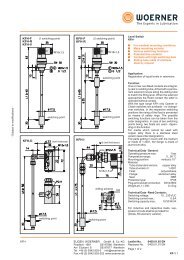
Horizontal Style <strong>Grid</strong> Couplings<br />
<strong>Grid</strong> couplings with horizontally split covers are ideal for limited space<br />
applications. The cover design allows for easy access to the grid. In<br />
addition, this cover style is well-suited for reversing service applications.<br />
1150<br />
1020-1140<br />
Dimensional Data—Inch<br />
1160-1180<br />
GD<br />
Length Set Moment<br />
Outer Overall Thru Hub Screw Weight of Inertia<br />
Bore Dia. Length Gap Bore Dia. Length Location Size lbs WR 2 lb-in 2<br />
Size Min. Max. OD OAL G LTB HD L SL T Solid Solid<br />
1020 0.500 1.125 4.00 3.88 0.13 1.88 1.56 2.63 0.50 #8-32 4.2 4.830<br />
1030 0.500 1.375 4.38 3.88 0.13 1.88 1.94 2.69 0.31 #8-32 5.7 7.610<br />
1040 0.500 1.625 4.63 4.13 0.13 2.00 2.25 2.75 0.44 #10-24 7.4 11.190<br />
1050 0.500 1.875 5.44 4.88 0.13 2.38 2.63 3.13 0.62 #10-24 12.0 24.850<br />
1060 0.750 2.125 5.94 5.13 0.13 2.50 3.00 3.63 0.44 #10-24 16.0 40.660<br />
1070 0.750 2.500 6.38 6.13 0.13 3.00 3.44 3.75 0.88 1 /4 -20 23.0 63.180<br />
1080 1.000 3.000 7.63 7.13 0.13 3.50 4.13 4.56 0.94 1 /4 -20 39.0 154.000<br />
1090 1.000 3.500 8.38 7.88 0.13 3.88 4.88 4.81 1.03 5 /16 -18 56.0 269.000<br />
1100 1.625 4.000 9.88 9.69 0.19 4.75 5.59 6.13 ..... ..... 93.0 609.000<br />
1110 1.625 4.500 10.63 10.19 0.19 5.00 6.31 6.36 ..... ..... 120.0 923.000<br />
1120 2.375 5.000 12.13 12.00 0.25 5.88 7.06 7.55 ..... ..... 179.0 1755.000<br />
1130 2.625 6.000 13.63 13.00 0.25 6.38 8.56 7.69 ..... ..... 266.0 3378.000<br />
1140 2.625 7.000 15.13 14.75 0.25 7.25 10.00 7.92 ..... ..... 392.0 6306.000<br />
1150 3.000 8.000 17.91 14.65 0.25 7.20 11.54 8.42 ..... ..... 523.0 .....A<br />
1160 4.188 9.000 20.47 15.85 0.25 7.80 11.97 10.43 ..... ..... 720.0 .....A<br />
1170 4.188 10.000 23.03 17.25 0.25 8.50 13.98 11.85 ..... ..... 1022.5 .....A<br />
1180 5.125 11.000 25.00 19.07 0.25 9.41 15.47 12.24 ..... ..... 1341.7 .....A<br />
Notes:<br />
1. Maximum bores are less than shown above when an Interference Fit and Set Screw are required, refer to Lovejoy Application<br />
Engineering. Sizes 1020 through 1090 are Clearance Fit with 2 Set Screws at 90º. Sizes 1100 and larger are an Interference Fit with no<br />
Set Screw.<br />
2. Based on application data, larger bores may be possible - contact Lovejoy Application Engineering.<br />
3. See pages GD-11 & GD-12 for Performance Data.<br />
GD-13
<strong>Grid</strong> <strong>Type</strong><br />
Dimensional Data<br />
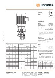
Vertical Style <strong>Grid</strong> Couplings<br />
Vertically split cover design grid couplings are ideal for applications with<br />
higher operating speeds. Sizes G1020-1140 and G5430 are stamped steel,<br />
sizes G5431 and above are cast iron. This cover style offers superior<br />
protection and supreme performance.<br />
1050V<br />
1020-1140<br />
GD<br />
Dimensional Data—Inch<br />
Length Set Moment<br />
Outer Overall Thru Hub Flange Flange Screw Weight of Inertia<br />
Bore Dia. Length Gap Bore Dia. Dia. Length Length Max Location Size lbs WR 2 lb.in 2<br />
Size Min. Max. OD OAL G LTB HD FD L FL R SL T Solid Solid<br />
1020 0.500 1.125 4.38 3.88 0.13 1.88 1.56 2.50 0.96 0.38 1.88 0.50 #8-32 4.3 5.320<br />
1030 0.500 1.375 4.75 3.88 0.13 1.88 1.94 2.88 1.00 0.38 1.88 0.31 #8-32 5.7 7.990<br />
1040 0.500 1.625 5.06 4.13 0.13 2.00 2.25 3.25 1.03 0.38 2.00 0.44 #10-24 7.4 11.990<br />
1050 0.500 1.875 5.81 4.88 0.13 2.38 2.63 3.88 1.24 0.47 2.38 0.62 #10-24 12.0 25.760<br />
1060 0.750 2.125 6.38 5.13 0.13 2.50 3.00 4.38 1.27 0.50 2.50 0.44 #10-24 16.0 41.160<br />
1070 0.750 2.500 6.81 6.13 0.13 3.00 3.44 4.88 1.33 0.50 2.63 0.88 1 /4 -20 23.0 61.680<br />
1080 1.000 3.000 7.88 7.13 0.13 3.50 4.13 5.88 1.74 0.50 3.50 0.94 1 /4 -20 39.0 148.000<br />
1090 1.000 3.500 9.13 7.88 0.13 3.88 4.88 6.63 1.86 0.50 3.75 1.03 5 /16 -18 56.0 272.000<br />
1100 1.625 4.000 10.50 9.69 0.19 4.75 5.59 7.75 2.38 0.63 4.75 ..... ..... 93.0 608.000<br />
1110 1.625 4.500 11.25 10.19 0.19 5.00 6.31 8.50 2.50 0.63 4.88 ..... ..... 120.0 930.000<br />
1120 2.375 5.000 12.56 12.00 0.25 5.88 7.06 9.63 2.94 0.68 5.63 ..... ..... 180.0 1611.000<br />
1130 2.625 6.000 14.88 13.00 0.25 6.38 8.56 11.13 3.00 0.82 5.75 ..... ..... 270.0 3568.000<br />
1140 2.625 7.000 16.38 14.75 0.25 7.50 10.00 12.63 3.13 0.82 6.13 ..... ..... 397.0 6431.000<br />
G5430 3.000 8.250 16.73 13.88 0.10 6.89 11.54 ..... ..... ..... 5.91 ..... ..... 511.6 9740.568<br />
G5431 4.188 7.438 20.87 15.87 0.12 7.87 10.43 ..... ..... ..... 7.72 ..... ..... 632.8 20472.282<br />
G5433 4.188 8.438 23.23 17.05 0.12 8.46 11.81 ..... ..... ..... 8.58 ..... ..... 848.9 34587.561<br />
G5435 5.125 9.250 25.20 19.02 0.12 9.45 12.99 ..... ..... ..... 8.98 ..... ..... 1124.6 52838.309<br />
G5437 5.125 10.375 26.77 20.59 0.12 10.24 14.57 ..... ..... ..... 8.98 ..... ..... 1459.7 77822.012<br />
G5439 6.125 11.500 30.71 22.17 0.12 11.02 16.34 ..... ..... ..... 9.76 ..... ..... 1997.7 138486.953<br />
G5441 6.125 12.688 34.25 24.25 0.24 12.01 17.91 ..... ..... ..... 11.89 ..... ..... 2826.8 259509.239<br />
G5443 7.000 16.313 39.76 25.83 0.24 12.80 22.83 ..... ..... ..... 11.89 ..... ..... 4343.9 537064.161<br />
Notes:<br />
GD-14<br />
1060V-1220V<br />
1. Maximum bores are less than shown above when an Interference Fit and Set Screw are required - refer to Lovejoy Application Engineering.<br />
Sizes 1020 through 1090 are Clearance Fit with 2 Set Screws at 90º. Sizes 1100 and larger are Interference Fit with no Set Screw.<br />
2. Based on application data, larger bores may be possible - contact Lovejoy Application Engineering.<br />
3. See pages GD-11 & GD-12 for Performance Data.
<strong>Grid</strong> <strong>Type</strong><br />
Dimensional Data<br />
Spacer Style <strong>Grid</strong> Couplings<br />
The full spacer design grid coupling is ideal for pump applications. The<br />
drop-out section allows for pump servicing.<br />
G1<br />
Spacer Dimensional Data—Inch<br />
Coupling Bore<br />
Size Max. LTB OD FD G HD OAL BSE S T SL G1<br />
1020 1.375 1.38 4 3.38 0.19 2.06<br />
6.26 3.50 1.63<br />
7.76 5.00 2.38<br />
#8-32 0.30 0.03<br />
6.74 3.50 1.63<br />
1030 1.625 1.62 4.38 3.69 0.19 2.34 8.24 5.00 2.38 #8-32 0.38 0.03<br />
10.49 7.25 3.50<br />
7.74 3.50 1.63<br />
1040 2.125 2.12 4.62 4.44 0.19 3.09 9.24 5.00 2.38 #10-24 1.04 0.03<br />
11.49 7.25 3.50<br />
1050 2.375 2.38 5.44 4.94 0.19 3.44<br />
9.76 5.00 2.38<br />
12.01 7.25 3.50<br />
#10-24 0.78 0.03<br />
1060 2.875 2.88 5.94 5.69 0.19 4.06<br />
10.76 5.00 2.34<br />
13.01 7.25 3.47<br />
#10-24 1.18 0.06<br />
GD<br />
11.24 5.00 2.34<br />
1070 3.125 3.12 6.38 6 0.19 4.31<br />
13.49 7.25 3.47<br />
1 /4 -20 1.28 0.06<br />
1080 3.5 3.5 7.62 7 0.19 4.81 14.25 7.25 3.47 1 /4 -20 1.54 0.06<br />
1090 4 4 8.38 8.25 0.19 5.62 15.25 7.25 3.47 5 /16 -18 1.76 0.06<br />
Note: Sizes 1020 through 1090 are Clearance Fit with 2 Set Screws at 90º.<br />
Spacer <strong>Grid</strong> Couplings Ratings<br />
Basic HP Ratings<br />
@ Varying RPM Torque Ratings Maximum Bore Max RPM<br />
Size 100 1200 1800 in-lbs Nm inch mm x1000<br />
1020 0.67 8.04 12.06 422 48 1.375 35 3.600<br />
1030 1.88 22.56 33.84 1200 136 1.625 41 3.600<br />
1040 3.22 38.64 57.96 2000 226 2.125 54 3.600<br />
1050 5.49 65.88 98.82 3500 395 2.375 60 3.600<br />
1060 8.71 104.52 156.78 5500 621 2.875 73 3.600<br />
1070 12.73 152.76 229.14 8000 904 3.125 79 3.600<br />
1080 26.13 313.56 470.34 16500 1864 3.500 89 3.600<br />
1090 47.57 570.84 856.26 30000 3390 4.000 102 3.600<br />
GD-15
<strong>Grid</strong> <strong>Type</strong><br />
Dimensional Data<br />
Spacer Style <strong>Grid</strong> Couplings<br />
Full Spacer Coupling BSE—Inch<br />
BSE<br />
3.500 3.938 4.250 4.375 4.688 5.000 5.219 5.375 5.656 5.813 5.969 6.125 6.938 7.094 7.250<br />
1020 1.625 1.625 1.625 2.062 2.062 2.375 ..... ..... ..... ..... ..... ..... ..... ..... .....<br />
Hubs S 1.625 2.062 2.375 2.062 2.375 2.375 ...... ..... ..... ..... ..... ..... ..... ..... .....<br />
1030 1.625 1.625 1.625 2.062 2.062 2.375 ..... 1.625 ..... 2.062 ..... 2.375 ..... ..... 3.500<br />
Hubs S 1.625 2.062 2.375 2.062 2.375 2.375 ..... 3.500 ..... 3.500 ..... 3.500 ..... ..... 3.500<br />
1040 1.625 1.625 1.625 2.062 2.062 2.375 1.625 1.625 2.062 2.062 2.375 2.375 3.344 3.344 3.500<br />
Hubs S 1.625 2.062 2.375 2.062 2.375 2.375 3.344 3.500 3.344 3.500 3.344 3.500 3.344 3.500 3.500<br />
1050 ..... ..... ..... 2.062 2.062 2.375 ..... ..... 2.062 2.062 2.375 2.375 3.344 3.344 3.500<br />
Hubs S ..... ..... ..... 2.062 2.375 2.375 ..... ..... 3.344 3.500 3.344 3.500 3.344 3.500 3.500<br />
1060 ..... ..... ..... ..... ..... 2.344 ..... ..... ..... ..... ..... 2.344 ..... ..... 3.469<br />
Hubs S ..... ..... ..... ..... ..... 2.344 ..... ..... ..... ..... ..... 3.469 ..... ..... 3.469<br />
1070 ..... ..... ..... ..... ..... 2.344 ..... ..... ..... ..... ..... 2.344 ..... ..... 3.469<br />
Hubs S ..... ..... ..... ..... ..... 2.344 ..... ..... ..... ..... ..... 3.469 ..... ..... 3.469<br />
1080 ..... ..... ..... ..... ..... ..... ..... ..... ..... ..... ..... ..... ..... ..... 3.469<br />
Hubs S ..... ..... ..... ..... ..... ..... ..... ..... ..... ..... ..... ..... ..... ..... 3.469<br />
1090 ..... ..... ..... ..... ..... ..... ..... ..... ..... ..... ..... ..... ..... ..... 3.469<br />
Hubs S ..... ..... ..... ..... ..... ..... ..... ..... ..... ..... ..... ..... ..... ..... 3.469<br />
Note:<br />
To achieve the Between Shaft End dimension shown, use the two spacer hubs with the specified “S” lengths. To obtain the Between Shaft End<br />
dimension, use the two spacer hub lengths and the G and two G1 Dimensions. Assembly includes 2 spacer hubs, 2 shaft hubs, and cover/grid<br />
assembly.<br />
GD<br />
Half Spacer Coupling BSE—Inch<br />
BSE<br />
1.781 2.219 2.531 3.500 3.656<br />
1020<br />
Hub S<br />
1.625 2.062 2.375 ..... .....<br />
1030<br />
Hub S<br />
1.625 2.062 2.375 ..... 3.500<br />
1040<br />
Hub S<br />
1.625 2.062 2.375 3.344 3.500<br />
1050<br />
Hub S<br />
..... ..... 2.375 3.344 3.500<br />
1060<br />
Hub S<br />
..... ..... 2.344 ..... 3.469<br />
1070<br />
Hub S<br />
..... ..... 2.344 ..... 3.469<br />
1080<br />
Hub S<br />
..... ..... ..... ..... 3.469<br />
1090<br />
Hub S<br />
..... ..... ..... ..... 3.469<br />
Note: To achieve the Between Shaft End dimension shown, use the<br />
spacer hub with the specified “S” length. Assembly includes<br />
spacer hub, shaft hub, standard hub and cover/grid assembly.<br />
GD-16
<strong>Grid</strong> <strong>Type</strong><br />
Technical Data<br />
Lovejoy Coupling Grease<br />
Lovejoy Coupling Grease was designed to resist centrifugal<br />
separation, thereby keeping the oil portion of the grease in the<br />
working areas of the coupling. When using the Lovejoy Coupling<br />
Grease, lubrication intervals may be extended. A coupling exposed<br />
to extreme temperatures, excessive moisture, frequent reversals or<br />
grease leakage may require more frequent lubrication.<br />
The benefits of this product include:<br />
Highest pressure and wear protection available.<br />
Built-in rust and corrosion inhibitors.<br />
Increased coupling life.<br />
Reduced maintenance costs.<br />
Reduced downtime.<br />
Superior lubrication.<br />
Lovejoy Coupling Grease has the U.S. Department of Agriculture<br />
Food Safety & Inspection Service approval for use in applications<br />
where there is no possibility of contact with edible products.<br />
Specifications<br />
The specifications indicated below are average values, variations<br />
which do not affect product performance may occur.<br />
Temperature Operating Range:<br />
-40ºF (-40ºC) to 250ºF (121ºC)<br />
Minimum Base Oil Viscosity:<br />
2625SUS (567cSt) @ 100ºF (38ºC)<br />
Centrifuge Separation Characteristics:<br />
ASTM D-4425-K36 = 0/24<br />
NLGI Grade: 1<br />
Minimum Dropping Point:<br />
225ºF (108ºC)<br />
Minimum Timken Load: 40 lbs<br />
If an alternative grease is used it should meet the minimum<br />
specifications listed below. Table 4 is a list of grease products that<br />
meet the general specifications but should not be considered<br />
exclusive recommendations.<br />
Common Industrial Lubricants (NLGI Grade #2) Table 4<br />
Ambient Temperature Range:<br />
0º F to 150º F -30º F to 100º F 1<br />
Manufacturer (-18º C to 66º C) (-34º C to 38º C)<br />
Amoco Oil Co. Amolith Grease #2 Amolith Grease #2<br />
Atlantic Richfield Co. Litholene HEP 2 Litholene HEP 2<br />
Chevron U.S.A. Inc. Chevron Dura-Lith EP-2 Chevron Dura-Lith EP 2<br />
Cities Service Co. Citgo HEP-2 Citgo HEP 2<br />
Conoco Inc. EP Conolith #2 EP Conolith #2<br />
Exxon Company, USA Ronex MP Ronex MP<br />
Gulf Oil Corp. Gulfcrown Grease #2 Gulfcrown Grease #2<br />
E.F. Houghton & Co. Cosmolube #2 Cosmolube #1<br />
Imperial Oil Ltd. Esso MP Grease H Lotemp EP<br />
Kendall Refining Co. Kenlube L-421 Gease Kenlube L-427 Grease<br />
Keystone Div. (Pennwalt) #81 Light #84 Light<br />
Mobil Oil Corp. Mobilux EP 111 Mobilux #1<br />
Phillips Petroleum Co. IB & RB Grease Philube IB & RB Grease<br />
Shell Oil Co. Alvania Grease #2 Alvania Grease #2<br />
Standard Oil Co. (OH) Factran #2 Factran #2<br />
Sun Oil Company Prestige 42 Prestige 42<br />
Texaco Lubricants Starplex HD2 Multifak EP2<br />
Texaco Canada Inc. Marfak HD 2 Marfak AP<br />
Union Oil Co. (CA) Union Unoba #2 Union Unoba #2<br />
Valvoline Oil Co. Val-Lith EP #2 Val-Lith EP #2<br />
Note: Check with lube manufacturer for approved lubricants to use in the<br />
food processing industry.<br />
Temperature Operating Range:<br />
0ºF (-18ºC) to 150ºF (66ºC)<br />
Centrifuge Separation Characteristics:<br />
Low oil separation rate and high resistance to<br />
separation from centrifuging.<br />
NLGI Grade: 2<br />
Minimum Dropping Point: 190ºF (74ºC)<br />
GD<br />
Lovejoy Coupling Grease Limited 5-year Lubrication Warranty<br />
Since 1927, Lovejoy couplings have saved thousands of companies both<br />
time and money by accommodating shaft misalignment, vibrations and<br />
shock loads, thus protecting connected equipment.<br />
Now Lovejoy <strong>Grid</strong> Couplings join this long tradition. For this design, we have<br />
identified the best possible lubricants for couplings — those with high<br />
viscosity and low bleed rates. Lovejoy Coupling Grease meets these high<br />
expectations — and yours.<br />
A Lovejoy <strong>Grid</strong> coupling initially lubricated with Lovejoy Coupling Grease<br />
will have the grid spring member warranted for 5 years against lubrication<br />
failures and provide rugged, dependable service. It's our guarantee!<br />
Benefits for your application are:<br />
Increased coupling life.<br />
Reduced maintenance cost.<br />
Reduced downtime.<br />
Superior lubrication.<br />
Significantly extended relubrication intervals.<br />
Warranty<br />
Lovejoy, Inc. will replace any grid member which fails during the first<br />
five (5) years of normal use due to inadequate lubrication provided that:<br />
The coupling was initially lubed with the proper amount of Lovejoy<br />
Coupling Grease, as described in the Installation Instructions.<br />
Recommended installation and operational alignment limitations<br />
are observed.<br />
Ambient temperatures are within -20º to +250ºF (-29º to +121ºC).<br />
This guarantee of performance does not mean that a grid member will<br />
never need to be replaced. The primary purpose of a coupling is to protect<br />
the connected equipment by accommodating shaft misalignment and shock<br />
loads. In performing this function, some wear and fatiguing of metal may<br />
occur. However, if the grid member fails within the warranty period due to<br />
some failure of the lubricant, Lovejoy will replace the grid member free<br />
of charge.<br />
GD-17
Notes<br />
GD<br />
GD-18