
You also want an ePaper? Increase the reach of your titles
YUMPU automatically turns print PDFs into web optimized ePapers that Google loves.
<strong>Shaft</strong> <strong>Locking</strong> <strong>Devices</strong><br />
<strong>Shaft</strong> <strong>Locking</strong> <strong>Devices</strong>
<strong>Shaft</strong> <strong>Locking</strong> <strong>Devices</strong><br />
<strong>Shaft</strong> <strong>Locking</strong> <strong>Devices</strong><br />
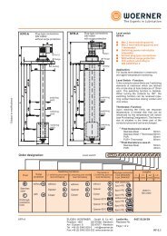
External <strong>Shaft</strong> <strong>Locking</strong> Device Available sizes:<br />
Page #<br />
SLD 900<br />
• Self-centering<br />
• Exceptional concentricity<br />
• Suitable for hollow shafts<br />
• Axial hub position fixed during clamping<br />
Metric 14mm to 240mm<br />
Larger sizes on request<br />
Internal <strong>Shaft</strong> <strong>Locking</strong> <strong>Devices</strong> Available sizes:<br />
Page #<br />
4<br />
• Medium high torque<br />
• Self releasing<br />
• Not self-centering<br />
• Axial hub position fixed during clamping<br />
Metric shafts 17mm to 400mm<br />
Inch shafts ¾" to 7-15/16"<br />
Larger sizes on request<br />
6<br />
SLD 1500<br />
• High torque<br />
• Exceptional concentricity<br />
• Self-centering<br />
• Axial hub position can move during clamping<br />
Metric shafts 18mm to 200mm<br />
Inch shafts ¾" to 4"<br />
Larger sizes on request<br />
8<br />
SLD 1850<br />
• High torque<br />
• Exceptional concentricity<br />
• Self-centering<br />
• Axial hub position fixed during clamping<br />
Metric shafts 18mm to 200mm<br />
Inch shafts ¾" to 4"<br />
Larger sizes on request<br />
10<br />
SLD 1750<br />
• High torque<br />
• Exceptional concentricity<br />
• Self-centering<br />
• Axial hub position can move during clamping<br />
Metric shafts 18mm to 200mm<br />
Inch shafts ¾" to 4"<br />
Larger sizes on request<br />
12<br />
SLD 1350<br />
SLD 1450<br />
• High torque<br />
• Exceptional concentricity<br />
• Self-centering<br />
• Axial hub position fixed during clamping<br />
Metric shafts 18mm to 200mm<br />
Inch shafts ¾" to 4"<br />
Larger sizes on request<br />
14<br />
SLD 2600<br />
• Heavy duty<br />
• Very high torque<br />
• Self-centering<br />
• Exceptional concentricity<br />
Metric shafts 25mm to 240mm<br />
Inch shafts 1" to 6 ½"<br />
Larger sizes on request<br />
16<br />
SLD 1900<br />
• Medium torque<br />
• Allows smaller diameter hubs<br />
• Exceptional concentricity<br />
• Self-centering<br />
• Axial hub position fixed during clamping<br />
Metric shafts 6mm to 130mm<br />
Inch shafts ¾" to 2-15/16"<br />
Larger sizes on request<br />
18<br />
SLD 350<br />
• Low torque<br />
• Small radial dimensions<br />
• Can be combined for greater torque capacity<br />
Metric shafts 6mm to 150mm<br />
Also available with cut ring<br />
Larger sizes on request<br />
20<br />
2 www.lovejoySLD.com
<strong>Shaft</strong> <strong>Locking</strong> <strong>Devices</strong><br />
<strong>Shaft</strong> <strong>Locking</strong> <strong>Devices</strong><br />
Overview<br />
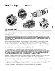
Lovejoy <strong>Shaft</strong> <strong>Locking</strong> <strong>Devices</strong> connect hubs solidly to shafts, using a keyless mechanical interference<br />
fit, to transmit torque or to withstand axial thrust. This mechanical interference fit utilizes<br />
screw tension in the <strong>Shaft</strong> <strong>Locking</strong> Device, converted into radial pressure via an inclined plane.<br />
This pressure expands the <strong>Shaft</strong> <strong>Locking</strong> Device to eliminate the gap between the hub and the<br />
shaft. The <strong>Shaft</strong> <strong>Locking</strong> Device uses the friction bond between the <strong>Shaft</strong> <strong>Locking</strong> Device and<br />
the shaft/hub to create a zero backlash connection. This connection is easily releasable to<br />
remove the mechanical interference fit.<br />
Lovejoy <strong>Shaft</strong> <strong>Locking</strong> <strong>Devices</strong> expand to fill the gap between the shaft and hub, allowing for<br />
easy installation and removal, saving time over traditional interference fit techniques. The contact<br />
pressures created using a <strong>Shaft</strong> <strong>Locking</strong> Device can be greater than traditional interference fit<br />
pressures, allowing for more torque to be transmitted or shorter hubs to be used. The easy<br />
installation also allows the hub to be positioned more accurately on the shaft, and can facilitate<br />
angular timing of the hub.<br />
Benefits<br />
Versus Traditional Keyed connections<br />
• No Backlash due to fit tolerances<br />
• No impact effect from reversing loads<br />
• Ability to adjust axial position and angular timing<br />
• No fretting corrosion due to movement at the fit interface<br />
Versus Traditional Interference fits<br />
• Easier and quicker to install<br />
• Higher contact pressures can transmit greater torques<br />
• Easy and quick to remove without damaging the shaft or hub - even after years of service<br />
Design benefits<br />
• Eliminate cost of machining keyways or splines<br />
• Reduce the shaft stress by removing keyways or splines<br />
• Eliminating keyways often allows the use of a smaller diameter shaft<br />
• Can place anywhere on shaft, and allows for easy angular timing<br />
• Easy removal without damaging the shaft or hub means easier maintenance for your customer<br />
Lovejoy SLD offers several types of <strong>Shaft</strong> <strong>Locking</strong> <strong>Devices</strong>, designed to be used in just about any<br />
application where a shaft connects to a hub.<br />
See Back Cover For Important Safety Instructions<br />
www.lovejoySLD.com<br />
3
<strong>Shaft</strong> <strong>Locking</strong> <strong>Devices</strong><br />
<strong>Shaft</strong> <strong>Locking</strong> <strong>Devices</strong><br />
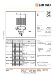
SLD 900 series<br />
d = hub OD diameter<br />
T = tolerance of hub OD<br />
d s = shaft diameter<br />
D = outer diameter of disc<br />
L = total width of disc (relaxed state)<br />
B = width of thrust rings (relaxed state)<br />
l = length of contact<br />
e = width of gap (relaxed state)<br />
C = maximum radial clearance (shaft to hub)<br />
Mt = maximum transmissible torque<br />
M A = screw tightening torque<br />
0.433<br />
D<br />
d<br />
C<br />
ds<br />
L<br />
B<br />
e<br />
M<br />
<strong>Shaft</strong> <strong>Locking</strong> Device Dimensions<br />
Max. <strong>Locking</strong> Screws Weight<br />
Size d T d s D L B l e C Mt M A<br />
(mm) (in) (in) (in) (in) (in) (in) (in) (in) Max (in) (ft-lb) Qty Size (ft-lb) (lb)<br />
14 0.551<br />
0.472<br />
1.496 0.591 0.433 0.354 0.039 0.000551<br />
22<br />
37<br />
4 M5 3 0.33<br />
0.472<br />
37<br />
16 0.630<br />
0.551<br />
1.614 0.728 0.591 0.433 0.079 0.000551<br />
66<br />
5 M5 3 0.44<br />
+0 0.551<br />
79<br />
20 0.787<br />
-0.0013 0.728<br />
1.969 0.906 0.748 0.551 0.098 0.000669<br />
156<br />
6 M5 3 0.44<br />
24 0.945<br />
0.728<br />
120<br />
0.866<br />
1.969 0.906 0.748 0.551 0.098 0.000669<br />
210<br />
6 M5 3 0.44<br />
30 1.181<br />
0.866<br />
177<br />
1.063<br />
2.362 0.984 0.827 0.630 0.098 0.000669<br />
306<br />
6 M5 4 0.66<br />
1.063<br />
297<br />
36 1.417<br />
1.220<br />
2.835 1.063 0.906 0.709 0.098 0.000669<br />
465<br />
5 M6 9 0.99<br />
+0 1.260<br />
465<br />
44 1.732<br />
-0.0015 1.496<br />
3.150 1.142 0.984 0.787 0.098 0.001260<br />
719<br />
7 M6 9 1.32<br />
50 1.969<br />
1.496<br />
693<br />
1.654<br />
3.543 1.220 1.063 0.866 0.098 0.001260<br />
959<br />
8 M6 9 1.76<br />
55 2.165<br />
1.654<br />
885<br />
1.890<br />
3.937 1.339 1.181 0.906 0.138 0.001260<br />
1,401<br />
8 M6 9 2.43<br />
1.890<br />
1,328<br />
62 2.441<br />
2.047<br />
4.331 1.339 1.181 0.906 0.138 0.001260<br />
1,770<br />
10 M6 9 2.87<br />
+0 1.969<br />
1,475<br />
68 2.677<br />
-0.0018 2.362<br />
4.528 1.339 1.181 0.906 0.138 0.001496<br />
2,286<br />
10 M6 9 3.09<br />
75 2.953<br />
2.165<br />
1,844<br />
2.559<br />
5.433 1.496 1.299 0.984 0.157 0.001890<br />
2,876<br />
7 M8 22 3.75<br />
80 3.150<br />
2.362<br />
2,360<br />
2.756<br />
5.709 1.496 1.260 0.984 0.138 0.001890<br />
3,393<br />
7 M8 22 4.85<br />
90 3.543<br />
2.559<br />
3,467<br />
2.953<br />
6.102 1.772 1.535 1.181 0.177 0.001890<br />
5,310<br />
10 M8 22 7.28<br />
2.756<br />
5,089<br />
100 3.937<br />
3.150<br />
6.693 1.949 1.732 1.339 0.197 0.001890<br />
6,638<br />
12 M8 22 10.14<br />
+0 2.953<br />
5,310<br />
110 4.331<br />
-0.0021 3.346<br />
7.283 2.244 1.969 1.535 0.217 0.001890<br />
8,113<br />
9 M10 44 13.01<br />
115 4.528<br />
3.150<br />
6,269<br />
3.543<br />
7.402 2.244 1.969 1.535 0.217 0.001890<br />
8,851<br />
9 M10 44 13.89<br />
125 4.921<br />
3.346<br />
8,113<br />
3.740<br />
8.465 2.402 2.126 1.654 0.236 0.002205<br />
11,063<br />
12 M10 44 18.96<br />
130 5.118<br />
3.543<br />
10,105<br />
3.937<br />
8.465 2.323 2.047 1.654 0.197 0.002205<br />
13,424<br />
12 M10 44 18.08<br />
3.740<br />
11,063<br />
140 5.512<br />
4.134<br />
9.055 2.677 2.362 1.811 0.276 0.002205<br />
14,751<br />
10 M12 74 22.05<br />
+0 4.134<br />
14,751<br />
155 6.102<br />
-0.0025 4.528<br />
10.433 2.756 2.441 1.969 0.236 0.002717<br />
19,177<br />
12 M12 74 33.07<br />
165 6.496<br />
4.528<br />
26,552<br />
4.921<br />
11.417 3.071 2.677 2.205 0.236 0.002717<br />
32,453<br />
8 M16 184 48.50<br />
175 6.890<br />
4.921<br />
29,502<br />
5.315<br />
11.811 3.071 2.677 2.205 0.236 0.003110<br />
36,141<br />
8 M16 184 50.71<br />
185 7.283<br />
5.315<br />
40,566<br />
5.709<br />
12.992 3.780 3.386 2.795 0.295 0.003110<br />
47,942<br />
10 M16 184 79.37<br />
5.512<br />
48,679<br />
195 7.677<br />
6.102<br />
13.780 3.780 3.386 2.795 0.295 0.003110<br />
60,480<br />
12 M16 184 88.18<br />
+0 5.906<br />
56,055<br />
200 7.874<br />
-0.0028 6.299<br />
13.780 3.780 3.386 2.795 0.295 0.003110<br />
65,643<br />
12 M16 184 105.82<br />
220 8.661<br />
6.299<br />
70,068<br />
6.693<br />
14.567 4.488 4.094 3.465 0.315 0.003110<br />
81,132<br />
15 M16 184 119.05<br />
240 9.449<br />
6.693<br />
88,507<br />
7.480<br />
15.945 4.803 4.291 3.622 0.335 0.003110<br />
118,010<br />
12 M20 361 147.71<br />
4 www.lovejoySLD.com
<strong>Shaft</strong> <strong>Locking</strong> <strong>Devices</strong><br />
SLD 900 series<br />
Ordering example:<br />
Brand Model Units Size<br />
SLD 900 MM 50<br />
<strong>Shaft</strong> <strong>Locking</strong> <strong>Devices</strong><br />
C<br />
L<br />
B<br />
M<br />
Selection:<br />
1. Determine the shaft diameter to be used, or the maximum torque to be transmitted.<br />
2. a. If shaft diameter is the primary consideration, verify that the maximum torque to be<br />
transmitted is less than the maximum number listed.<br />
b. If Torque is the primary consideration, use the table to determine the shaft size.<br />
Torque range:<br />
The maximum torque transmission for shaft diameter between those listed can be<br />
approximated using the following formula:<br />
Where:<br />
Sa<br />
Smin<br />
Smax<br />
D d<br />
ds<br />
[<br />
Sa - Smin<br />
] [ ]<br />
Ta =<br />
Smax - Smin x Tmax - Tmin + Tmin<br />
= actual shaft size (in)<br />
= minimum shaft size listed (in)<br />
= maximum shaft size listed (in)<br />
Ta<br />
Tmin<br />
Tmax<br />
= actual torque<br />
= minimum torque listed<br />
= maximum torque listed<br />
e<br />
Mounting against the hub face:<br />
If the SLD 900 is to be mounted against the hub face, we recommend that the hub be<br />
undercut with a radius R > e.<br />
Installation:<br />
1. Clean the hub OD and SLD 900 bore, and lightly lubricate the hub OD.<br />
2. Clean and lightly oil the shaft and hub bore.<br />
3. Insert the shaft or place the hub in the proper position on the shaft.<br />
4. Hand tighten 3 or 4 equally spaced locking screws while making sure the 900 is parallel<br />
to the shaft, then hand tighten the remaining locking screws.<br />
5. Use a torque wrench to gradually tighten all locking screws in sequence. You will probably<br />
need to tighten all locking screws more than once until the specified screw tightening<br />
torque M A is reached.<br />
6. Verify that the screws are tightened to the specified tightening torque.<br />
Removal:<br />
Note: Prior to loosening any locking screws, ensure that no torque or thrust loads are<br />
acting on the shaft, hub, or locking assembly.<br />
1. Gradually loosen the locking screws sequentially. Do not loosen any screws more than<br />
1/2 turn at a time to avoid jamming the collars, and do not remove the screws completely.<br />
2. remove any rust buildup on the shaft in front of the hub prior to removing the hub.<br />
www.lovejoySLD.com<br />
5
<strong>Shaft</strong> <strong>Locking</strong> <strong>Devices</strong><br />
<strong>Shaft</strong> <strong>Locking</strong> <strong>Devices</strong><br />
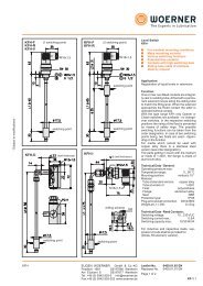
SLD 1500 inch series<br />
d = shaft diameter<br />
T 1 = tolerance of shaft<br />
D = outer diameter of shaft locking device<br />
T 2 = tolerance of hub bore<br />
B = width of thrust rings (relaxed state)<br />
l = length of contact<br />
L = total width (relaxed state)<br />
F = maximum transmissible axial force<br />
Mt = maximum transmissible torque<br />
pH = pressure on the hub<br />
pS = pressure on the shaft<br />
M A = screw tightening torque<br />
-0<br />
D<br />
d<br />
L<br />
B<br />
M<br />
<strong>Shaft</strong> <strong>Locking</strong> Device Dimensions Max. Max. Pressures<br />
<strong>Locking</strong> Screws<br />
Size d T 1 D T 2 B l L F Mt pH pS M A<br />
(in) (in) (in) (in) (in) (in) (in) (in) (lbf) (ft-lb) (psi) (psi) Qty Size (ft-lb)<br />
3/4 0.7500 +0 1.850 -0 0.787 0.669 1.023 6,208 194 13,293 32,789 8 M6 11<br />
7/8 0.8750 -0.0013 1.850 +0.002 0.787 0.669 1.023 6,199 226 13,293 28,105 8 M6 11<br />
1 1.0000 1.969 0.787 0.669 1.023 6,192 258 12,490 24,592 8 M6 11<br />
1 1/8 1.1250 2.165 0.787 0.669 1.023 9,301 436 17,038 32,789 12 M6 11<br />
1 3/16 1.1875 2.159 0.813 0.669 1.049 9,297 460 17,086 31,064 12 M6 11<br />
1 1/4 1.2500 2.362 0.787 0.669 1.023 9,312 485 15,617 29,511 12 M6 11<br />
1 3/8 1.3750 2.365 0.787 0.669 1.023 9,303 533 15,598 26,828 12 M6 11<br />
1 7/16 1.4375 2.559 0.787 0.669 1.023 11,637 697 18,019 32,077 15 M6 11<br />
1 1/2 1.5000 +0 2.559 0.787 0.669 1.023 11,632 727 18,019 30,740 15 M6 11<br />
1 5/8 1.6250 -0.0025 2.953 +0.0025 0.945 0.787 1.260 17,516 1,186 19,993 36,331 12 M8 27<br />
1 11/16 1.6875 2.953 0.945 0.787 1.260 17,522 1,232 19,993 34,986 12 M8 27<br />
1 3/4 1.7500 2.953 0.945 0.787 1.260 17,513 1,277 19,993 33,736 12 M8 27<br />
1 7/8 1.8750 3.150 0.945 0.787 1.260 17,510 1,368 18,742 31,487 12 M8 27<br />
1 15/16 1.9375 3.150 0.945 0.787 1.260 16,487 1,331 17,640 28,679 12 M8 27<br />
2 2.0000 3.346 0.945 0.787 1.260 20,604 1,717 20,758 34,728 15 M8 27<br />
2 1/8 2.1250 3.346 0.945 0.787 1.260 20,612 1,825 20,758 32,686 15 M8 27<br />
2 3/16 2.1875 3.543 0.945 0.787 1.260 20,604 1,878 19,604 31,752 15 M8 27<br />
2 1/4 2.2500 3.543 0.945 0.787 1.260 20,608 1,932 19,604 30,870 15 M8 27<br />
2 3/8 2.3750 3.531 0.945 0.787 1.260 20,605 2,039 19,671 29,245 15 M8 27<br />
2 7/16 2.4375 3.740 0.945 0.787 1.260 20,608 2,093 18,571 28,495 15 M8 27<br />
2 1/2 2.5000<br />
+0<br />
3.740<br />
-0<br />
0.945 0.787 1.260 20,611 2,147 18,571 27,783 15 M8 27<br />
2 9/16 2.5625<br />
-0.0030<br />
3.737<br />
+0.003<br />
0.945 0.787 1.260 20,605 2,200 18,586 27,105 15 M8 27<br />
2 5/8 2.6250 4.331 1.102 0.945 1.496 31,122 3,404 20,169 33,276 15 M10 52<br />
2 11/16 2.6875 4.331 1.102 0.945 1.496 31,122 3,485 20,169 32,503 15 M10 52<br />
2 3/4 2.7500 4.337 1.102 0.945 1.496 31,121 3,566 20,141 31,764 15 M10 52<br />
2 7/8 2.8750 4.528 1.102 0.945 1.496 31,121 3,728 19,291 30,383 15 M10 52<br />
2 15/16 2.9375 4.528 1.102 0.945 1.496 31,120 3,809 19,291 29,736 15 M10 52<br />
3 3.0000 4.724 1.102 0.945 1.496 31,120 3,890 18,491 29,117 15 M10 52<br />
3 1/8 3.1250 4.724 1.102 0.945 1.496 31,119 4,052 18,491 27,952 15 M10 52<br />
3 1/4 3.2500 4.921 1.102 0.945 1.496 31,119 4,214 17,751 26,877 15 M10 52<br />
3 3/8 3.3750 4.921 1.102 0.945 1.496 31,118 4,376 17,751 25,882 15 M10 52<br />
3 7/16 3.4375 5.118 1.102 0.945 1.496 31,118 4,457 17,067 25,411 15 M10 52<br />
3 1/2 3.5000 5.118 1.102 0.945 1.496 31,118 4,538 17,067 24,957 15 M10 52<br />
3 3/4 3.7500 +0 5.305 -0 1.102 0.945 1.496 37,344 5,835 19,759 27,952 18 M10 52<br />
3 7/8 3.8750 -0.0035 5.709 +0.0035 1.260 1.024 1.732 45,560 7,356 20,676 30,456 15 M12 91<br />
3 15/16 3.9375 5.709 1.260 1.024 1.732 46,068 7,558 20,906 30,306 15 M12 91<br />
4 4.0000 5.843 1.260 1.024 1.732 46,062 7,677 20,423 29,833 15 M12 91<br />
4 3/16 4.1875 6.102 1.260 1.024 1.732 46,063 8,037 19,556 28,497 15 M12 91<br />
4 7/16 4.4375 6.496 1.260 1.024 1.732 49,136 9,085 19,594 28,684 16 M12 91<br />
4 1/2 4.5000 6.496 1.260 1.024 1.771 49,136 9,213 19,594 28,286 16 M12 91<br />
4 15/16 4.9375 7.087 1.496 1.339 1.968 61,421 12,636 17,169 24,643 20 M12 91<br />
5 5.0000 7.087 1.496 1.339 1.968 61,421 12,796 17,169 24,335 20 M12 91<br />
5 7/16 5.4375 7.480 1.496 1.339 1.968 67,562 15,307 17,894 24,615 22 M12 91<br />
5 1/2 5.5000<br />
+0<br />
7.492<br />
-0<br />
1.496 1.339 1.968 67,562 15,483 17,865 24,335 22 M12 91<br />
6 6.0000<br />
-0.0040<br />
8.268<br />
+0.0040<br />
1.496 1.339 1.968 79,844 19,961 19,132 26,363 26 M12 91<br />
6 7/16 6.4375 8.858 1.732 1.496 2.283 86,683 23,251 17,352 23,877 22 M14 138<br />
6 1/2 6.5000 8.858 1.732 1.496 2.283 86,684 23,477 17,352 23,647 22 M14 138<br />
6 15/16 6.9375 9.252 1.732 1.496 2.283 94,564 27,335 18,123 24,170 24 M14 138<br />
7 7.0000 9.252 1.732 1.496 2.283 94,563 27,581 18,123 23,954 24 M14 138<br />
7 1/2 7.5000<br />
+0<br />
9.823<br />
-0<br />
2.051 1.811 2.602 110,326 34,477 16,451 21,546 28 M14 138<br />
7 7/8 7.8750 10.235 2.051 1.811 2.602 118,205 38,786 16,917 21,986 30 M14 138<br />
-0.0045<br />
+0.0045<br />
8 8.0000 10.504 2.051 1.811 2.602 118,206 39,402 16,483 21,643 30 M14 138<br />
6 www.lovejoySLD.com
<strong>Shaft</strong> <strong>Locking</strong> <strong>Devices</strong><br />
SLD 1500 metric series<br />
Ordering example:<br />
Brand Model Units Size<br />
SLD 1500 IN 1 3/8<br />
SLD 1500 MM 50x80<br />
<strong>Shaft</strong> <strong>Locking</strong> <strong>Devices</strong><br />
L<br />
B<br />
M<br />
D<br />
d<br />
<strong>Shaft</strong> <strong>Locking</strong> Device Dimensions Max. Max.<br />
Pressures<br />
<strong>Locking</strong> Screws<br />
Size d T 1 D T 2 B l L F Mt pH pS M A<br />
(in) (in) (in) (in) (in) (in) (in) (in) (lbf) (ft-lb) (psi) (psi) Qty Size (ft-lb)<br />
17x47 0.669 1.850 0.787 0.669 1.024 6,083 170 13,343 36,985 8 M6 11.80<br />
18x47 0.709 1.850 0.787 0.669 1.024 6,245 184 13,343 34,954 8 M6 11.80<br />
19x47 0.748 +0 1.850 -0 0.787 0.669 1.024 6,153 192 13,343 33,069 8 M6 11.80<br />
20x47 0.787 -0.0013 1.850 +0.002 0.787 0.669 1.024 6,295 207 13,343 31,473 8 M6 11.80<br />
22x47 0.866 1.850 0.787 0.669 1.024 6,336 229 13,343 28,572 8 M6 11.80<br />
24x50 0.945 1.969 0.787 0.669 1.024 6,182 243 12,618 26,252 8 M6 11.80<br />
25x50 0.984 1.969 0.787 0.669 1.024 6,295 258 12,618 25,237 8 M6 11.80<br />
28x55 1.102 2.165 0.787 0.669 1.024 9,314 428 17,114 33,794 12 M6 11.80<br />
30x55 1.181 2.165 0.787 0.669 1.024 9,442 465 17,114 31,473 12 M6 11.80<br />
32x60 1.260 2.362 0.787 0.669 1.024 9,414 494 15,954 29,443 12 M6 11.80<br />
35x60 1.378 2.362 0.787 0.669 1.024 9,378 538 15,954 26,977 12 M6 11.80<br />
38x65 1.496 +0 2.559 -0 0.787 0.669 1.024 11,714 730 18,130 31,038 15 M6 11.80<br />
40x65 1.575 -0.0025 2.559 +0.0025 0.787 0.669 1.024 11,690 767 18,130 29,443 15 M6 11.80<br />
42x75 1.654 2.953 0.945 0.787 1.260 17,128 1,180 20,305 34,809 12 M8 28<br />
45x75 1.772 2.953 0.945 0.787 1.260 16,986 1,254 20,305 32,489 12 M8 28<br />
48x80 1.890 3.150 0.945 0.787 1.260 16,861 1,328 17,405 30,458 12 M8 28<br />
50x80 1.969 3.150 0.945 0.787 1.260 17,085 1,401 18,855 29,298 12 M8 28<br />
55x85 2.165 3.346 0.945 0.787 1.260 21,255 1,918 21,756 33,214 15 M8 28<br />
60x90 2.362 +0 3.543 -0 0.945 0.787 1.260 21,357 2,102 20,305 30,458 15 M8 28<br />
65x95 2.559<br />
-0.0030<br />
3.740<br />
+0.0030<br />
0.945 0.787 1.260 21,443 2,286 18,855 28,137 15 M8 28<br />
70x110 2.756 4.331 1.102 0.945 1.496 34,364 3,946 23,206 34,954 15 M10 55<br />
75x115 2.953 4.528 1.102 0.945 1.496 34,351 4,226 21,756 32,634 15 M10 55<br />
80x120 3.150 4.724 1.102 0.945 1.496 34,283 4,499 20,305 30,603 15 M10 55<br />
85x125 3.346 4.921 1.102 0.945 1.496 34,383 4,794 20,305 28,863 15 M10 55<br />
90x130 3.543 +0 5.118 -0 1.102 0.945 1.496 34,471 5,089 18,855 27,267 18 M10 55<br />
95x135 3.740 -0.0035 5.315 +0.0035 1.102 0.945 1.496 41,176 6,417 21,756 30,893 18 M10 55<br />
100x145 3.937 5.709 1.260 1.024 1.732 50,357 8,261 23,206 33,214 15 M12 96<br />
110x155 4.331 6.102 1.260 1.024 1.732 50,275 9,072 21,756 30,168 15 M12 96<br />
120x165 4.724 6.496 1.260 1.024 1.732 53,579 10,547 21,756 29,443 16 M12 96<br />
130x180 5.118 7.087 1.496 1.339 1.969 67,097 14,309 18,855 25,962 20 M12 96<br />
140x190 5.512 +0 7.480 -0 1.496 1.339 1.969 73,866 16,964 20,305 26,542 22 M12 96<br />
150x200 5.906<br />
-0.0040<br />
7.874<br />
+0.0040<br />
1.496 1.339 1.969 80,631 19,840 20,305 26,977 24 M12 96<br />
160x210 6.299 8.268 1.496 1.339 1.969 87,113 22,864 21,756 27,412 26 M12 96<br />
170x225 6.693 8.858 1.732 1.496 2.283 96,007 26,774 20,305 25,527 22 M14 148<br />
180x235 7.087 9.252 1.732 1.496 2.283 104,911 30,978 20,305 26,252 24 M14 148<br />
190x250 7.480 9.843 2.047 1.811 2.598 122,580 38,206 18,855 23,931 28 M14 148<br />
200x260 7.874 +0 10.236 -0 2.047 1.811 2.598 131,064 43,000 18,855 24,366 30 M14 148<br />
220x285 8.661 -0.0045 11.220 +0.0045 2.205 1.969 2.835 151,439 54,653 18,855 23,641 26 M16 221<br />
240x305 9.449 12.008 2.205 1.969 2.835 174,602 68,741 20,305 24,947 30 M16 221<br />
260x325 10.236 12.795 2.205 1.969 2.835 198,005 84,451 21,756 26,107 34 M16 221<br />
+0<br />
-0<br />
280x355 11.024 13.976 2.598 2.362 3.307 226,415 103,996 18,855 23,061 32 M18 302<br />
-0.0051<br />
+0.0051<br />
300x375 11.811 14.764 2.598 2.362 3.307 254,783 125,386 20,305 24,221 36 M18 302<br />
320x405 12.598 15.945 3.071 2.835 3.858 330,891 173,696 20,305 24,511 36 M20 435<br />
340x425 13.386<br />
+0<br />
16.732<br />
-0<br />
3.071 2.835 3.858 330,601 184,391 18,855 23,206 36 M20 435<br />
360x455 14.173 17.913 3.543 3.307 4.409 410,901 242,658 18,855 23,206 36 M22 583<br />
-0.0055<br />
+0.0055<br />
380x475 14.961 18.701 3.543 3.307 4.409 409,862 255,492 17,405 22,046 36 M22 583<br />
400x495 15.748 19.488 3.543 3.307 4.409 410,276 269,210 17,405 20,885 36 M22 583<br />
420x515 16.535 20.276 3.543 3.307 4.409 455,399 313,759 17,405 22,046 40 M22 583<br />
440x545 17.323 21.457 4.016 3.780 4.961 626,808 452,421 20,305 25,382 40 M24 885<br />
+0<br />
-0<br />
460x565 18.110 22.244 4.016 3.780 4.961 626,826 472,999 18,855 24,366 40 M24 885<br />
480x585 18.898<br />
-0.0061<br />
23.031<br />
+0.0061<br />
4.016 3.780 4.961 658,222 518,285 20,305 24,511 42 M24 885<br />
500x605 19.685 23.819 4.016 3.780 4.961 689,534 565,563 20,305 24,656 44 M24 885<br />
www.lovejoySLD.com<br />
7
<strong>Shaft</strong> <strong>Locking</strong> <strong>Devices</strong><br />
<strong>Shaft</strong> <strong>Locking</strong> <strong>Devices</strong><br />
SLD 1850 inch series<br />
d = shaft diameter<br />
T 1 = tolerance of shaft<br />
D = outer diameter of shaft locking device<br />
T 2 = tolerance of hub bore<br />
B = width of thrust rings (relaxed state)<br />
l = length of contact<br />
L = total width (relaxed state)<br />
F = maximum transmissible axial force<br />
Mt = maximum transmissible torque<br />
pH = pressure on the hub<br />
pS = pressure on the shaft<br />
M A = screw tightening torque<br />
-0<br />
D<br />
d<br />
L<br />
B<br />
M<br />
<strong>Shaft</strong> <strong>Locking</strong> Device Dimensions Max. Max. Pressures <strong>Locking</strong> Screws<br />
Size d T 1 D T 2 B l L F Mt pH pS M A<br />
(in) (in) (in) (in) (in) (in) (in) (in) (lbf) (ft-lb) (psi) (psi) Qty Size (ft-lb)<br />
3/4 0.750 1.850 -0 1.102 0.669 1.339 9,181 287 19,725 36,840 6 M6 10<br />
+0<br />
7/8 0.875 +0.0015<br />
-0.0013 1.850 1.102 0.669 1.339 9,104 332 19,725 31,763 6 M6 10<br />
1 1.000 1.969 1.102 0.669 1.339 9,063 378 18,565 27,992 6 M6 10<br />
1 1/8 1.125 2.165 1.102 0.669 1.339 9,346 438 16,824 24,076 6 M6 10<br />
1 3/16 1.188 2.165 1.102 0.669 1.339 9,153 453 16,824 23,351 6 M6 10<br />
1 1/4 1.250 2.362 1.102 0.669 1.339 12,377 645 20,595 29,153 8 M6 10<br />
1 3/8 1.375 2.362 -0 1.102 0.669 1.339 12,307 705 20,595 26,687 8 M6 10<br />
1 7/16 1.438 2.559 +0.0018 1.102 0.669 1.339 12,437 745 19,000 25,237 8 M6 10<br />
+0<br />
1 1/2 1.500<br />
-0.0016<br />
2.559 1.102 0.669 1.339 12,238 765 19,000 24,511 8 M6 10<br />
1 5/8 1.625 2.953 1.299 0.787 1.614 23,377 1,583 26,832 36,405 8 M8 26<br />
1 11/16 1.688 2.953 1.299 0.787 1.614 23,612 1,660 26,832 34,664 8 M8 26<br />
1 3/4 1.750 2.953 1.299 0.787 1.614 23,295 1,699 26,832 33,939 8 M8 26<br />
1 7/8 1.875 3.150 1.319 0.787 1.614 23,725 1,853 25,237 31,038 8 M8 26<br />
1 15/16 1.938 3.150 1.319 0.787 1.614 23,434 1,892 25,237 30,458 8 M8 26<br />
2 2.000 3.150 1.319 0.787 1.614 23,631 1,969 25,237 29,298 8 M8 26<br />
2 1/8 2.125 3.346 1.319 0.787 1.614 23,549 2,085 23,641 27,557 8 M8 26<br />
2 3/16 2.188 3.346 1.319 0.787 1.614 23,726 2,163 23,641 26,687 8 M8 26<br />
2 1/4 2.250 3.543 1.319 0.787 1.614 23,476 2,201 22,336 26,107 8 M8 26<br />
2 3/8 2.375 3.543 1.319 0.787 1.614 23,411 2,317 22,336 24,802 8 M8 26<br />
-0<br />
2 7/16 2.438 3.740<br />
+0<br />
+0.0022<br />
1.319 0.787 1.614 23,573 2,394 21,176 24,076 8 M8 26<br />
2 1/2 2.500<br />
-0.0018<br />
3.740 1.319 0.787 1.614 23,720 2,471 21,176 23,351 8 M8 26<br />
2 9/16 2.563 3.740 1.319 0.787 1.614 23,508 2,510 21,176 22,916 8 M8 26<br />
2 11/16 2.688 4.331 1.575 0.945 1.969 38,202 4,278 24,802 29,733 8 M10 52<br />
2 3/4 2.750 4.331 1.575 0.945 1.969 38,435 4,404 24,802 29,008 8 M10 52<br />
2 7/8 2.875 4.528 1.575 0.945 1.969 38,340 4,593 23,786 27,702 8 M10 52<br />
2 15/16 2.938 4.528 1.575 0.945 1.969 38,549 4,718 23,786 26,977 8 M10 52<br />
3 3.000 4.724 1.575 0.945 1.969 38,253 4,782 22,771 26,687 8 M10 52<br />
3 1/4 3.250 4.921 1.575 0.945 1.969 48,203 6,527 27,412 30,458 10 M10 52<br />
3 3/8 3.375 4.921 1.575 0.945 1.969 48,096 6,763 27,412 29,443 10 M10 52<br />
3 7/16 3.438 5.118 1.575 0.945 1.969 47,767 6,842 26,252 29,153 10 M10 52<br />
3 1/2 3.500 +0 5.118 1.575 0.945 1.969 47,996 6,999 26,252 28,427 10 M10 52<br />
3 3/4 3.750<br />
-0.0022<br />
5.315<br />
+0.0025<br />
1.575 0.945 1.969 47,813 7,471 25,382 26,687 10 M10 52<br />
3 15/16 3.938 5.709 1.732 1.024 2.205 53,291 8,743 24,221 28,137 8 M12 85<br />
4 4.000 5.709 1.732 1.024 2.205 53,507 8,918 24,221 27,557 8 M12 85<br />
8 www.lovejoySLD.com
<strong>Shaft</strong> <strong>Locking</strong> <strong>Devices</strong><br />
SLD 1850 metric series<br />
Ordering example:<br />
Brand Model Units Size<br />
SLD 1850 IN 1 3/8<br />
SLD 1850 MM 50x80<br />
<strong>Shaft</strong> <strong>Locking</strong> <strong>Devices</strong><br />
L<br />
B<br />
d<br />
D<br />
M<br />
<strong>Shaft</strong> <strong>Locking</strong> Device Dimensions<br />
Max. Max. Pressures <strong>Locking</strong> Screws<br />
Size d T 1 D T 2 B l L F Mt pH pS M A<br />
(in) (in) (in) (in) (in) (in) (in) (in) (lbf) (ft-lb) (psi) (psi) Qty Size (ft-lb)<br />
18x47 0.709 1.850 1.102 0.669 1.339 9,242 273 19,725 38,870 6 M6 10<br />
19x47 0.748 1.850 1.102 0.669 1.339 9,253 288 19,725 36,840 6 M6 10<br />
20x47 0.787 1.850 1.102 0.669 1.339 9,217 302 19,725 34,954 6 M6 10<br />
-0<br />
22x47 0.866 +0 1.850<br />
+0.0015<br />
1.102 0.669 1.339 9,197 332 19,725 31,763 6 M6 10<br />
24x50 0.945 -0.0013 1.969 1.102 0.669 1.339 9,198 362 18,565 29,153 6 M6 10<br />
25x50 0.984 1.969 1.102 0.669 1.339 9,208 378 18,565 27,992 6 M6 10<br />
28x55 1.102 2.165 1.102 0.669 1.339 9,201 423 16,824 24,947 6 M6 10<br />
30x55 1.181 2.165 1.102 0.669 1.339 9,202 453 16,824 23,351 6 M6 10<br />
32x60 1.260 2.362 1.102 0.669 1.339 12,280 645 20,595 29,153 8 M6 10<br />
35x60 1.378 2.362 1.102 0.669 1.339 12,281 705 20,595 26,687 8 M6 10<br />
38x65 1.496 2.559 1.102 0.669 1.339 12,270 765 19,000 24,511 8 M6 10<br />
-0<br />
40x65 1.575 +0 2.559<br />
+0.0018<br />
1.102 0.669 1.339 12,275 805 19,000 23,351 8 M6 10<br />
42x75 1.654 -0.0015 2.953 1.299 0.787 1.614 23,541 1,622 26,832 32,343 8 M8 26<br />
45x75 1.772 2.953 1.299 0.787 1.614 23,540 1,738 26,832 33,214 8 M8 26<br />
48x80 1.890 3.150 1.319 0.787 1.614 23,539 1,853 25,237 31,038 8 M8 26<br />
50x80 1.969 3.150 1.319 0.787 1.614 23,533 1,930 25,237 29,878 8 M8 26<br />
55x85 2.165 3.346 1.319 0.787 1.614 23,535 2,123 23,641 27,122 8 M8 26<br />
60x90 2.362 3.543 1.319 0.787 1.614 23,537 2,317 22,336 24,802 8 M8 26<br />
65x95 2.559 +0 3.740 -0 1.319 0.787 1.614 23,539 2,510 21,176 22,916 8 M8 26<br />
70x110 2.756 -0.0018 4.331 +0.0021 1.575 0.945 1.969 38,352 4,404 24,802 29,008 8 M10 52<br />
75x115 2.953 4.528 1.575 0.945 1.969 38,349 4,718 23,786 26,977 8 M10 52<br />
80x120 3.150 4.724 1.575 0.945 1.969 38,352 5,033 22,771 25,382 8 M10 52<br />
85x125 3.346 4.921 1.575 0.945 1.969 47,940 6,685 27,412 29,733 10 M10 52<br />
90x130 3.543 5.118 1.575 0.945 1.969 47,939 7,078 26,252 28,137 10 M10 52<br />
95x135 3.740 +0 5.315 1.575 0.945 1.969 47,939 7,471 25,382 26,687 10 M10 52<br />
-0.0021<br />
-0<br />
100x145 3.937 5.709<br />
+0.0025<br />
1.732 1.024 2.205 53,298 8,743 24,221 28,137 8 M12 85<br />
110x155 4.331 6.102 1.732 1.024 2.205 53,296 9,617 22,626 23,061 8 M12 85<br />
120x165 4.724 6.496 1.732 1.024 2.205 59,960 11,803 23,931 23,786 9 M12 85<br />
130x180 5.118 7.087 2.047 1.339 2.520 79,946 17,049 22,336 24,366 12 M12 85<br />
140x190 5.512 7.480 2.126 1.339 2.677 81,609 18,742 21,611 22,191 9 M14 136<br />
150x200 5.906 +0 7.874 2.126 1.339 2.677 90,676 22,312 22,771 23,061 10 M14 136<br />
160x210 6.299 -0.0025 8.268 -0 2.126 1.339 2.677 108,813 28,560 26,107 25,817 12 M14 136<br />
170x225 6.693 8.858 +0.0028 2.520 1.732 3.071 108,813 30,345 18,855 20,305 12 M14 136<br />
180x235 7.087 9.252 2.520 1.732 3.071 108,813 32,130 17,985 19,145 12 M14 136<br />
190x250<br />
200x260<br />
7.480<br />
7.874<br />
+0<br />
-0.0028<br />
9.843<br />
10.236 -0<br />
+0.0032<br />
2.520<br />
2.520<br />
1.732<br />
1.732<br />
3.071<br />
3.071<br />
136,016<br />
136,016<br />
42,394<br />
44,625<br />
21,176<br />
20,305<br />
22,626<br />
21,611<br />
15<br />
15<br />
M14<br />
M14<br />
136<br />
136<br />
www.lovejoySLD.com<br />
9
<strong>Shaft</strong> <strong>Locking</strong> <strong>Devices</strong><br />
<strong>Shaft</strong> <strong>Locking</strong> <strong>Devices</strong><br />
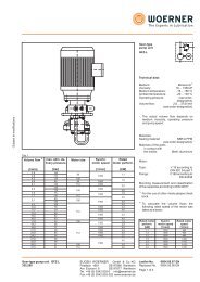
SLD 1750 inch series<br />
d = shaft diameter<br />
T 1 = tolerance of shaft<br />
D = outer diameter of shaft locking device<br />
T 2 = tolerance of hub bore<br />
D 1 = diameter of flange<br />
A = width to flange<br />
B = width of thrust rings (relaxed state)<br />
l = length of contact<br />
L = total width (relaxed state)<br />
F = maximum transmissible axial force<br />
Mt = maximum transmissible torque<br />
pH = pressure on the hub<br />
pS = pressure on the shaft<br />
M A = screw tightening torque<br />
-0<br />
D1<br />
d<br />
L<br />
B<br />
A<br />
M<br />
D<br />
<strong>Shaft</strong> <strong>Locking</strong> Device Dimensions<br />
Max.<br />
Max.<br />
Pressures<br />
<strong>Locking</strong> Screws<br />
Size d T 1 D T 2 D 1 A B l L F Mt pH pS M A<br />
(in) (in) (in) (in) (in) (in) (in) (in) (in) (in) (lbf) (ft-lb) (psi) (psi) Qty Size (ft-lb)<br />
3/4 0.7500 1.850 -0 2.087 0.866 1.102 0.669 1.339 7,623 238 15,515 26,024 6 M6 13<br />
+0<br />
+0.0015<br />
7/8 0.8750 -0.0013 1.850 2.087 0.866 1.102 0.669 1.339 7,623 278 15,515 22,306 6 M6 13<br />
1 1.0000 1.969 2.205 0.866 1.102 0.669 1.339 7,623 318 14,577 19,518 6 M6 13<br />
1 1/8 1.1250 2.165 2.421 0.866 1.102 0.669 1.339 7,623 357 13,258 17,349 6 M6 13<br />
1 3/16 1.1875 2.165 2.421 0.866 1.102 0.669 1.339 7,623 377 13,258 16,436 6 M6 13<br />
1 1/4 1.2500 2.362 2.638 0.866 1.102 0.669 1.339 10,164 529 16,202 20,819 8 M6 13<br />
1 3/8 1.3750 2.362 -0 2.638 0.866 1.102 0.669 1.339 10,164 582 16,202 18,926 8 M6 13<br />
1 7/16 1.4375 2.559 +0.0018 2.835 0.866 1.102 0.669 1.339 10,164 609 14,955 18,103 8 M6 13<br />
+0<br />
1 1/2 1.5000 -0.0016 2.559 2.835 0.866 1.102 0.669 1.339 10,164 635 14,955 17,349 8 M6 13<br />
1 5/8 1.6250 2.953 3.307 0.984 1.299 0.787 1.614 18,806 1,273 20,381 24,691 8 M8 30<br />
1 11/16 1.6875 2.953 3.307 0.984 1.299 0.787 1.614 18,806 1,322 20,381 23,777 8 M8 30<br />
1 3/4 1.7500 2.953 3.307 0.984 1.299 0.787 1.614 18,806 1,371 20,381 22,928 8 M8 30<br />
1 7/8 1.8750 3.150 3.504 0.945 1.319 0.787 1.614 18,806 1,469 19,106 21,399 8 M8 30<br />
1 15/16 1.9375 3.150 3.504 0.945 1.319 0.787 1.614 18,806 1,518 19,106 20,709 8 M8 30<br />
2 2.0000 3.150 3.504 0.945 1.319 0.787 1.614 18,806 1,567 19,109 20,062 8 M8 30<br />
2 1/8 2.1250 3.346 3.700 0.945 1.319 0.787 1.614 18,806 1,665 17,987 18,882 8 M8 30<br />
2 3/16 2.1875 3.346 3.700 0.945 1.319 0.787 1.614 18,806 1,714 17,987 18,342 8 M8 30<br />
2 1/4 2.2500 3.543 3.897 0.945 1.319 0.787 1.614 18,806 1,763 16,987 17,833 8 M8 30<br />
2 3/8 2.3750 3.543 3.897 0.945 1.319 0.787 1.614 18,806 1,861 16,987 16,894 8 M8 30<br />
-0<br />
2 7/16 2.4375 3.740<br />
+0<br />
+0.0022 4.094 0.945 1.319 0.787 1.614 18,806 1,910 16,092 16,461 8 M8 30<br />
2 1/2 2.5000 -0.0018 3.740 4.094 0.945 1.319 0.787 1.614 18,806 1,959 16,092 16,049 8 M8 30<br />
2 9/16 2.5625 3.740 4.094 0.945 1.319 0.787 1.614 18,806 2,008 16,092 15,658 8 M8 30<br />
2 11/16 2.6875 4.331 4.685 1.142 1.575 0.945 1.969 31,017 3,473 19,100 20,520 8 M10 61<br />
2 3/4 2.7500 4.331 4.685 1.142 1.575 0.945 1.969 31,017 3,554 19,100 20,053 8 M10 61<br />
2 7/8 2.8750 4.528 4.882 1.142 1.575 0.945 1.969 31,017 3,716 18,269 19,182 8 M10 61<br />
2 15/16 2.9375 4.528 4.882 1.142 1.575 0.945 1.969 31,017 3,796 18,269 18,773 8 M10 61<br />
3 3.0000 4.724 5.078 1.142 1.575 0.945 1.969 31,017 3,877 17,511 18,382 8 M10 61<br />
3 1/4 3.2500 4.921 5.275 1.142 1.575 0.945 1.969 31,017 4,200 16,810 16,968 8 M10 61<br />
3 3/8 3.3750 4.921 5.275 1.142 1.575 0.945 1.969 38,771 5,452 21,012 20,425 10 M10 61<br />
3 7/16 3.4375 5.118 5.470 1.142 1.575 0.945 1.969 38,771 5,553 20,203 20,053 10 M10 61<br />
+0<br />
3 1/2 3.5000 5.118 5.470 1.142 1.575 0.945 1.969 38,771 5,654 20,203 19,695 10 M10 61<br />
-0.0022 +0.0025<br />
3 3/4 3.7500 5.315 5.669 1.142 1.575 0.945 1.969 38,771 6,058 19,455 18,382 10 M10 61<br />
3 15/16 3.9375 5.708 6.603 1.220 1.732 1.024 2.205 45,836 7,520 19,768 18,627 8 M12 107<br />
4 4.0000 5.709 6.603 1.220 1.732 1.024 2.205 45,836 7,639 19,766 18,336 8 M12 107<br />
10 www.lovejoySLD.com
<strong>Shaft</strong> <strong>Locking</strong> <strong>Devices</strong><br />
SLD 1750 metric series<br />
<strong>Shaft</strong> <strong>Locking</strong> <strong>Devices</strong><br />
L<br />
B<br />
A<br />
Ordering example:<br />
Brand Model Units Size<br />
SLD 1750 IN 1 3/8<br />
SLD 1750 MM 50x80<br />
d<br />
D1<br />
M<br />
D<br />
<strong>Shaft</strong> <strong>Locking</strong> Device Dimensions Max. Max. Pressures <strong>Locking</strong> Screws<br />
Size d T 1 D T 2 D 1 A B l L F Mt pH pS M A<br />
(in) (in) (in) (in) (in) (in) (in) (in) (in) (lbf) (ft-lb) (psi) (psi) Qty Size (ft-lb)<br />
18x47 0.7087 1.850 2.087 0.866 1.102 0.669 1.339 7,242 214 16,328 28,991 6 M6 10<br />
19x47 0.7480 1.850 2.087 0.866 1.102 0.669 1.339 7,242 226 16,328 27,465 6 M6 10<br />
20x47 0.7874 1.850 -0 2.087 0.866 1.102 0.669 1.339 7,242 238 16,328 26,092 6 M6 10<br />
22x47 0.8661 +0 1.850 +0.0015 2.087 0.866 1.102 0.669 1.339 7,242 261 16,328 23,720 6 M6 10<br />
24x50 0.9449 -0.0013 1.969 2.205 0.866 1.102 0.669 1.339 7,242 285 15,348 21,743 6 M6 10<br />
25x50 0.9843 1.969 2.205 0.866 1.102 0.669 1.339 7,242 297 15,348 20,874 6 M6 10<br />
28x55 1.1024 2.165 2.421 0.866 1.102 0.669 1.339 7,242 333 13,953 18,637 6 M6 10<br />
30x55 1.1811 2.165 2.421 0.866 1.102 0.669 1.339 7,242 356 13,953 17,395 6 M6 10<br />
32x60 1.2598 2.362 2.638 0.866 1.102 0.669 1.339 9,656 507 17,054 21,743 8 M6 10<br />
35x60 1.3780 2.362 2.638 0.866 1.102 0.669 1.339 9,656 554 17,054 19,880 8 M6 10<br />
38x65 1.4961 2.559 -0 2.835 0.866 1.102 0.669 1.339 9,656 602 15,742 18,310 8 M6 10<br />
40x65 1.5748 +0 2.559 +0.0018 2.835 0.866 1.102 0.669 1.339 9,656 634 15,742 17,395 8 M6 10<br />
42x75 1.6535 -0.0015 2.953 3.307 0.984 1.299 0.787 1.614 17,866 1,231 21,455 25,542 8 M8 26<br />
45x75 1.7717 2.953 3.307 0.984 1.299 0.787 1.614 17,866 1,319 21,455 23,839 8 M8 26<br />
48x80 1.8898 3.150 3.504 0.945 1.319 0.787 1.614 17,866 1,407 20,114 22,349 8 M8 26<br />
50x80 1.9685 3.150 3.504 0.945 1.319 0.787 1.614 17,866 1,465 20,114 21,455 8 M8 26<br />
55x85 2.1654 3.346 3.583 0.945 1.319 0.787 1.614 17,866 1,612 18,931 19,505 8 M8 26<br />
60x90 2.3622 3.543 3.898 0.945 1.319 0.787 1.614 17,866 1,758 17,880 17,880 8 M8 26<br />
65x95 2.5591 +0 3.740 -0 4.094 0.945 1.319 0.787 1.614 17,866 1,905 16,939 16,504 8 M8 26<br />
70x110 2.7559 -0.0018 4.331 +0.0021 4.685 1.142 1.575 0.945 1.969 29,466 3,384 20,106 21,064 8 M10 52<br />
75x115 2.9528 4.528 4.882 1.142 1.575 0.945 1.969 29,466 3,625 19,232 19,659 8 M10 52<br />
80x120 3.1496 4.724 5.079 1.142 1.575 0.945 1.969 29,466 3,867 18,431 18,431 8 M10 52<br />
85x125 3.3465 4.921 5.276 1.142 1.575 0.945 1.969 36,832 5,136 22,117 21,683 10 M10 52<br />
90x130 3.5433 5.118 5.472 1.142 1.575 0.945 1.969 36,832 5,438 21,266 20,479 10 M10 52<br />
95x135 3.7402 +0 5.315 5.669 1.142 1.575 0.945 1.969 36,832 5,740 20,479 19,401 10 M10 52<br />
-0.0021<br />
-0<br />
100x145 3.9370 5.709<br />
+0.0025<br />
6.063 1.220 1.732 1.024 2.205 43,544 7,143 20,807 19,610 8 M12 85<br />
110x155 4.3307 6.102 6.457 1.220 1.732 1.024 2.205 43,544 7,857 19,464 17,827 8 M12 85<br />
120x165 4.7244 6.496 6.850 1.220 1.732 1.024 2.205 48,987 9,643 20,570 18,384 9 M12 85<br />
130x180 5.1181 7.087 7.441 1.535 2.047 1.339 2.520 65,316 13,929 19,226 18,856 12 M12 85<br />
140x190 5.5118 7.480 7.835 1.535 2.126 1.339 2.677 65,743 15,098 18,333 16,919 9 M14 136<br />
150x200 5.9055 +0 7.874 8.228 1.535 2.126 1.339 2.677 73,047 17,974 19,351 17,545 10 M14 136<br />
160x210 6.2992 -0.0025 8.268 -0 8.622 1.535 2.126 1.339 2.677 87,657 23,007 22,116 19,738 12 M14 136<br />
170x225 6.6929 8.858 +0.0028 9.213 1.929 2.520 1.732 3.071 87,657 24,445 15,950 15,481 12 M14 136<br />
180x235 7.0866 9.252 9.606 1.929 2.520 1.732 3.071 87,657 25,883 15,271 14,621 12 M14 136<br />
190x250 7.4803<br />
+0<br />
9.843 10.197 1.929 2.520 1.732 3.071 109,571 34,151 17,944 17,314 15 M14 136<br />
200x260 7.8740 -0.0028 10.236 -0<br />
+0.0032<br />
10.591 1.929 2.520 1.732 3.071 109,571 35,948 17,254 16,449 15 M14 136<br />
www.lovejoySLD.com<br />
11
<strong>Shaft</strong> <strong>Locking</strong> <strong>Devices</strong><br />
<strong>Shaft</strong> <strong>Locking</strong> <strong>Devices</strong><br />
SLD 1350 inch series<br />
d = shaft diameter<br />
T 1 = tolerance of shaft<br />
D = outer diameter of shaft locking device<br />
T 2 = tolerance of hub bore<br />
B = width of thrust rings (relaxed state)<br />
l = length of contact<br />
L = total width (relaxed state)<br />
F = maximum transmissible axial force<br />
Mt = maximum transmissible torque<br />
pH = pressure on the hub<br />
pS = pressure on the shaft<br />
M A = screw tightening torque<br />
-0<br />
D<br />
d<br />
L<br />
B<br />
M<br />
<strong>Shaft</strong> <strong>Locking</strong> Device Dimensions Max. Max. Pressures <strong>Locking</strong> Screws<br />
Size d T 1 D T 2 B l L F Mt pH pS M A<br />
(in) (in) (in) (in) (in) (in) (in) (in) (lbf) (ft-lb) (psi) (psi) Qty Size (ft-lb)<br />
3/4 0.750 1.850 -0 1.102 0.669 1.339 8,733 273 18,710 34,954 6 M6 10<br />
+0<br />
7/8 0.875 +0.0015<br />
-0.0013 1.850 1.102 0.669 1.339 8,659 316 18,710 30,168 6 M6 10<br />
1 1.000 1.969 1.102 0.669 1.339 8,603 358 17,550 26,542 6 M6 10<br />
1 1/8 1.125 2.165 1.102 0.669 1.339 8,874 416 15,954 22,916 6 M6 10<br />
1 3/16 1.188 2.165 1.102 0.669 1.339 8,705 431 15,954 22,191 6 M6 10<br />
1 1/4 1.250 2.362 1.102 0.669 1.339 11,754 612 19,580 27,702 8 M6 10<br />
1 3/8 1.375 2.362 -0 1.102 0.669 1.339 11,689 670 19,580 25,382 8 M6 10<br />
1 7/16 1.438 2.559 +0.0018 1.102 0.669 1.339 11,822 708 18,130 23,931 8 M6 10<br />
+0<br />
1 1/2 1.500<br />
-0.0016<br />
2.559 1.102 0.669 1.339 11,636 727 18,130 23,351 8 M6 10<br />
1 5/8 1.625 2.953 1.299 0.787 1.614 22,211 1,504 25,527 34,519 8 M8 26<br />
1 11/16 1.688 2.953 1.299 0.787 1.614 22,427 1,557 25,527 32,924 8 M8 26<br />
1 3/4 1.750 2.953 1.299 0.787 1.614 22,132 1,614 25,527 32,198 8 M8 26<br />
1 7/8 1.875 3.150 1.319 0.787 1.614 22,535 1,761 23,931 29,588 8 M8 26<br />
1 15/16 1.938 3.150 1.319 0.787 1.614 22,265 1,797 23,931 28,863 8 M8 26<br />
2 2.000 3.150 1.319 0.787 1.614 22,445 1,870 23,931 27,847 8 M8 26<br />
2 1/8 2.125 3.346 1.319 0.787 1.614 22,375 1,981 22,481 26,252 8 M8 26<br />
2 3/16 2.188 3.346 1.319 0.787 1.614 22,537 2,054 22,481 25,237 8 M8 26<br />
2 1/4 2.250 3.543 1.319 0.787 1.614 22,304 2,091 21,321 24,802 8 M8 26<br />
2 3/8 2.375 3.543 1.319 0.787 1.614 22,241 2,201 21,321 23,641 8 M8 26<br />
-0<br />
2 7/16 2.438 3.740<br />
+0<br />
+0.0022<br />
1.319 0.787 1.614 22,389 2,274 20,160 22,916 8 M8 26<br />
2 1/2 2.500<br />
-0.0018<br />
3.740 1.319 0.787 1.614 22,538 2,348 20,160 22,191 8 M8 26<br />
2 9/16 2.563 3.740 1.319 0.787 1.614 22,333 2,385 20,160 21,756 8 M8 26<br />
2 11/16 2.688 4.331 1.575 0.945 1.969 36,292 4,064 23,641 28,282 8 M10 52<br />
2 3/4 2.750 4.331 1.575 0.945 1.969 36,510 4,183 23,641 27,557 8 M10 52<br />
2 7/8 2.875 4.528 1.575 0.945 1.969 36,425 4,363 22,626 26,397 8 M10 52<br />
2 15/16 2.938 4.528 1.575 0.945 1.969 36,626 4,483 22,626 25,672 8 M10 52<br />
3 3.000 4.724 1.575 0.945 1.969 36,341 4,543 21,611 25,382 8 M10 52<br />
3 1/4 3.250 4.921 1.575 0.945 1.969 45,790 6,201 25,962 29,008 10 M10 52<br />
3 3/8 3.375 4.921 1.575 0.945 1.969 45,688 6,425 25,962 27,992 10 M10 52<br />
3 7/16 3.438 5.118 1.575 0.945 1.969 45,378 6,499 24,947 27,702 10 M10 52<br />
3 1/2 3.500 +0 5.118 1.575 0.945 1.969 45,594 6,649 24,947 26,977 10 M10 52<br />
3 3/4 3.750<br />
-0.0022<br />
5.315<br />
+0.0025<br />
1.575 0.945 1.969 45,424 7,098 24,076 25,382 10 M10 52<br />
3 15/16 3.938 5.709 1.732 1.024 2.205 50,625 8,306 22,916 26,687 8 M12 85<br />
4 4.000 5.709 1.732 1.024 2.205 50,830 8,472 22,916 26,252 8 M12 85<br />
12 www.lovejoySLD.com
<strong>Shaft</strong> <strong>Locking</strong> <strong>Devices</strong><br />
SLD 1350 metric series<br />
Ordering example:<br />
Brand Model Units Size<br />
SLD 1350 IN 1 3/8<br />
SLD 1350 MM 50x80<br />
<strong>Shaft</strong> <strong>Locking</strong> <strong>Devices</strong><br />
L<br />
B<br />
d<br />
D<br />
M<br />
<strong>Shaft</strong> <strong>Locking</strong> Device Dimensions<br />
Max. Max. Pressures <strong>Locking</strong> Screws<br />
Size d T 1 D T 2 B l L F Mt pH pS M A<br />
(in) (in) (in) (in) (in) (in) (in) (in) (lbf) (ft-lb) (psi) (psi) Qty Size (ft-lb)<br />
18x47 0.709 1.850 1.102 0.669 1.339 8,780 259 18,710 36,985 6 M6 10<br />
19x47 0.748 1.850 1.102 0.669 1.339 8,790 274 18,710 34,954 6 M6 10<br />
20x47 0.787 1.850 1.102 0.669 1.339 8,308 273 18,710 33,214 6 M6 10<br />
-0<br />
22x47 0.866 +0 1.850<br />
+0.0015<br />
1.102 0.669 1.339 8,310 300 18,710 30,168 6 M6 10<br />
24x50 0.945 -0.0013 1.969 1.102 0.669 1.339 8,311 327 17,550 27,702 6 M6 10<br />
25x50 0.984 1.969 1.102 0.669 1.339 8,304 341 17,550 26,542 6 M6 10<br />
28x55 1.102 2.165 1.102 0.669 1.339 8,314 382 15,954 23,786 6 M6 10<br />
30x55 1.181 2.165 1.102 0.669 1.339 8,315 409 15,954 22,191 6 M6 10<br />
32x60 1.260 2.362 1.102 0.669 1.339 11,079 582 19,580 27,702 8 M6 10<br />
35x60 1.378 2.362 1.102 0.669 1.339 11,081 636 19,580 25,382 8 M6 10<br />
38x65 1.496 2.559 1.102 0.669 1.339 11,083 691 18,130 23,351 8 M6 10<br />
-0<br />
40x65 1.575 +0 2.559<br />
+0.0018<br />
1.102 0.669 1.339 11,074 727 18,130 22,191 8 M6 10<br />
42x75 1.654 -0.0015 2.953 1.299 0.787 1.614 21,245 1,464 25,527 30,748 8 M8 26<br />
45x75 1.772 2.953 1.299 0.787 1.614 21,243 1,568 25,527 31,473 8 M8 26<br />
48x80 1.890 3.150 1.319 0.787 1.614 21,241 1,673 23,931 29,588 8 M8 26<br />
50x80 1.969 3.150 1.319 0.787 1.614 21,246 1,743 23,931 28,282 8 M8 26<br />
55x85 2.165 3.346 1.319 0.787 1.614 21,240 1,916 22,481 25,817 8 M8 26<br />
60x90 2.362 3.543 1.319 0.787 1.614 21,243 2,091 21,321 23,641 8 M8 26<br />
65x95 2.559 +0 3.740 -0 1.319 0.787 1.614 21,245 2,265 20,160 21,756 8 M8 26<br />
70x110 2.756 -0.0018 4.331 +0.0021 1.575 0.945 1.969 34,610 3,974 23,641 27,557 8 M10 52<br />
75x115 2.953 4.528 1.575 0.945 1.969 34,615 4,259 22,626 25,672 8 M10 52<br />
80x120 3.150 4.724 1.575 0.945 1.969 34,614 4,543 21,611 24,076 8 M10 52<br />
85x125 3.346 4.921 1.575 0.945 1.969 43,266 6,033 25,962 28,282 10 M10 52<br />
90x130 3.543 5.118 1.575 0.945 1.969 43,264 6,387 24,947 26,687 10 M10 52<br />
95x135 3.740 +0 5.315 1.575 0.945 1.969 43,267 6,743 24,076 25,382 10 M10 52<br />
-0<br />
100x145 3.937 -0.0021 5.709<br />
+0.0025<br />
1.732 1.024 2.205 48,100 7,890 22,916 26,687 8 M12 85<br />
110x155 4.331 6.102 1.732 1.024 2.205 48,100 8,679 21,466 21,901 8 M12 85<br />
120x165 4.724 6.496 1.732 1.024 2.205 54,115 10,652 22,771 22,626 9 M12 85<br />
130x180 5.118 7.087 2.047 1.339 2.520 72,150 15,386 21,176 23,206 12 M12 85<br />
140x190 5.512 7.480 2.126 1.339 2.677 73,654 16,915 20,595 21,031 9 M14 136<br />
150x200 5.906 +0 7.874 2.126 1.339 2.677 81,837 20,137 21,611 21,901 10 M14 136<br />
160x210 6.299 -0.0025 8.268 -0 2.126 1.339 2.677 98,204 25,775 24,802 24,511 12 M14 136<br />
170x225 6.693 8.858 +0.0028 2.520 1.732 3.071 98,204 27,386 17,840 19,290 12 M14 136<br />
180x235 7.087 9.252 2.520 1.732 3.071 98,204 28,997 17,114 18,130 12 M14 136<br />
190x250<br />
200x260<br />
7.480<br />
7.874<br />
+0<br />
-0.0028<br />
9.843<br />
10.236 -0<br />
+0.0032<br />
2.520<br />
2.520<br />
1.732<br />
1.732<br />
3.071<br />
3.071<br />
122,755<br />
122,755<br />
38,260<br />
40,274<br />
20,160<br />
19,290<br />
21,611<br />
20,450<br />
15<br />
15<br />
M14<br />
M14<br />
136<br />
136<br />
www.lovejoySLD.com<br />
13
<strong>Shaft</strong> <strong>Locking</strong> <strong>Devices</strong><br />
<strong>Shaft</strong> <strong>Locking</strong> <strong>Devices</strong><br />
SLD 1450 inch series<br />
d = shaft diameter<br />
T 1 = tolerance of shaft<br />
D = outer diameter of shaft locking device<br />
T 2 = tolerance of hub bore<br />
D 1 = diameter of flange<br />
A = width to flange<br />
B = width of thrust rings (relaxed state)<br />
l = length of contact<br />
L = total width (relaxed state)<br />
F = maximum transmissible axial force<br />
Mt = maximum transmissible torque<br />
pH = pressure on the hub<br />
pS = pressure on the shaft<br />
M A = screw tightening torque<br />
-0<br />
D1<br />
d<br />
L<br />
B<br />
A<br />
M<br />
D<br />
<strong>Shaft</strong> <strong>Locking</strong> Device Dimensions<br />
Max.<br />
Max.<br />
Pressures<br />
<strong>Locking</strong> Screws<br />
Size d T 1 D T 2 D 1 A B l L F Mt pH pS M A<br />
(in) (in) (in) (in) (in) (in) (in) (in) (in) (in) (lbf) (ft-lb) (psi) (psi) Qty Size (ft-lb)<br />
3/4 0.7500 1.850 -0 2.087 0.866 1.102 0.669 1.339 7,242 226 14,739 24,723 6 M6 12<br />
+0<br />
+0.0015<br />
7/8 0.8750 -0.0013 1.850 2.087 0.866 1.102 0.669 1.339 7,242 264 14,739 21,191 6 M6 12<br />
1 1.0000 1.969 2.205 0.866 1.102 0.669 1.339 7,242 302 13,848 18,542 6 M6 12<br />
1 1/8 1.1250 2.165 2.421 0.866 1.102 0.669 1.339 7,242 339 12,595 16,482 6 M6 12<br />
1 3/16 1.1875 2.165 2.421 0.866 1.102 0.669 1.339 7,242 358 12,595 15,614 6 M6 12<br />
1 1/4 1.2500 2.362 2.638 0.866 1.102 0.669 1.339 9,656 503 15,392 19,778 8 M6 12<br />
1 3/8 1.3750 2.362 -0 2.638 0.866 1.102 0.669 1.339 9,656 553 15,392 17,980 8 M6 12<br />
1 7/16 1.4375 2.559 +0.0018 2.835 0.866 1.102 0.669 1.339 9,656 578 14,207 17,198 8 M6 12<br />
+0<br />
1 1/2 1.5000 -0.0016 2.559 2.835 0.866 1.102 0.669 1.339 9,656 604 14,207 16,482 8 M6 12<br />
1 5/8 1.6250 2.953 3.307 0.984 1.299 0.787 1.614 17,866 1,210 19,362 23,457 8 M8 29<br />
1 11/16 1.6875 2.953 3.307 0.984 1.299 0.787 1.614 17,866 1,256 19,362 22,588 8 M8 29<br />
1 3/4 1.7500 2.953 3.307 0.984 1.299 0.787 1.614 17,866 1,303 19,362 21,781 8 M8 29<br />
1 7/8 1.8750 3.150 3.504 0.945 1.319 0.787 1.614 17,866 1,396 18,151 20,329 8 M8 29<br />
1 15/16 1.9375 3.150 3.504 0.945 1.319 0.787 1.614 17,866 1,442 18,151 19,673 8 M8 29<br />
2 2.0000 3.150 3.504 0.945 1.319 0.787 1.614 17,866 1,489 18,153 19,059 8 M8 29<br />
2 1/8 2.1250 3.346 3.700 0.945 1.319 0.787 1.614 17,866 1,582 17,088 17,938 8 M8 29<br />
2 3/16 2.1875 3.346 3.700 0.945 1.319 0.787 1.614 17,866 1,628 17,088 17,425 8 M8 29<br />
2 1/4 2.2500 3.543 3.897 0.945 1.319 0.787 1.614 17,866 1,675 16,138 16,941 8 M8 29<br />
2 3/8 2.3750 3.543 3.897 0.945 1.319 0.787 1.614 17,866 1,768 16,138 16,049 8 M8 29<br />
-0<br />
2 7/16 2.4375 3.740<br />
+0<br />
+0.0022 4.094 0.945 1.319 0.787 1.614 17,866 1,814 15,288 15,638 8 M8 29<br />
2 1/2 2.5000 -0.0018 3.740 4.094 0.945 1.319 0.787 1.614 17,866 1,861 15,288 15,247 8 M8 29<br />
2 9/16 2.5625 3.740 4.094 0.945 1.319 0.787 1.614 17,866 1,908 15,288 14,875 8 M8 29<br />
2 11/16 2.6875 4.331 4.685 1.142 1.575 0.945 1.969 29,466 3,300 18,145 19,494 8 M10 58<br />
2 3/4 2.7500 4.331 4.685 1.142 1.575 0.945 1.969 29,466 3,376 18,145 19,051 8 M10 58<br />
2 7/8 2.8750 4.528 4.882 1.142 1.575 0.945 1.969 29,466 3,530 17,355 18,222 8 M10 58<br />
2 15/16 2.9375 4.528 4.882 1.142 1.575 0.945 1.969 29,466 3,607 17,355 17,835 8 M10 58<br />
3 3.0000 4.724 5.078 1.142 1.575 0.945 1.969 29,466 3,683 16,635 17,463 8 M10 58<br />
3 1/4 3.2500 4.921 5.275 1.142 1.575 0.945 1.969 29,466 3,990 15,969 16,120 8 M10 58<br />
3 3/8 3.3750 4.921 5.275 1.142 1.575 0.945 1.969 36,832 5,180 19,962 19,404 10 M10 58<br />
3 7/16 3.4375 5.118 5.470 1.142 1.575 0.945 1.969 36,832 5,275 19,193 19,051 10 M10 58<br />
+0<br />
3 1/2 3.5000 5.118 5.470 1.142 1.575 0.945 1.969 36,832 5,371 19,193 18,711 10 M10 58<br />
-0.0022 +0.0025<br />
3 3/4 3.7500 5.315 5.669 1.142 1.575 0.945 1.969 36,832 5,755 18,482 17,463 10 M10 58<br />
3 15/16 3.9375 5.708 6.603 1.220 1.732 1.024 2.205 43,544 7,144 18,780 17,696 8 M12 102<br />
4 4.0000 5.709 6.603 1.220 1.732 1.024 2.205 43,544 7,257 18,778 17,419 8 M12 102<br />
14 www.lovejoySLD.com
<strong>Shaft</strong> <strong>Locking</strong> <strong>Devices</strong><br />
SLD 1450 metric series<br />
<strong>Shaft</strong> <strong>Locking</strong> <strong>Devices</strong><br />
L<br />
B<br />
A<br />
Ordering example:<br />
Brand Model Units Size<br />
SLD 1450 IN 1 3/8<br />
SLD 1450 MM 50x80<br />
d<br />
D1<br />
M<br />
D<br />
<strong>Shaft</strong> <strong>Locking</strong> Device Dimensions Max. Max. Pressures <strong>Locking</strong> Screws<br />
Size d T 1 D T 2 D 1 A B l L F Mt pH pS M A<br />
(in) (in) (in) (in) (in) (in) (in) (in) (in) (lbf) (ft-lb) (psi) (psi) Qty Size (ft-lb)<br />
18x47 0.7087 1.850 2.087 0.866 1.102 0.669 1.339 6,880 203 15,512 27,542 6 M6 12<br />
19x47 0.7480 1.850 2.087 0.866 1.102 0.669 1.339 6,880 214 15,512 26,092 6 M6 12<br />
20x47 0.7874 1.850 -0 2.087 0.866 1.102 0.669 1.339 6,880 226 15,512 24,788 6 M6 12<br />
22x47 0.8661 +0 1.850 +0.0015 2.087 0.866 1.102 0.669 1.339 6,880 248 15,512 22,534 6 M6 12<br />
24x50 0.9449 -0.0013 1.969 2.205 0.866 1.102 0.669 1.339 6,880 271 14,581 20,656 6 M6 12<br />
25x50 0.9843 1.969 2.205 0.866 1.102 0.669 1.339 6,880 282 14,581 19,830 6 M6 12<br />
28x55 1.1024 2.165 2.421 0.866 1.102 0.669 1.339 6,880 316 13,255 17,705 6 M6 12<br />
30x55 1.1811 2.165 2.421 0.866 1.102 0.669 1.339 6,880 339 13,255 16,525 6 M6 12<br />
32x60 1.2598 2.362 2.638 0.866 1.102 0.669 1.339 9,173 482 16,201 20,656 8 M6 12<br />
35x60 1.3780 2.362 2.638 0.866 1.102 0.669 1.339 9,173 527 16,201 18,886 8 M6 12<br />
38x65 1.4961 2.559 -0 2.835 0.866 1.102 0.669 1.339 9,173 572 14,955 17,395 8 M6 12<br />
40x65 1.5748 +0 2.559 +0.0018 2.835 0.866 1.102 0.669 1.339 9,173 602 14,955 16,525 8 M6 12<br />
42x75 1.6535 -0.0015 2.953 3.307 0.984 1.299 0.787 1.614 16,972 1,169 20,383 24,265 8 M8 29<br />
45x75 1.7717 2.953 3.307 0.984 1.299 0.787 1.614 16,972 1,253 20,383 22,647 8 M8 29<br />
48x80 1.8898 3.150 3.504 0.945 1.319 0.787 1.614 16,972 1,336 19,109 21,232 8 M8 29<br />
50x80 1.9685 3.150 3.504 0.945 1.319 0.787 1.614 16,972 1,392 19,109 20,383 8 M8 29<br />
55x85 2.1654 3.346 3.583 0.945 1.319 0.787 1.614 16,972 1,531 17,985 18,530 8 M8 29<br />
60x90 2.3622 3.543 3.898 0.945 1.319 0.787 1.614 16,972 1,670 16,986 16,986 8 M8 29<br />
65x95 2.5591 +0 3.740 -0 4.094 0.945 1.319 0.787 1.614 16,972 1,810 16,092 15,679 8 M8 29<br />
70x110 2.7559 -0.0018 4.331 +0.0021 4.685 1.142 1.575 0.945 1.969 27,993 3,214 19,101 20,010 8 M10 58<br />
75x115 2.9528 4.528 4.882 1.142 1.575 0.945 1.969 27,993 3,444 18,270 18,676 8 M10 58<br />
80x120 3.1496 4.724 5.079 1.142 1.575 0.945 1.969 27,993 3,674 17,509 17,509 8 M10 58<br />
85x125 3.3465 4.921 5.276 1.142 1.575 0.945 1.969 34,991 4,879 21,011 20,599 10 M10 58<br />
90x130 3.5433 5.118 5.472 1.142 1.575 0.945 1.969 34,991 5,166 20,203 19,455 10 M10 58<br />
95x135 3.7402 +0 5.315 5.669 1.142 1.575 0.945 1.969 34,991 5,453 19,455 18,431 10 M10 58<br />
-0.0021<br />
-0<br />
100x145 3.9370 5.709<br />
+0.0025<br />
6.063 1.220 1.732 1.024 2.205 41,367 6,786 19,766 18,630 8 M12 102<br />
110x155 4.3307 6.102 6.457 1.220 1.732 1.024 2.205 41,367 7,464 18,491 16,936 8 M12 102<br />
120x165 4.7244 6.496 6.850 1.220 1.732 1.024 2.205 46,538 9,161 19,542 17,465 9 M12 102<br />
130x180 5.1181 7.087 7.441 1.535 2.047 1.339 2.520 62,050 13,232 18,264 17,913 12 M12 102<br />
140x190 5.5118 7.480 7.835 1.535 2.126 1.339 2.677 62,455 14,343 17,416 16,073 9 M14 161<br />
150x200 5.9055 +0 7.874 8.228 1.535 2.126 1.339 2.677 69,395 17,076 18,384 16,668 10 M14 161<br />
160x210 6.2992 -0.0025 8.268 -0 8.622 1.535 2.126 1.339 2.677 83,274 21,857 21,010 18,751 12 M14 161<br />
170x225 6.6929 8.858 +0.0028 9.213 1.929 2.520 1.732 3.071 87,657 24,445 15,153 14,707 12 M14 161<br />
180x235 7.0866 9.252 9.606 1.929 2.520 1.732 3.071 83,274 24,589 14,508 13,890 12 M14 161<br />
190x250 7.4803 +0 9.843 10.197 1.929 2.520 1.732 3.071 104,092 32,443 17,047 16,449 15 M14 161<br />
200x260 7.8740 -0.0028 10.236 -0<br />
+0.0032<br />
10.591 1.929 2.520 1.732 3.071 104,092 34,151 16,391 15,626 15 M14 161<br />
www.lovejoySLD.com<br />
15
<strong>Shaft</strong> <strong>Locking</strong> <strong>Devices</strong><br />
<strong>Shaft</strong> <strong>Locking</strong> <strong>Devices</strong><br />
SLD 2600 inch series<br />
d = shaft diameter<br />
T 1 = tolerance of shaft<br />
D = outer diameter of shaft locking device<br />
T 2 = tolerance of hub bore<br />
B = width of thrust rings (relaxed state)<br />
l = length of contact<br />
L = total width (relaxed state)<br />
F = maximum transmissible axial force<br />
Mt = maximum transmissible torque<br />
pH = pressure on the hub<br />
pS = pressure on the shaft<br />
M A = screw tightening torque<br />
D<br />
d<br />
L<br />
B<br />
M<br />
<strong>Shaft</strong> <strong>Locking</strong> Device Dimensions Max. Max. Pressures <strong>Locking</strong> Screws<br />
Size d T 1 D T 2 B l L F Mt pH pS M A<br />
(in) (in) (in) (in) (in) (in) (in) (in) (lbf) (ft-lb) (psi) (psi) Qty Size (ft-lb)<br />
1 1.000 +0 1.969 1.772 1.614 2.008 12,965 540 12,022 24,886 6 M6 12.5<br />
1 1/8 1.125 -0.0013 2.165 1.772 1.614 2.008 19,447 810 14,579 29,495 8 M6 12.5<br />
1 3/16 1.188 2.165 1.772 1.614 2.008 18,247 855 14,579 27,942 8 M6 12.5<br />
1 1/4 1.250 2.362 -0 1.772 1.614 2.008 18,196 900 13,363 26,545 8 M6 12.5<br />
1 3/8 1.375 2.362 +0.0018 1.772 1.614 2.008 19,015 990 13,363 24,132 8 M6 12.5<br />
1 7/16 1.438 2.362 1.772 1.614 2.008 18,072 1,035 13,363 23,083 8 M6 12.5<br />
1 1/2 1.500 +0 2.559 1.772 1.614 2.008 22,547 1,350 15,418 27,651 10 M6 12.5<br />
1 5/8 1.625 -0.0015 2.559 1.772 1.614 2.008 23,408 1,463 15,418 25,524 10 M6 12.5<br />
1 3/4 1.750 2.953 1.772 1.614 2.008 34,443 2,332 19,775 35,081 8 M8 30.2<br />
1 7/8 1.875 3.150 2.520 2.205 2.835 34,267 2,499 13,573 27,760 8 M8 30.2<br />
1 15/16 1.938 3.150 2.520 2.205 2.835 33,049 2,582 13,573 26,864 8 M8 30.2<br />
2 2.000 3.150 2.520 2.205 2.835 33,014 2,665 13,573 26,025 8 M8 30.2<br />
2 1/8 2.125 3.346 2.520 2.205 2.835 33,981 2,832 12,778 24,494 8 M8 30.2<br />
2 3/16 2.188 3.346 2.520 2.205 2.835 32,923 2,915 12,778 23,794 8 M8 30.2<br />
2 1/4 2.250 3.543 2.520 2.205 2.835 41,120 3,748 15,084 28,916 10 M8 30.2<br />
2 3/8 2.375 3.543 2.520 2.205 2.835 42,199 3,956 15,084 27,394 10 M8 30.2<br />
2 7/16 2.438 3.740 -0 2.520 2.205 2.835 41,030 4,060 14,290 26,692 10 M8 30.2<br />
2 1/2 2.500 +0 3.740<br />
+0.0021<br />
2.520 2.205 2.835 41,003 4,164 14,290 26,025 10 M8 30.2<br />
2 9/16 2.563<br />
-0.0018<br />
3.740 2.520 2.205 2.835 40,978 4,268 14,290 25,390 10 M8 30.2<br />
2 5/8 2.625 4.331 3.071 2.756 3.465 67,545 7,212 16,282 33,579 10 M10 61.2<br />
2 11/16 2.688 4.331 3.071 2.756 3.465 67,507 7,384 16,282 32,798 10 M10 61.2<br />
2 3/4 2.750 4.331 3.071 2.756 3.465 67,470 7,555 16,282 32,053 10 M10 61.2<br />
2 7/8 2.875 4.331 3.071 2.756 3.465 68,934 7,899 16,282 30,659 10 M10 61.2<br />
2 15/16 2.938 4.724 3.071 2.756 3.465 80,844 9,684 17,913 36,008 12 M10 61.2<br />
3 3.000 4.724 3.071 2.756 3.465 80,808 9,891 17,913 35,258 12 M10 61.2<br />
3 1/8 3.125 4.724 3.071 2.756 3.465 82,421 10,303 17,913 33,848 12 M10 61.2<br />
3 1/4 3.250 4.724 3.071 2.756 3.465 82,289 10,715 17,913 32,546 12 M10 61.2<br />
3 3/8 3.375 5.118 3.071 2.756 3.465 82,167 11,127 16,534 31,341 12 M10 61.2<br />
3 7/16 3.438 5.118 3.071 2.756 3.465 80,589 11,333 16,534 30,771 12 M10 61.2<br />
3 1/2 3.500 5.118 3.071 2.756 3.465 80,563 11,539 16,534 30,221 12 M10 61.2<br />
3 5/8 3.625 5.118 3.071 2.756 3.465 81,950 11,951 16,534 29,179 12 M10 61.2<br />
3 3/4 3.750 +0 5.709 3.937 3.543 4.409 120,959 18,270 17,036 33,346 12 M12 106.9<br />
3 7/8 3.875<br />
-0.0021<br />
5.709 3.937 3.543 4.409 120,824 18,879 17,036 32,270 12 M12 106.9<br />
3 15/16 3.938 5.709 -0 3.937 3.543 4.409 118,813 19,183 17,036 31,758 12 M12 106.9<br />
4 4.000 5.709 +0.0025 3.937 3.543 4.409 118,783 19,488 17,036 31,262 12 M12 106.9<br />
4 1/4 4.250 6.102 3.937 3.543 4.409 124,235 20,706 15,939 29,423 12 M12 106.9<br />
4 3/8 4.375 6.102 3.937 3.543 4.409 120,366 21,315 15,939 28,582 12 M12 106.9<br />
4 7/16 4.438 6.496 3.937 3.543 4.409 138,363 25,223 17,468 32,876 14 M12 106.9<br />
4 1/2 4.500 6.496 3.937 3.543 4.409 138,336 25,578 17,468 32,420 14 M12 106.9<br />
4 3/4 4.750 6.496 3.937 3.543 4.409 143,993 26,999 17,468 30,714 14 M12 106.9<br />
4 15/16 4.938 7.087 4.567 4.094 5.118 163,115 32,283 15,938 29,015 12 M14 169.6<br />
5 5.000 7.087 4.567 4.094 5.118 158,907 32,692 15,938 28,652 12 M14 169.6<br />
5 1/4 5.250 7.480 4.567 4.094 5.118 192,228 40,048 17,618 31,836 14 M14 169.6<br />
5 7/16 5.438 7.480 4.567 4.094 5.118 189,613 41,478 17,618 30,738 14 M14 169.6<br />
5 1/2 5.500<br />
+0<br />
7.480 4.567 4.094 5.118 185,179 41,955 17,618 30,389 14 M14 169.6<br />
5 3/4 5.750 -0.0025 7.874 -0 4.567 4.094 5.118 218,739 50,128 19,127 33,220 16 M14 169.6<br />
5 15/16 5.938 7.874 +0.0028 4.567 4.094 5.118 216,051 51,762 19,127 32,171 16 M14 169.6<br />
6 6.000 8.268 4.567 4.094 5.118 211,431 52,307 18,216 31,836 16 M14 169.6<br />
6 7/16 6.438 8.858 5.748 5.276 6.378 308,120 77,030 18,112 32,112 16 M16 261.8<br />
6 1/2 6.500 8.858 5.748 5.276 6.378 289,968 77,778 18,112 31,803 16 M16 261.8<br />
16 www.lovejoySLD.com
<strong>Shaft</strong> <strong>Locking</strong> <strong>Devices</strong><br />
SLD 2600 metric series<br />
<strong>Shaft</strong> <strong>Locking</strong> <strong>Devices</strong><br />
L<br />
B<br />
Ordering example:<br />
Brand Model Units Size<br />
SLD 2600 IN 1 3/8<br />
SLD 2600 MM 50x80<br />
D<br />
d<br />
M<br />
<strong>Shaft</strong> <strong>Locking</strong> Device Dimensions Max. Max. Pressures <strong>Locking</strong> Screws<br />
Size d T 1 D T 2 B l L F Mt pH pS M A<br />
(in) (in) (in) (in) (in) (in) (in) (in) (lbf) (ft-lb) (psi) (psi) Qty Size (ft-lb)<br />
25x50 0.984 1.969 1.772 1.614 2.008 12,965 532 12,026 25,284 6 M6 12.5<br />
+0<br />
30x55 1.181 -0.0013 2.165 1.772 1.614 2.008 20,744 851 14,576 28,094 8 M6 12.5<br />
32x60 1.260 2.362 1.772 1.614 2.008 18,439 907 13,362 26,338 8 M6 12.5<br />
-0<br />
35x60 1.378 2.362 +0.0018 1.772 1.614 2.008 18,907 992 13,362 24,080 8 M6 12.5<br />
40x60 1.575 +0 2.362 1.772 1.614 2.008 24,695 1,418 16,702 26,338 10 M6 12.5<br />
45x75 1.772 -0.0015 2.953 1.772 1.614 2.008 35,980 2,361 19,777 34,652 8 M8 30.2<br />
50x80 1.969 3.150 2.520 2.283 2.835 35,536 2,623 13,107 26,441 8 M8 30.2<br />
55x85 2.165 3.346 2.520 2.283 2.835 35,181 2,886 12,336 24,037 8 M8 30.2<br />
60x90 2.362 3.543 2.520 2.283 2.835 43,612 3,935 14,563 27,543 10 M8 30.2<br />
65x95 2.559 +0 3.740 -0 2.520 2.283 2.835 43,310 4,263 13,796 25,424 10 M8 30.2<br />
70x110 2.756 -0.0018 4.331 +0.0021 3.071 2.756 3.465 71,009 7,571 16,283 31,984 10 M10 61.2<br />
75x115 2.953 4.528 3.071 2.756 3.465 70,646 8,112 15,575 29,852 10 M10 61.2<br />
80x120 3.150 4.724 3.071 2.756 3.465 84,399 10,384 17,911 33,583 12 M10 61.2<br />
85x125 3.346 4.921 3.071 2.756 3.465 84,069 11,033 17,195 31,608 12 M10 61.2<br />
90x130 3.543 5.118 3.071 2.756 3.465 83,778 11,682 16,533 29,852 12 M10 61.2<br />
95x136 3.740 +0 5.354 -0 3.071 2.756 3.465 83,520 12,331 15,804 28,281 12 M10 61.2<br />
100x145 3.937 -0.0021 5.709 +0.0025 3.937 3.622 4.409 123,081 19,181 16,667 31,762 12 M12 106.9<br />
110x155 4.331 6.102 3.937 3.622 4.409 128,620 21,099 15,592 28,875 12 M12 106.9<br />
120x165 4.724 6.496 3.937 3.622 4.409 148,816 26,853 17,088 30,880 14 M12 106.9<br />
130x180 5.118 7.087 4.567 4.252 5.118 169,998 33,464 15,349 27,991 12 M14 169.6<br />
140x190 5.512 7.480 4.567 4.252 5.118 197,157 42,045 16,965 30,324 14 M14 169.6<br />
150x200 5.906 +0 7.874 4.567 4.252 5.118 224,173 51,483 18,419 32,345 16 M14 169.6<br />
-0.0025<br />
-0<br />
160x210 6.299 8.268<br />
+0.0028<br />
4.567 4.252 5.118 223,177 54,916 17,542 30,324 16 M14 169.6<br />
170x225 6.693 8.858 5.748 5.354 6.378 266,987 70,075 15,615 27,026 14 M16 261.8<br />
180x235 7.087 9.252 5.748 5.354 6.378 304,072 84,797 17,086 29,170 16 M16 261.8<br />
190x250 7.480 9.843 5.748 5.354 6.378 303,134 89,508 16,061 27,635 16 M16 261.8<br />
200x260 7.874 +0 10.236 5.748 5.354 6.378 302,294 94,219 15,443 26,253 16 M16 261.8<br />
-0.0028<br />
-0<br />
220x285 8.661 11.220 5.748 5.354 6.378 394,872 129,551 17,611 29,833 20 M16 261.8<br />
+0.0032<br />
240x305 9.449 12.008 5.748 5.354 6.378 430,769 155,461 18,101 30,082 22 M16 261.8<br />
www.lovejoySLD.com<br />
17
<strong>Shaft</strong> <strong>Locking</strong> <strong>Devices</strong><br />
SLD 1900 inch series<br />
d = shaft diameter<br />
T 1 = tolerance of shaft<br />
D = outer diameter of shaft locking device<br />
T 2 = tolerance of hub bore<br />
D 1 = diameter of flange<br />
B = width of thrust rings (relaxed state)<br />
l = length of contact<br />
L = total width (relaxed state)<br />
F = maximum transmissible axial force<br />
Mt = maximum transmissible torque<br />
pH = pressure on the hub<br />
pS = pressure on the shaft<br />
D1<br />
M<br />
d<br />
<strong>Shaft</strong> <strong>Locking</strong> <strong>Devices</strong><br />
L<br />
B<br />
D<br />
M A = screw tightening torque<br />
-0<br />
<strong>Shaft</strong> <strong>Locking</strong> Device Dimensions Max. Max. Pressures <strong>Locking</strong> Screws<br />
Size d T 1 D T 2 D 1 B l L F Mt pH pS M A<br />
(in) (in) (in) (in) (in) (in) (in) (in) (in) (lbf) (ft-lb) (psi) (psi) Qty Size (ft-lb)<br />
3/4 0.750 1.063 1.890 1.496 0.709 1.732 5,568 174 11,592 8,966 4 M6 12<br />
7/8 0.875 +0 1.260 2.126 1.772 0.984 2.008 6,496 203 7,419 6,675 4 M6 12<br />
1 5/16 0.938 -0.0013 1.339 2.205 1.772 0.984 2.008 5,952 217 7,154 6,385 4 M6 12<br />
1 1.000 1.339 2.205 1.772 0.984 2.008 5,939 232 7,154 5,985 4 M6 12<br />
1 1/8 1.125 1.535 -0 2.402 1.772 0.984 2.008 9,384 391 9,851 8,399 6 M6 12<br />
1 3/16 1.188 1.614 +0.0015 2.441 1.772 0.984 2.008 8,811 413 9,692 8,231 6 M6 12<br />
1 1/4 1.250 1.693 2.559 1.772 0.984 2.008 11,702 579 12,327 11,129 8 M6 12<br />
1 3/8 1.375 1.850 2.717 1.969 1.181 2.205 12,230 637 9,677 8,679 8 M6 12<br />
1 7/16 1.438 1.969 2.835 1.969 1.181 2.205 11,625 666 9,274 8,468 8 M6 12<br />
+0<br />
1 1/2 1.500<br />
-0.0016<br />
1.969 2.835 1.969 1.181 2.205 11,603 695 9,274 8,115 8 M6 12<br />
1 5/8 1.625 2.165 3.071 2.244 1.260 2.480 12,048 753 8,025 5,800 8 M6 12<br />
1 11/16 1.688 2.323 3.346 2.559 1.575 2.874 18,447 1,249 9,414 8,787 8 M8 30<br />
1 3/4 1.750 2.323 3.346 2.559 1.575 2.874 18,432 1,296 9,414 8,473 8 M8 30<br />
1 7/8 1.875 2.441 3.425 2.756 1.772 3.071 19,035 1,388 8,176 8,120 8 M8 30<br />
-0<br />
1 15/16 1.938 2.559<br />
+0.0018<br />
3.622 2.756 1.772 3.071 22,950 1,793 9,664 8,976 10 M8 30<br />
2 2.000 2.795 3.858 2.953 1.969 3.071 22,929 1,851 8,165 8,917 10 M8 30<br />
2 1/8 2.125 2.795 3.858 2.953 1.969 3.268 23,604 1,967 8,165 8,392 10 M8 30<br />
2 3/16 2.188 3.031 4.094 2.953 1.969 3.268 22,859 2,024 7,694 8,331 10 M8 30<br />
2 3/8 2.375 3.031 4.094 2.953 1.969 3.268 24,115 2,198 7,694 7,673 10 M8 30<br />
2 7/16 2.438 3.307 4.370 2.953 1.969 3.268 22,797 2,256 7,209 7,643 10 M8 30<br />
+0<br />
2 1/2 2.500 3.307 4.370 2.953 1.969 3.268 22,784 2,314 7,209 7,452 10 M8 30<br />
-0.0018<br />
2 5/8 2.625 3.543 4.685 3.583 2.362 3.976 37,997 3,958 9,131 10,716 10 M10 60<br />
2 3/4 2.750 3.543 4.685 3.583 2.362 3.976 37,915 4,147 9,131 10,229 10 M10 60<br />
+0.0021<br />
2 7/8 2.875 3.740 4.961 3.583 2.362 3.976 37,833 4,335 8,623 8,012 10 M10 60<br />
2 15/16 2.938 3.740 4.961 3.583 2.362 3.976 36,981 4,430 8,623 7,841 10 M10 60<br />
3 3.000 3.740 4.961 3.583 2.362 3.976 36,962 4,524 8,623 7,247 10 M10 60<br />
18 www.lovejoySLD.com
<strong>Shaft</strong> <strong>Locking</strong> <strong>Devices</strong><br />
SLD 1900 metric series<br />
Ordering example:<br />
Brand Model Units Size<br />
SLD 1900 IN 1 3/8<br />
SLD 1900 MM 50x65<br />
M<br />
<strong>Shaft</strong> <strong>Locking</strong> <strong>Devices</strong><br />
L<br />
B<br />
D1<br />
d<br />
D<br />
<strong>Shaft</strong> <strong>Locking</strong> Device Dimensions Max.<br />
Max. Pressures <strong>Locking</strong> screws<br />
Size d T 1 D T 2 D 1 B l L F Mt pH pS M A<br />
(in) (in) (in) (in) (in) (in) (in) (in) (lbf) (ft-lb) (psi) (psi) Qty Size (ft-lb)<br />
6x14 0.236 0.551 0.984 0.846 0.354 0.965 1,049 10 13,779 14,939 4 M3 1.50<br />
8x15 0.315 +0 0.591 1.063 0.984 0.472 1.142 2,098 21 14,649 15,084 3 M4 3.70<br />
9x16 0.354 -0.0009 0.630 -0 1.102 0.984 0.551 1.220 2,304 30 15,664 17,840 4 M4 3.70<br />
10x16 0.394 0.630 +0.0011 1.142 1.024 0.551 1.181 2,298 34 15,664 15,954 4 M4 3.70<br />
11x18 0.433 0.709 1.260 1.024 0.551 1.181 2,248 37 13,924 14,504 4 M4 3.70<br />
12x18 0.472 0.709 1.260 1.024 0.551 1.181 2,248 41 13,924 12,763 4 M4 3.70<br />
14x23 0.551 0.906 1.496 1.024 0.551 1.181 2,398 47 10,878 10,878 4 M4 3.70<br />
+0<br />
15x24 0.591<br />
-0.0011<br />
0.945 1.732 1.417 0.630 1.654 4,593 105 19,145 14,794 4 M6 11.1<br />
16x24 0.630 0.945 1.732 1.417 0.630 1.654 4,556 112 19,145 13,924 4 M6 11.1<br />
-0<br />
17x25 0.669 0.984<br />
+0.0013<br />
1.772 1.417 0.630 1.654 4,552 119 18,275 13,053 4 M6 11.1<br />
18x26 0.709 1.024 1.850 1.496 0.709 1.732 5,422 151 18,710 14,794 4 M6 12.5<br />
19x27 0.748 1.063 1.890 1.496 0.709 1.732 5,420 160 18,130 14,069 4 M6 12.5<br />
20x28 0.787 1.102 1.929 1.496 0.709 1.732 5,395 168 17,405 13,343 4 M6 12.5<br />
22x32 0.866 1.260 2.126 1.772 0.984 2.008 5,643 185 11,023 10,008 4 M6 12.5<br />
+0<br />
24x34 0.945<br />
-0.0013<br />
1.339 2.205 1.772 0.984 2.008 5,600 202 10,298 9,137 4 M6 12.5<br />
25x34 0.984 1.339 2.205 1.772 0.984 2.008 5,339 210 10,298 8,847 4 M6 12.5<br />
28x39 1.102 1.535 -0 2.402 1.772 0.984 2.008 8,615 353 13,489 11,748 6 M6 12.5<br />
30x41 1.181 1.614 +0.0015 2.441 1.772 0.984 2.008 8,238 378 12,908 11,023 6 M6 12.5<br />
32x43 1.260 1.693 2.559 1.772 0.984 2.205 10,941 538 16,389 12,183 8 M6 12.5<br />
35x47 1.378 1.850 2.717 1.969 1.181 2.205 11,212 589 12,473 11,168 8 M6 12.5<br />
38x50 1.496 1.969 2.835 1.969 1.181 2.205 11,125 639 11,748 10,298 8 M6 12.5<br />
40x53 1.575 +0 2.087 2.953 1.969 1.181 2.205 10,791 673 11,023 9,718 8 M6 12.5<br />
42x55 1.654 -0.0015 2.165 3.071 2.244 1.260 2.480 19,727 1294 18,275 12,908 8 M8 30.2<br />
45x59 1.772 2.323 3.346 2.559 1.575 2.874 20,126 1387 13,634 12,183 8 M8 30.2<br />
-0<br />
48x62 1.890 2.441<br />
+0.0018<br />
3.425 2.756 1.772 3.071 20,033 1479 11,458 10,443 8 M8 30.2<br />
50x65 1.969 2.559 3.622 2.756 1.772 3.071 24,457 1926 13,779 12,618 10 M8 30.2<br />
55x71 2.165 2.795 3.858 2.953 1.969 3.268 25,826 2118 11,313 10,588 10 M8 30.2<br />
60x77 2.362 3.031 4.094 2.953 1.969 3.268 25,612 2311 10,443 9,718 10 M8 30.2<br />
65x84 2.559 +0 3.307 4.370 2.953 1.969 3.268 25,433 2503 9,573 8,992 10 M8 30.2<br />
70x90 2.756 -0.0018 3.543 4.685 3.583 2.362 3.976 40,244 4291 11,893 13,198 10 M10 61.2<br />
75x95 2.953 3.740 4.961 3.583 2.362 3.976 40,035 4597 11,168 10,153 10 M10 61.2<br />
-0<br />
80x100 3.150 3.937<br />
+0.0021<br />
5.157 3.780 2.559 4.173 47,827 5884 11,748 10,733 12 M10 61.2<br />
85x106 3.346 4.173 5.394 3.780 2.559 4.173 47,643 6252 11,168 10,153 12 M10 61.2<br />
90x112 3.543 4.409 5.630 3.780 2.559 4.173 59,350 8275 13,198 12,038 15 M10 61.2<br />
95x120 3.740 4.724 6.024 3.780 2.559 4.173 59,165 8735 12,328 11,313 15 M10 61.2<br />
+0<br />
100x125 3.937 4.921 6.378 4.016 2.559 4.488 68,924 10741 13,779 11,893 12 M12 107<br />
-0.0021<br />
110x140 4.331 5.512 -0 7.087 5.039 3.543 5.512 72,024 11815 8,847 8,412 12 M12 107<br />
120x155 4.724 6.102 +0.0025 7.795 5.039 3.543 5.512 71,428 12889 7,977 7,687 12 M12 107<br />
130x165 5.118 6.496 8.189 5.039 3.543 5.512 94,577 18618 10,008 9,427 16 M12 107<br />
www.lovejoySLD.com<br />
19
<strong>Shaft</strong> <strong>Locking</strong> <strong>Devices</strong><br />
SLD 350 series<br />
d = shaft diameter<br />
T 1 = tolerance of shaft<br />
D = outer diameter of shaft locking device<br />
T 2 = tolerance of hub bore<br />
L = total width (relaxed state)<br />
N = recommended distance to clamp flange<br />
F = maximum transmissible axial force<br />
Mt = maximum transmissible torque<br />
pH = pressure on the hub<br />
pS = pressure on the shaft<br />
F A = preload force required to generate Mt<br />
FA<br />
d<br />
<strong>Shaft</strong> <strong>Locking</strong> <strong>Devices</strong><br />
N<br />
M<br />
L D<br />
<strong>Shaft</strong> <strong>Locking</strong> Device Dimensions<br />
Distance N (in) Max. Max. Pressures<br />
Size d T 1 D T 2 L<br />
number of elements<br />
F Mt pH pS F A<br />
(mm) (in) (in) (in) (in) (in) 1 2 3 4 (lbf) (ft-lb) (psi) (psi) (lb)<br />
6x9 0.236 0.354 -0 0.177 0.118 0.118 0.118 0.157 176 1.73 10,878 15,954 899<br />
7x10 0.276 +0.0006<br />
+0 0.394 0.177 0.118 0.118 0.118 0.157 220 2.53 12,473 15,954 1,124<br />
8x11 0.315 -0.0003 0.433 0.177 0.118 0.118 0.118 0.157 265 3.47 13,053 15,664 1,349<br />
9x12 0.354 0.472 0.177 0.118 0.118 0.118 0.157 309 4.56 13,053 15,954 1,574<br />
10x13 0.394 0.512 -0 0.177 0.118 0.118 0.118 0.157 344 5.64 14,504 16,244 1,754<br />
12x15 0.472 0.591 +0.0007 0.177 0.118 0.118 0.118 0.157 410 8.07 13,053 16,099 2,091<br />
13x16 0.512 0.630 0.177 0.118 0.118 0.118 0.157 463 9.88 13,053 16,099 2,360<br />
14x18 0.551<br />
+0<br />
0.709 0.248 0.118 0.157 0.157 0.197 683 15.7 13,053 16,099 3,485<br />
15x19 0.591<br />
-0.0004<br />
0.748 0.248 0.118 0.157 0.157 0.197 736 18.1 13,053 16,099 3,754<br />
16x20 0.630 0.787 0.248 0.118 0.157 0.157 0.197 828 21.7 13,053 16,099 4,002<br />
17x21 0.669 0.827 0.248 0.118 0.157 0.157 0.197 816 22.7 13,053 16,099 4,159<br />
18x22 0.709 0.866<br />
-0<br />
0.248 0.118 0.157 0.157 0.197 931 27.5 13,053 16,099 4,496<br />
19x24 0.748 0.945<br />
+0.0008<br />
0.248 0.118 0.157 0.157 0.197 982 30.6 13,053 16,099 4,743<br />
20x25 0.787 0.984 0.248 0.118 0.157 0.157 0.197 1,033 33.9 13,053 16,099 4,991<br />
22x26 0.866<br />
+0<br />
1.024 0.248 0.118 0.157 0.157 0.197 1,135 41.0 13,053 16,099 5,485<br />
24x28 0.945<br />
-0.0005<br />
1.102 0.248 0.118 0.157 0.157 0.197 1,582 62.3 14,504 20,595 7,644<br />
25x30 0.984 1.181 0.248 0.118 0.157 0.157 0.197 1,238 50.8 14,504 15,519 5,980<br />
28x32 1.102 1.260 0.248 0.118 0.157 0.157 0.197 1,447 66.5 14,504 16,099 6,992<br />
30x35 1.181 1.378 0.248 0.118 0.157 0.157 0.197 1,550 76.3 14,504 16,099 7,486<br />
32x36 1.260 1.417 0.248 0.118 0.157 0.157 0.197 1,652 86.7 14,504 16,099 7,981<br />
35x40 1.378 +0 1.575 -0 0.276 0.118 0.157 0.157 0.197 2,048 118 14,504 16,099 9,892<br />
36x42 1.417 -0.0006 1.654 +0.0010 0.276 0.118 0.157 0.157 0.197 2,011 119 14,504 16,099 10,251<br />
38x44 1.496 1.732 0.276 0.157 0.197 0.197 0.236 2,225 139 14,504 16,099 10,746<br />
40x45 1.575 1.772 0.315 0.157 0.197 0.197 0.236 2,574 169 14,504 16,099 12,432<br />
42x48 1.654<br />
+0<br />
1.890 0.315 0.157 0.197 0.197 0.236 2,704 186 14,504 16,099 13,061<br />
45x52 1.772 2.047 0.394 0.157 0.197 0.197 0.236 3,774 279 14,504 16,099 18,232<br />
-0.0015<br />
48x55 1.890 2.165 0.394 0.157 0.197 0.197 0.236 4,026 317 14,504 16,099 19,446<br />
50x57 1.969 2.244 0.394 0.157 0.197 0.197 0.236 4,193 344 14,504 16,099 20,255<br />
55x62 2.165 2.441 -0 0.394 0.157 0.197 0.197 0.236 4,612 416 14,504 16,099 22,279<br />
56x64 2.205 2.520 +0.0012 0.472 0.157 0.197 0.236 0.276 5,048 464 14,504 16,099 25,741<br />
60x68 2.362<br />
+0<br />
2.677 0.472 0.157 0.197 0.236 0.276 6,097 600 14,504 16,099 29,450<br />
65x73 2.559 2.874 0.472 0.157 0.197 0.236 0.276 6,609 705 14,504 16,099 31,923<br />
-0.0018<br />
70x79 2.756 3.110 0.551 0.157 0.197 0.236 0.276 8,331 957 14,504 16,099 40,241<br />
75x84 2.953 3.307 0.551 0.157 0.197 0.236 0.276 8,936 1,099 14,504 16,099 43,163<br />
80x91 3.150 3.583 0.669 0.197 0.236 0.276 0.315 11,682 1,533 14,504 19,870 56,427<br />
85x96 3.346 3.780 -0 0.669 0.197 0.236 0.276 0.315 11,746 1,638 14,504 16,099 59,889<br />
90x101 3.543 3.976 +0.0014 0.669 0.197 0.236 0.276 0.315 13,171 1,945 14,504 16,099 63,621<br />
95x106 3.740 +0 4.173 0.669 0.197 0.236 0.276 0.315 14,021 2,185 14,504 16,099 71,489<br />
100x114 3.937 -0.0021 4.488 0.827 0.197 0.236 0.315 0.354 18,244 2,993 13,053 16,099 88,125<br />
110x124 4.331 4.882 0.827 0.197 0.236 0.315 0.354 20,059 3,620 13,053 16,099 96,893<br />
120x134 4.724 5.276 0.827 0.197 0.236 0.315 0.354 21,874 4,306 13,053 16,099 105,660<br />
-0<br />
130x148 5.118 5.827 1.102 0.236 0.276 0.354 0.433 32,066 6,838 13,053 16,099 154,893<br />
+0<br />
140x158 5.512 6.220<br />
+0.0016<br />
1.102 0.236 0.276 0.354 0.433 34,533 7,931 13,053 16,099 166,808<br />
150x168 5.906<br />
-0.0025<br />
6.614 1.102 0.236 0.276 0.354 0.433 36,999 9,104 13,053 16,099 178,723<br />
Installation:<br />
1. Carefully clean and lightly oil* the locking device, shaft, and bore.<br />
2. Slide on the locking device.<br />
3. Slide on the customer supplied clamp flange.<br />
4. Lightly oil* the customer supplied locking screw threads.<br />
5. Hand tighten the locking screws.<br />
6. Gradually tighten the locking screws in a diametrically opposed sequence<br />
until the calculated screw tightening torque is reached.<br />
* Note: Do not use Molybdenum Disulphide lubricant.<br />
20 www.lovejoySLD.com<br />
Removal:<br />
1. Remove any rust or other contaminates in front of the hub.<br />
2. Gradually loosen the locking screws in a diametrically opposite order.<br />
3. Remove the hub and locking device from the shaft.<br />
4. If the locking device is stuck, loosen by lightly tapping with a hammer.<br />
Note: <strong>Locking</strong> devices can be provided with a slit that allows<br />
the device to be expanded or contracted to<br />
accommodate many inch size shafts.
<strong>Shaft</strong> <strong>Locking</strong> <strong>Devices</strong><br />
<strong>Shaft</strong> <strong>Locking</strong> <strong>Devices</strong><br />
Applications<br />
bevel gears<br />
braiding machines<br />
brake drums<br />
cardboard making machines<br />
carpet making machines<br />
chocolate making machines<br />
clutches<br />
compressors<br />
conveyor pulleys<br />
conveyors<br />
couplings<br />
crushers<br />
fans<br />
flanges<br />
flywheels<br />
footwear machines<br />
gearboxes, reducers, and gear<br />
motors<br />
graphic machines<br />
helical gears<br />
industrial sewing machines<br />
lamination machines<br />
levers\cams<br />
meat & fish processing machines<br />
mechanical presses<br />
milk processing machines<br />
milling & drilling machines<br />
mixer shafts<br />
moving sidewalks<br />
packaging machinery<br />
pasta machines<br />
printing machinery<br />
pulp industry: drive rolls\cylinders<br />
pump impellers\turbine rotors<br />
rolls<br />
section bar machines<br />
shaker screens<br />
sheaves<br />
ski lifts<br />
speed reducers<br />
sprockets<br />
thermal pumps<br />
tobacco machines<br />
vegetable-oil refining machines<br />
weaving machines<br />
winches<br />
wind generators<br />
worm gears<br />
Installation:<br />
(models 1500, 1350,1450,1750,1850, 2600, 1900)<br />
1. Clean and lightly oil* all contact surfaces, including the locking screws, shaft and hub bore.<br />
2. Insert the shaft locking device into the hub bore and onto the shaft, aligning them as required.<br />
3. Hand tighten 3 or 4 equally spaced locking screws while making sure the assembly is parallel<br />
to the shaft, then hand tighten the remaining locking screws.<br />
4. Use a torque wrench to gradually tighten all locking screws in diametrically opposite sequence.<br />
You will need to tighten all locking screws more than once until the specified screw tightening<br />
torque M A is reached.<br />
6. Verify that the screws are tightened to the specified tightening torque.<br />
Removal:<br />
Note: Prior to loosening any locking screws, ensure that no torque or thrust loads are<br />
acting on the shaft, hub, or locking device.<br />
1. Gradually loosen the locking screws.<br />
2. a. The 1500 is self releasing, and should release on its own. If necessary, lightly tap on<br />
the screws to loosen the rear locking ring, and if the front locking ring is stuck, insert<br />
pullout screws of the next larger size into the threaded holes under the silver-plated<br />
screws and lightly tap on them in an outward direction to loosen.<br />
b. The 1350,1450,1750 and 1850 models require removal of the screws and insertion in the<br />
threaded release holes to press off the outer ring.<br />
c. The 2600 requires a repeat of step “b” using the release holes on the central flange to<br />
remove the rear ring.<br />
* Note: Do not use Molybdenum Disulphide lubricant.<br />
www.lovejoySLD.com<br />
21
<strong>Shaft</strong> <strong>Locking</strong> <strong>Devices</strong><br />
<strong>Shaft</strong> <strong>Locking</strong> <strong>Devices</strong><br />
Information request Fax to: (630) 852-2120<br />
From:<br />
Name:<br />
Company:<br />
Address:<br />
City, State Zip<br />
Phone # Fax #<br />
E-Mail:<br />
Please provide the following information:<br />
Application:<br />
<strong>Locking</strong> Style desired:<br />
! Internal<br />
! External<br />
! Unknown<br />
Physical characteristics:<br />
<strong>Shaft</strong> Diameter In / mm Inner diameter (if hollow) In / mm<br />
(Circle one)<br />
(Circle one)<br />
<strong>Shaft</strong> speed RPM <strong>Shaft</strong> material<br />
Horsepower Yield point PSI / MPa<br />
(Circle one)<br />
Hub outer diameter In / mm Hub bore In / mm<br />
(Circle one)<br />
(Circle one)<br />
Operating temperature ºF or ºC Hub material or yield point PSI / MPa<br />
(Circle one)<br />
(Circle one)<br />
Torque required ft-lbs or Nm Length thru bore in or mm<br />
(Circle one)<br />
(Circle one)<br />
Additional information:<br />
Please attach a drawing or sketch if possible.<br />
22 www.lovejoySLD.com
<strong>Shaft</strong> <strong>Locking</strong> <strong>Devices</strong><br />
Other Considerations<br />
<strong>Shaft</strong> <strong>Locking</strong> <strong>Devices</strong><br />
• Minimum outer diameter of hub<br />
The hub must be of a size to withstand the pressure exerted by the <strong>Shaft</strong> <strong>Locking</strong> Device<br />
without yielding. Use the following equations to determine<br />
the minimum hub diameter (Dmin) required.<br />
Dmin = D "<br />
Yp + ( f × pH )<br />
Yp − ( f × pH )<br />
Where: D = Hub bore (inches)<br />
= Yield point of hub material (psi)<br />
Yp<br />
f = Form factor (see figure 1.)<br />
pH = Contact pressure on the hub (psi)<br />
f =0.6<br />
f =0.8<br />
• Combined torque and axial loads<br />
If an axial load is present, then the resulting torque that can be transmitted<br />
needs to be adjusted as follows:<br />
f =1<br />
Dh<br />
Dh<br />
Dh<br />
D<br />
D<br />
D<br />
Figure 1.<br />
Mt Result =<br />
Mt<br />
2<br />
⎛ F × d<br />
24 ⎟ ⎞<br />
+ ⎜<br />
⎝ ⎠<br />
2<br />
Where: d = shaft diameter (inches)<br />
Mt = maximum torque for device (ft-lbs)<br />
F = force (lbf)<br />
• Coefficients of friction and surface finish<br />
Lovejoy SLD uses µ = 0.12 which corresponds to a slightly oiled surface<br />
63 = 63 µIN RMS for surface finish<br />
• Duty factor<br />
The values Mt and F must be adjusted with a duty factor depending on the setup:<br />
Load<br />
Motor type<br />
Constant Light overloads Heavy overloads<br />
Electric<br />
1 1.5<br />
2<br />
Combustion<br />
1.5<br />
2<br />
2.5<br />
• Multiple <strong>Shaft</strong> <strong>Locking</strong> <strong>Devices</strong> used in series<br />
If more than one <strong>Shaft</strong> <strong>Locking</strong> Device is used, the transmissible torque<br />
must be reduced by the following factors:<br />
<strong>Shaft</strong> <strong>Locking</strong> Device<br />
SLD 1500<br />
SLD 1850<br />
SLD 1350<br />
SLD 2600<br />
Number of devices in series<br />
2 3 4<br />
.80 .75 .70<br />
.80 .75 .70<br />
.80<br />
.85<br />
.75 .70<br />
Not recommended<br />
www.lovejoySLD.com<br />
23
IMPORTANT SAFETY INSTRUCTIONS<br />
WARNING<br />
!<br />
• When using Lovejoy SLD products, you must follow these instructions and take the following precautions. Failure to do so may<br />
cause the power transmission product to break and parts to be thrown with sufficient force to cause severe injury or death.<br />
-Refer to this Lovejoy SLD Catalog for proper selection, sizing, horsepower, torque range, and speed range of power<br />
transmission products. Follow the installation instructions included with the product, and in the individual product<br />
Flyers for proper installation of power transmission products. Do not exceed catalog ratings.<br />
-During start up and operation of power transmission product, avoid sudden shock loads. Shortly after initial<br />
operation and periodically thereafter, where applicable, inspect shaft locking device for alignment, slippage, and bolt<br />
torques. Do not operate machinery if alignment is improper, or slippage is occurring.<br />
• Do not use any of these shaft locking devices for elevators, man lifts, or other devices that carry people. If the power<br />
transmission product fails, the lift device could fall resulting in severe injury or death.<br />
• For all power transmission products, you must install suitable guards in accordance with OSHA and American Society of<br />
Mechanical Engineers Standards. Do not start power transmission product before suitable guards are in place. Failure to<br />
properly guard these products may result in severe injury or death from personnel contacting moving parts or from parts being<br />
thrown from assembly in the event the power transmission product fails.<br />
• If you have any questions, contact the Lovejoy Engineering Department at 1-630-852-0500.<br />
Lovejoy SLD warrants all products it manufactures to be of good material and workmanship and to be free of defects if<br />
properly installed and operated. REMEDY FOR BREACH OF THIS WARRANTY IS EXPRESSLY LIMITED TO<br />
REPLACEMENT OF DEFECTIVE PARTS, AS HEREINAFTER SET FORTH, LOVEJOY SLD EXPRESSLY DISCLAIMS<br />
ALL CLAIMS FOR INCIDENTAL AND CONSEQUENTIAL DAMAGES ARISING FROM ANY BREACH OF THIS<br />
WARRANTY. Any product which, under normal use and service, is proven to breach the warranty contained herein<br />
within ONE YEAR from date of sale will, upon examination by Lovejoy SLD be replaced free F.O.B. Downers Grove, IL.<br />
In all cases, transportation costs and charges for returned goods shall be paid for by the purchaser, Lovejoy SLD hereby<br />
disclaims all responsibility for such transportation cost and charges. This warranty will not be breached, and Lovejoy<br />
SLD will give no credit for products it manufacturers which shall have received normal wear and tear, been damaged,<br />
improperly installed, repaired or altered outside of Lovejoy SLD’s factory.<br />
THE ABOVE-DESCRIBED WARRANTY IS EXPRESSLY IN LIEU OF ALL OTHER WARRANTIES, EXPRESSED OR<br />
IMPLIED, AND ALL OTHER WARRANTIES ARE HEREBY EXPRESSLY DISCLAIMED, INCLUDING WITHOUT<br />
LIMITATION THE IMPLIED WARRANTY OF MERCHANTABILITY AND THE IMPLIED WARRANTY OF FITNESS FOR A<br />
PARTICULAR PURPOSE. LOVEJOY SLD EXPRESSLY DISCLAIMS ALL LIABILITY FOR SPECIAL, CONSEQUENTIAL<br />
OR INCIDENTAL DAMAGES, WHETHER ARISING IN TORT OR BY CONTRACT. LOVEJOY SLD FURTHER<br />
DISCLAIMS ALL LIABILITY FROM PERSONAL INJURY RELATING TO ITS PRODUCTS TO THE EXTENT<br />
PERMITTED BY LAW. BY ACCEPTANCE OF ANY OF LOVEJOY SLD’S EQUIPMENT OR PRODUCTS, THE<br />
PURCHASER ASSUMES ALL LIABILITY FOR THE CONSEQUENCES ARISING FROM THEIR USE OR MISUSE. NO<br />
PERSON, FIRM OR CORPORATION IS AUTHORIZED TO ASSUME FOR LOVEJOY SLD ANY OTHER LIABILITY IN<br />
CONNECTION WITH THE SALE OF ITS PRODUCTS. FURTHERMORE, NO PERSON, FIRM OR CORPORATION IS<br />
AUTHORIZED TO MODIFY OR WAIVE THE TERMS OF THIS PARAGRAPH, AND THE PRECEDING PARAGRAPH,<br />
UNLESS DONE IN WRITING AND SIGNED BY A DULY AUTHORIZED AGENT OF LOVEJOY SLD.<br />
Note: Specifications are subject to change without notice, and without liability therefore.<br />
Lovejoy SLD<br />
A Division of Lovejoy, Inc.<br />
2655 Wisconsin Avenue<br />
Downers Grove, IL 60515<br />
Phone: (630) 852-0500<br />
Fax: (630) 852-2120<br />
E-Mail: info@Lovejoy-inc.com<br />
WWW.LovejoySLD.com<br />
Lovejoy® is a registered trademark of Lovejoy, Inc. All other trademarks, brands, and names are the property of their respective owners.<br />
Printed 01/04 Item # 685144 - 75175