P43-44 Triton Router Tableah.indd - Triton Tools
P43-44 Triton Router Tableah.indd - Triton Tools
P43-44 Triton Router Tableah.indd - Triton Tools

You also want an ePaper? Increase the reach of your titles
YUMPU automatically turns print PDFs into web optimized ePapers that Google loves.
I Table-mounting routers TURNING<br />
BY RON FOX<br />
Table-mounted <strong>Triton</strong> routers<br />
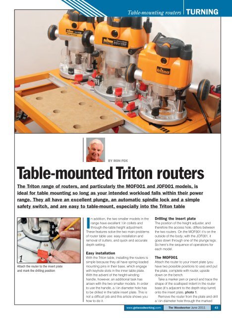
The <strong>Triton</strong> range of routers, and particularly the MOF001 and JOF001 models, is<br />
ideal for table mounting so long as your intended workload falls within their power<br />
range. They all have an excellent plunge, an automatic spindle lock and a simple<br />
safety switch, and are easy to table-mount, especially into the <strong>Triton</strong> table<br />
1<br />
Attach the router to the insert plate<br />
and mark the drilling position<br />
In addition, the two smaller models in the<br />
range have excellent 1 ⁄2in collets and<br />
through-the-table height adjustment.<br />
These features solve the two main problems<br />
of router table use: easy installation and<br />
removal of cutters, and quick and accurate<br />
depth setting.<br />
Easy installation<br />
With the <strong>Triton</strong> table, installing the routers is<br />
simple because they all have spring-loaded<br />
mounting pins in their base, which engage<br />
with keyhole slots in the inner table plate.<br />
With the advent of the height-winding<br />
handle, however, an additional task has<br />
arisen with the two smaller models. In order<br />
to use the handle, a 1 ⁄2in diameter hole has<br />
to be drilled in the table insert plate. This is<br />
not a diffi cult job and this article shows you<br />
how to do it.<br />
Drilling the insert plate<br />
The position of the height adjuster, and<br />
therefore the access hole, differs between<br />
the two routers. On the MOF001 it’s on the<br />
outside of the body; with the JOF001, it<br />
goes down through one of the plunge legs.<br />
So here’s the sequence of operations for<br />
each model.<br />
The MOF001<br />
Attach the router to your insert plate (you<br />
have two possible positions to use) and put<br />
the plate, complete with router, upside<br />
down on the bench.<br />
Take a marker pen or pencil and trace the<br />
shape of the scalloped indent in the router<br />
base (it’s adjacent to the depth stop turret)<br />
onto the insert plate, photo 1.<br />
Remove the router from the plate and drill<br />
a 1 ⁄2in diameter hole through the marked<br />
www.getwoodworking.com<br />
The Woodworker June 2011<br />
43
I WORKSHOP Table-mounting routers<br />
2 3 4 5<br />
Clamp the plate securely and drill a<br />
12mm diameter hole through it<br />
Remove any burrs from the top and<br />
bottom surfaces of the plate<br />
Reattach the router to the plate<br />
and check the hole’s alignment<br />
Drop the winding handle into place<br />
and engage it with the router<br />
6 7 8<br />
Mark the position of the winding hole on the<br />
edge of the sole plate<br />
Place the sole plate on the insert plate<br />
and mark the hole position<br />
Changing cutters is now child’s play,<br />
especially with a cranked spanner<br />
9<br />
The system is particularly useful for setting<br />
critical cutting depths<br />
THE TRITON 2000W ROUTER<br />
The original <strong>Triton</strong> router has the quick-fi t pins, deep plunge and automatic spindle lock<br />
but not the through-the-table height setting, so the need to drill an access hole for a<br />
winding handle doesn’t arise. The router is mounted onto the <strong>Triton</strong> insert plate via the<br />
pins in the keyhole slots, and to other plates using the method described above.<br />
The system works well, but the universal clamping system is so good and so easy to<br />
operate that I use it as well as the keyhole slots with the <strong>Triton</strong> routers to give extra<br />
support, especially with the heavier 2000W model.<br />
circle, photo 2. You might like to use a<br />
smaller diameter pilot bit to drill a starter<br />
hole before using the 1 ⁄2in bit.<br />
Remove any burrs left on the top and<br />
bottom edges of the hole. I used a<br />
de-burring stone in a power drill, photo 3,<br />
but a small round hand fi le is as effective.<br />
Refi t the router to the plate, photo 4; the<br />
drilled hole should line up exactly with the<br />
scalloped indent used to mark its position.<br />
Drop the end of the winding handle through<br />
the hole and engage it with the protruding<br />
rod on the router, photo 5. If the hole is<br />
slightly off-centre, enlarge it with a round fi le<br />
then install the insert plate in the table.<br />
The JOF001<br />
The only procedural difference between this<br />
router and the MOF001 is the marking of<br />
the position of the hole on the insert plate.<br />
Mark the edge of the plastic sole plate<br />
adjacent to the winding hole, attach the<br />
router to the insert plate and mark its<br />
position, photo 6. Remove the router from<br />
the insert plate and detach the sole plate<br />
from the router, then place the sole plate<br />
over the marked position on the insert plate,<br />
and mark the position of the cut through the<br />
hole in the sole plate, photo 7. Lift the sole<br />
plate aside and drill the 1 ⁄2in diameter hole in<br />
the insert plate as before, then remove any<br />
burrs from the edges of the hole.<br />
Reattach the sole plate to the router, refi t<br />
the router to the insert plate and insert the<br />
winding handle down through the plunge<br />
leg. As before, if the hole is slightly<br />
off-centre, enlarge it with a round fi le. Install<br />
the plate in the table and start routing.<br />
Using the system.<br />
With either of these routers mounted in the<br />
table, plunging to full depth will<br />
automatically lock the spindle when you<br />
rotate the collet. Note that this works only if<br />
the router switch is off. If you just switch off<br />
at the NVR switch or the wall socket, the<br />
router can’t be plunged deep enough to<br />
engage the lock. Cutter changing is now<br />
child’s play, since the spindle is locked and<br />
the collet is above the surface of the table.<br />
A cranked spanner makes the job even<br />
easier, photo 8.<br />
With the cutter installed, you can carry<br />
out precise depth setting by dropping the<br />
winding handle through the hole you have<br />
drilled and engaging it with the router<br />
adjuster. The system is particularly useful for<br />
setting critical depths of cut on work such<br />
as the scribed rails on frame-and-panel<br />
constructions, photo 9.<br />
FURTHER INFORMATION<br />
■ <strong>Triton</strong> <strong>Tools</strong><br />
■ 08<strong>44</strong> 576 0266<br />
■ www.tritontools<br />
<strong>44</strong> The Woodworker June 2011 www.getwoodworking.com