

AD7714* 3 V/5 V, CMOS, 500 µA Signal Conditioning ADC - dreamm
AD7714* 3 V/5 V, CMOS, 500 µA Signal Conditioning ADC - dreamm
AD7714* 3 V/5 V, CMOS, 500 µA Signal Conditioning ADC - dreamm

Create successful ePaper yourself
Turn your PDF publications into a flip-book with our unique Google optimized e-Paper software.
AD7714<br />
APPLICATIONS<br />
The on-chip PGA allows the AD7714 to handle an analog input<br />
voltage range as low as 10 mV full-scale with V REF = +1.25 V.<br />
The differential inputs of the part allow this analog input range<br />
to have an absolute value anywhere between AGND and AV DD<br />
when the part is operated in unbuffered mode. It allows the user<br />
to connect the transducer directly to the input of the AD7714.<br />
The programmable gain front end on the AD7714 allows the<br />
part to handle unipolar analog input ranges from 0 mV to<br />
+20 mV to 0 V to +2.5 V and bipolar inputs of ±20 mV to<br />
±2.5 V. Because the part operates from a single supply these<br />
bipolar ranges are with respect to a biased-up differential input.<br />
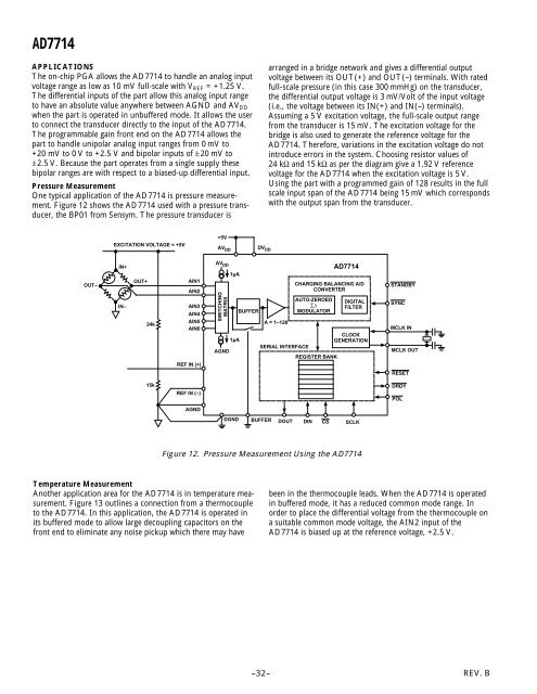
Pressure Measurement<br />
One typical application of the AD7714 is pressure measurement.<br />
Figure 12 shows the AD7714 used with a pressure transducer,<br />
the BP01 from Sensym. The pressure transducer is<br />
arranged in a bridge network and gives a differential output<br />
voltage between its OUT(+) and OUT(–) terminals. With rated<br />
full-scale pressure (in this case 300 mmHg) on the transducer,<br />
the differential output voltage is 3 mV/Volt of the input voltage<br />
(i.e., the voltage between its IN(+) and IN(–) terminals).<br />
Assuming a 5 V excitation voltage, the full-scale output range<br />
from the transducer is 15 mV. The excitation voltage for the<br />
bridge is also used to generate the reference voltage for the<br />
AD7714. Therefore, variations in the excitation voltage do not<br />
introduce errors in the system. Choosing resistor values of<br />
24 kΩ and 15 kΩ as per the diagram give a 1.92 V reference<br />
voltage for the AD7714 when the excitation voltage is 5 V.<br />
Using the part with a programmed gain of 128 results in the full<br />
scale input span of the AD7714 being 15 mV which corresponds<br />
with the output span from the transducer.<br />
EXCITATION VOLTAGE = +5V<br />
+5V<br />
AV DD<br />
DV DD<br />
IN+<br />
AV DD<br />
1µA<br />
AD7714<br />
OUT–<br />
IN–<br />
OUT+<br />
24k<br />
AIN1<br />
AIN2<br />
AIN3<br />
AIN4<br />
AIN5<br />
AIN6<br />
REF IN (+)<br />
SWITCHING<br />
MATRIX<br />
AGND<br />
1µA<br />
BUFFER<br />
A = 1–128<br />
SERIAL INTERFACE<br />
CHARGING BALANCING A/D<br />
CONVERTER<br />
AUTO-ZEROED<br />
∑∆<br />
MODULATOR<br />
REGISTER BANK<br />
DIGITAL<br />
FILTER<br />
CLOCK<br />
GENERATION<br />
STANDBY<br />
SYNC<br />
MCLK IN<br />
MCLK OUT<br />
RESET<br />
15k<br />
REF IN (–)<br />
DRDY<br />
POL<br />
AGND<br />
DGND BUFFER DOUT DIN CS SCLK<br />
Figure 12. Pressure Measurement Using the AD7714<br />
Temperature Measurement<br />
Another application area for the AD7714 is in temperature measurement.<br />
Figure 13 outlines a connection from a thermocouple<br />
to the AD7714. In this application, the AD7714 is operated in<br />
its buffered mode to allow large decoupling capacitors on the<br />
front end to eliminate any noise pickup which there may have<br />
been in the thermocouple leads. When the AD7714 is operated<br />
in buffered mode, it has a reduced common mode range. In<br />
order to place the differential voltage from the thermocouple on<br />
a suitable common mode voltage, the AIN2 input of the<br />
AD7714 is biased up at the reference voltage, +2.5 V.<br />
–32–<br />
REV. B


