SERVICE MANUAL FOR M35&36; CHASSIS
SERVICE MANUAL FOR M35&36; CHASSIS SERVICE MANUAL FOR M35&36; CHASSIS
TCL Chassis M35&36 Service Manual OPERATING DESCRIPTION Regulation The pin 3 senses the feedback current provided by the opto-coupler. During the switching phase the switch S2 is closed and the shunt regulator is accessible by the pin 3. The shunt regulator voltage is typically 5V. The dynamic resistance of the shunt regulator represented by the zener diode is 20 . The gain of the Control input is given on Figure 10 which shows the duty cycle as a function of the current injected into the pin 3. The maximum current sense threshold is fixed at 1V. The peak A 4KHz filter network is inserted between the shunt regulator and the PWM comparator to cancel the high frequency residual noise. The switch S3 is closed in Stand–by mode during the Latched Off Phase while the switch S2 remains open. (See section PULSED MODE DUTY CYCLE CONTROL). The resistor Rdpulsed (Rduty cycle burst) has no effect on the regulation process. This resistor is used to determine the burst duty cycle. PWM Latch The MC44608 works in voltage mode. The on–time is controlled by the PWM comparator that compares the oscillator sawtooth with the regulation block output. The PWM latch is initialized by the oscillator and is reset by the PWM comparator or by the current sense comparator in case of an over current. This configuration ensures that only a single pulse appears at the circuit output during an oscillator cycle. Current Sense The inductor current is converted to a positive voltage by inserting a ground reference sense resistor RSense in series with the power switch. The maximum current sense threshold is fixed at 1V. The peak current is given by the following equation: Ipkmax = 1/Rsense( ) (A) In stand–by mode, this current can be lowered as due to the activation of a 200 A current source: IpkMAX-STBY The current sense input consists of a filter (6k , 4pF) and of a leading edge blanking. Thanks to that, this pin is not sensitive to the power switch turn on noise and spikes and practically in most applications, no filtering network is required to sense the current. Finally, this pin is used: 8 03.Mar.2003
TCL – as a protection against over currents (Isense > I) – as a reduction of the peak current during a Pulsed Mode switching phase. Chassis M35&36 Service Manual The overcurrent propagation delay is reduced by producing a sharp output turn off (high slew rate). This results in an abrupt output turn off in the event of an over current and in the majority of the pulsed mode switching sequence. Demagnetization Section The MC44608 demagnetization detection consists of a comparator designed to compare the VCC winding voltage to a reference that is typically equal to 50mV. This reference is chosen low to increase effectiveness of the demagnetization detection even during start–up. A latch is incorporated to turn the demagnetization block output into a low level as soon as a voltage less than 50 mV is detected, and to keep it in this state until a new pulse is generated on the output. This avoids any ringing on the input signal which may alter the demagnetization detection. For a higher safety, the demagnetization block output is also directly connected to the output, which is disabled during the demagnetization phase. The demagnetization pin is also used for the quick programmable OVP. In fact, the demagnetization input current is sensed so that the circuit output is latched off when this current is detected as higher than 120 A. This function can be inhibited by grounding it but in this case, the quick and programmable OVP is also disabled. Oscillator The MC44608 contains a fixed frequency oscillator. It is built around a fixed value capacitor CT succesively charged and discharged by two distinct current sources ICH and IDCH. The window comparator senses the CT voltage value and activates the sources when the voltage is reaching the 2.4V/4V levels. 9 03.Mar.2003
- Page 1 and 2: TCL Chassis M35&36 Service Manual S
- Page 3 and 4: TCL [Treble, Bass, Balance Control
- Page 5 and 6: TCL Chassis M35&36 Service Manual S
- Page 7: TCL PART IV. IC Pin Description 1.
- Page 11 and 12: TCL Chassis M35&36 Service Manual v
- Page 13 and 14: TCL Chassis M35&36 Service Manual P
- Page 15 and 16: TCL Chassis M35&36 Service Manual N
- Page 17 and 18: TCL Chassis M35&36 Service Manual A
- Page 19 and 20: TCL Chassis M35&36 Service Manual N
- Page 21 and 22: TCL 6. TDA7057AQ Audio Output Ampli
- Page 23 and 24: TCL APPLICATION DIAGRAM Chassis M35
- Page 25 and 26: TCL Chassis M35&36 Service Manual 7
- Page 27 and 28: TCL Signal flow block diagram (inpu
- Page 29 and 30: TCL Chassis M35&36 Service Manual T
- Page 31 and 32: TCL decay time: 37 ms Chassis M35&3
- Page 33 and 34: TCL (Fig. 9) Word strobe line for t
- Page 35 and 36: TCL Pin Circuits Pin No. Pin Name T
- Page 37 and 38: TCL Chassis M35&36 Service Manual P
- Page 39 and 40: TCL Chip Architecture Chassis M35&3
- Page 41 and 42: TCL Pin Connections and Short Descr
- Page 43 and 44: TCL operation, it must be connected
- Page 45 and 46: TCL Pin 59, SCL . I2C Bus Clock (Fi
- Page 47 and 48: TCL Chassis M35&36 Service Manual P
- Page 49 and 50: TCL Chassis M35&36 Service Manual 3
- Page 51 and 52: TCL c. Press [V-] to make the Addre
- Page 53 and 54: TCL Chassis M35&36 Service Manual N
- Page 55 and 56: TCL Chassis M35&36 Service Manual C
- Page 57 and 58: TCL Chassis M35&36 Service Manual O
TCL<br />
– as a protection against over currents (Isense > I)<br />
– as a reduction of the peak current during a Pulsed Mode switching phase.<br />
Chassis M35&<strong>36</strong> Service Manual<br />
The overcurrent propagation delay is reduced by producing a sharp output turn off (high slew rate).<br />
This results in an abrupt output turn off in the event of an over current and in the majority of the pulsed<br />
mode switching sequence.<br />
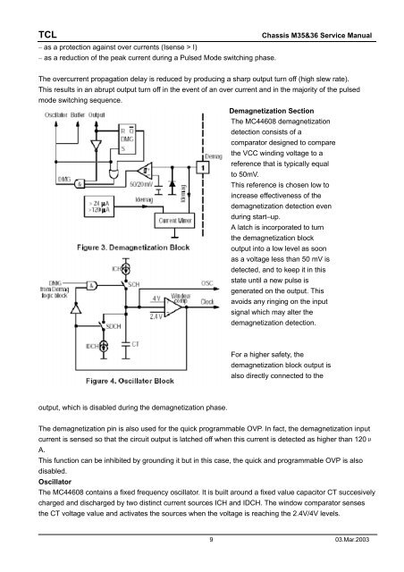
Demagnetization Section<br />
The MC44608 demagnetization<br />
detection consists of a<br />
comparator designed to compare<br />
the VCC winding voltage to a<br />
reference that is typically equal<br />
to 50mV.<br />
This reference is chosen low to<br />
increase effectiveness of the<br />
demagnetization detection even<br />
during start–up.<br />
A latch is incorporated to turn<br />
the demagnetization block<br />
output into a low level as soon<br />
as a voltage less than 50 mV is<br />
detected, and to keep it in this<br />
state until a new pulse is<br />
generated on the output. This<br />
avoids any ringing on the input<br />
signal which may alter the<br />
demagnetization detection.<br />
For a higher safety, the<br />
demagnetization block output is<br />
also directly connected to the<br />
output, which is disabled during the demagnetization phase.<br />
The demagnetization pin is also used for the quick programmable OVP. In fact, the demagnetization input<br />
current is sensed so that the circuit output is latched off when this current is detected as higher than 120<br />
A.<br />
This function can be inhibited by grounding it but in this case, the quick and programmable OVP is also<br />
disabled.<br />
Oscillator<br />
The MC44608 contains a fixed frequency oscillator. It is built around a fixed value capacitor CT succesively<br />
charged and discharged by two distinct current sources ICH and IDCH. The window comparator senses<br />
the CT voltage value and activates the sources when the voltage is reaching the 2.4V/4V levels.<br />
9 03.Mar.2003


