SERVICE MANUAL FOR M35&36; CHASSIS
SERVICE MANUAL FOR M35&36; CHASSIS SERVICE MANUAL FOR M35&36; CHASSIS
TCL Chassis M35&36 Service Manual 1.2.5. Manual Mode Below Fig. shows the source channel assignment of demodulated signals in case of manual mode. 1.3. Preprocessing for SCART and I 2 S Input Signals The SCART and I 2 S inputs need only be adjusted in level by means of the SCART and I 2 S prescale registers. 1.4. Source Selection and Output Channel Matrix The Source Selector makes it possible to distribute all source signals (one of the demodulator source channels or SCART) to the desired output channels (loudspeaker, etc.). All input and output signals can be processed simultaneously. Each source channel is identified by a unique source address. For each output channel, the sound mode can be set to sound A, sound B, stereo, or mono by means of the output channel matrix. If Automatic Sound Select is on, the output channel matrix can stay fixed to stereo (transparent) for demodulated signals. 1.5. Audio Baseband Processing 1.5.1. Automatic Volume Correction (AVC) Different sound sources (e.g. terrestrial channels, SAT channels, or SCART) fairly often do not have the same volume level. Advertisements during movies usually have a higher volume level than the movie itself. This results in annoying volume changes. The AVC solves this problem by equalizing the volume level. To prevent clipping, the AVC’s gain decreases quickly in dynamic boost conditions. To suppress oscillation effects, the gain increases rather slowly for low level inputs. The decay time is programmable by means of the AVC register . For input signals ranging from .24 dBr to 0 dBr, the AVC maintains a fixed output level of .18 dBr. Below Fig. shows the AVC output level versus its input level. For prescale and volume registers set to 0 dB, a level of 0 dBr corresponds to full scale input/output. This is – SCART input/output 0 dBr = 2.0 Vrms – Loudspeaker output 0 dBr = 1.4 Vrms 1.5.2. Loudspeaker Outputs The following baseband features are implemented in the loudspeaker output channels: bass/treble, loudness, balance, and volume. A square wave beeper can be added to the loudspeaker channel. 1.5.3. Quasi-Peak Detector Simplified AVC characteristics The quasi-peak readout register can be used to readout the quasi-peak level of any input source. The feature is based on following filter time constants: attack time: 1.3 ms 30 03.Mar.2003
TCL decay time: 37 ms Chassis M35&36 Service Manual 1.6. SCART Signal Routing 1.6.1. SCART DSP In and SCART Out Select The SCART DSP Input Select and SCART Output Select blocks include full matrix switching facilities. To design a TV set with two pairs of SCART-inputs and one pair of SCART-outputs, no external switching hardware is required. The switches are controlled by the ACB user register. 1.6.2. Stand-by Mode If the MSP 34x5G is switched off by first pulling STANDBYQ low and then (after >1⎧s delay) switching off DVSUP and AVSUP, but keeping AHVSUP (‘Stand-by’-mode), the SCART switches maintain their position and function. This allows the copying from selected SCART-inputs to SCART-outputs in the TV set’s stand-by mode. In case of power on or starting from stand-by (switching on the DVSUP and AVSUP, RESETQ going high 2 ms later), all internal registers except the ACB register are reset to the default configuration .The reset position of the ACB register becomes active after the first I 2 C transmission into the Baseband Processing part. By transmitting the ACB register first, the reset state can be redefined. Pin Connections and Short Descriptions NC = not connected; leave vacant LV = if not used, leave vacant DVSS: if not used, connect to DVSS X = obligatory; connect as described in circuit diagram AHVSS: connect to AHVSS No. Pin Name Pin No. Type Connection (if not used) Short Description 1 TP 1 LV Test pin 2 NC 2 LV Not connected 3 D_CTR_I/O_1 3 IN/OUT LV D_CTR_I/O_1 4 D_CTR_I/O_0 4 IN/OUT LV D_CTR_I/O_0 5 ADR_SEL 5 IN X I 2 C Bus address select 6 STANDBYQ 6 IN X Standby (low-active) 7 I2C_CL 7 IN/OUT X I 2 C clock 8 I2C_DA 8 IN/OUT X I 2 C data 9 I2C_CL 9 LV I 2 C clock 10 I2C_WS 10 LV I 2 C word strobe 11 I2C_DA_OUT 11 LV I 2 C data output 12 I2C_DA_IN1 12 LV I 2 C data input 13 ADR_DA 13 LV ADR data output 14 ADR_WS 14 LV ADR word strobe 15 ADR_CL 15 LV ADR clock 16 DVSUP 16 X Digital power supply +5V 17 DVSS 17 X Digital ground 18 I2C_DA_IN2 18 LV I 2 C2-data input 19 NC 19 LV Not connected 20 RESETQ 20 IN X Power-on-reset 21 NC 21 LV Not connected 22 NC 22 LV Not connected 23 VREF2 23 X Reference ground 2 high-voltage part 24 DACM_R 24 OUT LV Loudspeaker out, right 25 DACM_L 25 OUT LV Loudspeaker out, left 26 NC 26 LV Not connected 27 NC 27 LV Not connected 28 NC 28 LV Not connected 31 03.Mar.2003
- Page 1 and 2: TCL Chassis M35&36 Service Manual S
- Page 3 and 4: TCL [Treble, Bass, Balance Control
- Page 5 and 6: TCL Chassis M35&36 Service Manual S
- Page 7 and 8: TCL PART IV. IC Pin Description 1.
- Page 9 and 10: TCL - as a protection against over
- Page 11 and 12: TCL Chassis M35&36 Service Manual v
- Page 13 and 14: TCL Chassis M35&36 Service Manual P
- Page 15 and 16: TCL Chassis M35&36 Service Manual N
- Page 17 and 18: TCL Chassis M35&36 Service Manual A
- Page 19 and 20: TCL Chassis M35&36 Service Manual N
- Page 21 and 22: TCL 6. TDA7057AQ Audio Output Ampli
- Page 23 and 24: TCL APPLICATION DIAGRAM Chassis M35
- Page 25 and 26: TCL Chassis M35&36 Service Manual 7
- Page 27 and 28: TCL Signal flow block diagram (inpu
- Page 29: TCL Chassis M35&36 Service Manual T
- Page 33 and 34: TCL (Fig. 9) Word strobe line for t
- Page 35 and 36: TCL Pin Circuits Pin No. Pin Name T
- Page 37 and 38: TCL Chassis M35&36 Service Manual P
- Page 39 and 40: TCL Chip Architecture Chassis M35&3
- Page 41 and 42: TCL Pin Connections and Short Descr
- Page 43 and 44: TCL operation, it must be connected
- Page 45 and 46: TCL Pin 59, SCL . I2C Bus Clock (Fi
- Page 47 and 48: TCL Chassis M35&36 Service Manual P
- Page 49 and 50: TCL Chassis M35&36 Service Manual 3
- Page 51 and 52: TCL c. Press [V-] to make the Addre
- Page 53 and 54: TCL Chassis M35&36 Service Manual N
- Page 55 and 56: TCL Chassis M35&36 Service Manual C
- Page 57 and 58: TCL Chassis M35&36 Service Manual O
- Page 59 and 60: TCL Chassis M35&36 Service Manual P
- Page 61 and 62: TCL Chassis M35&36 Service Manual 1
- Page 63 and 64: TCL Chassis M35&36 Service Manual 1
- Page 65 and 66: TCL Chassis M35&36 Service Manual 2
- Page 67 and 68: TCL Chassis M35&36 Service Manual 4
- Page 69 and 70: TCL Chassis M35&36 Service Manual 1
- Page 71 and 72: TCL Chassis M35&36 Service Manual 2
- Page 73 and 74: TCL Chassis M35&36 Service Manual S
- Page 75 and 76: TCL Chassis M35&36 Service Manual 5
- Page 77 and 78: TCL Chassis M35&36 Service Manual 1
- Page 79 and 80: TCL Chassis M35&36 Service Manual 2
TCL<br />
Chassis M35&<strong>36</strong> Service Manual<br />
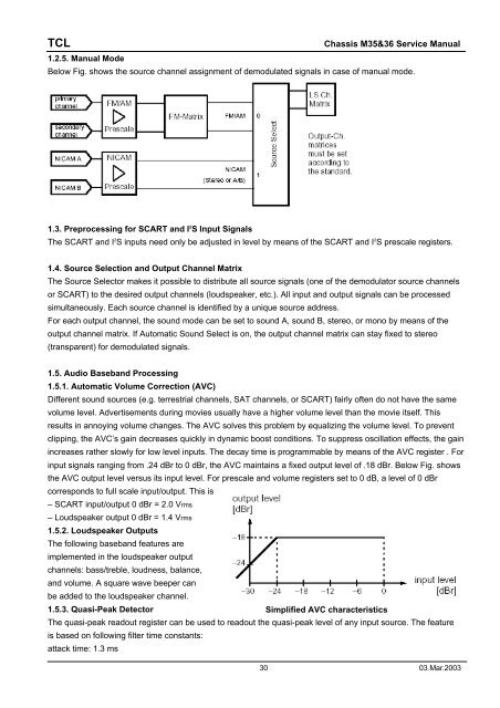
1.2.5. Manual Mode<br />
Below Fig. shows the source channel assignment of demodulated signals in case of manual mode.<br />
1.3. Preprocessing for SCART and I 2 S Input Signals<br />
The SCART and I 2 S inputs need only be adjusted in level by means of the SCART and I 2 S prescale registers.<br />
1.4. Source Selection and Output Channel Matrix<br />
The Source Selector makes it possible to distribute all source signals (one of the demodulator source channels<br />
or SCART) to the desired output channels (loudspeaker, etc.). All input and output signals can be processed<br />
simultaneously. Each source channel is identified by a unique source address.<br />
For each output channel, the sound mode can be set to sound A, sound B, stereo, or mono by means of the<br />
output channel matrix. If Automatic Sound Select is on, the output channel matrix can stay fixed to stereo<br />
(transparent) for demodulated signals.<br />
1.5. Audio Baseband Processing<br />
1.5.1. Automatic Volume Correction (AVC)<br />
Different sound sources (e.g. terrestrial channels, SAT channels, or SCART) fairly often do not have the same<br />
volume level. Advertisements during movies usually have a higher volume level than the movie itself. This<br />
results in annoying volume changes. The AVC solves this problem by equalizing the volume level. To prevent<br />
clipping, the AVC’s gain decreases quickly in dynamic boost conditions. To suppress oscillation effects, the gain<br />
increases rather slowly for low level inputs. The decay time is programmable by means of the AVC register . For<br />
input signals ranging from .24 dBr to 0 dBr, the AVC maintains a fixed output level of .18 dBr. Below Fig. shows<br />
the AVC output level versus its input level. For prescale and volume registers set to 0 dB, a level of 0 dBr<br />
corresponds to full scale input/output. This is<br />
– SCART input/output 0 dBr = 2.0 Vrms<br />
– Loudspeaker output 0 dBr = 1.4 Vrms<br />
1.5.2. Loudspeaker Outputs<br />
The following baseband features are<br />
implemented in the loudspeaker output<br />
channels: bass/treble, loudness, balance,<br />
and volume. A square wave beeper can<br />
be added to the loudspeaker channel.<br />
1.5.3. Quasi-Peak Detector<br />
Simplified AVC characteristics<br />
The quasi-peak readout register can be used to readout the quasi-peak level of any input source. The feature<br />
is based on following filter time constants:<br />
attack time: 1.3 ms<br />
30 03.Mar.2003


