SERVICE MANUAL FOR M35&36; CHASSIS
SERVICE MANUAL FOR M35&36; CHASSIS
SERVICE MANUAL FOR M35&36; CHASSIS

Create successful ePaper yourself
Turn your PDF publications into a flip-book with our unique Google optimized e-Paper software.
TCL<br />
Chassis M35&<strong>36</strong> Service Manual<br />
Pulsed Mode Duty Cycle Control<br />
During the sleep mode of the SMPS the switch S3 is closed and the control input pin 3 is connected to a<br />
4.6V voltage source thru a 500 resistor. The discharge rate of the VCC capacitor is given by ICC–latch<br />
(device consumption during the LATCHED OFF phase) in addition to the current drawn out of the pin 3.<br />
Connecting a resistor between the Pin 3 and GND (RDPULSED) a programmable current is drawn from<br />
the VCC through pin 3. The duration of the LATCHED OFF phase is impacted by the presence of the<br />
resistor RDPULSED. The equation 3 shows the relation to the pin 3 current.<br />
Pulsed Mode Phases<br />
Equations 1 through 8 define and predict the effective behavior during the PULSED MODE operation. The<br />
equations 6, 7, and 8 contain K, Y, and D factors. These factors are combinations of measured parameters.<br />
They appear in the parameter section “K factors for pulsed mode operation”. In equations 3 through 8 the<br />
pin 3 current is the current defined in the above section “Pulsed Mode Duty Cycle Control”.<br />
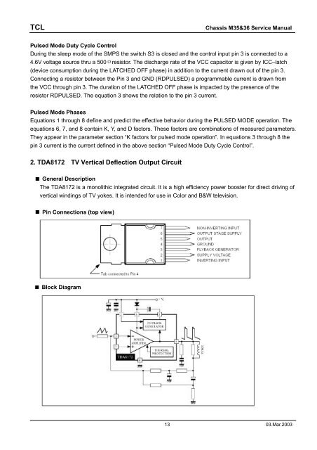
2. TDA8172 TV Vertical Deflection Output Circuit<br />
General Description<br />
The TDA8172 is a monolithic integrated circuit. It is a high efficiency power booster for direct driving of<br />
vertical windings of TV yokes. It is intended for use in Color and B&W television.<br />
Pin Connections (top view)<br />
Block Diagram<br />
13 03.Mar.2003