You also want an ePaper? Increase the reach of your titles
YUMPU automatically turns print PDFs into web optimized ePapers that Google loves.
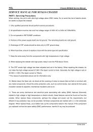
Important <strong>Service</strong> Notes<br />
1. X-ray Radiation Rrecaution<br />
1) Excessive high voltage can produce potentially hazardous X-RAY RADIA-<br />
TION. To avoid such hazards, the high voltage must not be above the specified<br />
limit. The nominal value of the high voltage of this receiver is<br />
25.5kv(20”/21”) & 23.5kv(14”)at zero beam current (minimum brightness)<br />
under a 120V/220V AC power source. The high voltage must not, under any<br />
circumstances, exceed 28kv(20”/21”) & 26kv(14”). Each time a receiver<br />
requires servicing, the high voltage should be checked following the HIGH<br />
VOLTAGE CHECK procedure on page 10 of this manual. It is recommended<br />
as a parts of the service record. It is important to use an accurate<br />
and reliable high voltage meter.<br />
2) This receiver is equipped with X-RADIATION PROTECTION circuit which<br />
prevents the receiver from producing an excessively high voltage even if the<br />
B+voltage increases abnormally. Each time the receiver is serviced, X-<br />
RADIATION PROTECTION circuit must be checked to determine that the<br />
circuit is properly functioning, following the X-RADIATION PROTECTION<br />
CIRCUIT CHECK procedure on page 6 of this manual.<br />
3) The only source of X-RAY RADIATION in this TV receiver is the picture tube.<br />
For continued X-RAY RADIATION protection, the replacement tube must be<br />
exactly the same type tube as specified in the parts list.<br />
4) Some parts in this receiver have special safety-related characteristics for X-<br />
RAY RADIATION protection. For continued safety, parts replacement<br />
should be undertaken only after referring to the PRODUCT SAFETY<br />
NOTICE below.<br />
2. Safety Precaution<br />
WARNING: <strong>Service</strong> should not be attempted by anyone unfamiliar with the<br />
necessary precaution on this receiver. The following are the necessary precaution<br />
to be observed before servicing.<br />
1) Since the chassis of this receiver has hazardous potential to ground whenever<br />
the receiver is plugged in (floating chassis), an isolation transformer<br />
must be used during servicing to avoid shock hazard.<br />
2) Always discharge the picture tube anode to the CRT conductive coating the<br />
picture tube. The picture tube is highly evacuated and if broken, glass fragments<br />
will be violently expelled. Use shatterproof goggles and keep picture<br />
tube away from the body while handling.<br />
3) When placing chassis in the cabinet, always be certain that all the protective<br />
devices are put back in place, such as; nonmetallic control knobs, insulating<br />
covers, shields, isolation resistor-capacitor network, etc.<br />
4) Before returning the set to the customer, always perform an AC leakage current<br />
check on the exposed metallic parts of the cabinet, such as antennas,<br />
terminals, screw-heads, metal overlays, control shafts etc. to be sure the set<br />
is safe to operate without danger of electrical shock. Plug the AC line cord<br />
directly into a 120V AC outlet (do not use a line isolation transformer during<br />
this check). Use an AC voltmeter having 5000 ohms per volt or more sensitivi-ty<br />
in the following manner.<br />
Connect at 1500 ohm 10 watt resistor, paralleled by a 0.15 mfd. AC type<br />
capacitor, between a known good earth ground (water pipe, conduit etc.)<br />
and the exposed metallic parts, one at a time. Measure the AC voltage<br />
across the combination of 1500 ohm resistor and 0.15 mfd capacitor. Voltage<br />
measured must not exceed 0.3 volts RMS. This corresponds to 0.2 millliamp.<br />
AC. Any value exceeding the limit constitutes a potential shock<br />
hazard and must be corrected immediately.<br />
3. Product Safety Notice<br />
Many electrical and mechanical parts in this chassis have special safety-related<br />
characteristics. These characteristics are often passed unnoticed by a visual<br />
inspection and the protection afforded by them cannot necessarily be obtained<br />
by using replacement components rated for higher voltage, wattage, etc.<br />
Replacement parts which have these special safety characteristics are identified<br />
in this manual and its supplements; electrical components having such features<br />
are identified by shading on the schematic diagram and the parts list.<br />
Before replacing any of these components, read the parts list in this manual<br />
carefully. The use of substitute replacement parts which do not have the same<br />
safety characteristics as specified in the parts list may create X-ray radiation or<br />
other hazards.<br />
Good earth ground<br />
such as d water<br />
pipe, conduit, etc.<br />
4. <strong>Service</strong> Notes<br />
1) When replacing parts or circuit boards, clamp or bend the lead wires to terminals<br />
before soldering.<br />
AC VOLT METER<br />
0.15uF<br />
1500 OHM<br />
10WATT<br />
Place this probe<br />
on each exposed<br />
metallic part.<br />
2) When replacing a high wattage resistor (metal oxide film resistor) in the circuit<br />
board, keep the resistor min 1/2 inch away form circuit board.<br />
3) Keep wires away from high voltage or high temperature components.<br />
DAEWOO ELECTRONICS CO., LTD.<br />
C.P.OBOX8003 SEOUL, KOREA<br />
Tel : 82-2-360-7798<br />
Fax : 82-2-360-7877<br />
E-mail : G7F00E@dwe.web.co.kr<br />
Printed in Apr. 2000