You also want an ePaper? Increase the reach of your titles
YUMPU automatically turns print PDFs into web optimized ePapers that Google loves.
CANCELLI AUTOMATICI<br />
SERIE Z | Z SERIES | SÉRIE Z | BAUREIHE Z | SERIE Z<br />
QUADRO COMANDO<br />
ELECTRIC CONTROL PANEL<br />
ARMOIRE DE COMMANDE<br />
SCHALTTAFEL<br />
CUADRO DE MANDO<br />
<strong>ZT4</strong><br />
Documentazione<br />
Tecnica<br />
S12<br />
rev. 2.2<br />
10/2001<br />
© CAME<br />
CANCELLI<br />
AUTOMATICI<br />
319S12<br />
320 mm<br />
120 mm<br />
240 mm<br />
145 mm<br />
ITALIANO<br />
CARATTERISTICHE GENERALI<br />
Descrizione quadro comando<br />
Quadro elettrico per motoriduttori con<br />
alimentazione 230V monofase o 400V<br />
trifase; frequenza 50÷60 Hz.<br />
Progettato e costruito interamente dalla<br />
CAME S.p.A., risponde alle vigenti<br />
norme di sicurezza UNI 8612, con<br />
grado di protezione IP 54. Scatola in<br />
ABS, dotata di presa per il riciclo d'aria.<br />
Garantito 12 mesi salvo manomissioni.<br />
Il circuito va alimentato sui morsetti R,<br />
S e T (con alimentazione a 400V trifase)<br />
oppure solo sui morsetti R e S (con<br />
alimentazione a 230V monofase),<br />
protetto in ingresso con fusibili da 8A.<br />
Il quadro comando <strong>ZT4</strong> è predisposto<br />
per l'alimentazione a 400V. Nel caso di<br />
alimentazione a 230V spostare il<br />
collegamento che cortocircuita i morsetti<br />
«380» e «COM» sui morsetti «220»<br />
e«COM» (vedi pag.12).
ENGLISH<br />
GENERAL CHARACTERISTICS<br />
Description of control panel<br />
Control panel for gear motors, powered<br />
by 230V single-phase or 400V threephase;<br />
frequency 50-60 Hz.<br />
Designed and built entirely by CAME to<br />
meet UNI 8612 safety standards at an<br />
IP 54 level of protection.<br />
Housing in ABS is equipped with vents<br />
to provide internal air circulation.<br />
Guaranteed 12 months, unless<br />
tampered with.<br />
The power supply to the circuit should<br />
be connected to terminals R, S and T<br />
(with three-phase 400V power supply)<br />
or to terminals R and S only (singlephase<br />
230V power supply), is protected<br />
by a 8A fuse on the main power line.<br />
The <strong>ZT4</strong> control panel is factory set for<br />
400V power supply. If the power supply<br />
is 230V, it is necessary to move the<br />
jumper which short-circuit terminals<br />
«380» and «COM» so that it shortcircuits<br />
terminals «220» and «COM»<br />
(see pag.12). The Control systems are<br />
powered by low voltage and protected<br />
with a 2A fuse. The total power<br />
consumption of 24 V accessories must<br />
not exceed 20W.<br />
Fixed operating time of 150 seconds.<br />
Safety<br />
Photocells can be connected to obtain:<br />
-Re-opening during the closing cycle (2-<br />
C1);<br />
-Re-closing during the opening cycle<br />
(2-CX, see dip 8-9);<br />
-Partial stop, shutdown of moving<br />
gate, with activation of an automatic<br />
closing cycle (2-CX, see dip 8-9);<br />
-Total stop (1-2), shutdown of gate<br />
movement without automatic closing;<br />
a pushbutton or radio remote control<br />
must be actuated to resume movement;<br />
N.B: If an NC safety contact (2-C1, 2-<br />
CX, 1-2) is opened, the LED will flash<br />
to indicate this fact;<br />
-Obstacle presence detection. When<br />
the motor is stopped (gate is closed,<br />
open or half-open after an emercency<br />
stop command), the transmitter and<br />
the control pushbutton will be<br />
deactivated if an obstacle is detected<br />
by one of the safety devices (for<br />
example, the photocells);<br />
-Safety test function. The control unit<br />
will now check the safety system<br />
every time an opening or closing<br />
command is given (see pag.14).<br />
Accessories which can be<br />
connected<br />
-Cycle lamp or courtesy light (60<br />
Watt, see pag.16);<br />
Other functions<br />
-Automatic closing: The automatic<br />
closing timer is automatically<br />
activated at the end of the opening<br />
- 4 -
cycle. The preset, adjustable<br />
automatic closing time is automatically<br />
interrupted by the activation of any<br />
safety system, and is deactivated after<br />
a STOP command or in case of power<br />
failure;<br />
-Partial opening. Opening of the gate to<br />
allow for foot traffic; activated by<br />
connecting to terminals 2-3P and<br />
adjusted with the AP-PARZ. trimmer.<br />
With this function, the automatic<br />
closing can vary in the following way:<br />
1) Dip 12 set to ON: after a partial<br />
opening, the time for automatic closing<br />
functions independently of the adjustment<br />
of the TCA trimmer and of the position<br />
of Dip 1; it is set at 8 seconds.<br />
2) Dip 12 set to OFF: after a partial<br />
opening, the time for automatic closing<br />
is adjustable only if Dip 1 is set to ON.<br />
-Cycle lamp. The lamp which lights the<br />
manoeuvring zone: it remains lit from<br />
the moment the doors begin to open<br />
until they are completely closed<br />
(including the time required for the<br />
automatic closure). In case automatic<br />
closure is not enabled, the lamp<br />
remains lit only during movement (E-<br />
EX), see p.16;<br />
-Courtesy Light. A light that illuminates<br />
the manoeuvring zone; after an opening<br />
command, the light remains on for<br />
a fixed time of 5 minutes and 30 seconds<br />
(E-EX), see page 16;<br />
-"Operator present" function: Gate<br />
operates only when the pushbutton is<br />
held down (the radio remote control<br />
system is deactivated);<br />
- Pre-flashing for 5 seconds, while the<br />
door is opening and closing;<br />
- Master function; the panel assumes<br />
all the command functions when two<br />
paired motors are used (see page 30);<br />
- Slave function; this panel is exclusively<br />
controlled by the “MASTER” (see<br />
page 30);<br />
- Enabling functions of partial stop or<br />
re-closure during opening, normallyclosed<br />
contact (2-CX), select one of<br />
the two functions by setting dip (see<br />
selection of functions);<br />
- Type of command:<br />
-open-close-reverse by button and<br />
transmitter;<br />
-open-stop-close-stop by button and<br />
transmitter;<br />
-open only by transmitter.<br />
Adjustments<br />
- Automatic closure time;<br />
- Partial opening time.<br />
Important! Disconnect the unit<br />
from the main power lines before<br />
carrying out any operation inside the<br />
unit.<br />
- 5 -
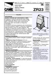
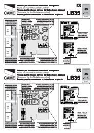
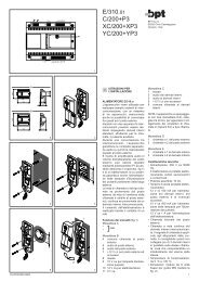
SCHEDA BASE - MOTHERBOARD - CARTE BASE - GRUNDPLATINE - TARJETA BASE<br />
IL QUADRO E’ PREDISPOSTO A 400W<br />
THE BOARD IS PRE-SET TO 400W<br />
LE TABLEAU EST PREVU EN 400W<br />
DIE SCHALTTAFEL IST AUF 400 W AUSGELEGT<br />
EL CUADRO ESTÁ PREAJUSTADO PARA 400W<br />
DIS. 25215<br />
T.C.A.<br />
AP.PARZ.<br />
8<br />
7<br />
2<br />
US.LINEA 5A<br />
USIBILE<br />
ACCESSORI 2A<br />
3<br />
ON<br />
1 2 3 4 5 6 7 8 9 10<br />
ON<br />
11 12 13 14 15 16 17 18 19 20<br />
6<br />
<strong>ZT4</strong><br />
5<br />
CH1<br />
CH2<br />
9<br />
4<br />
AF<br />
1<br />
R S T U V W R<br />
O<br />
S<br />
S<br />
O<br />
230V<br />
B<br />
I<br />
A<br />
N<br />
C<br />
O<br />
B<br />
L<br />
U<br />
3<br />
8<br />
0<br />
2<br />
2<br />
0<br />
C<br />
O<br />
M<br />
Nel caso di alimentazione del quadro comando a 230V,<br />
cortocircuitare i morsetti 220 - COM<br />
Connection for 230V power supply to control panel, shortcircuit<br />
terminals 220 - COM<br />
Dans le cas d'une alimentation de l'armoire de commande<br />
à 230V, court-circuiter les bornes 220 - COM<br />
Im Falle von 230V Stromversorgung des Steuergerätes, die<br />
Klemmen 220 - COM kurzschließen<br />
Caso de que se alimente el cuadro de mando con 230V,<br />
cortocircuitar los bornes 220 - COM<br />
ITALIANO<br />
COMPONENTI PRINCIPALI<br />
1 Morsettiere di collegamento<br />
2 Fusibili di linea 8A<br />
3 Fusibile accessori 2A<br />
4 Innesto scheda radiofrequenza AF (vedi tabella)<br />
5 Pulsanti memorizzazione codice radio<br />
6 Dip-switch "selezione funzioni"<br />
7 Trimmer AP.PARZ.: regolazione apertura parziale<br />
8 Trimmer TCA: regolazione tempo di chiusura automatica<br />
9 LED di segnalazione codice radio<br />
- 12 -
ENGLISH<br />
MAIN COMPONENTS<br />
1 Terminal block for external connections<br />
2 8A line fuse<br />
3 2A accessories fuse<br />
4 Socket AF radiofrequency board (see table)<br />
5 Radio-code save buttons<br />
6 "Function selection" Dip-switch<br />
7 Trimmer AP.PARZ.: Partial opening adjustment<br />
8 Trimmer TCA: automatic closing time adjustment<br />
9 Radio-code LED<br />
FRANÇAIS<br />
COMPOSANTS PRINCIPAUX<br />
1 Plaque à bornes pour les branchements<br />
2 Fusibles de ligne 8A<br />
3 Fusible accessoires 2A<br />
4 Branchement carte radiofréquence AF (voir tableau)<br />
5 Boutons mise en mémoire code radio et programmation<br />
6 Dip-switch "sélection fonction"<br />
7 Trimmer AP.PARZ.: réglage ouverture partielle<br />
8 Trimmer TCA: réglage temps de fermeture automatique<br />
9 LED de segnalisation code radio<br />
DEUTSCH<br />
HAUPTKOMPONENTEN<br />
1 Anschluss-Klemmenleiste<br />
2 8A-Sicherung Leitungs<br />
3 2A-Sicherung Zubehörs<br />
4 Steckanschluß Funkfrequenze-Platine AF (sehen Tabelle)<br />
5 Knöpfe zum Abspeichern der Radiocodes<br />
6 "Funktionswahl" Dip-switch<br />
7 Trimmer AP.PARZ.: Einstellung Teilöffnung<br />
8 Trimmer TCA: Einstellung Zeiteinstellung Schließautomatik<br />
9 LED Kontrolleuchte zur Anzeige von Radiocode<br />
ESPANOL<br />
COMPONENTES PRINCIPALES<br />
1 Caja de bornes para las conexiónes<br />
2 Fusibles de línea 8A<br />
3 Fusible accesorios 2A<br />
4 Conexión tarjeta radiofrecuencia AF (vedas tabla)<br />
5 Botones de memorización del código radio<br />
6 Dip-switch "seleción función"<br />
7 Trimmer AP.PARZ.: regulación apertura parcial<br />
8 Trimmer TCA: regulación cierre automático<br />
9 Indicador luminoso código radio<br />
- 13 -
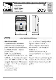
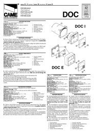
TEST FUNZIONAMENTO FOTOCELLULE / PHOTOCELL FUNCTION TEST<br />
TEST FONCTIONNEMENT PHOTOCELLULES<br />
TEST FÜR DAS FUNKTIONIEREN DER LICHTSCHRANKEN / TEST FUNCIONAMIENTO FOTOCELULAS<br />
FIG. 1<br />
ABB. 1<br />
FIG. 2<br />
ABB. 2<br />
+ - + -<br />
N.O.<br />
C.<br />
N.C.<br />
24V<br />
12V<br />
10 2 TX C NC<br />
TX 2<br />
FUSIBILE 200mA<br />
+ - -<br />
«DOC»<br />
E4 10 11 TS 1 2 3 3P 4 5 6 7 2MOT<br />
«DIR»<br />
E4 10 11 TS 1 2 3 3P 4 5 6 7 2MOT<br />
ITALIANO<br />
ENGLISH<br />
Consente alla centralina di verificare<br />
l'efficenza dei dispositivi di<br />
sicurezza (fotocellule) dopo ogni<br />
comando di apertura o di chiusura.<br />
Un eventuale anomalia delle<br />
fotocellule viene identificata con un<br />
lampeggio del led sul quadro<br />
comando, di conseguenza annulla<br />
qualsiasi funzione del<br />
radiocomando e del pulsante.<br />
Collegamento elettrico per il funzionamento<br />
del test di sicurezza:<br />
I trasmettitori e i ricevitori delle<br />
fotocellule devono essere collegati<br />
come illustrati nelle fig.1 e fig.2.<br />
- selezionare il dip 13 in ON per<br />
attivare il funzionamento del test.<br />
IMPORTANTE: Quando si esegue la<br />
funzione test di sicurezza, VERIFI-<br />
CARE che NON CI SIANO PONTI tra<br />
i contatti 2-CX, 2-C1 e, se non<br />
utilizzati, escluderli tramite dip 7 e 8.<br />
It allows the gearcase to check the<br />
efficiency of the safety devices<br />
(photoelectric cells) after each<br />
command to open or close. Any<br />
anomaly of the photoelectric cells is<br />
identified with a flash of the LED on the<br />
control panel; therefore all functions of<br />
the remote control and buttons are<br />
cancelled.<br />
Electrical connection for safety-test<br />
functioning.<br />
The transmitters and the receivers of<br />
the photoelectric cells must be<br />
connected as illustrated in figs.1 and 2.<br />
- move dip switch 13 to ON, which will<br />
activate the test function.<br />
IMPORTANT: When the safety test<br />
function is performed, check that there<br />
are no jumpers between contacts 2-<br />
CX, 2-C1 and, if not being used,<br />
exclude them using dip switches 7 and<br />
8.<br />
- 14 -
COLLEGAMENTI ELETTRICI - ELECTRICAL CONNECTIONS - BRANCHEMENTS ÉLECTRIQUES<br />
ELEKRISCHE ANSCHLÜSSE - CONEXIONES ELÉCTRICAS<br />
R S T U V W E E1 EX E4 10 11 TS 1 2 3 3P 4 5 6 7 2MOT FC FA F 2 C1 CX B1 B2<br />
R<br />
S<br />
Alimentazione 230V (a.c.) monofase (220-COM)<br />
230V (a.c.) power input single-phase (220-COM)<br />
Alimentation 230V (c.a.) monophasée (220-COM)<br />
Stromversorgung 230V (Wechselstrom) einphaseing (220-<br />
COM)<br />
Alimentación 230V (a.c.) monofásica (220 -COM)<br />
R<br />
S<br />
T<br />
U<br />
W<br />
V<br />
Alimentazione 400V (a.c.) trifase (380-COM)<br />
400V (a.c.) power input three-phase (380-COM)<br />
Alimentation 400V (c.a.) triphasée (380-COM)<br />
Stromversorgung 400V (Wechselstrom) dreiphaseing (380-<br />
COM)<br />
Alimentación 400V (a.c.) trifásica (380 -COM)<br />
Motore monofase/trifase 230/380V (a.c.)<br />
230/380V (a.c.) single-phase/three-phase motor<br />
Moteur monophasé/triphasée 230/380V (c.a.)<br />
Motor einphasen/dreiphasen 230/380V (Wechselstrom)<br />
Motor monofàsico/trifásico 230/380V (a.c.)<br />
E<br />
E1<br />
Uscita 230V (a.c.) in movimento<br />
(es.lampeggiatore - max. 25W)<br />
230V (a.c.) output in motion<br />
(e.g. flashing light - max. 25W)<br />
Sortie 230V (c.a.) en mouvement<br />
(ex. branchement clignotant - max. 25W)<br />
Ausgang 230V (Wechselstrom) in Bewegung<br />
(z.B. Blinker-Anschluß - max. 25W)<br />
Salida de 230V (a.c.) en movimento<br />
(p.ej. conexión lámpara intermitente - max. 25W)<br />
E<br />
EX<br />
- 16 -<br />
Lampada ciclo (230V)<br />
o cortesia (230V)<br />
(230V) cycle lamp or (230V)<br />
courtesy light<br />
Lampe cycle (230V)<br />
ou lampe passage (230V)<br />
Betriebszyklus-Anzeigeleuchte<br />
oder Torbeleuchtung (230V)<br />
Lámpara ciclo (230V)<br />
o luz de cortesía (230V)<br />
LAMPADA CORTESIA<br />
COURTESY LIGHT<br />
LAMPE PASSAGE<br />
TORBELEUCHTUNG<br />
LUZ DE CORTESIA<br />
(16 ON - 17 OFF)<br />
O 11 12 13 14 15 16 17 18 19 20<br />
N<br />
LAMPADA CICLO<br />
CYCLE LAMP<br />
LAMPE CYCLE<br />
BETRIEBSZYKLUS-ANZEIGELEUCHTE<br />
LAMPARA CICLO<br />
(17 ON - 16 OFF)<br />
MAX.<br />
60<br />
WATT<br />
V W E E1 EX
10<br />
11<br />
1<br />
2<br />
2<br />
3<br />
2<br />
3P<br />
5<br />
11<br />
6<br />
11<br />
10<br />
E4<br />
2<br />
4<br />
Alimentazione accessori 24V (a.c.) max. 20W<br />
24V (a.c.)Powering accessories (max 20W)<br />
Alimentation accessoires 24V (c.a.) max. 20W<br />
Zubehörspeisung 24V (Wechselstrom) max. 20W<br />
Alimentación accesoios 24V (a.c.) max. 20W<br />
Pulsante stop (N.C.)<br />
Pushbutton stop (N.C.)<br />
Bouton-poussoir arrêt (N.F.)<br />
Stop-Taste (N.C.)<br />
Pulsador de stop (N.C.)<br />
Pulsante apre (N.O.)<br />
Pushbutton opens (N.O.)<br />
Bouton-possoir ouverture (N.O.)<br />
Taste Öffnen (Arbeitskontakt)<br />
Pulsador de apertura (N.O.)<br />
Pulsante per apertura parziale (N.O.)<br />
Open button (N.O.) for partial opening<br />
Bouton-poussoir d'ouverture (N.O.) pour ouverture<br />
partial<br />
Taste Öffnen (Arbeitskontakt) für TeilÖffnung<br />
Pulsador de apertura (N.O.) para aperture parcial<br />
Lampada spia (24V-3W max.) "cancello aperto"<br />
(24V-3W max.) "gate-opened" signal lamp<br />
Lampe-témoin (24V-3W max.) "portail ouverture"<br />
Signallampe (24V-3W max.) "Tor Öffnen"<br />
Lampada indicadora (24V-3W max.) "puerta abierto"<br />
Lampada spia (24V-3W max.) "cancello chiuso"<br />
(24V-3W max.) "gate-closed" signal lamp<br />
Lampe-témoin (24V-3W max.) "portail fermeture"<br />
Signallampe (24V-3W max.) "Tor Schließen"<br />
Lampada indicadora (24V-3W max.) "puerta cierre"<br />
Uscita 24V (a.c.) in movimento<br />
24V (a.c.) output in motion<br />
Sortie 24V (c.a.) en mouvement<br />
Ausgang 24V (Wechselstrom) in Bewegung<br />
Salida de 24V (a.c.) en movimento<br />
Pulsante di chiusura (N.O.)<br />
Close pushbutton (N.O.)<br />
Bouton-poussoir de fermeture (N.O.)<br />
Taste Schließen (Arbeitskontakt)<br />
Pulsador de cierre (N.O.)<br />
- 17 -
2<br />
7<br />
2<br />
C1<br />
2<br />
CX<br />
Contatto radio e/o pulsante per comando (vedi dipswitch<br />
2-3 sel.funzioni)<br />
Contact radio and/or button for control (see dip-switch 2-<br />
3 function selection)<br />
Contact radio et/ou poussoir pour commande (dipswitch<br />
2-3 sel.fonction)<br />
Funkkontakt und/oder Taste Steuerart (dip-switch 2-3<br />
Funktionswahl)<br />
Contacto radio y/o pulsador para mando (dip-switch<br />
2-3 seleción fonción)<br />
Contatto (N.C.) di «riapertura durante la chiusura»<br />
Contact (N.C.) for «re-opening during the closing»<br />
Contact (N.F.) de «réouverture pendant la fermeture»<br />
Kontakt (Ruhekontakt) «Wiederöffnen beim Schliessen»<br />
Contacto (N.C.) para la «apertura en la fase de cierre»<br />
Contatto (N.C.) «richiusura durante la apertura»<br />
Contact (N.C.) «re-closing during the opening»<br />
Contact (N.F.) «réfermeture pendant la ouverture»<br />
Kontakt (Ruhe.) «Wiederschliessen beim Öffnen»<br />
Contacto (N.C.) «apertura en la fase de cierre»<br />
Contatto (N.C.) stop parziale<br />
Partial stop contact N.C.<br />
Contact (N.F.) d'arrêt partial<br />
Teil-Stop (Ruhekontakt) Kontakt<br />
Contacto (N.C.) de stop parcia<br />
ON<br />
8 OFF - 9 OFF<br />
1 2 3 4 5 6 7 8 9 10<br />
ON<br />
8 OFF - 9 ON<br />
1 2 3 4 5 6 7 8 9 10<br />
Collegamento antenna<br />
Antenna connection<br />
Connexion antenne<br />
Antennenanschluß<br />
Conexión antena<br />
B1<br />
B2<br />
2MOT<br />
Uscita contatto (N.O.) Portata contatto: 5A a 24V<br />
(d.c.)<br />
Contact output (N.O.) Resistive load: 5A 24V (d.c.)<br />
Sortie contact (N.O.) Portée contact: 5A a 24V (c.c.)<br />
Ausgang Arbeitskontakt Stromfestigkeit: 5A bei 24V<br />
(Gleichstrom)<br />
Salida contacto (N.O.) Carga resistiva: 5A a 24V (d.c.)<br />
Uscita per comando di n.2 motori abbinati<br />
Connection for simultaneous control of 2 combined motors<br />
Sortie pour commande simultanée de 2 moteurs accouples<br />
Ausgang zur gleichzeitigen Steuerung von 2<br />
parallelgeschalteten Motoren<br />
Salida para el mando simultáneo de n.2 motores acoplados<br />
- 18 -
FUS.LINEA 5A<br />
FUSIBILE<br />
ACCESSORI 2A<br />
T.C.A.<br />
AP.PA RZ.<br />
<br />
A<br />
<br />
C<br />
Collegamento finecorsa apre<br />
Connection limit switch opens<br />
Connexion fin de course ouverture<br />
Anschluß Endschallter Öffnung<br />
Conexión fin de carrera apertura<br />
Collegamento finecorsa chiude<br />
Connection limit switch closes<br />
Connexion fin de course fermeture<br />
Anschluß Endschallter Schließung<br />
Conexión fin de carrera cierre<br />
REGOLAZIONI - ADJUSTMENTS - RÉGLAGES - EINSTELLUNGEN - REGULACIONES<br />
REGOLAZIONE TRIMMERS<br />
TRIMMERS ADJUSTMENT<br />
RÉGLAGE TRIMMERS<br />
EINTELLUNG TRIMMERS<br />
REGULACIÓN TRIMMERS<br />
ENCODER<br />
T.C.A.<br />
AP.PARZ.<br />
ITALIANO<br />
Trimmer T.C.A. = Regolazione tempo<br />
di chiusura automatica da un minimo<br />
di 1 secondo a un massimo di 150 sec.<br />
Trimmer AP.PARZ. = Regolazione di<br />
apertura parziale da un minimo di 1<br />
secondo a un massimo di 14 secondi.<br />
ENGLISH<br />
FRANÇAIS<br />
Trimmer T.C.A. = Adjusts automatic<br />
closing time from a minimum of 1 second<br />
to a maximum of 150 seconds.<br />
Trimmer AP.PARZ. = Adjusts partial<br />
opening from a minimum of 1 second to<br />
a maximum of 14 seconds.<br />
DEUTSCH<br />
Trimmer T.C.A. = Timer, auf dem die<br />
Verzögerung für das automatische<br />
Schließen mit mindestens 1 Sekund und<br />
höchstens 150 Sekunden eingestellt<br />
werden kann.<br />
Trimmer AP.PARZ. = Timer, auf dem<br />
die Verzögerung für das Teilöffnung mit<br />
mindestens 1 Sekund und höchstens 14<br />
Sekunden eingestellt werden kann.<br />
Trimmer T.C.A. = Réglage du temps<br />
de fermeture automatique d'un<br />
minimum de 1 seconde à un maximun<br />
de 150 sec.<br />
Trimmer AP.PARZ. = Réglage d'ouverture<br />
partial d'un minimum de 1<br />
seconde à un maximun de 14<br />
secondes.<br />
ESPANOL<br />
Trimmer T.C.A. = Regulación del<br />
tiempo de cierre automático, desde<br />
un mínimo de 1 segundo hasta un<br />
máximo de 150 segundos.<br />
Trimmer AP.PARZ. = Regulación de<br />
apertura parcial, desde un mínimo de<br />
1 segundo hasta un máximo de 14<br />
segundos.<br />
- 19 -
FUS.LINEA 5A<br />
FUSIBILE<br />
ACCESSORI 2A<br />
T.C.A.<br />
AP.PA RZ.<br />
SELEZIONI FUNZIONI - SELECTION OF FUNCTIONS - SÉLECTION FONCTIONS<br />
FUNKTIONSWAHL- SELECCIÓN DE LAS FUNCIONES<br />
ENCODER<br />
DIP-SWITCHES (1-10)<br />
ON<br />
ON<br />
1 2 3 4 5 6 7 8 9 10<br />
11 12 13 14 15 16 17 18 19 20<br />
ITALIANO<br />
1 ON - Funzione chiusura automatica attivata; (1OFF-disattivata)<br />
2 ON - Funzione "apre-stop-chiude-stop" con pulsante (2-7) e radio comando<br />
(scheda AF inserita) attivato;<br />
2 OFF- Funzione "apre-chiude" con pulsante (2-7) e radiocomando (scheda<br />
AF inserita) attivato;<br />
3 ON - Funzione "solo apertura" con radiocomando (scheda AF inserita)<br />
attivato; (3OFF-disattivato)<br />
4 ON - Funzione a "uomo presente" (esclude la funzione del radiocomando)<br />
attivato; (4OFF-disattivato)<br />
5 ON - Prelampeggio in apertura e chiusura attivato; (5OFF-disattivato)<br />
6 ON - Funzione rilevazione ostacolo attivato; (6OFF-disattivata)<br />
7 OFF- Funzione di riapertura in fase di chiusura (collegare il dispositivo di<br />
sicurezza sui morsetti 2-C1) attivata; (7ON-disattivata)<br />
8OFF/9OFF - Funzione di richiusura in fase di apertura (collegare il dispositivo<br />
di sicurezza sui morsetti 2-CX) attivata;<br />
8OFF/9ON - Funzione di stop parziale (collegare il dispositivo di sicurezza<br />
sui morsetti 2-CX) attivato;<br />
(se non vengono utilizzati i dispositivi su 2-CX, posizionare il dip 8 in ON)<br />
10OFF -Funzione di stop totale (collegare pulsante su 1-2) attivato; (10ON -<br />
disattivato)<br />
- 20 -
ENGLISH<br />
1 ON - Function automatic closure enabled; (1OFF-disabled)<br />
2 ON - "open-stop-close-stop" function with button (2-7) and radio control (AF board<br />
inserted) enabled;<br />
2 OFF- "open-close" function with button (2-7) and radio control (AF board inserted)<br />
enabled;<br />
3 ON - "only opening" function with radio control (AF board inserted) enabled;<br />
4 ON - "Operator present" operation (radio remote control is deactivated when<br />
function is selected) enabled; (4OFF-disabled)<br />
5 ON - Pre-flashing (opening and closing) enabled; (5OFF-disabled)<br />
6 ON - Function obstacle detection device enabled; (6OFF-disabled)<br />
7 OFF- Function re-opening in closing phase (connect the safety device on terminals<br />
2-C1) enabled; (7ON-disabled)<br />
8OFF/9OFF - Function of re-closing while opening (connect the safety device on<br />
terminals 2-CX) enabled;<br />
8OFF/9ON - Partial stop function (connect the safety device on terminals 2-CX)<br />
enabled;<br />
(if the devices on the 2-CX terminals are not used, set Dip 8 to ON)<br />
10OFF -Total stop function (connect the button onto terminals 1-2) enabled<br />
FRANÇAIS<br />
1 ON - Fonction fermeture automatique activé; (1OFF- éteinte)<br />
2 ON - Fonction "ouvre-stop-ferme-stop" avec bouton (2-7) et commanderadio<br />
(carte AF insérée) activé;<br />
2 OFF- Fonction "ouvre-ferme" avec bouton (2-7) et commande-radio (carte<br />
AF insérée) activé;<br />
3 ON - Fonction "soulement ouverture" avec commande-radio (carte AF<br />
insérée) mise en route;<br />
4 ON - Fonctionnement avec "homme mort" (exclut la fonction<br />
radiocommande) activé; (4OFF-éteinte)<br />
5 ON - Preclignotement pandant la phase d'ouverture et de fermeture activé;<br />
(5OFF-éteinte)<br />
6 ON - Fonction dispositif de détection d'obstacle activé;(6OFF - éteinte)<br />
7 OFF- Fonction réouverture en phase de fermeture (relier le dispositif de<br />
sécuritè aux bornes 2-C1) activé; (7ON-éteinte)<br />
8OFF/9OFF -Fonction de réfermeture en phase d'ouverture (relier le dispositif<br />
de sécuritè aux bornes 2-CX) activé;<br />
8OFF/9ON -Fonction de stop partiel (relier le dispositif de sécuritè aux<br />
bornes 2-CX) activé;<br />
(si les dispositifs sur 2-CX ne sont pas utilisés, positionner le dip 8 sur ON)<br />
10OFF -Fonction de stop total (relier le bouton sur les bornes 1-2) activé<br />
- 21 -
ENGLISH<br />
11OFF - "Slave" function disabled (to activate only for coupled connection, see<br />
p.30)<br />
12ON - Partial opening function (automatic closing is fixed at 8 seconds) enabled;<br />
12OFF - Partial opening function (automatic closing is adjusted with the trimmer, if<br />
inserted) enabled;<br />
13ON - Activates safety test that checks the photocells proper operation (see<br />
pag.14) enabled; (13OFF-disabled)<br />
14OFF - "Master" function disabled (to activate only for coupled connection, see<br />
p.30)<br />
15 - Not used, keep the dip in position "OFF"<br />
16ON - Courtesy light function enabled; (16OFF-disabled)<br />
17ON - Lamp cycle function enabled; (17OFF-disabled)<br />
18 - Not connected<br />
19 - Not connected<br />
20 - Not connected<br />
FRANÇAIS<br />
11OFF - Fonction "slave" désactivée (à n'activer que pour le branchement<br />
accouplé, voir page 30);<br />
12ON - Fonction d'ouverture partielle (la fermeture automatique est fixe à 8")<br />
activé<br />
12OFF - Fonction d'ouverture partielle (la fermeture automatique est réglable<br />
au moyen du trimmer, si elle est enclenchée) activé;<br />
13ON - Activation du test de sécurité pour le contrôle du bon fonctionnement<br />
des photocellules (voir pag.14) activé; (13OFF-désactivée)<br />
14OFF - Fonction "master" désactivée (à n'activer que pour le branchement<br />
accouplé, voir page 30);<br />
15 - Pas utilisé, garder le commutateur à bascule sur "OFF"<br />
16ON - Fonction lampe d'éclairage activé;(16OFF-désactivée )<br />
17ON - Fonction lampe cycle activé;(17OFF-désactivée )<br />
18 - Non connecté<br />
19 - Non connecté<br />
20 - Non connecté<br />
- 24 -
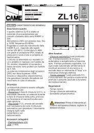
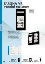
COLLEGAMENTO PER 2 MOTORI ABBINATI - CONNECTIONS FOR 2 COMBINED MOTORS<br />
CONNEXIONS POUR 2 MOTEURS ACCOUPLÉS<br />
ANSCHLUSSE FÜR 2 PARALLELGESCHALTETEN MOTOREN - CONEXIÓN PARA 2 MOTORES ACOPLADOS<br />
CAME<br />
CAME<br />
ITALIANO<br />
A<br />
- Coordinare il senso di marcia dei<br />
motoriduttori A e B, modificando la<br />
rotazione del motore B (vedi collegamento<br />
finecorsa);<br />
- Stabilire tra A e B il motore master (o<br />
pilota), posizionare il dip-switch 14 in<br />
ON sulla scheda comando. Per<br />
"master" s'intende il motore che comanda<br />
ambedue i cancelli, mentre<br />
sulla scheda comando del 2° motore<br />
posizionare il dip 11 in ON per renderlo<br />
inoperabile (slave) (1).<br />
- Assicurarsi che sia inserito il ricevitore<br />
radio solo sul quadro MASTER (2);<br />
- Eseguire solo sulla morsettiera<br />
MASTER i collegamenti elettrici e le<br />
selezioni predisposte normalmente (3);<br />
- Eseguire tra le morsettiere i collegamenti<br />
come da Fig. A;<br />
- Assicurarsi che tutti i dip del quadro<br />
del 2° motore siano disattivati (OFF)<br />
tranne il dip 11 (4).<br />
NOTA: se i due cancelli abbinati sono<br />
di dimensioni diverse, la funzione<br />
master deve essere inserita nel quadro<br />
del motore installato sull'anta più lunga.<br />
ON<br />
1<br />
"MASTER"<br />
1 2 3 4 5 6 7 8 9 10<br />
SCHEDA RADIOREQUENZA "A"<br />
"A" RADIO REQUENCY BOARD<br />
CARTE REQUENCE RADIO "A"<br />
RADIOREQUENZKARTE «A»<br />
TARJETA RADIORECUENCIA<br />
2<br />
AF<br />
4<br />
ON<br />
ON<br />
"SLAVE"<br />
1 2 3 4 5 6 7 8 9 10<br />
11 12 13 14 15 16 17 18 19 20<br />
B<br />
"SLAVE"<br />
SCHEDA BASE "MASTER"<br />
"MASTER" MOTHERBOARD<br />
CARTE DE BASE "MASTER"<br />
BASISKARTE "MASTER"<br />
TARJETA BASE «MASTER»<br />
R S T U V W E E1 EX E4 10 11 TS 1 2 3 3P 4 5 6 7 2MOT FC FA F 2 C1 CX B1 B2<br />
COLLEGAMENTI E SELEZIONI SUL QUADRO "MASTER"<br />
"MASTER" ELECTRICAL CONNECTIONS AND SELECTIONS<br />
CONEXION ET SÉLECTION SUR CARTE DE "MASTER"<br />
ELEKTRISCHEN ANSCHLÜSSE "MASTER"<br />
CONEXIONS Y SELECCIONES EN TARJETA BASE «MASTER»<br />
3<br />
CH1<br />
ON<br />
ON<br />
11 12 13 14 15 16 17 18 19 20<br />
CH2<br />
1 2 3 4 5 6 7 8 9 10<br />
CH1<br />
ON<br />
ON<br />
1 2 3 4 5 6 7 8 9 10<br />
CH2<br />
CH1<br />
11 12 13 14 15 16 17 18 19 20<br />
ON<br />
11 12 13 14 15 16 17 18 19 20<br />
CH2<br />
- 26 -
ENGLISH<br />
- Match the directions in which gear<br />
motors A and B rotate by changing the<br />
direction in which motor B rotates (see<br />
limit switch);<br />
- Set the master (or pilot) motor<br />
between A and B by setting dip-switch<br />
14 to ON on the control board.<br />
"Master" refers to the motor that<br />
controls both the gates. On the control<br />
board of the 2 nd motor, set dip-switch<br />
11 to ON to make it the "slave" (1).<br />
- Make sure that the radio receiver is<br />
activated only on the MASTER board<br />
(2);<br />
- Wire the electrical connections and<br />
the normally used selections only on<br />
the MASTER terminal board (3);<br />
- Wire the electrical connections<br />
between the terminal boards, as<br />
shown in the Fig. A;<br />
- Make sure that all the dip-switches<br />
on the board of the 2 nd motor are<br />
(OFF), except for dip 11 (4).<br />
NB: If the two coupled gates are of<br />
different sizes, the master function<br />
must be fitted to the motor control<br />
board installed on the longer door.<br />
RANÇAIS<br />
- Coordonnerle le sens de marche des<br />
motoreducteurs A et B en modifiantle<br />
sens de rotation du moteur B (voir fin<br />
de course);<br />
- Fixer entre A et B le moteur master<br />
(ou pilote) en positionnant le dip-switch<br />
14 sur ON sur la fiche commande. Par<br />
“master” il s’agit du moteur qui commande<br />
les deux grilles, tandis que sur<br />
la fiche de commande du 2sd moteur<br />
positionner le dip 11 sur ON pour qu’il<br />
soit piloté "slave" (1).<br />
- S'assurer que tous les récepteur radio<br />
est bien introduit seulement sur le<br />
pupitre MASTER (2);<br />
- Effecteur seulement sur la barrette de<br />
connexion MASTER les liaisons<br />
électriques et les sélections<br />
normalment prédisposées (3);<br />
- Effectuer les branchements entre les<br />
plaques à bornes de la façon indiquée<br />
sur la Fig. A;<br />
- S'assurer que tous les dip du pupitre<br />
du 2sd moteur sont éteints (OFF) à<br />
l'exception du dip 11 (4).<br />
NOTE: Si les deux grilles accouplées<br />
ont une dimension différente, la<br />
fonction maîtresse doit être prévue<br />
dans le tableau du moteur installé sur<br />
la porte la plus longue.<br />
IG. A<br />
ABB. A<br />
"MASTER"<br />
"SLAVE"<br />
E4 10 11 TS 1 2 3 3P 4 5 6 7 2MOT E4 10 11 TS 1 2 3 3P 4 5 6 7 2MOT<br />
Morsettiera motore master<br />
Master motor terminal block<br />
Plaque à bornes du moteur master<br />
Klemmbrett Mastermotor<br />
Cuadro de bornes motor master<br />
Morsettiera 2° motore<br />
Motor 2° terminal block<br />
Plaque à bornes du 2° moteur<br />
Klemmbrett 2° Motor<br />
Cuadro de bornes 2° motor<br />
- 27 -