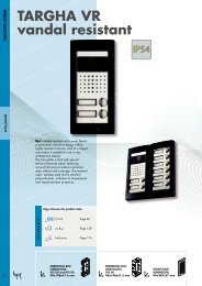

You also want an ePaper? Increase the reach of your titles
YUMPU automatically turns print PDFs into web optimized ePapers that Google loves.
CANCELLI AUTOMATICI<br />
SERIE TCA | TCA SERIES | SÉRIE TCA | BAUREIHE TCA | SERIE TCA | SERIE TCA<br />
CONTROLLO ACCESSI<br />
ACCESS CONTROL<br />
CONTRÔLE D’ACCESS<br />
ZUTRITT KONTROLL<br />
CONTROL DE ACCESOS<br />
TOEGANGSCONTROLE<br />
RBM 2<br />
Documentazione<br />
Tecnica<br />
S97<br />
rev. 0.5<br />
05/2002<br />
© CAME<br />
CANCELLI<br />
AUTOMATICI<br />
119RS97-GB<br />
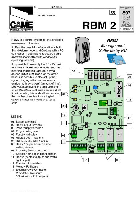
RBM2 is a control system for the simplified<br />
management of entries.<br />
It offers the possibility of operation in both<br />
Stand-Alone mode, and On-Line with a PC<br />
connection, installing the dedicated Came<br />
software (compatible with Windows 9x<br />
operating systems)<br />
It is possible to use only the RBM2's basic<br />
functions in Stand Alone mode, such as<br />
inserting or deleting Cards for normal<br />
access. In On-Line mode, on the other<br />
hand, it is possible to also set up the<br />
system for prepaid access (number of<br />
entries), with time credit (amount of time),<br />
anti-PassBack (Card one-time use) and<br />
timed PassBack (authorized entries at set<br />
time intervals); this mode allows counting 04<br />
the number of entries, indicating full<br />
capacity status by means of a traffic<br />
light.<br />
08<br />
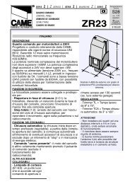
LEGEND<br />
01 Sensor terminals<br />
02 Relay output terminals<br />
03 Power supply terminals<br />
04 Programming keys<br />
05 Functions display<br />
06 RS 232 Door, max. 5 m<br />
07 RS 485 Door, max. 1000 m<br />
08 Relay 2 output actuation time<br />
setting trimmer<br />
09 Proximity Sensor on board<br />
10 Selection strip of on board sensor<br />
11 Relays (contact outputs and traffic<br />
light output)<br />
12 Function dip-switches<br />
13 Memory Roll board<br />
14 External Power Connector<br />
(12V AC-DC minimum<br />
600mA with ø 2.1mm jack)<br />
12<br />
10<br />
03<br />
14<br />
05<br />
TEMP<br />
+ -<br />
12-24<br />
AC-DC<br />
ENTER<br />
CH1<br />
CH2<br />
O 1 2<br />
N<br />
S1 S2 Gnd S3 S4 Gnd<br />
3 S4-IN<br />
2<br />
1 S4<br />
12-24<br />
AC-DC<br />
S4-IN<br />
RBM2<br />
RBM2<br />
Management<br />
Software by PC<br />
PROXIMITY CARD<br />
MEMORY ROLL<br />
CAME<br />
RS232<br />
RS485<br />
Gnd A B<br />
RL3 RL1 RL2<br />
Nc No C Nc No C No C<br />
PARKING OUT 1 OUT 2<br />
01 02<br />
09<br />
06<br />
13<br />
07<br />
11<br />
Copyright by Came Blu@Marketing
CONTENTS<br />
ENGLISH<br />
Technical Specifications § 1.0 - pg. 2<br />
Display messages § 1.1 - pg. 2<br />
Dip-Switch functions § 1.2 - pg. 2<br />
On-board sensor § 1.3 - pg. 2<br />
Connections § 1.4 - pg. 3<br />
Saving the 1 st Card (Master Card) § 2.0 - pg. 4<br />
Saving of Cards § 2.1 - pg. 4<br />
Change relay channel § 2.2 - pg. 4<br />
Creation of 2 nd Master Card § 2.3 - pg. 5<br />
Deletion of Cards § 2.4 - pg. 5<br />
Data saving § 2.5 - pg. 6<br />
Data restoration § 2.6 - pg. 6<br />
Total deletion of Cards § 2.7 - pg. 7<br />
Software Installation § 3.0 - pg. 8<br />
1.0<br />
Technical Specifications<br />
1.1<br />
Display messages<br />
- Power supply: 12-24V ac/dc<br />
- Absorption: 24V = 650 mA<br />
12V = 1 A<br />
- Relay outputs: 2<br />
- Traffic light output: 1 (only in On-line<br />
mode)<br />
- RS 232 port for PC connection (5 m<br />
max distance)<br />
- RS 485 port for PC connection (max.<br />
1000 m distance, with PC40 interface)<br />
- Extractable-connection terminal boards<br />
- Number of Cards that can be saved: 500<br />
proximity Cards and/or strip (magnetic)<br />
Cards<br />
- Setup: with the Master Card in<br />
Stand-Alone mode; with software in<br />
On-Line mode.<br />
When powering the<br />
RBM2, if the<br />
memory is<br />
completely empty,<br />
all the central segments of the display<br />
will come on.<br />
If there are<br />
memory<br />
allocations already<br />
assigned, a<br />
hyphen will appear on the left display<br />
screen.<br />
It also indicates the Stand-By position.<br />
1.2<br />
Dip-Switch functions<br />
1.3<br />
On-Board sensor<br />
DIP 1 ON<br />
relay 1 stepper function<br />
DIP 1 OFF<br />
relay 1 bistable function<br />
O 1 2<br />
N<br />
O 1 2<br />
N<br />
It is a proximity sensor incorporated in<br />
the board.<br />
It emulates reader 4 and it saves Cards<br />
(only proximity cards) directly on the<br />
board in case the readers are far away.<br />
Activate it (and disactivate it when saving<br />
is over) with the selection strip, see pg. 3.<br />
- 2 -<br />
DIP 2<br />
No Function
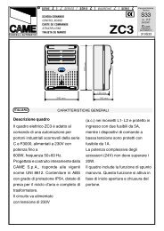
1.4<br />
Connections<br />
ON-BOARD SENSOR<br />
SELECTION<br />
Adjustment<br />
Timing<br />
Relay 2 (RL2)<br />
from 1 to 5 min.<br />
ENTER<br />
CH1<br />
CH2<br />
TEMP<br />
O 1 2<br />
N<br />
S4-IN<br />
PROXIMITY CARD<br />
MEMORY ROLL<br />
CAME<br />
RS232<br />
RS485<br />
Gnd A B<br />
Jumpers<br />
1 and 2<br />
enable<br />
reader 4<br />
(default)<br />
3 S4-IN<br />
2<br />
1 S4<br />
Jumpers<br />
3 S4-IN<br />
2 and 3 2<br />
enable 1 S4<br />
On-Board sensor<br />
ENGLISH<br />
3 S4-IN<br />
2<br />
1 S4<br />
Power supply<br />
12 - 24V<br />
ac/dc<br />
+ -<br />
12-24<br />
AC-DC<br />
S1 S2 Gnd S3 S4 Gnd<br />
12-24<br />
AC-DC<br />
RBM2<br />
RL3 RL1 RL2<br />
Nc No C Nc No C No C<br />
PARKING OUT 1 OUT 2<br />
Reader 1<br />
ENTRY<br />
MAGNEET<br />
KAART<br />
PROXIMITY<br />
CARD<br />
Red<br />
Black<br />
Output Contact Relay 2<br />
(RL2) max. 10A - 230V<br />
Output Contact Relay 1<br />
(RL1) max. 10A - 230V<br />
Reader 2<br />
ENTRY<br />
Red<br />
Output Contact Relay 3 (RL3)<br />
TRAFFIC LIGHT<br />
max. 5A - 230V<br />
Reader 3<br />
EXIT<br />
Red<br />
Red<br />
Black<br />
P<br />
CLEAR<br />
FULL<br />
Reader 4<br />
EXIT<br />
Can only be activated in<br />
On-Line mode<br />
THE FOLLOWING PAGES ILLUSTRATE ALL THE OPERATIONS THAT CAN BE CARRIED OUT IN STAND-ALONE<br />
MODE WITH PROXIMITY SENSORS; THE SAME INSTRUCTIONS CAN BE FOLLOWED FOR STRIP READERS<br />
WITH THE WARNING THAT, WHERE IT IS INSTRUCTED TO "FEED", "POSITION", "SWIPE" OR "SLIDE", IT<br />
IS NECESSARY TO SWIPE OR SLIDE THE CARD ACROSS THE READER.<br />
FOR INSTRUCTIONS IN ON-LINE MODE, PLEASE CONSULT THE CAME SOFTWARE.<br />
- 3 -
9<br />
10<br />
8<br />
11<br />
7<br />
12<br />
6<br />
9<br />
9<br />
10<br />
8<br />
10<br />
8<br />
1<br />
5<br />
11<br />
7<br />
11<br />
7<br />
2<br />
4<br />
3<br />
12<br />
6<br />
12<br />
6<br />
1<br />
5<br />
1<br />
5<br />
2<br />
4<br />
2<br />
4<br />
3<br />
3<br />
9<br />
10<br />
8<br />
9<br />
10<br />
8<br />
11<br />
7<br />
11<br />
7<br />
12<br />
6<br />
12<br />
6<br />
1<br />
5<br />
2<br />
4<br />
1<br />
5<br />
3<br />
2<br />
4<br />
3<br />
2.0<br />
Saving the 1st Card (Master Card)<br />
Press the ENTER key, F - 1 appears on the display<br />
(if no operation takes place for 10", the message disappears<br />
and RBM2 is set to STAND BY)<br />
ENTER<br />
ENTER<br />
10"<br />
ENGLISH<br />
Press Enter again... F - 1 1 flashes<br />
Place the Card on the sensor (for 2”); when saving is<br />
complete, on the display the first central segment on the left<br />
lights up while on the sensor both LEDs flash (the first card<br />
saved is called MASTER and the display screen shows<br />
flashing areas).<br />
MASTER<br />
2"<br />
2.1<br />
Saving of Cards<br />
Feed the Master card in sequence twice (within max 3");<br />
RBM2 enters the insertion stage.<br />
The Display flashes, indicating the memory location in red<br />
numbers, while the green number indicates the output relay.<br />
(change channel, see § 2.2)<br />
MASTER<br />
CARD 01<br />
2 X<br />
2"<br />
Feed the card that needs to be stored and keep it on the<br />
sensor until the display shows the message “Sto”. When the<br />
message disappears, RBM2 moves to the subsequent<br />
position of free memory.<br />
CARD 02<br />
The display flashes, while on the sensor both LEDs<br />
flash. In this phase sequential storage of cards is<br />
possible.<br />
After the saving of the last card, wait 10” and RBM2 is<br />
moves again to Stand By.<br />
10"<br />
2.2<br />
Change relay channel<br />
During the insertion of the card, it is possible to alter the<br />
activation of the output relay from RL1 to RL2 and vice<br />
versa.<br />
The operation takes place during the Card saving stage<br />
(see § 2.1) when the Master Card is slid in order to begin the<br />
procedure. It can simply be slid again and the display on the<br />
right (green) changes from 1 to 2; then, show the card to be<br />
saved and wait until the display shows the "Sto" message.<br />
By default, all the cards activate relay 1.<br />
MASTER<br />
MASTER<br />
CARD 01<br />
2"<br />
- 4 -
2.3<br />
Creation of 2nd Master Card<br />
By using a card that has already been saved, a second Master Card can be created.<br />
(N.B. RBM2 accepts only two Master Cards)<br />
Operation<br />
Display<br />
Sequence<br />
Swipe the Master Card<br />
MASTER<br />
Press ENTER Display F - 1<br />
ENTER<br />
Press CH1 Display F - 2<br />
Press ENTER<br />
F - 2 flashes<br />
CH 1<br />
ENTER<br />
ENGLISH<br />
Swipe the Card that will be<br />
saved as the 2nd Master<br />
Once saving is over, the<br />
display screen displays<br />
F - 2 M steadily<br />
CARD 01<br />
2.4<br />
Deletion of Cards<br />
Sequence of operations to carry out in order to delete one or more Cards.<br />
Operation<br />
Display<br />
Sequence<br />
Swipe the Master Card<br />
MASTER<br />
Press ENTER Display F - 1<br />
ENTER<br />
Press CH1 3 times<br />
Display F - 4<br />
3x<br />
CH 1<br />
Press ENTER<br />
The first memory location<br />
appears<br />
ENTER<br />
Press CH1 - CH2<br />
Choose the location to<br />
eliminate<br />
CH 1<br />
CH 2<br />
Press ENTER<br />
The location is eliminated<br />
and C starts flashing<br />
When the C flashes, it means that the location is free. When it is steady, it means the memory<br />
location is occupied. Once the Card deletion operation is over, the display flashes for 10 seconds<br />
before it returns to STAND-BY (see page 2 § 1.3).<br />
- 5 -
9<br />
10<br />
8<br />
9<br />
10<br />
8<br />
11<br />
7<br />
11<br />
7<br />
12<br />
6<br />
12<br />
6<br />
1<br />
5<br />
1<br />
2<br />
5<br />
4<br />
3<br />
2<br />
4<br />
3<br />
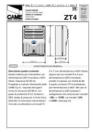
2.5<br />
Data Saving<br />
Download Function<br />
This function allows the data included in the RBM2 to be saved<br />
by transferring it into the "MEMORY ROLL" board.<br />
To carry out this operation, insert the board MEMORY into the<br />
corresponding connector (see Fig.1).<br />
MEMORY ROLL<br />
MEMORY ROLL<br />
CAME<br />
Fig.1<br />
ENGLISH<br />
Carry out the insertion making sure the power<br />
supply is turned off.<br />
Operation Display Sequence<br />
Swipe the Master Card<br />
MASTER<br />
Press ENTER Display F - 1<br />
CH 1<br />
Press CH1 6 times Display F - 7<br />
6X<br />
ENTER<br />
Press ENTER<br />
Display F - 7 U<br />
At the end of the operation,<br />
the display screen displays<br />
the hyphen on the left.<br />
ENTER<br />
2"<br />
2.6<br />
Data restoration<br />
UPLOAD Function<br />
This function allows the data that has been saved in the MEMORY roll board to be<br />
restored in the RBM2.<br />
To carry out this operation, insert the board MEMORY into the corresponding<br />
connector (see Fig.1).<br />
Carry out the insertion making sure the power<br />
supply is turned off.<br />
Operation Display Sequence<br />
Swipe the Master Card<br />
MASTER<br />
Press ENTER Display F - 1<br />
Press CH1 7 times Display F - 8<br />
7x<br />
CH 1<br />
ENTER<br />
Press ENTER<br />
Display F - 8 d<br />
ENTER<br />
- 6 -<br />
At the end of the operation,<br />
the display screen displays<br />
the hyphen on the left.<br />
2"
2.7<br />
Total deletion of Cards<br />
Steps to be carried out to delete in a single operation all the cards that have been saved.<br />
Operation<br />
Display<br />
Sequence<br />
Swipe the Master Card<br />
MASTER<br />
Press ENTER Display F - 1<br />
ENTER<br />
Press CH1 4 times Display F - 5<br />
Press ENTER<br />
The C L r A message<br />
flashes on<br />
4X<br />
CH 1<br />
ENTER<br />
ENGLISH<br />
Keep the ENTER key pressed<br />
The C L r A message<br />
stops flashing.<br />
Once the deletion has been performed, the display flashes with the C L r A message for 10<br />
seconds before it returns to STAND-BY (see page. 2 § 1.3).<br />
- 7 -
3.0<br />
Software Installation<br />
Insert the first diskette in the drive and proceed as<br />
follows for software installation:<br />
Fig.1 From the Windows toolbar click on the START,<br />
select RUN, and type: A:\SETUP and confirm by<br />
clicking OK.<br />
Fig.2 A window will appear that will update some files<br />
of the system (the duration of the operation depends on<br />
your PC),<br />
Fig.3 You will be prompted to insert the second<br />
diskette in the drive. Insert it and confirm by clicking<br />
OK.<br />
Fig.4 Once file saving is over, the Software Installation<br />
window will appear; press OK to proceed.<br />
Fig.5 By carrying on to the next window you can<br />
choose where to instal the program by clicking on<br />
"Change Directory ", or click on the icon for the default<br />
installation (c:\programs\came\rbm2).<br />
Fig.6 You will be asked to confirm the position of the<br />
connections on the toolbar, press "Continue" (if you do not<br />
want to change the position).<br />
Once the files have been copied, a window appears<br />
that confirms that the installation has been made. Click<br />
OK and reboot the computer to apply the new settings.<br />
CANCELLI AUTOMATICI<br />
ASSISTENZA TECNICA<br />
NUMERO VERDE<br />
800 295830<br />
WEB<br />
www.came.it<br />
E-MAIL<br />
info@came.it<br />
SISTEMA QUALITÀ<br />
CERTIFICATO<br />
CAME CANCELLI AUTOMATICI S.P.A.<br />
DOSSON DI CASIER (TREVISO)<br />
(+39) 0422 4940 (+39) 0422 4941<br />
CAME LOMBARDIA S.R.L.___COLOGNO M. (MI)<br />
(+39) 02 26708293 (+39) 02 25490288<br />
CAME SUD S.R.L. _________________NAPOLI<br />
(+39) 081 7524455 (+39) 081 7529109<br />
CAME (AMERICA) L.L.C._________MIAMI (FL)<br />
(+1) 305 593 8798 (+1) 305 593 9823<br />
CAME AUTOMATISMOS S.A_________MADRID<br />
(+34) 091 5285009 (+34) 091 4685442<br />
CAME BELGIUM NV-SA___________LESSINES<br />
(+32) 068 333014 (+32) 068 338019<br />
CAME FRANCE S.A.___NANTERRE CEDEX (PARIS)<br />
(+33) 01 46130505 (+33) 01 46130500<br />
CAME GMBH____KORNTAL BEI (STUTTGART) (+49)<br />
07 11839590 (+49) 07 118395925<br />
CAME GMBH________SEEFELD BEI (BERLIN) (+49)<br />
03 33988390 (+49) 03 339885508<br />
CAME PL SP.ZO.O_________WARSZAWA (+48)<br />
022 8365076 (+48) 022 8369920<br />
CAME UNITED KINGDOM LTD___NOTTINGHAM<br />
(+44) 01159 210430 (+44) 01159 210431