JBL - K2 S9800 - White Paper (english) (2001).
JBL - K2 S9800 - White Paper (english) (2001).
JBL - K2 S9800 - White Paper (english) (2001).

Create successful ePaper yourself
Turn your PDF publications into a flip-book with our unique Google optimized e-Paper software.
<strong>JBL</strong> <strong>White</strong> <strong>Paper</strong><br />
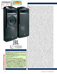
The New <strong>K2</strong>.<strong>S9800</strong> Loudspeaker System<br />
By <strong>JBL</strong> Technical Staff<br />
TIMOTHY PRENTA<br />
Director, <strong>JBL</strong> Consumer Engineering<br />
<strong>JBL</strong> Consumer Products<br />
GREG TIMBERS<br />
Chief System Engineer<br />
<strong>JBL</strong> Consumer Products<br />
JERRY MORO<br />
Senior Transducer engineer<br />
<strong>JBL</strong> Consumer<br />
DOUGLAS BUTTON<br />
Vice President, Research & Development<br />
<strong>JBL</strong> Professional<br />
Editor<br />
John M. Eargle<br />
Advisor<br />
<strong>JBL</strong> Consumer & Professional
FIFTH DRAFT (15 May <strong>2001</strong>)<br />
<strong>JBL</strong> <strong>White</strong> <strong>Paper</strong>: The New <strong>K2</strong>.<strong>S9800</strong> Loudspeaker System<br />
A. Introduction The Design Brief:<br />
By <strong>JBL</strong> Technical Staff<br />
The advent of high-density recorded media for the consumer has challenged manufacturers of<br />
loudspeakers and microphones to push the frequency response envelope of transducers and<br />
systems up to 50 kHz in order take advantage of the program signals that can now be recorded in<br />
the DVD-Audio and Sony-Philips SACD software formats. The issue is not so much whether<br />
listeners can hear this uppermost octave as such, but rather that the bandwidth extension ensures<br />
smoother and less aberrated frequency response in the upper portion of the normal audio<br />
bandwidth than we have known before.<br />
Another major consideration is uniformity of acoustical power radiation from the loudspeaker<br />
into the listening space. There are two aspects here: smooth on-axis response and controlled<br />
vertical and lateral radiation angles. Studies carried out by various technical groups within the<br />
Harman organization have shown a universal preference on the part of professionals and critical<br />
consumers for loudspeakers that exhibit such response uniformity.<br />
At the same time, there is an ever stronger demand from critical listeners for lower distortion in<br />
loudspeaker systems, effectively matching the low distortion normally found in the best<br />
microphones, recording systems and playback electronics.<br />
In addition to the foregoing requirements, critical listeners demand realistic playback levels with<br />
minimal compression of dynamics. While there may be several approaches to achieving<br />
bandwidth extension and uniform power response, there remains only one way to ensure high<br />
playback levels with high dynamic linearity — and that is through the use of over-designed<br />
transducers that are capable of output levels many times greater than will normally be required of<br />
them.<br />
In critical loudspeaker auditioning sessions, listeners become very aware of subtle timbral<br />
aspects which are often difficult to measure. Such matters as cone materials, high frequency<br />
diaphragm materials and dividing network component integrity become important design<br />
considerations in defining a modern state of the art loudspeaker system.<br />
Finally, the appearance and shape of a fine loudspeaker system must reflect natural and pleasing<br />
proportions, show use of the finest materials, and be acoustically correct insofar as physical<br />
boundary conditions for transducer performance is concerned.<br />
In this <strong>White</strong> <strong>Paper</strong> we will examine transducer, horn and system designs in detail, discussing all<br />
aspects of their engineering and development. We will then move on to the evolution of the<br />
1
system concept and the integration of the elements into the whole. We will conclude with a<br />
discussion of system setup and optimization in typical listening spaces.<br />
B. The Transducers:<br />
Low-Frequency Driver:<br />
The Model 1500AL LF driver was designed by Jerry Moro, Senior Development Engineer for<br />
<strong>JBL</strong> Consumer Products. It is a 380 mm diameter device with a 100 mm voice coil completely<br />
immersed in a radial field generated by an Alnico 5DG magnet. A section view of the driver is<br />
shown in Figure 1. Its salient features are:<br />
1. Large outer suspension, made of EPDM foam rubber material, which offers low mass, low<br />
losses and much improved longevity.<br />
2. Double Nomex inner suspensions, inverted with respect to each other for cancellation of evenorder<br />
distortion components. All suspension elements are tailored for maximum mechanical<br />
displacement linearity.<br />
3. A very large aluminum shorting ring positioned below the gap to reduce global flux<br />
modulation of the static field. This eliminates the demagnetization problems that have plagued<br />
Alnico motor designs in the past.<br />
4. Use of alternating copper-steel laminations in the top plate. The presence of the copper rings<br />
provides the familiar <strong>JBL</strong> shorting ring adjacent to the voice coil to reduce its inductance and to<br />
further stabilize the local magnetic field throughout the steel in the long gap length. The presence<br />
of the steel laminations produces an effectively narrow magnetic gap through the "sharing" of<br />
space with the copper.<br />
5. The use of Alnico 5DG magnet material provides a stable magnetic operating point under high<br />
drive conditions, further reducing distortion due to flux modulation. The magnetic circuit has<br />
been optimized for flux consistency throughout the normal range of voice coil movement, and<br />
the moving system has a linear operating range of ±12.7 millimeters.<br />
6. Choice of cone material. A traditional felted material of thick cross-section was chosen for its<br />
combination of high internal damping, mass, mechanical stiffness and freedom from acoustical<br />
coloration.<br />
7. A fully vented frame and motor structure is used for minimizing acoustic losses and for<br />
cooling of internal parts through optimum transfer of air into and out of the magnetic structure.<br />
Altogether, these factors provide: lower losses at high frequencies, reduced harmonic distortion,<br />
and improved power handling.<br />
Pertinent mechanical, magnetic and acoustical parameters of the 1500 Al LF driver are:<br />
2
Flux density: 0.52 tesla throughout the 40.64 mm long gap<br />
Bl product: 21 T»m<br />
Voice coil resistance: 5.3 ohms<br />
Voice coil winding length: 20.32 mm<br />
Free-air resonance frequency: 26 Hz<br />
Peak-to-peak: linear excursion capability: 25.4 mm<br />
Weight of magnetic structure: 13.6 kg (without cover)<br />
Driver sensitivity (1 watt at one meter): 94 dB SPL<br />
[Insert Figure 1 about here.]<br />
Mid-Frequency Compression Driver and Horn:<br />
The model 435 Be compression midrange driver was designed by Douglas Button, Vice<br />
President of Engineering for <strong>JBL</strong> Professional. It makes use of a 75 mm diameter diaphragm<br />
operating into a traditional Western Electric type annular slit phasing plug. The use of<br />
neodymium magnetic material keeps the size of the driver to a minimum. Figure 2 shows a<br />
section view of the midrange compression driver.<br />
Its salient features are:<br />
1. As an intermediate size between <strong>JBL</strong>'s large and small format compression drivers,<br />
derivatives of the 435 have found great use in <strong>JBL</strong>'s recent professional line arrays, where the<br />
small size of the driver and its magnetic structure allow them to be used in multiples for driving<br />
high frequency line arrays without the design and fit problems that would be unavoidable with<br />
large format drivers.<br />
2. The phasing plug and initial flare development are both of the newer rapid flare type, which<br />
reduces second harmonic distortion by up to 6 dB, relative to <strong>JBL</strong>'s earlier driver technology.<br />
3. With efficiency in the range of 25 - 30%, the driver can deliver high amounts of acoustical<br />
power with relatively little electrical input. The diaphragm is made of beryllium, whose pistonic<br />
behavior is maintained to well beyond 15 kHz. The diaphragm is coated with a fine layer of<br />
Aquaplas for damping of spurious resonances.<br />
[Insert Figure 4 about here.]<br />
4. Pertinent magnetic and acoustical details:<br />
Mass of moving system: 1.25 g<br />
Flux density in gap: 20 tesla (20 kGs)<br />
. Magnetic assembly weight: 1 kg<br />
Figure 5 shows a plane wave tube response curve of the 435 Be driver.<br />
3
[Insert Figure 2 about here.]<br />
The 435 Be driver is attached to a Bi-Radial horn designed by Greg Timbers, Chief Engineer<br />
of <strong>JBL</strong> Consumer. It is executed in a high impact plastic that has high dimensional stability.<br />
Horn section views are shown in Figure 3. The -6 dB beamwidth plots and directivity data are<br />
shown in Figure 4. Note that the pattern control is uniform (±10°) from 1 kHz to 10 kHz. The DI<br />
is within ±1 dB over the same frequency range.<br />
[Insert Figures 3 and 4 about here.]<br />
Ultra-High-Frequency (UHF) Compression Driver and Horn:<br />
The 045 Be UHF compression driver was designed by Tim Prenta, Director of Engineering for<br />
<strong>JBL</strong> Consumer products. With its 25-mm beryllium diaphragm and 50-mm neodymium magnetic<br />
structure, this is the smallest compression driver that <strong>JBL</strong> has ever designed. The pure beryllium<br />
diaphragm is less than 0.04 mm thick and has a mass of only 0.1 gram. The single layer<br />
aluminum ribbon voice coil is wound without a former and attached directly to the diaphragm.<br />
The driver employs the smallest annular slit phasing plug that <strong>JBL</strong> has ever designed. Each<br />
phasing plug assembly is manufactured by modern stereo lithography techniques for absolute<br />
dimensional integrity. A section view of the 045 BE driver is shown in Figure 5.<br />
The extremely low mass of the moving system, high magnetic flux density and the high rigidity<br />
of beryllium produce response that is essentially flat from 10 kHz to 48 kHz, as seen in Figure 6.<br />
[Insert Figures 5 and 6 about here.]<br />
The UHF horn was designed by Greg Timbers. It is properly scaled to maintain a coverage angle<br />
of 60 degrees in the horizontal plane and 30 degrees in the vertical plane over the frequency<br />
interval from 10 kHz to 50 kHz.<br />
Pertinent magnetic and acoustical details:<br />
Mass of moving system: 0.3 g<br />
Flux density in gap: 20 tesla (20 kGs)<br />
Magnetic assembly weight: 0.21 kg<br />
Figure 7 shows various views of the UHF horn. Figure 8 shows pattern control and directivity<br />
for the horn.<br />
[Insert Figures 7 and 8 about here.]<br />
C. System design and component integration:<br />
4
Figure 9 shows front, top, side and perspective line drawings of the systems, illustrating the<br />
various curved transitions that define the smooth acoustical boundary conditions for the LF<br />
driver and the MF and UHF horns.<br />
The dividing network topology combined with the acoustic behavior of the individual<br />
transducers provides 24-dB-per-octave transitions between adjacent system elements. The<br />
response of each element is -6 dB at the transition frequency. These rapid transitions provide<br />
more uniform system response over a larger vertical listening angle than that provided by lowerorder<br />
slopes, and this translates into an increased solid listening angle for the system. The<br />
contribution of each element, along with the overall on-axis response of the system is shown in<br />
Figure 10.<br />
Another important factor in the design of the dividing network is the use of DC biasing of the<br />
capacitors in this system. The biasing ensures that normal zero-crossings of the audio waveform<br />
from plus to minus are displaced from actual zero potential and thus do not force the capacitors<br />
to undergo a zero charge condition, even momentarily. This is analogous to "Class A" behavior<br />
in amplifiers.<br />
[Insert Figures 9 and 10 about here.]<br />
Details of the system's directional response are shown in Figure 11. This family of curves is<br />
defined as follows:<br />
Curve 1. On-axis response.<br />
Curve 2. Average of response over 30° horizontal and 15° vertical angles.<br />
Curve 3. First reflected sound power sum.<br />
Curve 4. Total reflected sound power sum.<br />
Curve 5. On-axis overall directivity index (dB).<br />
Curve 6. On-axis directivity index for first reflections (dB).<br />
[Insert Figure 11 about here.]<br />
The overall trend is for the system to be fairly nondirectional at low frequencies, reaching a<br />
plateau of uniformity at about 1 kHz, where the midrange Bi-Radial horn comes into play, and<br />
extending beyond 20 kHz as the UHF takes over.<br />
Under these conditions the system will integrate well with a wide variety of acoustical<br />
conditions. In a room where the boundary absorption is uniform over the midrange, the system<br />
will provide ideal spectral coverage over a broad listening angle.<br />
The impulse response of the system is shown in Figure 12. The response shows system time<br />
alignment within an interval of about 350 microseconds, along with highly damped low<br />
frequency response<br />
[Insert Figure 12 about here.]<br />
5
From an electronic point of view, we want to ensure that the system does not present a<br />
troublesome electrical load to any amplifier that is chosen to drive the system. Figure 13 shows<br />
the modulus of impedance as not dropping below 6 ohms at any point over the range below 10<br />
kHz. The drop to about 3 ohms at 50 kHz is considered negligible.<br />
[Insert Figure 13 about here.]<br />
Overall system distortion at reference level of 102 dB at a measuring distance of one meter is<br />
shown in Figure 14. Because the fundamental response is so uniform we can add at the right edge<br />
of the graph an approximate scale indicating distortion percentage from the range of about 60 Hz<br />
to 20 kHz. The second and third harmonic distortion components at this extremely high playback<br />
level are amazingly low. Only in the range above about 5 kHz does the value of second harmonic<br />
(dashed curve) rise slightly above one percent.<br />
[Insert Figure 14 about here]<br />
D. System Integration into the Listening Room:<br />
The target consumer for the <strong>K2</strong>.<strong>S9800</strong> system will probably already know enough about<br />
loudspeaker positioning in the home listening environment to ensure good results with a pair of<br />
these new loudspeakers in normal stereo configuration. It is for the listener who wants to use<br />
these loudspeakers in a surround sound configuration that we offer the following<br />
recommendations.<br />
The ITU (International Telecommunications Union) standard for surround loudspeaker<br />
placement is shown in Figure 15. When possible, the circular outline of loudspeaker location<br />
should be maintained. If it is necessary to place the three frontal loudspeakers against a wall, then<br />
the center loudspeaker should be time-delayed so that its effective distance from the primary<br />
listening position will be equal to that of the left and right front channels. In calibrating the<br />
system levels at the primary listening position, any differences in distance to the primary<br />
listening position should be taken into account so that both level and relative timing from all five<br />
channels will be the same at the center listening position.<br />
Since the ITU recommendation is basically a broad guideline, individual users may modify it in<br />
minor ways to fit the requirements of a given listening space. Specifically, the placement of rear<br />
channels may be changed slightly to allow for difficulties in room setup. Some listeners may<br />
prefer the rear channels to be slightly greater than the ±110° limit shown here. In any event, both<br />
rear channels should be at the same off-axis angle, relative to the center channel, to maintain<br />
system left-right balance.<br />
Figure captions:<br />
1. Section view of 1500AL low frequency transducer.<br />
2. Section view of 435 Be mid-frequency compression driver.<br />
6
3. Vertical and horizontal profiles of the mid-frequency Bi-Radial horn.<br />
4. -6-dB beamwidth and directivity data for the mid-frequency horn over its nominal operating<br />
range.<br />
5. Section view of the 045 Be UHF compression driver.<br />
6. Unequalized on-axis response of the UHF system.<br />
7. Vertical and horizontal profiles and views of the UHF horn.<br />
8. -6-dB beamwidth and directivity data form the UHF horn over its nominal operting range.<br />
9. Front, side, top and perspective line drawings of the complete system.<br />
10. On-axis contributions of LF, MF and UHF sections of the system.<br />
11. Overall system directional and room response.<br />
12. System impulse response.<br />
13. System modulus of impedance.<br />
14. Second and third harmonic distortion at 102 dB SPL at a measuring distance of one meter.<br />
15. Target loudspeaker locations for surround sound playback.<br />
7