Airfoil Development for the Trek Speed Concept ... - Slowtwitch.com
Airfoil Development for the Trek Speed Concept ... - Slowtwitch.com
Airfoil Development for the Trek Speed Concept ... - Slowtwitch.com

You also want an ePaper? Increase the reach of your titles
YUMPU automatically turns print PDFs into web optimized ePapers that Google loves.
1.2 Implementation of Turbulence-Inducing Features (i.e. Dimples)<br />
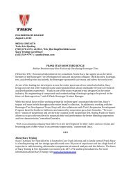
Logically, in order to delay flow separation, <strong>the</strong> boundary layer must be turned turbulent upstream from <strong>the</strong> laminar boundary layer<br />
separation point, as shown in <strong>the</strong> figure below. So, any turbulence-inducing feature located downstream from <strong>the</strong> separation point<br />
per<strong>for</strong>ms no practical function, and only has <strong>the</strong> potential to create unnecessary skin friction drag or turbulence. A golf ball is only<br />
dimpled across its entire surface to account <strong>for</strong> every possible ball orientation. Since <strong>the</strong> relative-wind orientation of bicycle tubes and<br />
<strong>com</strong>ponents (even those rotating) is fairly limited, <strong>the</strong> functionality of turbulence-inducing features is limited to a single specific area.<br />
As previously mentioned, <strong>the</strong> lowest possible drag is achieved when flow separation is avoided without <strong>the</strong> aid of any turbulenceinducing<br />
features.<br />
Figure 25: Flow around a smooth sphere (top) and around <strong>the</strong><br />
same sphere with a turbulence-inducing feature upstream<br />
from <strong>the</strong> laminar boundary layer separation point [16]. This<br />
is why golf balls are dimpled [15].<br />
2 The KVF’s Negative Drag (Thrust!)<br />
Because flying devices are not restricted to travel in a predetermined direction, airfoil aerodynamic <strong>for</strong>ces are traditionally measured<br />
in <strong>the</strong> axes parallel (drag) and perpendicular (lift) to <strong>the</strong> wind. In contrast, bicycles are on wheels which limit <strong>the</strong>ir motion to a single<br />
direction. While this distinction is seemingly trivial, it results in a whole different set of aerodynamic rules.<br />
In cycling <strong>the</strong> aerodynamic <strong>for</strong>ces are measured in <strong>the</strong> bike-axes, not <strong>the</strong> wind-axes. The reason is simple: it is <strong>the</strong> aerodynamic <strong>for</strong>ce<br />
<strong>com</strong>ponent in <strong>the</strong> direction of bicycle motion (drag) which consumes energy. The rest of <strong>the</strong> aerodynamic <strong>for</strong>ce – <strong>the</strong> <strong>com</strong>ponent in<br />
<strong>the</strong> direction perpendicular to bicycle motion – consumes no energy because <strong>the</strong> wheels restrict all motion in this direction. Stated<br />
ma<strong>the</strong>matically, <strong>the</strong> distance traveled in this direction is zero, and work (energy) is <strong>the</strong> product of <strong>for</strong>ce and distance.<br />
21