Airfoil Development for the Trek Speed Concept ... - Slowtwitch.com
Airfoil Development for the Trek Speed Concept ... - Slowtwitch.com
Airfoil Development for the Trek Speed Concept ... - Slowtwitch.com

Create successful ePaper yourself
Turn your PDF publications into a flip-book with our unique Google optimized e-Paper software.
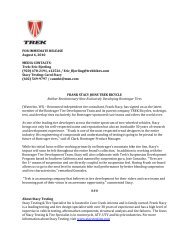
The results of this experiment were dramatic. Filmed at 7,500 frames per second, <strong>the</strong> airflow around four fundamental tube shapes at<br />
10˚ yaw was revealed in full detail. A still image from each of <strong>the</strong>se four videos is shown side-by-side in <strong>the</strong> figure below.<br />
Figure 18: Snapshot of <strong>the</strong> airflow around<br />
several airfoil shapes with <strong>the</strong> flow paths<br />
identified. Notes: 30 mph airflow in <strong>the</strong><br />
vertical direction. <strong>Airfoil</strong>s yawed 10˚ to <strong>the</strong><br />
right. Taken from a video filmed at 7,500<br />
frame per second. San Diego Low <strong>Speed</strong><br />
Wind Tunnel.<br />
In <strong>the</strong> previous figure, <strong>the</strong> wind direction is vertical from top to bottom, and each airfoil is yawed to 10˚ to <strong>the</strong> right, and <strong>the</strong> airspeed<br />
is 30 mph. The cross-sections were scaled such that each had <strong>the</strong> same lateral moment of inertia (lateral stiffness). The dashed lines<br />
indicate <strong>the</strong> air path across <strong>the</strong> trailing sidewall of <strong>the</strong> airfoil (<strong>the</strong> side on which flow separation occurs).<br />
As can be seen, <strong>the</strong> round cross-section (shape 1) has extremely early flow separation. In <strong>the</strong> video, <strong>the</strong> classic Kármán Vortex Street<br />
[10] of alternating eddies is clearly seen. The large turbulent wake results in extremely high drag.<br />
The traditional bicycle airfoil (shape 2) is a significant improvement over <strong>the</strong> cylinder. However, it still generates a significant wake<br />
because <strong>the</strong> flow separates from <strong>the</strong> trailing (right) wall. One indicator of this lack of flow attachment is that <strong>the</strong> wake does not turn<br />
in <strong>the</strong> direction of <strong>the</strong> airfoil. Instead, <strong>the</strong> air hits airfoil and spreads out, continuing in its original vertical direction.<br />
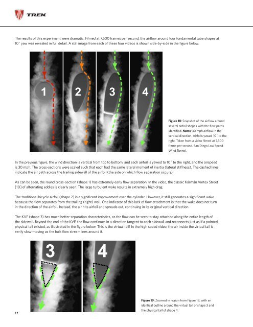
The KVF (shape 3) has much better separation characteristics, as <strong>the</strong> flow can be seen to stay attached along <strong>the</strong> entire length of<br />
<strong>the</strong> sidewall. Beyond <strong>the</strong> end of <strong>the</strong> KVF, <strong>the</strong> flow continues in a direction tangent to each sidewall and reconnects just as if a pointed<br />
physical tail existed, as illustrated in <strong>the</strong> figure below. This is <strong>the</strong> virtual tail! In <strong>the</strong> high speed video, <strong>the</strong> air inside <strong>the</strong> virtual tail is<br />
eerily slow-moving as <strong>the</strong> bulk flow streamlines around it.<br />
17<br />
Figure 19: Zoomed in region from Figure 18, with an<br />
identical outline around <strong>the</strong> virtual tail of shape 3 and<br />
<strong>the</strong> physical tail of shape 4.