Airfoil Development for the Trek Speed Concept ... - Slowtwitch.com
Airfoil Development for the Trek Speed Concept ... - Slowtwitch.com
Airfoil Development for the Trek Speed Concept ... - Slowtwitch.com

Create successful ePaper yourself
Turn your PDF publications into a flip-book with our unique Google optimized e-Paper software.
3 KVF Theory<br />
It is widely known that, within limits, high aspect ratio airfoils have lower drag than low aspect ratio airfoils [8]. For bicycles, <strong>the</strong> UCI<br />
sets a 3:1 aspect ratio maximum, so most major manufacturers generally adhere to this rule. However, even without <strong>the</strong> UCI rule, low<br />
aspect ratios are required to obtain sufficient weight and stiffness <strong>for</strong> use in bicycle tubes. If <strong>the</strong> airfoil width is decreased, it loses<br />
lateral stiffness, and if <strong>the</strong> airfoil length is increased, it gains weight without much gain in lateral stiffness (and <strong>the</strong> gain in vertical<br />
stiffness results in a harsher ride).<br />
So, <strong>the</strong> goal of bicycle airfoil design is to achieve <strong>the</strong> aerodynamic per<strong>for</strong>mance of a high aspect ratio airfoil within a <strong>com</strong>pact light/<br />
stiff profile. In <strong>the</strong> end, <strong>the</strong> solution is simple: use <strong>the</strong> portion of a high aspect ratio airfoil which works <strong>the</strong> hardest and throw away<br />
<strong>the</strong> rest.<br />
After hundreds of CFD simulations and wind tunnel runs, <strong>Trek</strong> engineers discovered that <strong>the</strong> per<strong>for</strong>mance benefits of a high aspect<br />
ratio airfoil are almost entirely due to <strong>the</strong> front portion of <strong>the</strong> airfoil. This part of <strong>the</strong> airfoil dictates flow separation behavior – <strong>the</strong><br />
most significant cause of aerodynamic drag on a traditional bicycle airfoil. Flow separation is when <strong>the</strong> bulk airflow detaches from<br />
airfoil wall; <strong>the</strong> result is a low pressure wake which pulls <strong>the</strong> tube backwards. Fur<strong>the</strong>rmore, drag is induced by turbulent energy<br />
dissipation in <strong>the</strong> separated wake region. Aerodynamic drag in cycling is fur<strong>the</strong>r discussed in Appendix 1.<br />
To minimize flow separation, <strong>the</strong> KVF incorporates <strong>the</strong> front portion of a high aspect ratio airfoil. To retain a stiff, light tube section,<br />
<strong>the</strong> tail of this high aspect ratio airfoil is truncated at a very specific location. The rear of <strong>the</strong> KVF was carefully designed such that<br />
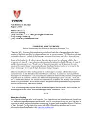
it reconnects <strong>the</strong> airflow just as if a physical tail existed. <strong>Trek</strong> has named this phenomenon <strong>the</strong> “virtual tail,” as illustrated below.<br />
Interestingly, <strong>the</strong> virtual tail is different than a traditional wake because it causes very little turbulent energy dissipation.<br />
Figure 15: CFD velocity vectors predicting <strong>the</strong> KVF’s late flow separation, virtual tail, and lack of wake turbulence.<br />
Comparatively, even one of <strong>the</strong> best traditional bicycle airfoils, such as that on <strong>the</strong> TTX, will have fairly early flow separation.<br />
Notes: 30 mph air velocity at 10˚ yaw.<br />
15