Airfoil Development for the Trek Speed Concept ... - Slowtwitch.com
Airfoil Development for the Trek Speed Concept ... - Slowtwitch.com
Airfoil Development for the Trek Speed Concept ... - Slowtwitch.com

Create successful ePaper yourself
Turn your PDF publications into a flip-book with our unique Google optimized e-Paper software.
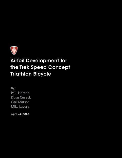
<strong>Airfoil</strong> <strong>Development</strong> <strong>for</strong><br />
<strong>the</strong> <strong>Trek</strong> <strong>Speed</strong> <strong>Concept</strong><br />
Triathlon Bicycle<br />
By: <br />
Paul Harder<br />
Doug Cusack<br />
Carl Matson<br />
Mike Lavery<br />
April 24, 2010<br />
1
Table of Contents<br />
3<br />
4<br />
4<br />
4<br />
5<br />
5<br />
6<br />
7<br />
7<br />
9<br />
9<br />
10<br />
10<br />
11<br />
12<br />
14<br />
15<br />
16<br />
16<br />
18<br />
18<br />
19<br />
20<br />
20<br />
20<br />
21<br />
21<br />
22<br />
23<br />
24<br />
25<br />
26<br />
27<br />
28<br />
Executive Summary<br />
Introduction<br />
1 Bicycle-Specific <strong>Airfoil</strong> <strong>Development</strong><br />
1.1 Why <strong>Airfoil</strong>s?<br />
1.2 Initial Literature Search<br />
1.3 <strong>Airfoil</strong> <strong>Development</strong>: February – October 2008<br />
1.3.1 Phase 1<br />
1.3.2 Phase 2<br />
1.3.3 Phase 3<br />
1.4 KVF Stiffness Benefits<br />
1.5 Kamm-Style <strong>Airfoil</strong>s in <strong>the</strong> Auto Industry<br />
2 Bicycle Aerodynamic <strong>Development</strong> & Testing<br />
2.1 Prototypes: November 2008 – February 2009<br />
2.2 Pro Team Bike: March – June 2009<br />
2.3 Production Bike: July 2009 – March 2010<br />
2.3.1 Mannequin Testing<br />
3 KVF Theory<br />
3.1 Validation of KVF Flow Behavior<br />
3.1.1 High <strong>Speed</strong> Camera Visualization<br />
3.1.2 Agreement with CFD Predictions<br />
3.1.3 Side-View Images<br />
4 Yaw<br />
Appendix<br />
1 Aerodynamic Drag in Cycling<br />
1.1 Flow Separation and Boundary Layers<br />
1.2 Implementation of Turbulence-Inducing Features (i.e. Dimples)<br />
2 The KVF’s Negative Drag (Thrust!)<br />
3 Misaligned <strong>Airfoil</strong>s<br />
4 <strong>Trek</strong>’s Wind Tunnel Test Standards<br />
5 O<strong>the</strong>r Common Tri-Bike <strong>Airfoil</strong>s<br />
6 Cervélo Wind Tunnel Data<br />
7 Specialized Wind Tunnel Data<br />
Glossary<br />
References
Executive Summary<br />
After years of research, development, and testing, <strong>Trek</strong> is confident to introduce <strong>the</strong> <strong>Speed</strong> <strong>Concept</strong> as <strong>the</strong> fastest production bicycle<br />
in <strong>the</strong> world. This claim is not made lightly – <strong>the</strong> <strong>Speed</strong> <strong>Concept</strong> is <strong>the</strong> final result of over 250 CFD simulations and 2,100 wind tunnel<br />
runs. At <strong>the</strong> core of its low-drag per<strong>for</strong>mance is <strong>the</strong> Kammtail Virtual Foil (KVF) tube shape, which itself is <strong>the</strong> result of a nine month<br />
project dedicated to low-speed airfoil development. The KVF is an unconventional aerodynamic shape proven to have incredibly low<br />
drag, with a light, stiff profile. In fact, <strong>the</strong> <strong>Speed</strong> <strong>Concept</strong>’s KVF tubes <strong>the</strong>mselves are proven to have negative drag (thrust) in a wide<br />
range of <strong>com</strong>mon wind conditions. <strong>Trek</strong> has gone to great lengths to accurately measure <strong>the</strong> aerodynamic drag of <strong>the</strong> <strong>Speed</strong> <strong>Concept</strong><br />
against that of <strong>the</strong> <strong>com</strong>petition, and <strong>the</strong> results speak <strong>for</strong> <strong>the</strong>mselves.<br />
Figure 1: Drag of several popular triathlon bikes.<br />
Notes: San Diego Low <strong>Speed</strong> Wind Tunnel. Without rider. Tares removed.<br />
3
Introduction<br />
<strong>Trek</strong> is dedicated to better products through genuine scientific research and innovation. True to this philosophy, <strong>the</strong> <strong>Speed</strong> <strong>Concept</strong>’s<br />
aerodynamics was developed from <strong>the</strong> ground up, using a fundamental scientific approach. This paper tells <strong>the</strong> story of <strong>the</strong> <strong>Speed</strong><br />
<strong>Concept</strong>’s aerodynamic development, focusing on <strong>the</strong> patent-pending breakthrough airfoil technology – <strong>the</strong> Kammtail Virtual Foil (KVF).<br />
To support this story, <strong>the</strong> Appendix includes additional studies, data, and discussions on general topics in bicycle aerodynamic <strong>the</strong>ory.<br />
1 Bicycle-Specific <strong>Airfoil</strong> <strong>Development</strong><br />
1.1 Why <strong>Airfoil</strong>s?<br />
Simply stated, as <strong>the</strong> bicycle moves <strong>for</strong>ward, air resists <strong>the</strong> motion of <strong>the</strong> frame tubes, resulting in aerodynamic drag. The amount of<br />
aerodynamic drag on a given tube is primarily determined by <strong>the</strong> tube’s cross-section. There<strong>for</strong>e, triathlon bicycle tube cross sections<br />
are designed using low-drag 2D airfoil shapes. Because <strong>the</strong>y are <strong>the</strong> building blocks which determine <strong>the</strong> bicycle’s overall aerodynamic<br />
potential, <strong>the</strong>se cross-sectional airfoil shapes were <strong>the</strong> sole focus of <strong>the</strong> first nine months of <strong>Speed</strong> <strong>Concept</strong> research & development.<br />
Figure 2: The <strong>Speed</strong> <strong>Concept</strong> with <strong>the</strong> 2D airfoil cross-sections of several tubesidentified in red.<br />
Note that <strong>the</strong> airfoil is defined in <strong>the</strong> horizontal direction of <strong>the</strong> wind (waterline plane).<br />
4
1.2 Initial Literature Search<br />
As in any scientific research project, <strong>the</strong> first step was to review any scientific literature available on <strong>the</strong> topic. After an exhaustive<br />
search, very little relevant literature was found. While general airfoils have been studied heavily throughout recent history, almost all<br />
such research has been directed towards high airspeed (75 mph to supersonic) aeronautical applications. For reasons discussed in <strong>the</strong><br />
next section, <strong>the</strong>se high-speed airfoils are nei<strong>the</strong>r practical nor effective on bicycles.<br />
A much smaller, though significant, amount of aerodynamic research has been conducted <strong>for</strong> automobiles. This research is again<br />
mostly irrelevant to bicycles due to <strong>the</strong> much higher speeds and thus very small yaw angles (yaw is described in Section 4). In addition,<br />
<strong>the</strong> parts of an automobile which are true airfoils are often asymmetric and designed to provide down-<strong>for</strong>ce. However, <strong>the</strong> overall<br />
automobile body itself experiences <strong>the</strong> same flow separation issues which are known to plague <strong>the</strong> low aspect ratio airfoils on current<br />
bicycles.<br />
Bicycles inhabit a small niche in aerodynamic science. There has been very little historical demand <strong>for</strong> such research because<br />
aerodynamic drag is of importance to very few devices which travel through air at 30 mph or less. Fluid dynamic behavior at such low<br />
speeds (low Reynolds Numbers) is notoriously difficult to study and predict [1, 2]. Fur<strong>the</strong>rmore, <strong>the</strong> stiffness and weight requirements<br />
of a bicycle create additional constraints. Finally, bicycles see much higher yaw angles than practically any o<strong>the</strong>r aerodynamic device<br />
because <strong>the</strong>y travel at speeds similar to <strong>com</strong>mon wind speeds.<br />
To cyclists looking to get an edge on <strong>the</strong> <strong>com</strong>petition, <strong>the</strong> lack of fundamental research in this subfield of aerodynamics is actually<br />
good news, as <strong>the</strong>re is still room <strong>for</strong> major advances in bicycle aerodynamics. <strong>Trek</strong> is at <strong>the</strong> <strong>for</strong>efront of this field, dedicating immense<br />
engineering resources towards true scientific research, not towards marketing hype.<br />
1.3 <strong>Airfoil</strong> <strong>Development</strong>: February – October 2008<br />
The lack of fundamental research of symmetric low-speed airfoils has left <strong>the</strong> bicycle industry grasping at straws. At worst, bicycle airfoil<br />
shapes are chosen because <strong>the</strong>y simply look unique or can be marketed as highly-engineered, though <strong>the</strong>y actually per<strong>for</strong>m poorly. At<br />
best, bicycle airfoil shapes are designed after <strong>the</strong> airfoils used in <strong>the</strong> aeronautical industry, such as <strong>the</strong> library of NACA airfoils. However,<br />
many of <strong>the</strong>se aeronautical airfoils do not work well <strong>for</strong> bicycles <strong>for</strong> several reasons. First, generally high aspect ratio (slender) airfoils<br />
would make very heavy and/or flexible bicycle tubes. While it is possible to manipulate <strong>the</strong> NACA system to obtain a<br />
symmetric low aspect ratio airfoil, <strong>the</strong> system was primarily designed <strong>for</strong> high aspect ratio, asymmetric flying wings. Second, it is well<br />
known that <strong>the</strong> effectiveness of an airfoil highly depends on <strong>the</strong> Reynolds Number at which it operates [2], and bicycles operate at<br />
much lower Reynolds Numbers than aircraft. Third, <strong>the</strong> aerodynamics governing aircraft differ significantly to ground vehicles, which are<br />
limited to motion in one direction, as discussed in Appendix 2.<br />
In early 2008, <strong>Trek</strong> engineers decided that <strong>the</strong> status quo had to change if bicycle aerodynamics were going to take any true scientific<br />
leap <strong>for</strong>ward. This leap would require <strong>the</strong> first fundamental study of low-speed airfoils specifically designed <strong>for</strong> bicycles, and <strong>Trek</strong><br />
was in <strong>the</strong> unique situation of having both <strong>the</strong> engineering resources and expertise to take on this historically neglected subset of<br />
aerodynamics. This project would fly <strong>com</strong>pletely under <strong>the</strong> radar within <strong>Trek</strong>. There would be no timelines, deadlines, or ties to o<strong>the</strong>r<br />
projects – this research would end only if and when true scientific discovery was made and would <strong>com</strong>pose of three phases:<br />
Phase 1: Develop a method <strong>for</strong> classifying and accurately testing airfoils using <strong>com</strong>putational fluid dynamics (CFD). Create<br />
a proprietary library of traditional airfoil geometries and drag data.<br />
Phase 2: Expand <strong>the</strong> CFD library to include non-traditional airfoil geometries. Consider no idea too wild to test and no<br />
traditional <strong>the</strong>ory too deeply-rooted to challenge.<br />
Phase 3: If Phases 1 or 2 resulted in true scientific breakthroughs, <strong>the</strong> most promising airfoil concepts would be refined and<br />
validated in <strong>the</strong> wind tunnel.<br />
5
1.3.1 Phase 1<br />
At <strong>the</strong> onset of <strong>the</strong> project, <strong>Trek</strong> engineers knew that most airfoil <strong>the</strong>ories and conventions that had been developed <strong>for</strong> <strong>the</strong> auto and<br />
aeronautical industries would not translate to bicycles. So, a new system <strong>for</strong> constructing and classifying airfoils was created. The<br />
defining parameters would be varied and tested in CFD, building a library of proprietary airfoil geometries and per<strong>for</strong>mance data. As<br />
a first step, a variety of CFD softwares and settings were tested in a wind tunnel validation study. In <strong>the</strong> end, <strong>Trek</strong>’s standard CFD<br />
method proved to be extremely accurate. This was not surprising since this method has been developed and refined over <strong>Trek</strong>’s 7<br />
years of in- house CFD testing.<br />
Figure 3: Validation of CFD results in <strong>the</strong> San Diego<br />
Low <strong>Speed</strong> Wind Tunnel.<br />
Left: One of several airfoil sections being tested.<br />
Right: Tare model being tested.<br />
As <strong>the</strong> library of proprietary airfoils was built, clear relationships were discovered relating key airfoil dimensions to aerodynamic drag.<br />
A portion of <strong>the</strong> data library is shown in <strong>the</strong> figure below. In this figure, <strong>the</strong> line colors represent one dimension, and <strong>the</strong> line styles<br />
represent a second dimension. Trends in drag are obvious across both dimensions, but <strong>the</strong> line-color dimension clearly has <strong>the</strong> more<br />
significant impact.<br />
Figure 4: The effects of two<br />
airfoil geometry parameters<br />
on drag. CFD data.<br />
6
<strong>Trek</strong>’s library of airfoil designs and aerodynamic per<strong>for</strong>mance data would eventually grow to include over 80 airfoil designs and 250<br />
individual CFD simulations. Following trends, such as those shown in <strong>the</strong> previous figure, this immense library pointed towards <strong>the</strong><br />
optimum bicycle airfoil designs. In addition, <strong>the</strong> analysis of <strong>the</strong> flow patterns within each CFD simulation revealed exactly why <strong>the</strong>se<br />
airfoils per<strong>for</strong>med so well.<br />
1.3.2 Phase 2<br />
The airfoils developed in phase 1 could have been leveraged to make a bicycle faster than <strong>the</strong> <strong>Trek</strong> TTX, <strong>the</strong> fastest bike <strong>Trek</strong> had ever<br />
tested in <strong>the</strong> wind tunnel. Despite this prospect of success, <strong>the</strong> study was expanded beyond traditional airfoil shapes. Using <strong>Trek</strong>’s<br />
highly-efficient CFD test method, <strong>the</strong>re was very little time penalty <strong>for</strong> exploring wild airfoil ideas. Anything was fair game, and after<br />
three months of exploration, one such wild idea gave a strange result – negative drag! While negative drag is <strong>the</strong>oretically possible<br />
(Appendix 2), it was such an extreme result that <strong>the</strong> engineers didn’t know whe<strong>the</strong>r to celebrate or start looking <strong>for</strong> a mistake in <strong>the</strong><br />
analysis. Of course, <strong>the</strong>re was no mistake, and <strong>the</strong> Kammtail Virtual Foil (KVF) was born.<br />
As was done <strong>for</strong> <strong>the</strong> traditional airfoil library, <strong>the</strong> key geometric parameters of <strong>the</strong> KVF were identified, and <strong>the</strong>ir effects on<br />
aerodynamic drag were studied in CFD. Over <strong>the</strong> next several months, a new library of over 50 KVF geometries and data was built.<br />
During this process, it was observed that <strong>the</strong> aerodynamic per<strong>for</strong>mance of KVF airfoils was significantly improved by even slight<br />
changes in geometry. Fur<strong>the</strong>rmore, <strong>the</strong> pitch orientation of <strong>the</strong> tube heavily dictates <strong>the</strong> relative per<strong>for</strong>mance of different KVF designs.<br />
As a result, <strong>Trek</strong> engineers have taken painstaking steps to fine-tune <strong>the</strong> geometries <strong>for</strong> optimum per<strong>for</strong>mance of each individual<br />
bicycle frame and <strong>for</strong>k tube. By nature, <strong>the</strong> KVF design must be highly-engineered, and casual knowledge of Kamm-style airfoil<br />
construction and <strong>the</strong>ory is not enough to design a high-per<strong>for</strong>ming KVF.<br />
1.3.3 Phase 3<br />
Although no mistakes were identified in <strong>the</strong> ongoing CFD analyses, <strong>the</strong> KVF airfoil results still seemed too good to be true. Be<strong>for</strong>e<br />
designing a bike around <strong>the</strong> KVF airfoil concept, a wind tunnel validation was warranted. In October 2008, <strong>Trek</strong> engineers took <strong>the</strong><br />
opportunity to test at <strong>the</strong> A2 Wind Tunnel <strong>for</strong> <strong>the</strong> first time.<br />
For <strong>the</strong>se tests, <strong>Trek</strong>’s in-house Prototype <strong>Development</strong> Lab CNC-machined <strong>the</strong> top four KVF shapes and <strong>the</strong> TTX down tube shape<br />
into solid aluminum tube sections. Each section was capped at both ends with an identical taper designed to reduce end-effects to a<br />
much smaller and more consistent contribution to <strong>the</strong> overall drag. These sections were tested across a wide range of pitch and yaw<br />
angles . The figure below shows <strong>the</strong> data <strong>for</strong> a vertical pitch angle.<br />
Figure 5: A2 Wind Tunnel data <strong>for</strong> airfoil<br />
sections tested at a vertical pitch angle.<br />
Notes: A2 Wind Tunnel. Tares not removed.<br />
7
As <strong>the</strong> data shows, <strong>the</strong> remarkable drag savings predicted in CFD were absolutely correct. In particular, KVF airfoils #3 and #5 had<br />
massive drag savings over <strong>the</strong> industry-leading TTX airfoil shape. These same airfoils were subsequently tested at <strong>the</strong> San Diego Low<br />
<strong>Speed</strong> Wind Tunnel on two occasions. The relative results varied slightly from those measured at <strong>the</strong> A2 Wind Tunnel, though <strong>the</strong><br />
overall story remained <strong>the</strong> same – incredible drag savings.<br />
After tare removal of <strong>the</strong> San Diego data, it was discovered that <strong>the</strong> KVF truly does have negative drag (thrust) at 10-17° yaw. This<br />
rare phenomenon is hard <strong>for</strong> <strong>the</strong> non-aerodynamicist to envision, but it is indeed possible as discussed in Appendix 2. In effect, <strong>the</strong><br />
airflow over a KVF tube actually propels <strong>the</strong> bicycle <strong>for</strong>ward! These results are unprecedented <strong>for</strong> airfoils designed <strong>for</strong> high stiffness<br />
and low weight. Plus, <strong>the</strong> vertical pitch angle is aerodynamically <strong>the</strong> worst-case scenario, and <strong>the</strong> data includes <strong>the</strong> drag of <strong>the</strong> airfoil<br />
section end caps. <strong>Trek</strong> immediately applied <strong>for</strong> a patent covering <strong>the</strong> use of KVF technology on bicycle frames, <strong>com</strong>ponents, and<br />
accessories.<br />
Figure 6: Top: Wind tunnel data showing <strong>the</strong> negative drag per<strong>for</strong>mance of<br />
two KVF designs at a vertical pitch angle. Bottom: Test images of an airfoil<br />
being tested at two different pitch angles. Notes: San Diego Low <strong>Speed</strong> Wind<br />
Tunnel. Tares removed (only <strong>the</strong> vertical struts and horizontal rod).<br />
8
1.4 KVF Stiffness Benefits<br />
In addition to its excellent aerodynamics, <strong>the</strong> KVF shape is very laterally and torsionally stiff. The chart below <strong>com</strong>pares <strong>the</strong> stiffness<br />
of <strong>the</strong> airfoils which were tested in <strong>the</strong> windtunnel, as <strong>com</strong>pared to <strong>the</strong> TTX traditional airfoil. Since stiffness trades off with wall<br />
thickness (i.e. weight) <strong>the</strong> KVF airfoil can be designed to be stiffer and/or lighter than a traditional airfoil.<br />
Table 1: Comparison of <strong>the</strong> moments of inertia (stiffness) of KVFs versus <strong>the</strong> TTX airfoil.<br />
Figure 7: Overlaid images of a traditional airfoil and<br />
a KVF, illustrating <strong>the</strong> added stiffness of <strong>the</strong> KVF.<br />
1.5 Kamm-Style <strong>Airfoil</strong>s in <strong>the</strong> Auto Industry<br />
Though <strong>Trek</strong>’s research of low-speed, large-yaw, symmetric airfoils was perhaps <strong>the</strong> first of its kind, <strong>the</strong> <strong>Speed</strong> <strong>Concept</strong> would not be<br />
<strong>the</strong> first ground vehicle to apply <strong>the</strong> concept of a truncated tail airfoil. In fact, <strong>the</strong> concept has been used by auto industry since <strong>the</strong><br />
1930s [3]. Today, many car body designs take advantage of <strong>the</strong> phenomenon to achieve high per<strong>for</strong>mance, such as <strong>the</strong> Mercedes<br />
Benz SLR, and efficiency, such as <strong>the</strong> Volkswagen L1. The L1 is claimed to be “<strong>the</strong> most efficient car in <strong>the</strong> world” [4] largely due to its<br />
0.195 drag coefficient [5].<br />
Figure 8: Left: Mercedes Benz SLR [6]. Right: Volkswagen L1.<br />
9
2 Bicycle Aerodynamic <strong>Development</strong> & Testing<br />
2.1 Prototypes: November 2008 – February 2009<br />
After almost a year of airfoil development, it was time to use <strong>the</strong>se building blocks to make <strong>the</strong> fastest bike in <strong>the</strong> world. <strong>Trek</strong>’s<br />
engineering and industrial design teams began work on a frame which incorporated <strong>the</strong> KVF, along with <strong>the</strong> o<strong>the</strong>r aerodynamic<br />
integration concepts which had been under development. KVF variations were carefully selected <strong>for</strong> each tube based on stiffness<br />
requirements and pitch angle-specific drag per<strong>for</strong>mance. Of course, it was still unknown how <strong>the</strong> KVF would per<strong>for</strong>m in a full bicycle<br />
system, and several additional questions remained, such as <strong>the</strong> ideal tube placements, orientations, transitions, relationships to <strong>the</strong><br />
wheels, etc.<br />
To answer <strong>the</strong>se questions, <strong>the</strong> aerodynamics of many prototype variations would need to be tested. Wind tunnel testing was chosen<br />
over CFD testing due to <strong>the</strong> many <strong>com</strong>plex flow interactions and moving parts of a <strong>com</strong>plete bicycle. An adjustable frame skeleton<br />
was developed <strong>for</strong> testing physical prototypes of each of design variation in <strong>the</strong> wind tunnel. This framework of adjustable steel beams<br />
was created by <strong>Trek</strong>’s in-house machinists. <strong>Trek</strong>’s in-house Prototype Lab <strong>the</strong>n created rapid-prototyped shells of <strong>the</strong> bicycle tubes<br />
using an Objet Connex 500. These shells could snap on and off of <strong>the</strong> framework, allowing quick modification of <strong>the</strong> prototype bike’s<br />
shape. While <strong>the</strong> use of adjustable prototypes well-established in <strong>the</strong> wind tunnel <strong>com</strong>munity, this system was made to be not only<br />
fully adjustable but also fully rideable by a pedaling cyclist.<br />
Figure 9: Left: The adjustable prototype partially assembled with plastic shells.<br />
Right: Adjustable prototype being ridden in <strong>the</strong> San Diego Low <strong>Speed</strong> Wind Tunnel.<br />
10
2.2 Pro Team Bike: March – June 2009<br />
During hundreds of wind tunnel runs studying various rapid-prototyped designs, <strong>the</strong> best design choices were discovered. <strong>Trek</strong>’s<br />
design teams went back to work, incorporating <strong>the</strong>se findings into one final bicycle concept. With a great deal of work from <strong>Trek</strong>’s<br />
manufacturing engineering team, OCLV molding lab, and test lab (all in Waterloo, WI), full-carbon team bikes were made <strong>for</strong> Chris<br />
Lieto to race at Ironman 70.3 Boise and <strong>the</strong>n <strong>for</strong> team Astana to race in <strong>the</strong> Tour de France. Of course, one carbon team bike would<br />
go back to <strong>the</strong> wind tunnel <strong>for</strong> a head-to-head test against <strong>the</strong> best <strong>the</strong> market had to offer.<br />
Figure 10: Head-to-head wind tunnel data <strong>for</strong> several popular triathlon bikes.<br />
Notes: <strong>Trek</strong>’s wind tunnel test standards are described in Appendix 4. The P4 was tested with<br />
its integrated aero bottle because this is its most aero configuration [21]. San Diego Low <strong>Speed</strong><br />
Wind tunnel. Without rider. Disc rear wheel and Hed 3 front wheel. Tares removed.<br />
The newly-named <strong>Speed</strong> <strong>Concept</strong> was in a class of its own. At 0˚ yaw, <strong>the</strong> P4 had a slight advantage (with integrated aero bottle),<br />
but <strong>the</strong> team <strong>Speed</strong> <strong>Concept</strong> was by far <strong>the</strong> fastest overall bike. Also note that over a large range of yaw angles <strong>com</strong>mon in cycling,<br />
<strong>the</strong> <strong>Trek</strong> TTX was second fastest (only to <strong>the</strong> team <strong>Speed</strong> <strong>Concept</strong>).<br />
11
2.3 Production Bike: July 2009 – March 2010<br />
<strong>Trek</strong> engineers would spend <strong>the</strong> next year refining <strong>the</strong> team <strong>Speed</strong> <strong>Concept</strong> design into <strong>the</strong> production <strong>Speed</strong> <strong>Concept</strong> found at<br />
<strong>Trek</strong> Dealers today. In fact, since <strong>the</strong> June 2009 wind tunnel tests, <strong>Trek</strong> has dedicated an additional 1,200 wind tunnel runs directly<br />
towards <strong>Speed</strong> <strong>Concept</strong> development and testing, bringing <strong>the</strong> total up to 2,100 runs. This ongoing development culminated in a<br />
final head-to-head showdown at <strong>the</strong> San Diego Low <strong>Speed</strong> Wind Tunnel in March 2010. This final data is shown in <strong>the</strong> figure below.<br />
Figure 11: Drag of several popular triathlon bikes.<br />
Notes: <strong>Trek</strong>’s wind tunnel test standards are described in Appendix 4. The P4 was tested with its integrated aero<br />
bottle because this is its most aero configuration [21]. The 2010 Felt B2 has <strong>the</strong> same frame and <strong>for</strong>k shape as <strong>the</strong><br />
Felt DA, so <strong>the</strong> drag is almost certainly <strong>the</strong> same [7]. The <strong>Speed</strong> <strong>Concept</strong> has replaced <strong>the</strong> TTX as <strong>Trek</strong>’s baseline<br />
test bike. San Diego Low <strong>Speed</strong> Wind tunnel. Without rider. Disc rear wheel and Bontrager Aeolus 9.0 front wheel.<br />
Tares removed.<br />
As can be seen, <strong>the</strong> <strong>Speed</strong> <strong>Concept</strong> OCLV had <strong>the</strong> least drag by a huge margin, with <strong>the</strong> <strong>Speed</strong> <strong>Concept</strong> TCT <strong>com</strong>ing in second<br />
overall. Over <strong>the</strong> entire yaw range, <strong>Speed</strong> <strong>Concept</strong> OCLV has an average of 91 grams less drag than <strong>the</strong> Cervélo P4, <strong>the</strong> closest<br />
overall <strong>com</strong>petitor. With an average of 22 grams less drag than <strong>the</strong> closest overall <strong>com</strong>petitor, <strong>the</strong> <strong>Speed</strong> <strong>Concept</strong> TCT was <strong>the</strong><br />
second fastest bike tested. At 15˚ of yaw (a fairly <strong>com</strong>mon condition – see Section 4), <strong>the</strong> <strong>Speed</strong> <strong>Concept</strong> OCLV and <strong>Speed</strong><br />
<strong>Concept</strong> TCT have 169 and 83 grams less drag than any o<strong>the</strong>r bike tested. Considering that in this configuration <strong>the</strong> <strong>Speed</strong><br />
<strong>Concept</strong>’s drag at 15˚ yaw is only 405 grams total, <strong>the</strong>se drag savings are immense.<br />
12
Relating drag savings to universally meaningful real-world values can be tricky. Conversions to seconds or watts savings require<br />
assumptions, speed, distance, and/or o<strong>the</strong>r sources of power loss like rolling resistance. However, <strong>the</strong>se assumed values are different<br />
<strong>for</strong> every individual cyclist. <strong>Trek</strong> engineers have discovered that <strong>the</strong> percentage of overall time saved due to a given drag savings is<br />
essentially independent of any o<strong>the</strong>r factors. So, anybody can simply multiply <strong>the</strong>ir total ride time by this percentage to determine<br />
<strong>the</strong>ir time savings (remember that 1% is actually 0.01). The percentage time savings of <strong>the</strong> <strong>Speed</strong> <strong>Concept</strong> OCLV over <strong>the</strong> best and<br />
worst-per<strong>for</strong>ming <strong>com</strong>petitors in <strong>the</strong> test group are shown in <strong>the</strong> left axis of <strong>the</strong> figures below. The right axis shows <strong>the</strong> time savings<br />
<strong>for</strong> an example case: 112 miles at an average of 20 mph (336 minute total ride time). Note that position will have <strong>the</strong> same effect as<br />
cyclist size. For a better idea of what yaw angles are typical in cycling, see Section 4.<br />
Figure 12: Time saved by <strong>the</strong> <strong>Speed</strong><br />
<strong>Concept</strong> OCLV over <strong>the</strong> Cervélo P4 and<br />
Felt B2 (same frame/<strong>for</strong>k shape as <strong>the</strong> Felt<br />
DA [7]). Of course, <strong>the</strong>se <strong>com</strong>parisons<br />
assume that <strong>the</strong> frame and <strong>for</strong>k are <strong>the</strong><br />
only things that change.<br />
13
2.3.1 Mannequin Testing<br />
Historically, nearly every time <strong>Trek</strong> engineers tested bikes alone, <strong>the</strong>y additionally tested with one or more trained test rider. Including<br />
a pedaling rider ensures that <strong>the</strong> test accounts <strong>for</strong> <strong>the</strong> air flow’s dynamic interaction, redirection, and blockage between <strong>the</strong> rider<br />
and bicycle. However, even when great care is taken to maximize repeatability, a human rider can potentially add significant amount<br />
of data uncertainty. Fur<strong>the</strong>rmore, <strong>the</strong> test procedure with a live rider takes four times longer than with a bike alone, and even <strong>the</strong><br />
best rider cannot consistently ride in <strong>the</strong> tunnel all day long. So, <strong>Trek</strong> engineers reviewed photos of triathletes at <strong>the</strong> 2009 Ironman<br />
World Championship and <strong>the</strong>n laser scanned an average-sized cyclist in what was determined to be a typical triathlon position. This<br />
scan was used to design and fabricate a fully-articulated, position-adjustable cycling mannequin, “Manny.” Manny proved to pedal<br />
smoothly and lifelike, providing data with an average uncertainty of only ±8 grams between duplicated tests.<br />
Figure 13: Left: Manny on a <strong>Speed</strong> <strong>Concept</strong> during a wind tunnel test.<br />
Right: Manny on a <strong>Speed</strong> <strong>Concept</strong> be<strong>for</strong>e a wind tunnel test (not yet pedaling).<br />
!<br />
The data with Manny turned out to be very enlightening and supported several <strong>the</strong>ories about <strong>the</strong> aerodynamic interaction between<br />
<strong>the</strong> cyclist and bicycle. Because <strong>the</strong> full-body pedaling mannequin and resulting data are proprietary to <strong>Trek</strong>’s tri bike testing and<br />
development, only <strong>the</strong> upper and lower limits of this data are being released. This data envelope illustrates that <strong>the</strong> benefits of <strong>the</strong><br />
<strong>Speed</strong> <strong>Concept</strong> remain when a pedaling cyclist is added to <strong>the</strong> system, without divulging all of <strong>the</strong> test findings. Note that although<br />
<strong>the</strong> Felt fell at <strong>the</strong> upper range of bikes that were tested, this test group obviously did not test all triathlon bikes.<br />
14<br />
Figure 14: Drag of <strong>the</strong> highest and lowest drag<br />
bikes with Manny <strong>the</strong> mannequin.<br />
Notes: <strong>Trek</strong>’s wind tunnel test standards are<br />
described in Appendix 4. San Diego Low <strong>Speed</strong><br />
Wind Tunnel. Disc rear wheel and Bontrager<br />
Aeolus 9.0 front wheel. Tares removed.
3 KVF Theory<br />
It is widely known that, within limits, high aspect ratio airfoils have lower drag than low aspect ratio airfoils [8]. For bicycles, <strong>the</strong> UCI<br />
sets a 3:1 aspect ratio maximum, so most major manufacturers generally adhere to this rule. However, even without <strong>the</strong> UCI rule, low<br />
aspect ratios are required to obtain sufficient weight and stiffness <strong>for</strong> use in bicycle tubes. If <strong>the</strong> airfoil width is decreased, it loses<br />
lateral stiffness, and if <strong>the</strong> airfoil length is increased, it gains weight without much gain in lateral stiffness (and <strong>the</strong> gain in vertical<br />
stiffness results in a harsher ride).<br />
So, <strong>the</strong> goal of bicycle airfoil design is to achieve <strong>the</strong> aerodynamic per<strong>for</strong>mance of a high aspect ratio airfoil within a <strong>com</strong>pact light/<br />
stiff profile. In <strong>the</strong> end, <strong>the</strong> solution is simple: use <strong>the</strong> portion of a high aspect ratio airfoil which works <strong>the</strong> hardest and throw away<br />
<strong>the</strong> rest.<br />
After hundreds of CFD simulations and wind tunnel runs, <strong>Trek</strong> engineers discovered that <strong>the</strong> per<strong>for</strong>mance benefits of a high aspect<br />
ratio airfoil are almost entirely due to <strong>the</strong> front portion of <strong>the</strong> airfoil. This part of <strong>the</strong> airfoil dictates flow separation behavior – <strong>the</strong><br />
most significant cause of aerodynamic drag on a traditional bicycle airfoil. Flow separation is when <strong>the</strong> bulk airflow detaches from<br />
airfoil wall; <strong>the</strong> result is a low pressure wake which pulls <strong>the</strong> tube backwards. Fur<strong>the</strong>rmore, drag is induced by turbulent energy<br />
dissipation in <strong>the</strong> separated wake region. Aerodynamic drag in cycling is fur<strong>the</strong>r discussed in Appendix 1.<br />
To minimize flow separation, <strong>the</strong> KVF incorporates <strong>the</strong> front portion of a high aspect ratio airfoil. To retain a stiff, light tube section,<br />
<strong>the</strong> tail of this high aspect ratio airfoil is truncated at a very specific location. The rear of <strong>the</strong> KVF was carefully designed such that<br />
it reconnects <strong>the</strong> airflow just as if a physical tail existed. <strong>Trek</strong> has named this phenomenon <strong>the</strong> “virtual tail,” as illustrated below.<br />
Interestingly, <strong>the</strong> virtual tail is different than a traditional wake because it causes very little turbulent energy dissipation.<br />
Figure 15: CFD velocity vectors predicting <strong>the</strong> KVF’s late flow separation, virtual tail, and lack of wake turbulence.<br />
Comparatively, even one of <strong>the</strong> best traditional bicycle airfoils, such as that on <strong>the</strong> TTX, will have fairly early flow separation.<br />
Notes: 30 mph air velocity at 10˚ yaw.<br />
15
With careful design, <strong>the</strong> KVF with a virtual tail realizes almost all of <strong>the</strong> drag savings of an ideal (higher) aspect ratio airfoil with a<br />
physical tail. The virtual tail <strong>com</strong>bines with <strong>the</strong> KVF to create a single effective airfoil of ideal aspect ratio, as shown in <strong>the</strong> figure<br />
below. Note that this figure is <strong>for</strong> 0˚ yaw, but flow separation (pressure drag) dramatically increases with yaw angle.<br />
Figure 16: Drag coefficient versus aspect ratio<br />
<strong>for</strong> traditional airfoils. Modified from [8].<br />
3.1 Validation of KVF Flow Behavior<br />
3.1.1 High <strong>Speed</strong> Camera Visualization<br />
While <strong>Trek</strong>’s CFD airfoil analysis techniques had been wind tunnel-validated to provide accurate <strong>com</strong>parative drag predictions, it was<br />
not yet certain that CFD fully-captured <strong>the</strong> qualitative flow characteristics. Particularly, <strong>the</strong> virtual tail phenomenon was yet to be<br />
proven in <strong>the</strong> real world. Fur<strong>the</strong>rmore, <strong>the</strong> all-important flow separation behavior is known to be difficult to accurately model in CFD,<br />
particularly <strong>for</strong> low Reynolds Number airfoils at large yaw angles [9]. So, an experiment was developed to validate <strong>the</strong>se behaviors in<br />
<strong>the</strong> real world.<br />
The goal of this ambitious experiment was to create images of <strong>the</strong> real-world flow around <strong>the</strong> KVF, which could be directly <strong>com</strong>pared<br />
to <strong>the</strong> CFD predictions previously shown in Figure 15. In <strong>the</strong> end, <strong>the</strong> experiment would utilize <strong>Trek</strong>’s Photron SA-3 high speed camera,<br />
a smoke wand, and four airfoil sections custom-designed <strong>for</strong> this visualization. This visualization method would prove to be both<br />
highly <strong>com</strong>plicated and successful, so <strong>the</strong> details will not be described here. The basic setup is shown in <strong>the</strong> figure below.<br />
16<br />
Figure 17: Smoke visualization test setup.<br />
Notes: For illustration purposes only – some details<br />
have been intentionally changed and hidden. San<br />
Diego Low <strong>Speed</strong> Wind Tunnel.
The results of this experiment were dramatic. Filmed at 7,500 frames per second, <strong>the</strong> airflow around four fundamental tube shapes at<br />
10˚ yaw was revealed in full detail. A still image from each of <strong>the</strong>se four videos is shown side-by-side in <strong>the</strong> figure below.<br />
Figure 18: Snapshot of <strong>the</strong> airflow around<br />
several airfoil shapes with <strong>the</strong> flow paths<br />
identified. Notes: 30 mph airflow in <strong>the</strong><br />
vertical direction. <strong>Airfoil</strong>s yawed 10˚ to <strong>the</strong><br />
right. Taken from a video filmed at 7,500<br />
frame per second. San Diego Low <strong>Speed</strong><br />
Wind Tunnel.<br />
In <strong>the</strong> previous figure, <strong>the</strong> wind direction is vertical from top to bottom, and each airfoil is yawed to 10˚ to <strong>the</strong> right, and <strong>the</strong> airspeed<br />
is 30 mph. The cross-sections were scaled such that each had <strong>the</strong> same lateral moment of inertia (lateral stiffness). The dashed lines<br />
indicate <strong>the</strong> air path across <strong>the</strong> trailing sidewall of <strong>the</strong> airfoil (<strong>the</strong> side on which flow separation occurs).<br />
As can be seen, <strong>the</strong> round cross-section (shape 1) has extremely early flow separation. In <strong>the</strong> video, <strong>the</strong> classic Kármán Vortex Street<br />
[10] of alternating eddies is clearly seen. The large turbulent wake results in extremely high drag.<br />
The traditional bicycle airfoil (shape 2) is a significant improvement over <strong>the</strong> cylinder. However, it still generates a significant wake<br />
because <strong>the</strong> flow separates from <strong>the</strong> trailing (right) wall. One indicator of this lack of flow attachment is that <strong>the</strong> wake does not turn<br />
in <strong>the</strong> direction of <strong>the</strong> airfoil. Instead, <strong>the</strong> air hits airfoil and spreads out, continuing in its original vertical direction.<br />
The KVF (shape 3) has much better separation characteristics, as <strong>the</strong> flow can be seen to stay attached along <strong>the</strong> entire length of<br />
<strong>the</strong> sidewall. Beyond <strong>the</strong> end of <strong>the</strong> KVF, <strong>the</strong> flow continues in a direction tangent to each sidewall and reconnects just as if a pointed<br />
physical tail existed, as illustrated in <strong>the</strong> figure below. This is <strong>the</strong> virtual tail! In <strong>the</strong> high speed video, <strong>the</strong> air inside <strong>the</strong> virtual tail is<br />
eerily slow-moving as <strong>the</strong> bulk flow streamlines around it.<br />
17<br />
Figure 19: Zoomed in region from Figure 18, with an<br />
identical outline around <strong>the</strong> virtual tail of shape 3 and<br />
<strong>the</strong> physical tail of shape 4.
3.1.2 Agreement with CFD Predictions<br />
These real-world flow patterns agree with CFD predictions. These CFD results are overlaid onto <strong>the</strong> smoke visualization results<br />
in <strong>the</strong> figure below.<br />
Figure 20: Overlay of CFD-predicted velocity<br />
vectors (from Figure 15) and real-world flow<br />
results (from Figure 18).<br />
3.1.3 Side-View Images<br />
In addition to <strong>the</strong> high speed video, standard video was taken from <strong>the</strong> side of each airfoil. This side-view fur<strong>the</strong>r illustrates <strong>the</strong><br />
dramatic difference in <strong>the</strong> amount of flow disruption (i.e. flow separation and turbulence, thus drag) generated by each airfoil.<br />
The figure below <strong>com</strong>pares <strong>the</strong> round (shape #1) and KVF (shape #3) cross-sections.<br />
Figure 21: Side view images of <strong>the</strong> round<br />
(top, #1) and KVF (bottom, #3), illustrating<br />
<strong>the</strong> dramatic difference in wake size.<br />
18
4 Yaw<br />
Yaw is angle between <strong>the</strong> total airspeed vector (apparent wind) and <strong>the</strong> direction of bicycle motion. In cycling, some amount of yaw<br />
almost always exists, since <strong>the</strong> wind speed is very rarely zero, and <strong>the</strong> cycling direction very rarely aligns perfectly with <strong>the</strong> wind<br />
direction. As is shown in <strong>the</strong> following figure, <strong>the</strong> yaw angle is determined by <strong>the</strong> cyclist’s speed, wind speed, and wind direction.<br />
Figure 22: Vector diagram of <strong>the</strong> yaw angle.<br />
Bicycles see much higher yaw angles than practically any o<strong>the</strong>r aerodynamic device because <strong>the</strong>y travel at speeds similar to <strong>com</strong>mon<br />
wind speeds. For example, <strong>for</strong> a cyclist riding at 20 mph, it takes a side wind of only 5.4 mph to generate a yaw angle of 15°. The<br />
yaw angles <strong>for</strong> a range of <strong>com</strong>mon side wind conditions are tabulated <strong>the</strong> figure below. A cyclist can use this figure to look up his/<br />
her riding speed (horizontal axis) and find <strong>the</strong> corresponding yaw angle (vertical axis) <strong>for</strong> a wide range of side wind speeds (multiple<br />
curves). Note that <strong>the</strong> average wind speeds along <strong>the</strong> Ironman World Championship course in Hawaii typically exceed 20 mph,<br />
particularly on <strong>the</strong> north side of <strong>the</strong> island [11]. As was seen in <strong>the</strong> wind tunnel data, <strong>the</strong> KVF and <strong>Speed</strong> <strong>Concept</strong> were designed to<br />
per<strong>for</strong>m particularly well at yaw.<br />
Figure 23: Yaw angles <strong>for</strong> a wide range<br />
of rider velocity (horizontal axis) and side<br />
wind speeds (curves).<br />
19
APPENDIX<br />
1 Aerodynamic Drag in Cycling<br />
Aerodynamic drag generally has two <strong>com</strong>ponents: pressure drag and skin friction drag. In cycling, pressure drag is caused by flow<br />
separation and <strong>the</strong> resulting low pressure wake behind <strong>the</strong> airfoil. The pressure differential from <strong>the</strong> front to <strong>the</strong> rear of <strong>the</strong> airfoil<br />
creates a <strong>for</strong>ce in <strong>the</strong> opposite direction to <strong>the</strong> airfoil’s motion (think of a vacuum sucking <strong>the</strong> rear of <strong>the</strong> airfoil backwards.) Flow<br />
separation also generates vortices and/or turbulence, both additional sources of energy dissipation. Skin friction drag is a <strong>for</strong>ce caused<br />
by <strong>the</strong> air traveling (shearing) across <strong>the</strong> skin of <strong>the</strong> airfoil.<br />
1.1 Flow Separation and Boundary Layers<br />
Traditional bicycle airfoils are extremely susceptible to flow separation, resulting in very high pressure drag [12, 13], as was illustrated<br />
in Figures 15 and 18. One way to delay flow separation (make <strong>the</strong> separation point occur far<strong>the</strong>r towards <strong>the</strong> tail of <strong>the</strong> airfoil) is to<br />
turn <strong>the</strong> boundary layer from laminar to turbulent. A turbulent boundary layer has more momentum and thus resists separating from<br />
<strong>the</strong> airfoil wall [8], as shown in <strong>the</strong> figure below. A laminar boundary layer can be turned turbulent using various turbulence-inducing<br />
features, such as dimples.<br />
Figure 24: Laminar and turbulent<br />
boundary layer profiles [8].<br />
However, flow separation is a symptom of an inherently high-drag airfoil. While a turbulent boundary layer might reduce pressure<br />
drag, it will increase skin friction drag [14]. In cases where <strong>the</strong> flow separation (pressure drag) is severe enough, <strong>the</strong> tradeoff results<br />
in a net reduction of drag. Obviously, an airfoil which can avoid this tradeoff altoge<strong>the</strong>r is ideal. The KVF was designed to behave like<br />
a large aspect ratio airfoil with very little or no flow separation. So, <strong>the</strong> KVF minimizes pressure drag without <strong>the</strong> aid of a turbulent<br />
boundary layer (high shear drag), resulting in <strong>the</strong> lowest possible total drag.<br />
20
1.2 Implementation of Turbulence-Inducing Features (i.e. Dimples)<br />
Logically, in order to delay flow separation, <strong>the</strong> boundary layer must be turned turbulent upstream from <strong>the</strong> laminar boundary layer<br />
separation point, as shown in <strong>the</strong> figure below. So, any turbulence-inducing feature located downstream from <strong>the</strong> separation point<br />
per<strong>for</strong>ms no practical function, and only has <strong>the</strong> potential to create unnecessary skin friction drag or turbulence. A golf ball is only<br />
dimpled across its entire surface to account <strong>for</strong> every possible ball orientation. Since <strong>the</strong> relative-wind orientation of bicycle tubes and<br />
<strong>com</strong>ponents (even those rotating) is fairly limited, <strong>the</strong> functionality of turbulence-inducing features is limited to a single specific area.<br />
As previously mentioned, <strong>the</strong> lowest possible drag is achieved when flow separation is avoided without <strong>the</strong> aid of any turbulenceinducing<br />
features.<br />
Figure 25: Flow around a smooth sphere (top) and around <strong>the</strong><br />
same sphere with a turbulence-inducing feature upstream<br />
from <strong>the</strong> laminar boundary layer separation point [16]. This<br />
is why golf balls are dimpled [15].<br />
2 The KVF’s Negative Drag (Thrust!)<br />
Because flying devices are not restricted to travel in a predetermined direction, airfoil aerodynamic <strong>for</strong>ces are traditionally measured<br />
in <strong>the</strong> axes parallel (drag) and perpendicular (lift) to <strong>the</strong> wind. In contrast, bicycles are on wheels which limit <strong>the</strong>ir motion to a single<br />
direction. While this distinction is seemingly trivial, it results in a whole different set of aerodynamic rules.<br />
In cycling <strong>the</strong> aerodynamic <strong>for</strong>ces are measured in <strong>the</strong> bike-axes, not <strong>the</strong> wind-axes. The reason is simple: it is <strong>the</strong> aerodynamic <strong>for</strong>ce<br />
<strong>com</strong>ponent in <strong>the</strong> direction of bicycle motion (drag) which consumes energy. The rest of <strong>the</strong> aerodynamic <strong>for</strong>ce – <strong>the</strong> <strong>com</strong>ponent in<br />
<strong>the</strong> direction perpendicular to bicycle motion – consumes no energy because <strong>the</strong> wheels restrict all motion in this direction. Stated<br />
ma<strong>the</strong>matically, <strong>the</strong> distance traveled in this direction is zero, and work (energy) is <strong>the</strong> product of <strong>for</strong>ce and distance.<br />
21
As a result, <strong>the</strong> aerodynamic rules governing cycling are most similar to those governing sailing. In sailing it is possible to obtain<br />
<strong>for</strong>ward thrust, even when traveling nearly directly into <strong>the</strong> wind. Like <strong>the</strong> centerboard of a sailboat, <strong>the</strong> wheels of a bicycle redirect<br />
<strong>the</strong> lift <strong>for</strong>ce in <strong>the</strong> wind-axes into a thrust <strong>for</strong>ce in <strong>the</strong> direction of bicycle (or boat) motion. However, <strong>the</strong> drag <strong>for</strong>ce in <strong>the</strong> wind-axes<br />
still contributes to a drag <strong>for</strong>ce in <strong>the</strong> bicycle direction. For traditional bicycle airfoils, <strong>the</strong> wind-axes lift <strong>for</strong>ce is much smaller than<br />
<strong>the</strong> wind-axes drag <strong>for</strong>ce, resulting in a net drag <strong>for</strong>ce in <strong>the</strong> bicycle direction. In contrast, <strong>the</strong> KVF has an extremely high lift to drag<br />
ratio in <strong>the</strong> wind-axes, allowing it to achieve a net thrust in <strong>the</strong> bicycle direction, just like a sailboat. This result is somewhat counterintuitive<br />
and unprecedented <strong>for</strong> bicycle airfoils, so an illustration is provided in <strong>the</strong> figure below.<br />
Figure 26: Diagram illustrating a case where<br />
negative drag occurs (in <strong>the</strong> bicycle-axes).<br />
It is also possible to obtain wind-axis lift by simply creating more side (sail-like) surface on <strong>the</strong> bicycle system. However, this added<br />
surface <strong>com</strong>es at <strong>the</strong> penalty of weight. Due to cross-wind stability concerns, side surfaces must be carefully designed into a bicycle<br />
system. The most stable location <strong>for</strong> such surface is low and rearward, making <strong>the</strong> rear disc wheel a popular choice.<br />
3 Misaligned <strong>Airfoil</strong>s<br />
<strong>Trek</strong> has received questions about <strong>the</strong> effect of misaligning an airfoil from <strong>the</strong> bike-axis, such as a handlebar which is not perfectly<br />
horizontal, whe<strong>the</strong>r intentionally or not. A well-designed airfoil will have very low <strong>for</strong>ce (drag) in <strong>the</strong> major chord direction and, as a<br />
natural result, very high <strong>for</strong>ce (lift) in <strong>the</strong> minor chord direction. For maximum efficiency, <strong>the</strong> direction of bicycle motion should align<br />
with <strong>the</strong> direction of minimum <strong>for</strong>ce (and <strong>the</strong>re<strong>for</strong>e with <strong>the</strong> airfoil).<br />
Although <strong>the</strong> wind tunnel measures <strong>the</strong> lift and drag <strong>for</strong>ces in <strong>the</strong> airfoil-axes, <strong>the</strong>se <strong>for</strong>ces are easily trans<strong>for</strong>med into <strong>the</strong> wind-axis,<br />
which now be<strong>com</strong>es <strong>the</strong> bike-axis. This trans<strong>for</strong>mation, along with an adjustment to ensure equivalent wind speed <strong>for</strong> each data<br />
point, allows a study of airfoil yaw angles to be converted into a study of airfoil misalignment angles. In o<strong>the</strong>r words, think of <strong>the</strong><br />
direction of bicycle motion as always facing straight into <strong>the</strong> wind in <strong>the</strong> wind tunnel. Then, as <strong>the</strong> airfoil is rotated, this rotation can<br />
be thought of as misalignment from <strong>the</strong> bicycle-axis instead of yaw.<br />
22
The effect of misalignment of <strong>the</strong> #3 KVF trial from Figure 6 is shown in <strong>the</strong> figure below. This data proves that any misalignment will<br />
increase drag, but beyond 12.5˚ <strong>the</strong> drag penalty is particularly severe. For <strong>the</strong>se reasons, <strong>the</strong> <strong>Speed</strong> <strong>Concept</strong> handlebar is designed to<br />
eliminate <strong>the</strong> possibility of misalignment.<br />
Figure 27: Percentage<br />
drag increase due to airfoil<br />
misalignment to <strong>the</strong> bike-axis.<br />
4 <strong>Trek</strong>’s Wind Tunnel Test Standards<br />
To make <strong>the</strong> most precise and objective wind tunnel measurements possible, <strong>Trek</strong> engineers strictly adhere to a set of best practices<br />
developed over <strong>Trek</strong>’s 11 years of wind tunnel testing. Primarily, in each head to head test, every possible aspect of each bike is kept<br />
<strong>the</strong> same. This includes all non-proprietary <strong>com</strong>ponents (wheels, tires, handlebar, shift/brake levers, stem, saddle, brakes, derailleurs,<br />
crank, cassette, etc.) and all adjustments (saddle height, saddle setback, saddle angle, handlebar location, handlebar angle, cable<br />
routing, etc.). Bicycles are tested with manufacturer’s proprietary <strong>com</strong>ponents (integrated cranks, brakes, handlebars, waterbottles,<br />
stems, seatposts, etc.) where standard <strong>com</strong>ponents can not be installed without modification. In addition, <strong>Trek</strong> will only put headto-head<br />
bike data on <strong>the</strong> same plot if it was collected in <strong>the</strong> same test session. Due to increased uncertainty, data is not necessarily<br />
<strong>com</strong>parable from one test session to <strong>the</strong> next. Instead of using old data, <strong>Trek</strong> spends <strong>the</strong> extra time and money to repeat tests and<br />
ensure <strong>com</strong>parable data. Finally, <strong>the</strong>re are safeguards built into <strong>Trek</strong>’s test procedure to ensure reliable, consistent results. Below is<br />
an example image of <strong>the</strong> standard bike setup from <strong>the</strong> June 2009 head-to-head wind tunnel tests including <strong>the</strong> team <strong>Speed</strong> <strong>Concept</strong>.<br />
23<br />
Figure 28: General setup from <strong>the</strong> June 2009 head-to-head<br />
wind tunnel tests. Notes: Team <strong>Speed</strong> <strong>Concept</strong> shown. Wheels<br />
would be spinning during <strong>the</strong> actual test. Bicycle yaw rotation is<br />
counterclockwise, such that <strong>the</strong> wind hits <strong>the</strong> drive side of <strong>the</strong><br />
bicycle. San Diego Low <strong>Speed</strong> Wind Tunnel.
For <strong>the</strong> March 2010 head-to-head tests at <strong>the</strong> San Diego Low <strong>Speed</strong> Wind Tunnel, <strong>the</strong> <strong>com</strong>petitor frameset sizes were chosen based on a<br />
nearest match to <strong>the</strong> Medium size <strong>Speed</strong> <strong>Concept</strong> in terms of frame stack and reach. Saddle height and setback were held constant. On<br />
every bike except <strong>the</strong> Felt B2, <strong>the</strong> mannequin’s armrest stack and reach were replicated to within a few millimeters with a <strong>com</strong>bination of<br />
Bontrager Race X Lite stems and <strong>the</strong> minimum required amount of steer tube spacers. The Felt’s stock proprietary stem system was able<br />
to replicate <strong>the</strong> position without modification. Bontrager’s Race X Lite Bullhorn and Race X Lite clip-on hardware were used with Race XXX<br />
Lite ski extensions and Team-only armrests (without pads) on all bikes o<strong>the</strong>r than <strong>the</strong> <strong>Speed</strong> <strong>Concept</strong> OCLV as a best approximation of <strong>the</strong><br />
cockpit adjustment range offered by <strong>the</strong> new SC RXL Aerobar system.<br />
!<br />
Table 2: Frame size, stem, and spacer<br />
configurations <strong>for</strong> <strong>com</strong>parable armrest<br />
position. Notes: SC RXL stem dimensions<br />
are [reach]x[stack], both in mm, and<br />
spacers <strong>for</strong> <strong>the</strong> SC RXL aerobar system are<br />
located between <strong>the</strong> base bar and armrests.<br />
Common <strong>com</strong>ponents installed on all bikes included: Shimano BB, crankset, cassette and shift levers, chain tensioner in place of <strong>the</strong> front<br />
derailleur, Bontrager Race X Lite Pro saddle, Bontrager RXL aero brake levers, Bontrager 5mm brake housing and 4mm shift housing, Zipp<br />
dimpled rear disk wheel, and Bontrager Aeolus 9.0 front wheel. A Cane Creek headset topcap was also <strong>com</strong>mon except on <strong>the</strong> <strong>Speed</strong><br />
<strong>Concept</strong> OCLV and Felt B2.<br />
5 O<strong>the</strong>r Common Tri-Bike <strong>Airfoil</strong>s<br />
The tri-bicycle marketplace is flooded with a variety of cross-sectional tube shapes which are marketed as highly-aerodynamic airfoils.<br />
<strong>Trek</strong> engineers recently toured several tri-shops and were astonished to find that almost all of <strong>the</strong>se airfoils, while likely interpreted as highly<br />
streamlined to <strong>the</strong> non-engineer, are in reality non-aerodynamic. The average triathlete relies on what each brand claims, ei<strong>the</strong>r directly<br />
through marketing or indirectly through a salesperson. Of course, every brand will claim to have <strong>the</strong> most aero tube shapes, yet only one can<br />
be correct. So, <strong>Trek</strong> engineers decided to objectively calculate <strong>the</strong> drag of a variety of popular airfoil styles with <strong>the</strong>ir validated CFD analysis<br />
method, as shown in Figure 29.<br />
As was found in <strong>the</strong> wind tunnel (Figure 6), <strong>the</strong> KVF was predicted to have slightly negative drag at 10˚ yaw. All of <strong>the</strong> o<strong>the</strong>r shapes exhibit<br />
some amount of flow separation, resulting in much higher drag. Figure 30 depicts <strong>the</strong> velocity contours around each airfoil. The separation<br />
points and resulting wakes are clearly visible as <strong>the</strong> blue, low velocity regions. Clearly, many “airfoils” are chosen without regard <strong>for</strong> true<br />
aerodynamic science. While <strong>the</strong>se are perhaps not all exact replicas of <strong>the</strong> airfoils found on any given bike, this study demonstrates <strong>the</strong><br />
general ineffectiveness of <strong>the</strong>se families of airfoils.<br />
Figure 29: CFD-predicted drag of various tube crosssections<br />
at 10˚ yaw and 30 mph. Notes: To ensure a level<br />
playing field, each of <strong>the</strong>se airfoils was scaled such that<br />
it has exactly <strong>the</strong> same lateral stiffness. 450 mm is about<br />
<strong>the</strong> length of a down tube or seat tube.<br />
24<br />
<strong>Trek</strong> KVF<br />
Traditional <strong>Airfoil</strong> (TTX)<br />
Diamond<br />
Convex Radius Nose<br />
Blunter Diamond<br />
Round<br />
Concave Radius Nose
Figure 30: Velocity contours,<br />
showing <strong>the</strong> wakes and flow<br />
separation points. Note<br />
that <strong>the</strong> round shape has an<br />
unsteady solution, including<br />
Kármán Vortex Street [10].<br />
6 Cervélo Wind Tunnel Data<br />
Cervélo has released head-to-head wind tunnel test data <strong>for</strong> a wide variety of bikes [17]. Since each manufacturer may test with different<br />
protocols, frame sizes, wheels, and <strong>com</strong>ponents, it is not scientifically valid to <strong>com</strong>bine this data with <strong>Trek</strong>’s data. However, in light of <strong>Trek</strong>’s<br />
recent data, three interesting observations can be made. First, <strong>the</strong> Felt DA’s drag fell in <strong>the</strong> middle of <strong>the</strong> group of <strong>the</strong> bikes Cervélo tested<br />
but was <strong>the</strong> slowest bike that <strong>Trek</strong> tested in Figure 11 (same frame/<strong>for</strong>k shape as <strong>the</strong> 2010 Felt B2 [7]). <strong>Trek</strong> generally focuses on testing<br />
against only <strong>the</strong> fastest bikes available, so <strong>the</strong> Cervélo data reflects a broader cross-section of bike aerodynamic per<strong>for</strong>mance available<br />
to <strong>the</strong> triathlon market. Second, <strong>Trek</strong>’s tests found <strong>the</strong> P4 to cross above <strong>the</strong> P3 at yaw angles of about 13˚ and greater (Figure 11). It is not<br />
certain if this agrees with Cervélo’s data because <strong>the</strong>y did not publish P4 data above 12.5˚ yaw. Third, Cervélo’s graph does not provide<br />
data <strong>for</strong> <strong>the</strong> <strong>Trek</strong> TTX, though it was at <strong>the</strong> time known to be one of <strong>the</strong> lowest drag bikes, according to historical <strong>Trek</strong> data [18], historical<br />
Cervélo data [19], and <strong>Trek</strong>’s June 2009 data in Figure 10.<br />
Figure 31: Head-to-head wind<br />
tunnel test data released by<br />
Cervélo in 2009 [17].<br />
25
7 Specialized Wind Tunnel Data<br />
While <strong>Trek</strong> has not yet tested <strong>Speed</strong> <strong>Concept</strong> directly against <strong>the</strong> Specialized Shiv or Giant Trinity Advanced, Specialized has released<br />
head-to-head wind tunnel data <strong>for</strong> <strong>the</strong>se two <strong>com</strong>peting bikes along with <strong>the</strong> Cervélo P4 [22].<br />
Figure 32: Head-to-head wind tunnel test data released by Specialized in 2010 [22].<br />
26
Glossary<br />
** Note: terms are terms defined as <strong>the</strong>y are used in this paper. **<br />
<strong>Airfoil</strong>:<br />
Aspect Ratio: <br />
Boundary Layer:<br />
CFD:<br />
The 2D cross-section of a bicycle tube. Typically, this is a streamlined aerodynamic shape defined in <strong>the</strong><br />
waterline plane.<br />
The ratio of <strong>the</strong> major chord (length) to <strong>the</strong> minor chord (width) of a 2D airfoil. This is a departure from <strong>the</strong><br />
aeronautical industry, which defines aspect ratio using <strong>the</strong> wingspan.<br />
The layer of slower-moving fluid immediately next to <strong>the</strong> airfoil wall.<br />
Computer software which simulates fluid flows and can be used to predict aerodynamics. Stands <strong>for</strong><br />
Computational Fluid Dynamics.<br />
Major & Minor Chord:<br />
End-Effects: The flow across <strong>the</strong> end of a finite-length airfoil section which generally increases drag and reduces lift [8].<br />
KVF:<br />
NACA <strong>Airfoil</strong>s:<br />
Pitch:<br />
<strong>Trek</strong>’s trade name <strong>for</strong> its breakthrough airfoil design which, at a low aspect ratio, achieves nearly all of <strong>the</strong><br />
immense aerodynamic and stiffness benefits of an o<strong>the</strong>rwise impractical high aspect ratio airfoil. Stands <strong>for</strong><br />
Kammtail Virtual Foil.<br />
An aircraft wing airfoil designation system first established in <strong>the</strong> 1930s by <strong>the</strong> National Advisory Committee<br />
<strong>for</strong> Aeronautics [20].<br />
The vertical angle of tilt of a <strong>com</strong>ponent. For example, a down tube has a nearly 45˚ pitch.<br />
Reynolds Number: A dimensionless number often used to determine <strong>the</strong> similarity between different flow scenarios. Since <strong>the</strong><br />
Reynolds Number increases with both flow speed and object size, it is much higher <strong>for</strong> aircraft than bicycles.<br />
Stack and Reach: A measurement system proposed and popularized by Dan Empfield of <strong>Slowtwitch</strong>.<strong>com</strong> which focuses on <strong>the</strong><br />
vertical height (stack) and horizontal distance (reach) from <strong>the</strong> bottom bracket of a reference point at <strong>the</strong> front<br />
end of a bicycle. The most <strong>com</strong>mon reference point <strong>for</strong> frames is <strong>the</strong> top of <strong>the</strong> headtube.<br />
Tare Removal:<br />
The wind tunnel measures <strong>the</strong> drag of both <strong>the</strong> bike and <strong>the</strong> structures which hold <strong>the</strong> bike in place. To obtain <strong>the</strong><br />
drag of <strong>the</strong> bike only, <strong>the</strong> drag of <strong>the</strong> test structures alone are measured in a separate test and subtracted out. This<br />
method is standard in wind tunnel testing; however, it is not perfectly accurate because it does not account <strong>for</strong> any<br />
interactions or blockages between <strong>the</strong> test structure and bicycle. Since removing <strong>the</strong> tare does not change <strong>the</strong> drag<br />
difference between of any two bikes, it is an optional step. However, tared data provides a better measurement of<br />
<strong>the</strong> percentage difference.<br />
Traditional <strong>Airfoil</strong>: A teardrop-like shape with a pointed or generally tapered tail.<br />
27
Glossary<br />
** Note: terms are terms defined as <strong>the</strong>y are used in this paper. **<br />
Waterline:<br />
Windtunnel Run:<br />
Yaw:<br />
A plane parallel with <strong>the</strong> ground which slices through a bicycle tube (envision <strong>the</strong> surface of water if <strong>the</strong> tube were<br />
partially submerged.) This is <strong>the</strong> direction of air travel, and thus determines <strong>the</strong> effective airfoil that <strong>the</strong> air sees. A<br />
waterline cross section is shown in Figure 2.<br />
The measurement of <strong>the</strong> aerodynamic <strong>for</strong>ces at a given yaw angle (averaged over fifteen seconds to one minute,<br />
depending on <strong>the</strong> situation). A typical bicycle test consists of about six runs over a range of yaw angles. A wind tunnel<br />
session consists of many bicycle tests both with and without a rider (pedaling mannequin).<br />
The angle between <strong>the</strong> total airspeed vector and <strong>the</strong> direction of bicycle motion.<br />
References<br />
[1] Hepperle, Martin. Aerodynamics <strong>for</strong> Model Aircraft.<br />
http://www.mh-aerotools.de/airfoils/methods.htm (2007).<br />
[2] Lissaman, P. B. S. Low-Reynolds-Number <strong>Airfoil</strong>s. Annual Review of Fluid Mechanics, 15:223-239 (1983).<br />
[3] Ziemnowicz, Christoper. The Origin of <strong>the</strong> Kammback Design. (2004)<br />
http://academics.concord.edu/chrisz/hobby/80-AMXitems/In<strong>for</strong>mation/production/KammbackStory.html<br />
[4] Williams, Stephen. VW Says L1 Hybrid Is ‘Most Efficient’ Car in <strong>the</strong> World. New York Times Online (2009) http://wheels.<br />
blogs.nytimes.<strong>com</strong>/2009/09/15/vw-says-l1-hybrid-is-most-efficient-car-in-<strong>the</strong>-world/<br />
[5] Pulman, Ben. VW L1 Diesel-Hybrid <strong>Concept</strong> at 2009 Frankfurt Motor Show. Car Magazine (2009) http://www.<br />
carmagazine.co.uk/News/Search-Results/First-Official-Pictures/VW-L1-diesel-hybrid-concept-at-2009-Frankfurt-motor-show/<br />
[6] Deppe, Philipp. The “large wind tunnel” in Untertürkheim.<br />
(2010) http://eblog.mercedes-benz-passion.<strong>com</strong>/2010/01/<strong>the</strong>-large-wind-tunnel-in-unterturkheim/<br />
[7] Empfield, Dan. Felt’s Tri Bikes <strong>for</strong> 2008. <strong>Slowtwitch</strong> Product Reviews (2008) http://www.slowtwitch.<strong>com</strong>/Products/Felt_s_<br />
tri_bikes_<strong>for</strong>_2008_280.html<br />
[8] Shames, Irving, H. Mechanics of Fluids, 4th ed. McGraw Hill (2003).<br />
[9] Eisenbach, Sven and Friedrich, Rainer. Large-eddy simulation of flow separation on an airfoil at a high angle of attack and<br />
Re = 105 using Cartesian grids. Theoretical and Computational Fluid Dynamics 22(3-4):213-225 (2008).<br />
[10] Panton, Ronald L. In<strong>com</strong>pressible Flow, 3rd ed. John Wiley & Sons, Inc. (2005).<br />
[11] Wind Energy Resource Data. Hawaii Department of Business, Economic <strong>Development</strong> and Tourism. http://hawaii.gov/dbedt/ert/<br />
winddata/ (Accessed April 2010).<br />
[12] efluids Bicycle Aerodynamics – Lift and Stall. http://www.efluids.<strong>com</strong>/efluids/bicycle/bicycle_pages/lift_stall.jsp<br />
28
[13] efluids Bicycle Aerodynamics – Drag of Blunt and Streamlined Bodies. http://www.efluids.<strong>com</strong>/efluids/bicycle/bicycle_pages/<br />
blunt.jsp<br />
[14] Celli, Vittorio. Boundary Layer Separation and Pressure Drag. University of Virginia (1997) http://galileo.phys.virginia.edu/<br />
classes/311/notes/fluids2/node11.html<br />
[15] efluids Bicycle Aerodynamics – Golf Balls, Cricket Balls, and Tennis Balls. http://www.efluids.<strong>com</strong>/efluids/bicycle/bicycle_pages/<br />
sportsballs.jsp<br />
[16] Whitt, Frank R. and Wilson, David G. Bicycling Science, 2nd ed. The MIT Press (1982).<br />
[17] Wind Tunnel Data Released at <strong>the</strong> Cervélo Brain Bike Dealer Event, which has been archived at http://<strong>for</strong>um.slowtwitch.<strong>com</strong>/<br />
g<strong>for</strong>um.cgi?do=post_view_flat;post=2009701<br />
[18] <strong>Trek</strong> Bicycles Wind Tunnel Investigation. (2007) http://www.slowtwitch.<strong>com</strong>/images/<strong>Trek</strong>whitepaper1.pdf<br />
[19] Wind Tunnel Data Released by Cervélo, which has been archived at http://i33.tinypic.<strong>com</strong>/25jjszm.jpg (Accessed April 2010).<br />
[20] Scott, Jeff. NACA <strong>Airfoil</strong> Series. Aerospaceweb.org (2001). http://www.aerospaceweb.org/question/airfoils/q0041.shtml<br />
[21] Leijonberg, Jonathan. <strong>Speed</strong> Demon: The Cervélo P4 is <strong>the</strong> Fastest Bike Ever Built. SAS Airlines (2009) Linked from Cervélo’s<br />
website: http://www.Cervélo.<strong>com</strong>/reviews/Artikel-SAS.jpg<br />
[22] Wind Tunnel Data Released by Specialized, which has been archived at http://<strong>for</strong>um.slowtwitch.<strong>com</strong>/g<strong>for</strong>um.<br />
cgi?post=2792589;sb=post_latest_reply;so=ASC;<strong>for</strong>um_view=<strong>for</strong>um_view_collapsed;;page=unread#unread and at http://i39.<br />
tinypic.<strong>com</strong>/j786ew.jpg (Accessed April 2010).<br />
29