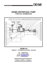
DESMI centrifugal pump MODULAR H DESMI A/S
DESMI centrifugal pump MODULAR H DESMI A/S
DESMI centrifugal pump MODULAR H DESMI A/S

You also want an ePaper? Increase the reach of your titles
YUMPU automatically turns print PDFs into web optimized ePapers that Google loves.
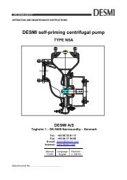
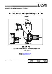
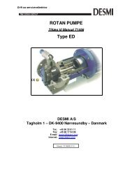
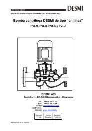
OPERATION AND MAINTENANCE INSTRUCTIONS<br />
<strong>DESMI</strong> <strong>centrifugal</strong> <strong>pump</strong><br />
<strong>MODULAR</strong> H<br />
<strong>DESMI</strong> A/S<br />
Tagholm 1 – DK-9400 Nørresundby – Denmark<br />
Tel.: +45 96 32 81 11<br />
Fax: +45 98 17 54 99<br />
E-mail: desmi@desmi.com<br />
Internet: www.desmi.com<br />
Special <strong>pump</strong> No..................................................<br />
Manual:<br />
T1340<br />
Language:<br />
English<br />
Revision:<br />
E (06/10)
TABLE OF CONTENTS: PAGE<br />
1. PRODUCT DESCRIPTION ........................................................................................................ 3<br />
1.1 DELIVERY ............................................................................................................................ 3<br />
2. TECHNICAL DATA .................................................................................................................... 3<br />
2.1 EXPLANATION OF THE TYPE NUMBER ............................................................................. 3<br />
2.2 TECHNICAL DESCRIPTION ................................................................................................. 4<br />
3. INSTALLATION .......................................................................................................................... 5<br />
3.1 MOUNTING/FASTENING ..................................................................................................... 5<br />
3.2 WIRING................................................................................................................................. 6<br />
4. TRANSPORT/STORAGE ........................................................................................................... 6<br />
5. DISMANTLING .......................................................................................................................... 7<br />
5.1 ACCESS TO IMPELLER AND SHAFT SEAL ........................................................................ 7<br />
5.2 DISMANTLING SHAFT SEAL ............................................................................................... 7<br />
5.3 DISMANTLING SEAT ........................................................................................................... 7<br />
5.4 DISMANTLING SHAFT WITH BEARINGS ............................................................................ 7<br />
5.5 INSPECTION ........................................................................................................................ 7<br />
6. ASSEMBLING ............................................................................................................................ 8<br />
6.1 FITTING SEALING RING IN PUMP CASING ........................................................................ 8<br />
6.2 FITTING SHAFT WITH BEARINGS ...................................................................................... 8<br />
6.3 FITTING WATER DEFLECTOR ............................................................................................ 8<br />
6.4 FITTING SHAFT SEAL ......................................................................................................... 8<br />
6.5 FITTING IMPELLER.............................................................................................................. 8<br />
6.6 FITTING BEARING HOUSING AND SHAFT SEAL COVER ................................................. 8<br />
6.7 SHAFT .................................................................................................................................. 9<br />
7. FROST PROTECTION .............................................................................................................. 9<br />
8. DISMANTLING .......................................................................................................................... 9<br />
9. START-UP ................................................................................................................................. 9<br />
9.1 STARTING ............................................................................................................................ 9<br />
10. SYSTEM BALANCING ........................................................................................................... 10<br />
11. INSPECTION AND MAINTENANCE ...................................................................................... 11<br />
11.1 DRAINING THE PUMP ..................................................................................................... 11<br />
11.2 BEARINGS ....................................................................................................................... 12<br />
12. REPAIRS ............................................................................................................................... 12<br />
12.1 ORDERING SPARE PARTS ............................................................................................. 12<br />
13. OPERATING DATA ................................................................................................................ 12<br />
14. EU DECLARATION OF CONFORMITY ................................................................................. 14<br />
15. ASSEMBLY DRAWING ......................................................................................................... 15<br />
16. SPARE PARTS LIST .............................................................................................................. 15<br />
17. DIMENSIONAL SKETCH ....................................................................................................... 16
1. PRODUCT DESCRIPTION<br />
These operation and maintenance instructions apply to the <strong>DESMI</strong> <strong>MODULAR</strong> H <strong>pump</strong><br />
series. The <strong>pump</strong>s are available in sizes ranging from 40 to 80 mm on the pressure flange.<br />
The suction flange is bigger than the pressure flange.<br />
<strong>DESMI</strong> H is a single-stage <strong>centrifugal</strong> <strong>pump</strong> with stainless steel shaft, mechanical shaft<br />
seal, and closed impeller.<br />
The <strong>pump</strong> is suitable for the <strong>pump</strong>ing of clean and polluted liquids with temperatures<br />
between 0 and 80°C. With special shaft seal up to 140°C. Max. number of revolutions:<br />
3600 RPM.<br />
The <strong>pump</strong> has horizontal inlet on the centre line and vertical outlet at the top.<br />
The back of the impeller is equipped with relief blades to reduce the load on the bearings.<br />
Relief holes in the impeller ensure circulation of liquid for the shaft seal and prevent<br />
overheating of the shaft seal during normal operation.<br />
The <strong>pump</strong> is particularly suitable for the <strong>pump</strong>ing of water in connection with washing<br />
plants, air conditioning, cooling systems, and sanitary systems, etc. Furthermore, in the<br />
majority of cases where transport of liquid is required within industry.<br />
1.1 DELIVERY<br />
- Check on delivery that the shipment is complete and undamaged.<br />
- Defects and damages, if any, to be reported to the carrier and the supplier<br />
immediately in order that a claim can be advanced.<br />
2. TECHNICAL DATA<br />
The <strong>pump</strong>s are manufactured in various material combinations which appear from the type<br />
number on the name plate. See below.<br />
2.1 EXPLANATION OF THE TYPE NUMBER<br />
All the H <strong>pump</strong>s are provided with a name plate. The type number indicated on the name<br />
plate is built up as follows:<br />
H-XX-YYY-MR<br />
XX,YYY: Pump size.<br />
M: The material combination of the <strong>pump</strong>.<br />
R: The assembly combination of the <strong>pump</strong>.<br />
M may be the following:<br />
A: Standard. Casing: GG20. Impeller:AlBz.<br />
<strong>DESMI</strong> A/S<br />
Tagholm 1<br />
9400 Nørresundby - Denmark<br />
Tel.: +45 96 32 81 11<br />
Fax +45 98 17 54 99<br />
E-mail: desmi@desmi.com<br />
www.desmi.com 3
C: All cast iron.<br />
D: Casing: BSP5, Impeller: AlBz.<br />
E: Special alloy.<br />
The <strong>pump</strong>s can be delivered in other material combinations which are agreed with the<br />
supplier.<br />
R may be the following:<br />
02: Monobloc, flange-mounted with electric motor.<br />
07: On base plate with petrol or diesel engine, or with electric motor.<br />
09: With bare shaft end.<br />
10: Special-tailored according to task.<br />
Any use of the <strong>pump</strong> is to be evaluated on the basis of the materials used in the <strong>pump</strong>. In<br />
case of doubt, contact the supplier.<br />
The <strong>pump</strong> is particularly suitable for the <strong>pump</strong>ing of water for cooling of diesel engines and<br />
cooling units, as bilge <strong>pump</strong>, ballast <strong>pump</strong>, fire <strong>pump</strong>, for irrigation, fish farms, water<br />
works, water lowering and much more.<br />
Pumps in material combinations A and C are primarily used for fresh water.<br />
Pumps in material combination D are primarily used for sea water.<br />
If the <strong>pump</strong>s are designed for special purposes the following is to be indicated:<br />
Pump No. : _______________________________________________________<br />
Pump type : _______________________________________________________<br />
Application: _______________________________________________________ :<br />
Comment : _______________________________________________________<br />
2.2 TECHNICAL DESCRIPTION<br />
The noise level indicated is the airborne noise including the motor. The noise depends on<br />
the motor type supplied, as the noise from the <strong>pump</strong> can be calculated as the noise level<br />
of the motor + 2dB(A). The noise levels indicated are for <strong>pump</strong>s with MEZ-motors.<br />
The capacity of the <strong>pump</strong> appears from the name plate on the <strong>pump</strong>. If the <strong>pump</strong> has been<br />
delivered without motor the <strong>pump</strong> capacity is to be indicated on the plate when mounting<br />
the motor.<br />
The permissible loads on the flanges appear from the following table:<br />
<strong>DESMI</strong> A/S<br />
Tagholm 1<br />
9400 Nørresundby - Denmark<br />
Tel.: +45 96 32 81 11<br />
Fax +45 98 17 54 99<br />
E-mail: desmi@desmi.com<br />
www.desmi.com 4
Pump Ø<br />
Pressure<br />
branch<br />
Fv<br />
N<br />
Fh<br />
N<br />
<strong>DESMI</strong> A/S<br />
Tagholm 1<br />
9400 Nørresundby - Denmark<br />
Tel.: +45 96 32 81 11<br />
Fax +45 98 17 54 99<br />
E-mail: desmi@desmi.com<br />
www.desmi.com 5<br />
Σ F<br />
N<br />
Σ Mt<br />
Nm<br />
H-40-160 40 1350 1000 �� �� ���<br />
H-50-160 50 1350 1000 �� �� ���<br />
H-50-200 50 1350 1000 �� �� � ��<br />
H-65-160 65 1450 1050 �� �� ���<br />
H-65-200 65 1450 1050 �� �� ���<br />
H-80-200 80 1800 1250 ���� ���<br />
In connection with the permissible loads on the flanges the following is to be observed:<br />
v F<br />
2<br />
Fzout + Fzin<br />
≤<br />
3<br />
h<br />
F<br />
2<br />
F xin<br />
+<br />
2<br />
F yin<br />
+<br />
2<br />
F xout +<br />
2<br />
F yout ≤<br />
2<br />
M xin<br />
+<br />
2<br />
M yin<br />
+<br />
2<br />
M zin<br />
+<br />
2<br />
M xout +<br />
2<br />
M yout +<br />
2<br />
M Zout<br />
≤<br />
⎛ ∑ F calc<br />
⎜<br />
⎝ ∑ F<br />
2<br />
2<br />
⎞ ⎛ ∑ M calc ⎞<br />
⎟ + ⎜ ⎟ � 2<br />
⎟ ⎜ ⎟<br />
⎠ ⎝ ∑ Mt<br />
⎠<br />
where indices "in" is suction branch, "out" is pressure branch, and "calc" are the values<br />
calculated by the user.<br />
3. INSTALLATION<br />
3.1 MOUNTING/FASTENING<br />
The <strong>pump</strong> should be mounted and fastened on a solid base plate with a flat and horizontal<br />
surface to avoid distortion.<br />
The max. permissible loads on the flanges stated in paragraph 2.2 are to be observed.<br />
When mounting a V-belt pulley on the <strong>pump</strong> a bore H7 is recommended. To facilitate the<br />
mounting the hub in the V-belt pulley may be heated to abt. 100°C after which the V-belt<br />
pulley is easily lead over the shaft towards the shoulder. Alternatively, a V-belt pulley may<br />
be mounted with a TAPER LOCK bush.<br />
When dimensioning the V-belt pulley it is important to follow the rules of the <strong>DESMI</strong><br />
nomograms for the <strong>pump</strong> size in question - contact <strong>DESMI</strong>.<br />
t M
If the <strong>pump</strong> is to be driven by a motor via a flexible coupling, motor and <strong>pump</strong> are to be<br />
placed on a common base plate. The following should be observed:<br />
- Avoid distortion of the base plate.<br />
- Avoid distortion in the piping system.<br />
- Check that <strong>pump</strong> and motor are aligned correctly.<br />
3.2 WIRING<br />
When connecting the <strong>pump</strong> and a prime mover the power transmission is to be<br />
equipped with a guard in accordance with the provisions of the COUNCIL<br />
DIRECTIVE of June 14, 1989, on the safety of machines.<br />
At installations <strong>pump</strong>ing hot or very cold liquids, the operator must be aware<br />
that it is dangerous to touch the <strong>pump</strong> surface, and, consequently, he must<br />
take the necessary safety measures.<br />
Wiring to be carried out by authorized skilled workmen according to the rules<br />
and regulations in force.<br />
4. TRANSPORT/STORAGE<br />
The weights of the <strong>pump</strong>s (in A09 combination) are indicated in the following table, and the<br />
<strong>pump</strong>s are to be lifted as shown.<br />
Pump Weight kg<br />
H-40-160 28.5<br />
H-50-160 30.0<br />
H-65-160 36.0<br />
H-50-200 35.0<br />
H-65-200 41.0<br />
H-80-200 61.5<br />
The <strong>pump</strong> is to be stored in a dry area.<br />
Before shipment the <strong>pump</strong> is to be fastened securely on pallets or the like.<br />
<strong>DESMI</strong> A/S<br />
Tagholm 1<br />
9400 Nørresundby - Denmark<br />
Tel.: +45 96 32 81 11<br />
Fax +45 98 17 54 99<br />
E-mail: desmi@desmi.com<br />
www.desmi.com 6
The <strong>pump</strong> is to be lifted as shown here:<br />
The lifting straps must not bear against sharp edges and corners.<br />
5. DISMANTLING<br />
5.1 ACCESS TO IMPELLER AND SHAFT SEAL<br />
Remove Allen screws (22), which hold the shaft seal cover to the <strong>pump</strong> casing, and pull<br />
the bearing housing to remove the complete bearing housing with impeller, bearings, and<br />
shaft.<br />
5.2 DISMANTLING SHAFT SEAL<br />
Remove nut (6). Pull off the impeller. Remove Allen screws (19), which hold the bearing<br />
housing to the shaft seal cover, pull shaft seal cover and bearing housing apart, by which<br />
shaft seal and water deflector are pulled off the shaft.<br />
5.3 DISMANTLING SEAT<br />
Press out the seat from behind the shaft seal cover.<br />
5.4 DISMANTLING SHAFT WITH BEARINGS<br />
Before dismantling the shaft with bearings, remove the sunk key (16). The shaft can now<br />
be pulled out of the bearing housing allowing inspection of the bearings.<br />
5.5 INSPECTION<br />
When the <strong>pump</strong> has been dismantled, check the following parts for wear and damage:<br />
- Sealing ring/impeller: Max. clearance 0.4-0.5 mm measured in radius.<br />
- Shaft seal/shaft seal cover: Check the seat for flatness and cracks.<br />
Check the rubber parts for elasticity.<br />
- Bearings: Replace in case of wear and noise.<br />
<strong>DESMI</strong> A/S<br />
Tagholm 1<br />
9400 Nørresundby - Denmark<br />
Tel.: +45 96 32 81 11<br />
Fax +45 98 17 54 99<br />
E-mail: desmi@desmi.com<br />
www.desmi.com 7
6. ASSEMBLING<br />
6.1 FITTING SEALING RING IN PUMP CASING<br />
When fitted, the sealing ring is to bear against the shoulder of the <strong>pump</strong> casing.<br />
6.2 FITTING SHAFT WITH BEARINGS<br />
Lead shaft with bearings into the bearing housing. Fit sunk key (16).<br />
6.3 FITTING WATER DEFLECTOR<br />
Assemble the bearing housing and the shaft seal cover. Lead the water deflector over the<br />
shaft until it touches the shaft seal cover and then further 1-1.5 mm into the shaft seal<br />
cover.<br />
6.4 FITTING SHAFT SEAL<br />
Before fitting the seat, clean the recess in the shaft seal cover. When fitting the seat,<br />
remove<br />
the protective coating without scratching the lapped surface. Dip the outer rubber ring of<br />
the seat into<br />
olive oil (or another neutral oil). Now press the seat into place with the fingers and check<br />
that all parts are correctly imbedded. If it is necessary to use tools for assembling, then<br />
protect the sliding surface of the seat to prevent it from being scratched or cut. Lubricate<br />
the inner diameter of the slide ring rubber bellows with olive oil and push it over the shaft.<br />
The use of a fitting bush as shown on the assembly drawing is recommended to avoid that<br />
the rubber bellows is cut. Push the slide ring over the shaft with the hand. If the rubber<br />
bellows is tight, use a fitting tool and take care that the slide ring is not damaged.<br />
If the carbon ring is not fixed, it is important to check that it is fitted correctly, i.e. the<br />
chamfered/lapped side is to face the seat. The carbon ring can be held by a little grease.<br />
When using oil on the shaft, the bellows will settle and seat in about 15 minutes, and until<br />
then tightness should not be expected. After start, check by viewing the leak hole that<br />
there are no leaks.<br />
6.5 FITTING IMPELLER<br />
Fit the sunk key in the shaft and lead the impeller towards the shoulder of the shaft. Take<br />
care that the ring at the end of the shaft seal spring locates in the recess of the impeller.<br />
Secure the impeller with a washer and a nut.<br />
6.6 FITTING BEARING HOUSING AND SHAFT SEAL COVER<br />
Place the gasket between <strong>pump</strong> casing and shaft seal cover on the shaft seal cover where<br />
it can be held with a little grease. Fit and fasten bearing housing with shaft seal cover.<br />
Check that the drain passage for the shaft seal faces downwards.<br />
<strong>DESMI</strong> A/S<br />
Tagholm 1<br />
9400 Nørresundby - Denmark<br />
Tel.: +45 96 32 81 11<br />
Fax +45 98 17 54 99<br />
E-mail: desmi@desmi.com<br />
www.desmi.com 8
6.7 SHAFT<br />
When the <strong>pump</strong> has been assembled, check that the shaft rotates freely.<br />
7. FROST PROTECTION<br />
Pumps which are not in operation during frost periods are to be drained to avoid frost<br />
damage. Remove the plug at the bottom to empty the <strong>pump</strong>. Alternatively, it is possible to<br />
use anti-freeze liquids in normal constructions.<br />
8. DISMANTLING<br />
9. START-UP<br />
Before dismantling the <strong>pump</strong> make sure that it has stopped. Empty the <strong>pump</strong><br />
of liquid before it is dismantled from the piping system. If the <strong>pump</strong> has been<br />
<strong>pump</strong>ing dangerous liquids you are to be aware of this and take the necessary<br />
safety measures.<br />
If the <strong>pump</strong> has been <strong>pump</strong>ing hot liquids, take great care that it is drained<br />
before it is removed from the piping system.<br />
A <strong>centrifugal</strong> <strong>pump</strong> will not function until it has been filled with liquid between<br />
the foot valve and somewhat above the impeller of the <strong>pump</strong>.<br />
The liquid also serves as coolant for the shaft seal. In order to protect the shaft seal the<br />
<strong>pump</strong> must not run dry.<br />
ATTENTION<br />
For safety reasons the <strong>pump</strong> is only allowed to operate against closed suction and<br />
discharge valves for a short time (max. 5-10 minutes and at a max. temperature of 130°C).<br />
Otherwise there is a risk of damage to the <strong>pump</strong> and, at worst, of a steam explosion. If the<br />
<strong>pump</strong> room is unmanned, the installation of a safety device is recommended.<br />
9.1 STARTING<br />
Before starting the <strong>pump</strong> check that:<br />
- the shaft rotates freely without jarring sounds.<br />
- the <strong>pump</strong> casing and the suction line are filled with liquid.<br />
Start the <strong>pump</strong> for a moment to check the direction of rotation. If the direction is correct<br />
(i.e. in the direction of the arrow) the <strong>pump</strong> may be started.<br />
<strong>DESMI</strong> A/S<br />
Tagholm 1<br />
9400 Nørresundby - Denmark<br />
Tel.: +45 96 32 81 11<br />
Fax +45 98 17 54 99<br />
E-mail: desmi@desmi.com<br />
www.desmi.com 9
10. SYSTEM BALANCING<br />
It is often difficult to calculate a manometric delivery head in advance. It is, however,<br />
decisively important to the quantity of liquid delivered.<br />
A considerably smaller delivery head than expected will increase the quantity of liquid<br />
delivered, causing increased power consumption and perhaps cavitation in <strong>pump</strong> and<br />
piping. In the <strong>pump</strong> the impeller may show signs of heavy erosion caused by cavitation<br />
(corrosion) which may at times render an impeller unfit for use in a very short time. Not<br />
unusually do similar erosions occur in pipe bends and valves elsewhere in the piping<br />
system.<br />
Therefore, after start-up, it is necessary to check either the quantity of liquid delivered or<br />
the power consumption of the <strong>pump</strong> e.g. by measuring the current intensity of the<br />
connected motor.<br />
Together with a reading of the differential pressure the quantity of water delivered can be<br />
determined against the characteristics of the <strong>pump</strong>.<br />
Should the <strong>pump</strong> not function as intended, please proceed according to the fault-finding<br />
list. Bear in mind, though, that the <strong>pump</strong> was carefully checked and tested at the factory<br />
and that the majority of faults stem from the piping system.<br />
<strong>DESMI</strong> A/S<br />
Tagholm 1<br />
9400 Nørresundby - Denmark<br />
Tel.: +45 96 32 81 11<br />
Fax +45 98 17 54 99<br />
E-mail: desmi@desmi.com<br />
www.desmi.com 10
FAULT CAUSE REMEDY<br />
The <strong>pump</strong> has no or<br />
too low capacity<br />
The <strong>pump</strong> uses too<br />
much power<br />
The <strong>pump</strong> makes<br />
noise<br />
1. Wrong direction of<br />
rotation<br />
2. Piping system choked<br />
3. The <strong>pump</strong> is choked<br />
4. Suction line leaks<br />
<strong>pump</strong> takes air<br />
5. Suction lift too high<br />
6. Pump and piping system<br />
wrongly dimensioned<br />
1. Counter-pressure too<br />
low<br />
2. The liquid is heavier<br />
than water<br />
3. Foreign body in <strong>pump</strong><br />
4. Electric motor is<br />
running on 2 phases<br />
11. INSPECTION AND MAINTENANCE<br />
Inspect the shaft seal for leaks at regular intervals.<br />
<strong>DESMI</strong> A/S<br />
Tagholm 1<br />
9400 Nørresundby - Denmark<br />
Tel.: +45 96 32 81 11<br />
Fax +45 98 17 54 99<br />
E-mail: desmi@desmi.com<br />
www.desmi.com 11<br />
Change direction of<br />
rotation to clockwise<br />
when viewed from<br />
shaft end (the<br />
direction of the arrow)<br />
Clean or replace<br />
Clean the <strong>pump</strong><br />
Find the leakage,<br />
repair<br />
the fault, non-return<br />
valve not submerged<br />
Check data sheet<br />
Q/H<br />
curve and NPSH or<br />
contact <strong>DESMI</strong><br />
As 5<br />
Insert orifice plate or<br />
check valve/Contact<br />
<strong>DESMI</strong><br />
Contact <strong>DESMI</strong><br />
Dismantle the <strong>pump</strong>,<br />
remove the cause<br />
Check fuses, cable<br />
Connection, and<br />
cable<br />
1. Cavitation in <strong>pump</strong> Suction lift too high/<br />
Suction line wrongly<br />
Dimensioned/Liquid<br />
Temperature too high<br />
- Before inspection of a <strong>pump</strong> without guard check that the <strong>pump</strong> cannot be started<br />
unintentionally.<br />
- The system is to be without pressure.<br />
- The repairman must be familiar with the type of liquid which has been <strong>pump</strong>ed as<br />
well as the safety measures he is to take when handling the liquid.<br />
11.1 DRAINING THE PUMP<br />
When the piping system has been drained, note that there is still liquid in the <strong>pump</strong>.
Remove the liquid by dismantling the pipe plug (75) at the bottom of the <strong>pump</strong>.<br />
11.2 BEARINGS<br />
The <strong>pump</strong> is equipped with ball bearings with a nominal life of 25,000 working hours when<br />
direct coupled to electric motor, whereas the nominal life with overhanging V-belt drive is<br />
about 10,000 working hours. The bearings are lubricated for life and require no attention<br />
but are to be replaced in case of noise or bearing wear.<br />
12. REPAIRS<br />
12.1 ORDERING SPARE PARTS<br />
When ordering spare parts please always state <strong>pump</strong> type and serial No. (appears from<br />
the name plate of the <strong>pump</strong>). See also spare parts drawing with item Nos.<br />
13. OPERATING DATA<br />
The following working pressures are allowed:<br />
PUMP H-40-160 H-50-160 H-65-160 H-50-200 H-65-200 H-80-200<br />
PRESSURE<br />
mWC 80 80 80 110 110 110<br />
The above-mentioned max. working pressure is NOT valid for <strong>pump</strong>s approved by a<br />
classification society. Pumps approved by classification societies have been pressure<br />
tested according to the requirements of these societies, i.e. a test pressure of 1.5 x the<br />
permissible working pressure. The test pressure is stated in the test certificate and<br />
stamped into the discharge flange of the <strong>pump</strong>.<br />
The powers stated in the table below are the highest possible absorbed by the <strong>pump</strong>,<br />
whereas the min./max. values for flow and pressure indicate <strong>DESMI</strong>'s recommended<br />
operating range for the <strong>pump</strong>.<br />
<strong>DESMI</strong> A/S<br />
Tagholm 1<br />
9400 Nørresundby - Denmark<br />
Tel.: +45 96 32 81 11<br />
Fax +45 98 17 54 99<br />
E-mail: desmi@desmi.com<br />
www.desmi.com 12
Impeller<br />
diameter Ø<br />
Max. power<br />
kw<br />
1450/1750/-<br />
2950/3500 RPM<br />
Min. Power<br />
m3/h<br />
1450/1750/-<br />
2950/3500 RPM<br />
<strong>DESMI</strong> A/S<br />
Tagholm 1<br />
9400 Nørresundby - Denmark<br />
Tel.: +45 96 32 81 11<br />
Fax +45 98 17 54 99<br />
E-mail: desmi@desmi.com<br />
www.desmi.com 13<br />
Max. Flow<br />
m3/h<br />
1450/750/-<br />
2950/3500 RPM<br />
Min. Pressure<br />
mWC<br />
1450/1750/-<br />
2950/3500 RPM<br />
Max. Pressure<br />
mWC<br />
1450/1750/-<br />
2950/3500 RPM<br />
H-40-160 Ø175 0.8/1.3/5.7/9.4 8.0/11.0/18.0/22 26/30/50/68 4.0/7.0/20/28 9.0/13.0/37/53<br />
H-40-160 Ø165 0.6/1.1/4.8/8 7.0/8.0./15.0/19 25/30/45/57 3.5/5.5/17.0./23 8.4/12.0/34/47<br />
H-40-160 Ø 155 0.5/0.9/4.0/6.5 6.0/7.0/12.5/15 23/28/43/55 3.0/4.7/13.0/18 7.3/10.7/30/42<br />
H-50-160 Ø175 1.0/1.7/8.0/13.0 18.0/20/35/36 41/49/83/98 6.0/9.0/24/98 9.2/13.6/38/54<br />
H-50-160 Ø165 0.9/1.5/6.8/11.2 15.0/18.0/27/32 38/47/79/95 5.5/8.2/22/95 8.4/12.4/35/49<br />
H-50-160 Ø175 0.7/1.3/5.8/9.5 14.0/17.0/26/31 37/45/75/88 4.9/7.2/20/90 7.7/11.1/32/44<br />
H-65-160 Ø175 1.8/3.0/13.2/22 36/44/73/80 78/93/157/184 5.2/7.6/21/30 8.6/12.5/35/50<br />
H-65-160 Ø165 1.5/2.5/11.0/18.0 32/40/60/70 75/85/151/170 3.0/6.0/16.0/25 7.2/11.0/32/44<br />
H-65-160 Ø155 1.3/2.1/8.8/15.0 25/32/50/60 70/78/141/165 1.5/4.5/9.0/15.0 6.2/9.2/27/38<br />
H-50-200 Ø220 2.5/4.2/18.5/31 23/25/40/47 53/62/95/114 9.5/15.0/46/63 15.2/22/63/88<br />
H-50-200 Ø205 2.1/3.5/15.5/26 20/22/35/40 50/58/90/108 9.0/13.5/42/57 14.0/20/57/80<br />
H-50-200 Ø190 1.8/3.0/13.2/22 17.0/18.0/30/33 47/55/85/103 7.8/12.0/35/51 12.6/18/51/72<br />
H-65-200 Ø220 3.3/5.8/27/44 37/45/76/86 90/105/182/200 9.0/14.0/37/57 15.0/22/61/86<br />
H-65-200 Ø205 2.7/4.7/22/36 32/38/63/72 85/95/170/186 8.0/12.5/32/49 13.2/19.0/53/75<br />
H-65-200 Ø190 2.2/3.7/17.5/29 23/27/46/52 77/90/157/172 7.0/10.5/28/42 11.6/16.8/47/66<br />
H-80-200 Ø220 4.8/8.2/38/63 56/72/112/115 140/168/270/330 8.2/12.0/33/41 14.7/21/61/85<br />
H-80-200 Ø205 3.9/6.7/31/51 50/60/95/105 130/156/260/300 7.1/10.4/27/38 12.7/18.5/53/73<br />
H-80-200 Ø190 3.1/5.3/24/40 40/43/88/95 120/145/245/280 6.2/9.0/23/31 11.2/16.2/46/64
14. EU DECLARATION OF CONFORMITY<br />
<strong>DESMI</strong> A/S, hereby declare that our <strong>pump</strong>s of the Modular H type are manufactured in<br />
conformity with the following essential safety and health requirements in the COUNCIL<br />
DIRECTIVE 2006/42/EC on machines, Annex 1.<br />
The following harmonized standards have been used:<br />
EN 294:1994 Safety of machinery. Safety distances to prevent danger zones<br />
being reached by the upper limbs<br />
EN 809 + A1 Pumps and <strong>pump</strong> units for liquids – Common safety<br />
requirements<br />
EN 12162:2001 Liquid <strong>pump</strong>s – Safety requirements – Procedure for hydrostatic<br />
testing<br />
EN 60204- Safety of machinery – Electrical equipment of machines (item 4,<br />
1:2006<br />
General requirements)<br />
Pumps delivered by us connected with prime movers are CE-marked and comply with the<br />
above requirements.<br />
Pumps delivered by us without prime movers (as partly completed machinery) must only<br />
be used when the prime mover and the connection between prime mover and <strong>pump</strong><br />
comply with the above requirements.<br />
Nørresundby, June 1, 2010<br />
Kurt Bech Christensen<br />
Technical Director<br />
<strong>DESMI</strong> A/S<br />
Tagholm 1<br />
9400 Nørresundby<br />
<strong>DESMI</strong> A/S<br />
Tagholm 1<br />
9400 Nørresundby - Denmark<br />
Tel.: +45 96 32 81 11<br />
Fax +45 98 17 54 99<br />
E-mail: desmi@desmi.com<br />
www.desmi.com 14
15. ASSEMBLY DRAWING<br />
16. SPARE PARTS LIST<br />
1 Pump casing 15 Ball bearing<br />
2 Pipe plug 16 Sunk key<br />
3 Pipe plug 17 Shaft<br />
4 Sealing ring 18 Bearing housing<br />
5 Impeller 19 Allen screw<br />
6 Nut 20 Shaft seal cover<br />
7 Spring collar 21 Gasket<br />
8 Washer 22 Allen screw<br />
9 Sunk key 27 Pipe plug<br />
10 Mechanical shaft seal 80 Sealing washer<br />
11 Water deflector 81 Sealing washer<br />
12 Ring lock 82 Sealing washer<br />
13 Ball bearing<br />
14 Support disc<br />
<strong>DESMI</strong> A/S<br />
Tagholm 1<br />
9400 Nørresundby - Denmark<br />
Tel.: +45 96 32 81 11<br />
Fax +45 98 17 54 99<br />
E-mail: desmi@desmi.com<br />
www.desmi.com 15
17. DIMENSIONAL SKETCH<br />
Type a f l g h2 h1 d t u s m2 m1 C b n2<br />
H-40-160 80 292 50 125 160 132 24j6 27 8 14 70 100 12 50 190<br />
H-50-160 100 292 50 145 180 160 24j6 27 8 14 70 100 12 50 212<br />
H-65-160 100 292 50 171 200 160 24j6 27 8 14 95 125 12 65 212<br />
H-50-200 100 292 50 160 200 160 24j6 27 8 14 70 100 12 50 212<br />
H-65-200 100 292 50 185 225 180 24j6 27 8 14 95 125 12 65 250<br />
H-80-200 125 385 80 192 250 180 32j6 35 10 14 95 125 14 65 280<br />
Type nl D1 K1 Dn1 Y1 D2 K2 Dn2 Y2 Q R<br />
H-40-<br />
160<br />
240 185 145 65 4xø18 150 110 40 4xø18 ¼” BSP 3/8”BSP<br />
H-50-<br />
160<br />
265 185 145 65 4xø18 165 125 50 4xø18 ¼” BSP 3/8”BSP<br />
H-65-<br />
160<br />
280 200 160 80 8xø18 185 145 65 4xø18 3/8” BSP 3/8”BSP<br />
H-50-<br />
200<br />
265 185 145 65 4xø18 165 125 50 4xø18 3/8” BSP 3/8”BSP<br />
H-65-<br />
200<br />
320 200 160 80 8xø18 185 145 65 4xø18 3/8” BSP 3/8”BSP<br />
H-80-<br />
200<br />
345 220 180 100 8xø18 200 160 80 8xø18 3/8” BSP 3/8”BSP<br />
<strong>DESMI</strong> A/S<br />
Tagholm 1<br />
9400 Nørresundby - Denmark<br />
Tel.: +45 96 32 81 11<br />
Fax +45 98 17 54 99<br />
E-mail: desmi@desmi.com<br />
www.desmi.com 16
<strong>DESMI</strong> A/S<br />
Tagholm 1<br />
9400 Nørresundby - Denmark<br />
Tel.: +45 96 32 81 11<br />
Fax +45 98 17 54 99<br />
E-mail: desmi@desmi.com<br />
www.desmi.com 17