marine transmission owners manual - TransDiesel
marine transmission owners manual - TransDiesel
marine transmission owners manual - TransDiesel

Create successful ePaper yourself
Turn your PDF publications into a flip-book with our unique Google optimized e-Paper software.
MARINE TRANSMISSION<br />
OWNERS MANUAL<br />
TONAN CORPORATION<br />
992 SHISHIKO USHIKU IBARAKI 300-1231 JAPAN
My <strong>transmission</strong> details<br />
(Record the details for your <strong>transmission</strong> here for quick reference)<br />
Vessel Name:<br />
Transmission Model:<br />
TM<br />
Serial Number:<br />
Ratio: :1<br />
Date of purchase: / /<br />
Day / Month / Year<br />
Purchased from:<br />
2
Table of Contents<br />
Warranty ................................................................................ 4<br />
General Information .............................................................. 5<br />
Description ............................................................................ 6<br />
Construction Features ............................................................ 8<br />
Installation ............................................................................. 9<br />
Operation ............................................................................. 15<br />
Emergency Mechanical Lock-up ......................................... 16<br />
Oil & Lubrication ................................................................ 22<br />
Preventative Maintenance .................................................... 24<br />
Trouble shooting .................................................................. 26<br />
Replacement Parts Ordering ................................................ 28<br />
Dealers and distributors ....................................................... 29<br />
3
SECTION 1<br />
Warranty<br />
Tonan Corporation (hereafter referred to as the „The Transmission Manufacturer) guarantees all assembled<br />
products and parts, (except component products or parts on which written warranties issued by the respective<br />
manufacturers thereof are furnished to the original purchaser, as to which the Transmission Manufacturer<br />
assumes no liability) against defective materials, or workmanship for a period of twenty-four(24) months<br />
from the date of original shipment, but not to exceed twelve (l2) months or two thousand (2,000) hours<br />
of service, whichever occurs first. The original purchaser does not rely upon any tests or inspections to such<br />
products or parts by the <strong>transmission</strong> manufacturer.<br />
No other warranties expressed or implied are intended or given.<br />
The exclusive remedy provided within the applicable warranty period specified in paragraph above shall be, at<br />
the sole option of the Transmission Manufacturer, either the repair or replacement of any part or product found<br />
to be defective and the labour to perform the repair or replacement (or equivalent credit). Labour is defined as<br />
the flat rate labour hours required to disassemble, inspect and reassemble the product only as published in the<br />
flat rate <strong>manual</strong>. The above is subject to the following terms and conditions:<br />
‣ Complete parts or products must be returned to the Transmission Manufacturer within the warranty<br />
period, transportation charges prepaid.<br />
‣ This warranty is void if, in the opinion of the Transmission Manufacturer, the failure of the returned<br />
part or product resulted from abuse or neglect or where such failure has been caused by accident.<br />
‣ Labour or other costs or expenses incurred by the buyer for removal and reinstallation of the part or<br />
product is not covered by this warranty and the buyer assumes full responsibility for such costs and<br />
charges.<br />
‣ The warranty is void unless the buyer or his agents provide proper transportation and storage facilities<br />
and reasonable care of the complete product or part from the date of shipment to the date placed in<br />
service.<br />
‣ This warranty is void unless the buyer causes the product or part to be properly installed within the<br />
rated capacity of the product or part with installations properly engineered and in accordance with the<br />
practices, methods and instructions approved by the Transmission Manufacturer.<br />
‣ This warranty is valid only if all required replacement parts or products are equal, and otherwise<br />
identical with components of the original equipment.<br />
‣ The warranty is void if any modifications are made to any product or part without the prior written<br />
consent of the Transmission Manufacturer.<br />
In consideration for this warranty buyer agrees to indemnify and hold seller harmless from and against all and<br />
any loss, liability, damages or expenses for injury to persons or property, including, without limitation, buyer's<br />
employees and property due to the acts or omissions of the buyer, its agents, and employees in the installation,<br />
use and operation of said equipment and shall assert no claim against seller for consequential damages.<br />
Only authorized factory representatives shall have authority to assume any cost or expense in the service,<br />
repair or replacement of any part or product within the warranty period except when such cost or expense is<br />
authorized in advance in writing.<br />
The Transmission Manufacturer reserves the right to improve the product through changes in design or<br />
material without being obligated to incorporate such changes in products of prior manufacture. Buyer will not<br />
rely on any such changes as proof of insufficiency or inadequacy of prior designs of material.<br />
4
SECTION 2<br />
General Information<br />
A. Scope<br />
This owner‟s <strong>manual</strong> contains instructions for the operation, and installation of the Tonanco <strong>marine</strong><br />
<strong>transmission</strong>. This <strong>manual</strong> should be made available to, and read in its entirety by all personnel<br />
responsible for the operation and maintenance of the unit. A thorough understanding and application<br />
of the material in this <strong>manual</strong> will assist in obtaining long and satisfactory service from the <strong>marine</strong><br />
<strong>transmission</strong>.<br />
B. Safety<br />
All persons operating or involved with this equipment should employ safe working practices and<br />
abide by the current workplaces laws of their county and those of any country that they may be<br />
working in.<br />
All personnel should be conversant with all aspects and appropriately trained in the use,<br />
maintenance, repair procedures and all other facets of the safe operation of the <strong>transmission</strong> unit.<br />
Tonan Corporation or any of its representatives will not be responsible for any injuries, losses or<br />
damages from improper use, carelessness or unsafe work practices.<br />
C. Installation<br />
It is recommended that the installation of this unit be carried out by a qualified or trained<br />
professionals. Many aspects of the installation can be hazardous and of a specialist nature. Many<br />
other considerations need to be taken into account when installing any component in a propulsion<br />
package.<br />
Local laws may differ from country to country so check with your local authorities before<br />
commencing installation as to the correct requirements to suit your application.<br />
D. Servicing<br />
Tonanco <strong>transmission</strong>s require regular maintenance and failure to carry out such servicing will<br />
reduce the life of the unit and may void any and all warranty claims.<br />
E. Parts Lists<br />
Exploded view illustrations with complete parts are provided in the SP series bulletins to facilitate<br />
ordering spare or replacement parts. Additional copies of these <strong>manual</strong>s are available from your local<br />
dealer.<br />
F. Trouble-shooting<br />
This <strong>manual</strong> also contains a trouble-shooting table, which will assist in determining the cause of<br />
functional difficulties, which may occur. Proper use of the symptom, cause and remedy columns of<br />
the tables will determine whether a simple repair can be accomplished on the <strong>marine</strong> <strong>transmission</strong> or<br />
whether complete disassembly and overhaul is necessary.<br />
5
SECTION 3<br />
Description<br />
Tonanco <strong>marine</strong> <strong>transmission</strong>s are multidirectional (forward and reverse) and combine a reduction<br />
unit. They are available in five base models (TM729 to TM1009) and in shallow case and deep case<br />
configurations.<br />
Many ratios are available in the range and can be loosely recognised by the case size. The shallow<br />
and deep case units are very similar. The two major differences between the shallow and deep case<br />
configuration are their main housing and bottom cover.<br />
A. Type<br />
1. This <strong>transmission</strong> is a close coupled flange type unit, bolted directly to the engine flywheel<br />
housing.<br />
2. The driving ring or flexible input coupling furnished with the <strong>transmission</strong> is installed on the<br />
engine flywheel. The outer ring is designed to mesh with internal the rubber blocks or<br />
elements on the input drive assembly of the input shaft. This method of drive is used because<br />
of the comparatively ease of removal and installation, however, care must be exercised<br />
during installation to ensure that proper alignment between the <strong>marine</strong> <strong>transmission</strong> and the<br />
engine is attained.<br />
3. This <strong>marine</strong> <strong>transmission</strong> is controlled completely hydraulically. The <strong>transmission</strong> contains<br />
hardened and ground helical tooth gears and pinions, which are in constant mesh. An oil<br />
pump supplies oil pressure to the selector valve assembly for clutch engagement. Both the<br />
forward and reverse clutches are operated by main pressure oil supply. The gears, bearings<br />
and clutches are lubricated and cooled with low-pressure oil.<br />
B. Oil Pump Drive<br />
The gear type oil pump assembly is spline-connected and driven by the reverse shaft.<br />
C. Changing Rotation<br />
1. The standard Tonanco <strong>marine</strong> <strong>transmission</strong> model as described in this <strong>manual</strong> is a righthand<br />
rotation unit (when viewed from the front of engine) for installation on a right-hand<br />
engine. The <strong>transmission</strong> can be converted easily and quickly for left-hand rotation<br />
applications by remounting the oil pump.<br />
2. To adapt to opposite engine rotation, remove the oil filter cover with oil suction hose<br />
attached. Remove the oil outlet hose. Remove oil pump, turn it 180 degrees and reinstall<br />
it. Install the suction hose where the outlet hose was and the outlet hose where the<br />
suction hose was. Remove the rotation indicator plate, turn it 180 degrees and re-install<br />
Replace ventilating cover to opposite engine rotation. This component is available from<br />
your local dealer.<br />
6
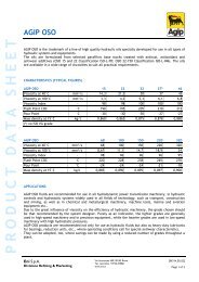
D. Direction of Drive<br />
The input shaft and driving reverse gear always rotate in engine direction. The reverse shaft<br />
and driven reverse gear always rotate in anti-engine direction because the driven reverse gear<br />
is meshed with the driving reverse gear on the input shaft. When the forward clutch is<br />
engaged, the input pinion rotates in engine direction. The output gear, which is fixed to the<br />
output shaft, is meshed with the input pinion and the output gear and shaft are driven in antiengine<br />
direction. When the reverse clutch is engaged, the reverse pinion rotates anti-engine<br />
direction. The output gear is meshed with the reverse pinion and, therefore, the output gear<br />
and shaft are driven in engine direction.<br />
Conventional engine direction of rotation<br />
Standard direction of rotation (output) when in forward<br />
7
SECTION 4<br />
Construction Features<br />
A. Housing<br />
The Tonanco housing is constructed of a cast iron one-piece main housing, a<br />
bottom cover, and is available in SAE#0, SAE #1 front housing on all larger<br />
models and the TM729 series SAE#1 and SAE#2 only.<br />
B. Input Drive Assembly<br />
1. Input drives are available two types: Rubber Block Drive (RBD) or a<br />
flexible torsional input (Centa R series). Both have a SAE nominal clutch<br />
diameter of 11 ½", 14" or 18" depending on model and housing selection.<br />
2. The RBD consists of a drive ring mounted to the fly wheel 26 rubber drive<br />
blocks and an input spider mounted to the <strong>transmission</strong>. A flexible torsional<br />
input also consists of a drive ring, a number of rubber elements and a drive<br />
also mounted to the input of the <strong>transmission</strong>.<br />
3. Both designs require the drive ring to be secured to the flywheel before<br />
assembly<br />
C. Front Housing<br />
Besides the upper ventilating opening, for increasing the ventilating-effects,<br />
the front housing is provided an air-intake port at the lower part of the<br />
housing. All Tonanco units are of a dry front housing configuration.<br />
D. Lubrication Features<br />
1. The oil return pipe assembly extending fore and aft, near the top of main<br />
housing, serves as an oil distribution medium. This pipe supplies low<br />
pressure oil through cross drilled holes in the front housing to the tapered<br />
roller bearings of both reverse gears. Cross-drilled holes in the pipe spray<br />
low-pressure oil on output gear and pinions.<br />
The tube carrier assembly is mounted on the oil return pipe. Lubricating oil<br />
is also directed from the pipe through smaller tubes to the other tapered roller<br />
bearing on the both clutch shafts and pinions.<br />
2. Besides the main oil strainer/filter, a cartridge type oil filter is mounted on<br />
the top cover of some models. This is to provide filtered oil for cooling and<br />
lubrication to the top gears<br />
8
SECTION 5<br />
Installation<br />
Prior to Installation<br />
CAUTION<br />
THE TRANSMISSION MOUNTS DIRECTLY ONTO THE FLYWHEEL OF THE ENGINE.<br />
FLYWHEEL-TO-DRIVEN-TRANSMISSION INTERFERENCE IS POSSIBLE DUE TO<br />
MISMATCH OF TRANSMISSION OR OTHER REASONS. THEREFORE, ENGINE<br />
CRANKSHAFT ENDPLAY AS WELL AS FLYWHEEL ALIGNMENT CHECKS MUST BE<br />
MADE BEFORE THE TRANSMISSION IS INSTALLED.<br />
AFTER INSTALLATION OF THE TRANSMISSION, CRANKSHAFT ENDPLAY SHOULD<br />
BE MEASURED AGAIN. ENDPLAY AT THE SECOND MEASUREMENT SHOULD BE<br />
THE SAME AS THE FIRST. ANY DIFFERENCE OF THESE TWO ENDPLAY<br />
MEASUREMENTS COULD BE AN INDICATION OF INTERFERENCE.<br />
CONSEQUENTLY, THE TRANSMISSION SHOULD BE REMOVED AND THE SOURCE<br />
OF INTERFERENCE FOUND AND CORRECTED.<br />
THE MANUFACTURER WILL NOT BE RESPONSIBLE FOR SYSTEM DAMAGE<br />
CAUSED BY ENGINE TO TRANSMISSION INTERFERENCE REGARDLESS OF THE<br />
CAUSE OF INTERFERENCE. THIS ENGINE CRANKSHAFT ENDPLAY CHECK IS<br />
CONSIDERED MANDATORY.<br />
A. General<br />
B. Alignment<br />
(1) The <strong>transmission</strong> front housing flange and pilot, and the engine flywheel and flywheel<br />
housing must be checked for trueness. Make certain the engine flywheel and flywheel<br />
housing are clean prior to inspection.<br />
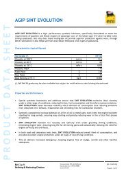
(1) Bolt an appropriate dial indicator or gauge to the<br />
engine flywheel so that the indicator is perpendicular<br />
to the face of the engine flywheel housing and the<br />
indicator stem is riding on the face of the flange.<br />
Refer to the adjacent drawing.<br />
(2) Rotate the engine flywheel, always keeping a<br />
thrust in same direction and note the face deviation of<br />
the engine flywheel housing flange.<br />
The face deviation must not exceed the figures given<br />
in Table 1.<br />
9
(3) With the indicator mounted as in the above<br />
paragraph, adjust the indicator stem so that it will<br />
ride on bore of the engine flywheel housing. Refer to<br />
the adjacent drawing.<br />
(4) Rotate the engine flywheel and note the bore<br />
eccentricity of the engine flywheel housing bore.<br />
Refer to Table 1.<br />
SAE Housing<br />
Size (SAE J617c)<br />
Table 1<br />
Flywheel Housing Tolerance<br />
Note: All figures are total indicator readings<br />
Face Deviation<br />
Bore Eccentricity<br />
mm Inch mm Inch<br />
00 0.305 0.012 0.305 0.012<br />
0 0.254 0.010 0.254 0.010<br />
1 0.203 0.008 0.203 0.008<br />
2 0.203 0.008 0.203 0.008<br />
(5) Bolt an appropriate dial indicator or gauge to the<br />
engine flywheel housing so that the indicator is<br />
perpendicular to the engine flywheel, and the<br />
indicator stem is riding on the inner face of the<br />
flywheel. Refer to the adjacent drawing.<br />
Rotate the flywheel.<br />
The variation of the face run out of the surface to<br />
which the driving ring is bolted should not exceed<br />
0.013 mm (0.0005 per inch of diameter).<br />
10
(6) With the indicator mounted as in the above<br />
paragraph, adjust the indicator stem so that it will<br />
ride on the driving ring pilot bore of the engine<br />
flywheel. Refer to the adjacent drawing.<br />
Rotate the flywheel.<br />
The driving ring pilot bore eccentricity of the<br />
engine flywheel should not exceed 0.13 mm (0,005<br />
inch) maximum total indicator reading, thrust on the<br />
flywheel should be in one direction at all times to<br />
obtain a correct reading.<br />
(7) Readjust the indicator so that stem will ride on<br />
the pilot bearing bore of the flywheel. Refer to the<br />
adjacent drawing.<br />
Rotate the flywheel.<br />
The eccentricity of the pilot bearing bore should not<br />
exceed 0.13 mm (0.005 inch) maximum total<br />
Indicator reading.<br />
Eccentricity between the driving ring pilot bore<br />
(Refer to step 6) and the pilot bearing bore should<br />
not exceed 0.2 mm (0.008 inch) total indicator<br />
reading.<br />
(8) With the indicator stem on the inside diameter of<br />
the driving ring pilot, apply pressure with a pry bar<br />
between the flywheel and flywheel housing on the<br />
opposite side from the indicator. Refer to the<br />
adjacent drawing.<br />
The indicator will measure vertical movement of<br />
engine flywheel. Maximum allowable movement is<br />
0.013 mm (0.005 inch).<br />
11
Installation<br />
A. Transmission Installation<br />
(1) Thoroughly clean flywheel and engine housing mating surfaces of any protective coatings,<br />
rust or other contaminants.<br />
(2) Install the input coupling drive ring to the engine flywheel and secure with appropriate high<br />
tensile bolts.<br />
(3) If not already done so fit rubber drive elements to the input of the <strong>transmission</strong> and on Centa<br />
couplings rotate the input so as to align the arrows for correct synchronous engagement<br />
(refer to Centa instructions supplied with the element).<br />
(4) Install the <strong>transmission</strong> on to the back of the engine.<br />
NOTE! Do not use the housing bolts to pull the <strong>transmission</strong> up to the engine. Should it not<br />
go on freely, remove the <strong>transmission</strong> and locate the source of the fouling and retry.<br />
(5) Secure the <strong>transmission</strong> to the engine housing using appropriate high tensile bolts.<br />
(6) Fit appropriate <strong>transmission</strong> mount pads using appropriate high tensile bolts.<br />
NOTE! In some countries the use of <strong>transmission</strong> mounts is not mandatory however… in the<br />
interest of safety and reliability under all conditions and circumstances Tonanco requires the<br />
use of <strong>transmission</strong> mounts. Failure to do so may void all and any warranties offered.<br />
(7) Install oil and water lines to oil cooler (if not already fitted).<br />
(8) Fit clutch engagement control cable<br />
WARNING! Failure to ensure full movement of the clutch engagement leaver to its detent<br />
position will damage and cause premature failure of the clutch packs. Excessive travel or<br />
over stoke of the lever can be just as harmful! Ensure positive selection is achieved in all<br />
positions<br />
(9) Install appropriate:<br />
Pressure monitoring equipment<br />
Temperature monitoring equipment<br />
It is recommended the electric gauge system be use when installing gauges in the helm or<br />
wheel house. Co-use of the supplied mechanical pressure gauge (fitted in the engine room) is<br />
also highly recommended as a backup pressure monitoring system in the event of an<br />
electrical fault.<br />
(10) FILL UNIT WITH CORRECT OIL AND TO THE CORRECT LEVEL!<br />
Refer to the lubricating oil section for correct oil selection.<br />
Re- check the oil level immediately after starting as significant amounts can be taken by the<br />
oil cooler and the lines.<br />
B. Alignment<br />
(1) Proper alignment of an engine and <strong>transmission</strong> is critical…..both during the initial<br />
installation and at frequent intervals during the life of the boat. It is rather common for a boat<br />
to change its form with various loads and with age. A bend is actually formed in the keel<br />
which changes the original engine and shaft alignment. The following steps may be taken to<br />
secure proper <strong>transmission</strong> alignment.<br />
C. Propeller Shaft Installation<br />
(1) A wire is run through shaft log and secured to a brace near the engine bed giving the wire a<br />
position equivalent to the shaft centre line.<br />
(2) The stern bearing and stuffing box are installed and bolted into position with the wire<br />
passing through each in the exact centre of the bore. With the bearing and stuffing box in<br />
place, the wire is then re-moved.<br />
12
(3) The propeller shaft is then installed in its proper position.<br />
(4) If intermediate shaft is used, it is blocked into position and its coupling. If there is an<br />
intermediate bearing in the line, this is installed and positioned with shims during the<br />
alignment process.<br />
(5) If a light shaft is used without an intermediate bearing, the shaft must be centred and<br />
supported to take out the droop while alignment of the flange couplings is being made.<br />
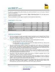
D. Engine and Transmission Alignment to Propeller Shaft<br />
(1) It is important to align the<br />
engine and <strong>transmission</strong>,<br />
only when the boat is afloat,<br />
and not in dry dock.<br />
During this alignment<br />
period, it is also advisable to<br />
fill the fuel tanks and add<br />
any other ballast that will be<br />
used when the boat is in<br />
service.<br />
With engine and<br />
<strong>transmission</strong> in position on<br />
the engine bed, arrangement<br />
must be made to have a<br />
controlled lifting or lowering of each of the four corners of the engine. If threaded holes are<br />
provided in each of the engine mounts, jacking screws can be used in them. The engine can<br />
be raised by screwing down, or lowered by backing off the desired amount. Steel plates must<br />
be inserted under the jacking screws so that the bolts will not damage the engine bed.<br />
(2) Lifting can also be accomplished by the use of chain hoists or properly placed jacks.<br />
Adjustable shims (commercially available) can simplify the whole problem, particularly for<br />
future realignment.<br />
(3) It may also be necessary to move the engine and <strong>transmission</strong><br />
from one side or the other on the bed to obtain horizontal<br />
alignment. This can be done with a jack placed horizontally<br />
between the engine and the foundation. At the same time, a<br />
straight edge is laid across the edges of the flanges at the top<br />
and side to check the parallel alignment of the coupling edges.<br />
(4) As the engine and <strong>transmission</strong> comes into its aligned position,<br />
it will be possible to match the output flange and propeller<br />
coupling, and prepare for bolting together. Care should be<br />
taken not to burr or mar this connection because the fit is very<br />
critical. Place a 0.05 mm (0.002 inch) feeler gauge between<br />
the flanges of the coupling. The feeler gauge is run completely<br />
around the coupling.<br />
(5) Then the <strong>transmission</strong> flange coupling is rotated 90°, 180°and 270°with the feeler blade<br />
being run around the flange again in each successive position. If the alignment is correct, the<br />
feeler gauge will fit snugly, with the same tension, all around the flange coupling.<br />
13
(6) If the alignment varies during rotation, then further alignment is necessary, or the<br />
<strong>transmission</strong> and shaft couplings should be checked for improper face run out. Face run out<br />
on the <strong>transmission</strong> output flange can usually be corrected by repositioning the coupling on<br />
its spline. Shaft coupling run out is usually due to inaccuracy of taper fit or key interference.<br />
(7) Some boats are not structurally rigid and some carry their load in such a way that they will<br />
“hog” or go out normal shape with every loading and unloading. Where this condition exists,<br />
it may be necessary to make a compromise between the top and bottom coupling clearance<br />
by leaving a greater clearance at the bottom of the <strong>transmission</strong> output flange and propeller<br />
coupling. This clearance might be 0.127 to 0.178 mm (0.005 to 0.007 inch) while the top<br />
would maintain standard 0.05 mm (0.002 inch).<br />
(8) During the process of securing final alignment, it may be necessary to shift the engine many<br />
times. When it becomes apparent that the alignment is reasonably close, the holes for the lag<br />
studs are marked and drilled. Then with final alignment secured, the necessary steel or<br />
hardwood shims are made up and the engine and <strong>transmission</strong> is fastened in place. The<br />
alignment is then rechecked, and if satisfactory, the coupling is bolted together.<br />
(9) Although it is not as necessary to align a flexible coupling as accurately as a solid coupling,<br />
the closer it is in the initial alignment, the more vibration-free it will be. The most accurate<br />
method of alignment is to align the shaft on to the <strong>transmission</strong> with flexible coupling out of<br />
the system. This can be done with a spacer the same size as the coupling but not flexible in<br />
nature, Flexible couplings are used only for noise and vibration dampening.... and not to<br />
correct inadequate alignment.<br />
(10) When a heavy boat is dry-docked, it naturally undergoes some bending. Therefore, it is<br />
always good practice to unbolt the <strong>transmission</strong> coupling and prevent bending of the shaft.<br />
CAUTION!!<br />
BE SURE THE TRANSMISSION IS FILLED WITH<br />
OIL BEFORE STARTING.<br />
And rechecked immediately after starting for the first time!<br />
SEE PAGE 25 FOR CORRECT OIL AND FILLING PROCEDURES.<br />
14
SECTION 6<br />
Operation<br />
GENERAL<br />
A. Description<br />
This <strong>transmission</strong> has forward, neutral and reverse positions obtained by means of<br />
the selector valve. When these positions are selected, the selector valve directs highpressure<br />
oil through internal passages to operate the clutches.<br />
B. Hydraulic System<br />
1. Oil is pumped through the system by the gear-type pump. The oil is taken<br />
from the sump through the strainer by the pump, and discharged through the<br />
heat exchanger and filter to the selector valve. The oil enters the pressure<br />
regulating area of the valve where main pressure is regulated by cascading<br />
excess oil into the lube circuit. Lube oil is distributed through fixed<br />
controlled orifices to lubricate bearings and cool the clutches. Lube pressure<br />
is controlled by a piston in the oil return pipe assembly.<br />
SELECTOR VALVE ASSEMBLY<br />
2. In neutral, the inlet ports to the clutches are blocked, the clutches are<br />
disengaged and the area behind the clutch pistons is open to sump. Oil is<br />
distributed through the lubrication system.<br />
3. When the selector valve is shifted to engage either clutch, the selector valve<br />
directs main pressure to engage the selected clutch pack. Oil is also directed<br />
through a port in the selector valve spool to a fixed orifice in the orifice<br />
plate causing a controlled flow of oil to unseat the rate-of-rise piston and<br />
move it to seat on a shoulder in the rate-of-rise piston bore compressing the<br />
pressure regulator springs. This progressively increases the clutch engaging<br />
pressure causing the clutches to engage at a controlled rate. Any excess oil<br />
becomes lube oil.<br />
4. The selector valve allows only one clutch to be engaged at a time, and the<br />
oil from the disengaged clutch is dumped to sump. When a clutch is<br />
disengaged, pressure head existing behind the clutch apply piston is relieved<br />
to sump through the selector valve. This allows the return springs to move<br />
the clutch piston to the disengaged position to prevent clutch drag.<br />
A. Description<br />
B. Operation<br />
The selector valve assembly contains passages and ports for the <strong>transmission</strong><br />
and direction of pressurized oil within the hydraulic system. It is the<br />
function of the pressure rate control piston within the selector valve<br />
assembly to provide a rapid, yet smooth, pressure rise for the hydraulic<br />
system during clutch engagement.<br />
To achieve the maximum service life of the <strong>transmission</strong> all shifts should be<br />
carried out with the engine speed at low idle. It is preferable when changing<br />
propeller shaft direction to allow the shaft to slow or become stationary<br />
before engaging the next desired direction.<br />
15
SECTION 7<br />
Emergency Mechanical Lock-up<br />
(Come home feature)<br />
An emergency lockup feature has been designed into the clutch packs of all Tonanco units in<br />
the event of hydraulic system failure. Simply, this feature is a mechanical lock-up of the<br />
clutch to enable the boat to return to port.<br />
This feature is intended to be used on single engine vessels and as a last resort to gain<br />
propulsion. On multiple engine vessels it is encouraged to use the other good engine to<br />
return to port for repairs.<br />
Most common reasons for use of the come home screws are:<br />
‣ Loss of hydraulic pump drive<br />
‣ Hydraulic pump failure<br />
‣ Loss of lubricating oil<br />
‣ Broken, worn or blown sealing rings<br />
‣ Clutch pack piston failure<br />
It is highly recommend that you, your crew and any person that may have to undertake<br />
this procedure whilst at sea, practice and be familiar with the procedure.<br />
Direction of rotation for forward or ahead motion should be clearly marked on or near the<br />
propeller shaft in the event of an emergency and to save valuable time. It is also<br />
recommended that a tool set be assigned, marked clearly and located in an accessible<br />
location to undertake this and any other emergency procedure.<br />
INSTRUCTIONS FOR USE<br />
1. TURN OFF THE ENGINE! Serious injury to personnel may be resulted, if the engine is left<br />
running.<br />
2. Secure the propeller shaft to prevent rotation. Wave action or motion of the vessel may cause<br />
the propeller to back drive and turn the shaft. If this occurs when attempting to engage the<br />
clutch it will cause the pack to rotate damaging the screws, the tooling and may render the<br />
unit completely unusable.<br />
3. Disconnect the selector control cable to prevent any accidental engagement. And secure it in<br />
the neutral position!<br />
4. If not already done so, determine the direction of output or propeller shaft rotation and the<br />
associated clutch pack for this direction. Generally a single engine vessel uses the input shaft<br />
clutch pack for forward direction. This is the shaft located directly behind the crankshaft.<br />
5. Remove the two access plugs from the manifold over the appropriate forward clutch<br />
location. (Locations of the plugs for the come home screws are shown on the following<br />
pages)<br />
16
6. Rotate engine by hand or lever (Do not use the starter motor) until the come home setscrews<br />
are visible through the access plugholes. A flashlight or other source of light may be<br />
required to see these screws.<br />
7. Use an appropriate hex-wrench or hex-driver (see below for correct tool selection) to<br />
alternately tighten the two (2) come-home screws (1/4 of a turn each time to prevent the<br />
piston from jamming) in a standard clockwise direction until mechanical lock-up of the<br />
clutch is attained. Make sure they are as tight as possible but not excessively.<br />
8. Remove the tool and replace the two access plugs.<br />
9. The drive and driven clutch plates are now mechanically clamped together for solid drive<br />
through clutch. The <strong>transmission</strong> is always in gear.<br />
CAUTION<br />
Should there have been a hydraulic oil leak causing the come home feature to be used, do<br />
not block any lines or cap off the hoses. This may hydraulic the oil charge pump causing a<br />
catastrophic pump failure or high pressure oil rupture. Minimise any leak or divert the line<br />
into a suitable container. Do not allow oil to leak or flow onto any ignition sources.<br />
Operate engine at reduced speed and do not attempt to use hydraulic engaging during solid drive.<br />
When using mechanical lock-up with a twin-engine arrangement, be sure the direction of drive of the<br />
two units is compatible.<br />
Tools<br />
TM729 Series<br />
Crescent wrench or adjustable spanner for access plugs (1/2” male square heads)<br />
5mm Allen or hex drive T wrench or key for come home screws<br />
TM828 to TM989 Series<br />
8mm Allen or hex drive T wrench or key for access plugs<br />
5mm Allen or hex drive T wrench or key for come home screws<br />
TM1009<br />
10mm Allen or hex drive T wrench or key for access plugs<br />
8mm Allen or hex drive T wrench or key for come home screws<br />
Repair the <strong>transmission</strong> as soon as possible.<br />
17
TM729 Shallow & Deep Case<br />
Note only the forward clutch pack can be engaged on the TM729 series!<br />
PROPELLER SHAFT ROTATIONS<br />
Opposite to engine rotation<br />
ONLY<br />
18
TM828 Shallow & Deep Case Models<br />
PROPELLER SHAFT ROTATIONS<br />
Opposite to engine rotation<br />
Same as engine rotation<br />
19
TM939 Shallow & Deep Case Models<br />
PROPELLER SHAFT ROTATIONS<br />
Opposite to engine rotation<br />
Same as engine rotation<br />
20
TM989 Shallow & Deep Case Models<br />
TM 1009 Model<br />
PROPELLER SHAFT ROTATIONS<br />
Opposite to engine rotation<br />
Same as engine rotation<br />
21
SECTION 8<br />
Oil & Lubrication<br />
OIL CAPACITIES<br />
TM729 Shallow Case: Approximately 10.2 litres (2.7 gal US)<br />
Deep Case: Approximately 11.4 litres (3.0 gal US)<br />
TM828 Shallow Case: Approximately 23.8 litres (6.3 gal US)<br />
Deep Case: Approximately 28.4 litres (7.5 gal US)<br />
TM939 Shallow Case: Approximately 20.0 litres (5.3 gal US)<br />
Deep Case: Approximately 25.0 litres (6.6 gal US)<br />
TM989 Shallow Case: Approximately 25.0 litres (6.6 gal US)<br />
Deep Case: Approximately 37.0 litres (9.7 gal US)<br />
TM1009 Approximately 65.1 litres (17.2 gal US)<br />
With all models check the oil level is on the full mark of the oil gauge at idle speed.<br />
OIL RECOMMENDATIONS<br />
Use only SAE-API service class CD engine oil certified to meet TO-2 <strong>transmission</strong> oil specification<br />
or type C-3 <strong>transmission</strong> fluid. Also approved is SAE-API service class CC engine oil.<br />
OIL VISCOSITY<br />
Sump temperature,<br />
also oil temperature in to the heat exchanger<br />
During start-up Steady operating conditions<br />
Recommended oil<br />
viscosity<br />
Below 65.5 ゚C (150 ゚F)<br />
This operating condition<br />
is not approved<br />
1.7 ゚C (35 ゚F) Min 65.6 - 85 ゚C (150 - 185 ゚F) SAE viscosity #40 oil<br />
10 ゚C (50 ゚F) Min 80 - 100 ゚C (175 - 210 ゚F) SAE viscosity #50 oil<br />
Above 100 ゚C (210 ゚F)<br />
This operating condition<br />
is not approved<br />
NOTE: Multi viscosity oils (i.e. l0W-20 etc.) should not be used in the <strong>transmission</strong>.<br />
OIL LEVEL<br />
Oil level should be checked daily by the oil level gauge in the main housing. Check the oil<br />
level with the engine running at low idle and the <strong>transmission</strong> in neutral. Oil temperature should be<br />
in normal operating range prior to checking the oil level.<br />
OIL CHANGE INTERVAL<br />
Replace oil after every six months or 1000 hours of operation, whichever occurs first.<br />
22
OIL STRAINER<br />
Remove and clean after first 100 hours and thereafter every 1000 hours of operation.<br />
OIL FILTER ELEMENT (excludes TM729)<br />
Replace after first 100 hours and thereafter every 1000 hours of operation.<br />
OIL PRESSURES<br />
Models: TM729, TM828, TM939 and TM989.<br />
Engine<br />
Speed<br />
1800RPM<br />
SELECTOR POSITION<br />
Lube pressure<br />
FORWARD NEUTRAL REVERSE<br />
Kg/cm² PSI Kg/cm² PSI Kg/cm² PSI Kg/cm² PSI<br />
Minimum 12.0 170 3.0 43 12.0 170 1.5 21<br />
Maximum 15.0 213 6.0 85 15.0 213 2.0 28<br />
Oil Temperature 82.2 ゚C (180 ゚F)<br />
Model: TM1009 only.<br />
Engine<br />
Speed<br />
1800RPM<br />
SELECTOR POSITION<br />
Lube pressure<br />
FORWARD NEUTRAL REVERSE<br />
Kg/cm² PSI Kg/cm² PSI Kg/cm² PSI Kg/cm² PSI<br />
Minimum 16.7 237 4.9 70 16.7 237 1.5 21<br />
Maximum 18.5 263 6.9 100 18.5 263 2.0 28<br />
Oil Temperature 82.2 ゚C (180 ゚F)<br />
23
SECTION 9<br />
Preventative Maintenance<br />
1. GENERAL<br />
1. Lubrication<br />
Grease the oil seals on the output end of the output shaft through the grease fitting with<br />
good quality grease, Apply grease once a week if there is water in the bilge. Grease the<br />
seals at the same time the oil is changed if the bilge is dry. No other lubrication is<br />
required beyond the daily oil check.<br />
2. Overhaul Interval<br />
I. Some maintenance or repairs can be made without removing the <strong>transmission</strong> from<br />
the boat. It is advisable that if any substantial repairs are required and carried out in<br />
the vessel that these are done as a temporary measure and a full workshop overhaul<br />
be considered in the near future<br />
II.<br />
A complete overhaul of the <strong>transmission</strong> should be made at the same time that the<br />
engine is overhauled.<br />
2. OIL SYSTEM<br />
1. Oil Level<br />
I. The oil level should be checked daily by the oil level gauge in the main housing.<br />
Check the oil level with the engine running at low idle and the <strong>transmission</strong> in<br />
neutral oil temperature should be in normal operating range prior to checking oil<br />
level.<br />
II.<br />
Oil and Filter Change Interval (Maximum).<br />
a. With a new <strong>transmission</strong>, change the initial oil within 100 hours operation.<br />
Thereafter the oil and oil filter must be changed every six months or 1000<br />
hours of operation, whichever comes first.<br />
b. For a rebuild <strong>transmission</strong>, check the filter strainer and element after 8 hours<br />
operation. If the filter is clean, re-install and then change filter element after<br />
1000 hours. If either of the filters are dirty or have contaminates, clean the<br />
strainer and change the element. Operate another 8 hours. Check again.<br />
Continue this cycle until the filter is clean and then change the element after<br />
1000 hours service or more often if conditions warrant.<br />
c. For vessels in long term storage (more than one year) drain and refill the oil<br />
before recommencement of service. At the commencement of the long term<br />
storage it is advisable fill the <strong>transmission</strong> unit completely (to the top of the<br />
dipstick tube only). This expels any air and prevents corrosive condensation<br />
building up over time. It is also recommended that the propeller shaft be<br />
rotated by hand every three to four months as well. Be sure to remove the<br />
excess oil before starting the engine!<br />
24
2. Draining<br />
I. Drain the oil from the <strong>transmission</strong> by following means either of the following:<br />
a. Gravity Drain: Drain the <strong>transmission</strong> by removing the square-head pipe<br />
plug on the rear side at the bottom cover.<br />
3. Filling<br />
b. Suction Drain: A suction pump can be used to drain the oil from the<br />
<strong>transmission</strong> sump.<br />
I. Prior to filling, make sure of the drain plug is secured in place. Remove the<br />
breather assembly from the top of the main housing assembly and then pour oil<br />
through the breather opening.<br />
II.<br />
III.<br />
IV.<br />
Fill the sump with the appropriate amount of oil for the type of casing (Deep or<br />
shallow case) with the proper weight and type of oil. See section 8 for proper oil.<br />
Start the engine and let it idle with <strong>transmission</strong> in neutral until oil is circulated<br />
throughout the hydraulic system.<br />
With the oil at operating temperature, <strong>transmission</strong> in neutral and the engine<br />
running at low idle, check the oil level with the oil gauge. Add oil as necessary to<br />
bring the oil level up to "Full" on the oil gauge.<br />
4. Suction Oil Filter<br />
Remove and clean the pump suction oil filter element at every oil change or sooner<br />
if necessary. Replace the cartridge type oil filter with new filter at the same time.<br />
5. Periodic Visual Inspection<br />
I. Check the mountings for tightness or damage such as cracks. Tighten loose<br />
mountings and replace damaged parts.<br />
II.<br />
III.<br />
IV.<br />
Heat exchanger. Inspect heat exchanger oil lines for leaky connection, sponginess,<br />
kinks, cracks or other damage. Replace any damaged lines.<br />
Rubber drive blocks and elements. Annually remove the ventilation cover on the<br />
front housing, and inspect the rubber blocks for wear or damage. Replace worn,<br />
damaged or hard rubber blocks or drive elements.<br />
Oil seals: Periodically, inspect the driveline and input and output shaft oil seals for<br />
leakage. Replace parts as required.<br />
V. Pressure gauge assembly: Periodically, inspect the pressure gauge for damage.<br />
Replace damaged gauge. If the gauge is suspected of being inaccurate, replace the<br />
gauge with one of proven accuracy to determine the extent of malfunction<br />
25
SECTION 10<br />
Trouble shooting<br />
This section of the maintenance <strong>manual</strong> has been prepared to assist maintenance personnel in trouble<br />
shooting the equipment. When trouble shooting any equipment, always remember to consider all<br />
aspects of the entire power package and never assume it is the fault of only one part. Consult with<br />
your nearest authorised repairer should any problem persist.<br />
The trouble-shooting table is organized in three columns. Proper use of the table will aid in the rapid<br />
determination and repair of any functional difficulties that may occur.<br />
Symptom Cause Remedy<br />
1.<br />
Low clutch apply<br />
oil pressure.<br />
2.<br />
No oil pressure.<br />
3.<br />
High oil<br />
pressure.<br />
1-1. Partially clogged oil<br />
strainer.<br />
1-2. Stuck pressure<br />
regulation piston in<br />
selector valve<br />
assembly.<br />
1-3. Broken seal rings<br />
in clutches.<br />
1-4. Emergency (Lock-<br />
Up) setscrew loose or<br />
missing.<br />
1-1. Remove and clean oil strainer.<br />
1-2. Disassemble the valve assembly and<br />
clean the piston.<br />
1-3. Remove the manifold and disassemble<br />
the clutches. Replace broken seal rings in<br />
piston carrier.<br />
1-4. Remove the emergency lock-up<br />
setscrew access plugs. Tighten a loose<br />
emergency lock-up setscrew by turning<br />
counter clockwise or replace setscrew.<br />
1-5. Remove oil pump assembly. Replace<br />
1-5. Damaged or worn<br />
pump assembly. damaged or worn oil pump assembly.<br />
1-6. Incorrect linkage 1-6. Adjust the linkage so that selector valve<br />
installed on selector system is indexed properly by detent.<br />
valve assembly.<br />
1-7. Clogged or plugged 1-7. Remove orifice plate cover. Clean<br />
orifice in orifice plate of parts.<br />
selector valve.<br />
1-8. Faulty pressure 1-8. Replace pressure gauge.<br />
gauge.<br />
2-1. Oil pump suction 2-1. Remove and clean.<br />
strainer blocked.<br />
2-2. Oil level low. 2-2. Check oil level. Find and correct the<br />
leak.<br />
2-3. Air leak on suction 2-3. Check hose, gaskets and seals for<br />
side of pump.<br />
leakage. Replace parts causing leakage.<br />
2-4. Pump drive on 2-4. Disassemble and repair as required.<br />
reverse clutch shaft<br />
broken.<br />
2-5. Oil pump defective. 2-5. Replace oil pump.<br />
3-1. Stuck pressure 3-1. Remove and clean regulating piston.<br />
regulation piston in<br />
selector valve<br />
assembly.<br />
3-2. Faulty spring. 3-2. Check and replace spring.<br />
26
Symptom Cause Remedy<br />
4.<br />
Overheating.<br />
5.<br />
Excessive<br />
noise.<br />
6.<br />
No neutral.<br />
7.<br />
Harsh<br />
engagement.<br />
4-1. Improper oil level. 4-1. Check and fill with proper oil to the<br />
correct level.<br />
4-2. Faulty heat 4-2. Inspect, repair or replace heat<br />
exchanger.(if used). exchanger.<br />
4-3. Clutches slipping. 4-3. Check clutch apply oil pressure. If<br />
pressure is normal, remove, disassemble<br />
and repair slipping clutch.<br />
4-4. Bearing failure. 4-4. Overhaul <strong>transmission</strong>.<br />
4-5. Bearing<br />
4-5. Check cooling oil to the bearing.<br />
Overheating.<br />
Recheck bearing endplay.<br />
4-6. Insufficient cooling 4-6. Inside diameter of water lines too small.<br />
water flow.<br />
Replace lines with larger inside diameter<br />
hoses. Check for obstructions.<br />
4-7. Clutch plates 4-7. Replace clutch plates.<br />
warped.<br />
5-1. Bearing failure 5-1. Overhaul <strong>transmission</strong>!<br />
5-2. Worn or damaged<br />
rubber input drive<br />
blocks or elements.<br />
6-1. Clutch plates<br />
warped.<br />
6-2. Selector valve<br />
incorrectly position.<br />
Valve not in detent.<br />
7-1. Orifice plate Steel<br />
ball in selector valve not<br />
seating properly.<br />
7-2. Regulating or<br />
control piston stuck.<br />
5-2. Remove <strong>transmission</strong>. Replace worn or<br />
damaged rubber drive blocks or elements.<br />
6-1. Replace clutch plates. Overhaul clutch<br />
piston assembly.<br />
6-2. Check and adjust selector valve control<br />
linkage.<br />
7-1. Remove orifice plate cover. Clean<br />
parts. Replace parts if necessary.<br />
7-2. Disassembly selector valve. Clean<br />
parts. Replace parts is necessary.<br />
8.<br />
Low lube oil<br />
pressure.<br />
.<br />
8-1. Pump GPM output<br />
too low.<br />
8-2. Pump suction<br />
strainer blocked.<br />
8-3. Air leak on suction<br />
side of pump.<br />
8-4. Lube regulator<br />
valve stuck.<br />
8-1. Replace oil pump.<br />
8-2. Remove, clean, inspect and install the<br />
oil filter element.<br />
8-3. Inspect for and correct air leak.<br />
8-4. Remove and clean or replace parts as<br />
necessary.<br />
27
SECTION 11<br />
Replacement Parts Ordering<br />
A. Identification<br />
Identification of your unit is most important, without proper identification it is very difficult to<br />
supply correct replacement parts. This can lead to incorrect supply which in turn causes undue stress<br />
and expense to all parties concerned.<br />
Tonanco <strong>transmission</strong>s are easily identified by the use of their name plate. The name plate is located<br />
on the port side of the unit and if missing the serial number and ratio is imprinted into the main<br />
housing under the location of the name plate.<br />
Please take the time to note and record the model, serial number and ratio. Provision has been made<br />
in the front cover of this <strong>manual</strong> for you to record this information but it is also recommended that<br />
the information be stored at a secure secondary location.<br />
B. Sourcing<br />
Renewal parts, service parts kits and workshop repairs may be obtained from your authorized<br />
distributor or service dealer, or directly from the <strong>transmission</strong> manufacturer. Refer to the contact<br />
pages on page 29.<br />
C. Method<br />
When ordering a service part please provide the following information:<br />
Model number<br />
Ratio<br />
Serial number<br />
The part number (where possible)<br />
The description of the part<br />
The quantity required<br />
Do not use the word "complete", as only the parts number determines the components that will be<br />
furnished. Also do not designate the quantity by "sets" but specify the number of parts required by<br />
part number.<br />
Also, it is imperative that the model and serial numbers of the units be included. These numbers will<br />
always be found stamped on the <strong>marine</strong> <strong>transmission</strong> nameplate.<br />
Tonanco only produces gasket kits, seal and lock sets and control valve kits only. Some Tonanco<br />
dealer‟s suppliers may be able to provide specialist overhaul kits however refer to your nearest<br />
Tonanco dealer for availability of such product lines.<br />
28
GLOBAL<br />
(HEAD OFFICE) USA<br />
Tonanco Global<br />
P O Drawer 1707<br />
Lake Charles LA 70602<br />
USA<br />
PH 1-800-909-8718<br />
Fax (337) 433-9744<br />
sales@gdsco.net<br />
(Factory) JAPAN<br />
Tonan Corporation<br />
No. 992 Shishiko<br />
USHIKU IBARAKI<br />
300-1231<br />
Ph: 029- 872-1036<br />
Fax: 029- 872-8444<br />
tonan@ca.wakwak.com<br />
Dealers and distributors<br />
USA<br />
New Zealand<br />
Global Diesel Service<br />
<strong>TransDiesel</strong><br />
1903 West McNab Road Unit 10, 148-158 Beaumont St<br />
Pompano Beach (Florida)<br />
Westhaven, Auckland<br />
FL 33069 Ph +64 9 379 0260<br />
Ph: (954) 971-6600 Fax +64 9 303 1976<br />
paulp@transdiesel.co.nz<br />
Australia<br />
North Star Transmissions<br />
1/830 Knight Road<br />
North Albury, 2640<br />
New South Wales<br />
Ph: +61 2 6040 1900<br />
Fax: +61 2 6040 3499<br />
sales@nstco.com.au<br />
29