IFMA Data Sheet/Manual PDF - Farnell
IFMA Data Sheet/Manual PDF - Farnell
IFMA Data Sheet/Manual PDF - Farnell

Create successful ePaper yourself
Turn your PDF publications into a flip-book with our unique Google optimized e-Paper software.
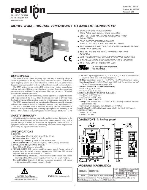
Bulletin No. <strong>IFMA</strong>-E<br />
Drawing No. LP0340<br />
Released 5/06<br />
Tel +1 (717) 767-6511<br />
Fax +1 (717) 764-0839<br />
www.redlion.net<br />
MODEL <strong>IFMA</strong> - DIN-RAIL FREQUENCY TO ANALOG CONVERTER<br />
<br />
<br />
<br />
<br />
<br />
<br />
<br />
<br />
SIMPLE ON-LINE RANGE SETTING<br />
(Using Actual Input Signal or Signal Generator)<br />
USER SETTABLE FULL SCALE FREQUENCY FROM<br />
1 Hz to 25 KHz<br />
FOUR OUTPUT OPERATING RANGES<br />
(0 to 5 V, 0 to 10 V, 0 to 20 mA, and 4 to 20 mA)<br />
PROGRAMMABLE INPUT CIRCUIT ACCEPTS OUTPUTS FROM A<br />
VARIETY OF SENSORS<br />
85 to 250 VAC and 9 to 32 VDC POWERED VERSIONS<br />
AVAILABLE<br />
LOW FREQUENCY CUT-OUT AND OVERRANGE INDICATION<br />
3-WAY ELECTRICAL ISOLATION (POWER/INPUT/OUTPUT)<br />
INPUT AND OUTPUT INDICATION LEDs<br />
UL Recognized Component,<br />
File # E137808<br />
DESCRIPTION<br />
The Model <strong>IFMA</strong> accepts a frequency input, and outputs an analog voltage or<br />
current in proportion to the input frequency, with 0.1% accuracy. The full scale<br />
input frequency can be set to any value from 1 Hz to 25 KHz, either with a<br />
frequency source, or digitally with the on-board rotary switch and push-button.<br />
The <strong>IFMA</strong> utilizes a seven position DIP switch, a rotary switch, a push-button<br />
and two indication LEDs to accomplish input circuit configuration, operational<br />
parameter set-up, and Input/Output indication. The input circuitry is DIP switch<br />
selectable for a variety of sources.<br />
The indication LEDs are used during normal operation to display the input<br />
and output status of the <strong>IFMA</strong>. These LEDs are also used to provide visual<br />
feedback to the user of the existing parameter settings during parameter set-up.<br />
The <strong>IFMA</strong> operates in one of four output modes. The programmable minimum<br />
and maximum response times provide optimal response at any input frequency.<br />
The unit is equipped with a universal mounting foot for attachment to<br />
standard DIN style mounting rails, including top hat profile rail according to EN<br />
50 022 - 35 x7.5 and 35 x 15, and G profile rail according to EN 50 035 - G 32.<br />
SAFETY SUMMARY<br />
All safety related regulations, local codes and instructions that appear in the<br />
manual or on equipment must be observed to ensure personal safety and to<br />
prevent damage to either the instrument or equipment connected to it. If<br />
equipment is used in a manner not specified by the manufacturer, the protection<br />
provided by the equipment may be impaired.<br />
SPECIFICATIONS<br />
1. POWER:<br />
AC Operation: 85 to 250 VAC, 48 to 62 Hz; 6.5 VA<br />
DC Operation: 9 to 32 VDC; 2.5 W<br />
Power Up Current: Ip = 600 mA for 50 msec. max.<br />
2. SENSOR POWER: (AC version only) +12 VDC ±25% @ 60 mA max.<br />
3. OPERATING FREQUENCY RANGE:<br />
From 0 Hz to 25 KHz; user selectable.<br />
4. SIGNAL INPUT: DIP switch selectable to accept signals from a variety of<br />
sources, including switch contacts, outputs from CMOS or TTL circuits,<br />
magnetic pickups, and all standard RLC sensors.<br />
Current Sourcing: Internal 1 KΩ pull-down resistor for sensors with current<br />
sourcing output. (Max. sensor output current = 24 mA @ 24 V output.)<br />
Current Sinking: Internal 3.9 KΩ pull-up resistor for sensors with current<br />
sinking output. (Max. sensor current = 3 mA.)<br />
Low Bias: Input trigger levels V IL = 0.25 V, V IH = 0.75 V; for increased<br />
sensitivity when used with magnetic pickups.<br />
Hi Bias: Input trigger levels V IL = 2.5 V, V IH = 3.0 V; for logic level signals.<br />
Max. Input Signal: ±90 V; 2.75 mA max. (With both Current Sourcing and<br />
Current Sinking resistors switched off.)<br />
5. SIGNAL VOLTAGE OUTPUT (Selectable):<br />
0 to 5 VDC @ 10 mA max.<br />
0 to 10 VDC @ 10 mA max.<br />
6. SIGNAL CURRENT OUTPUT (Selectable):<br />
0 to 20 mA @ 10 VDC min.<br />
4 to 20 mA@ 10 VDC min.<br />
7. OUTPUT COMPLIANCE:<br />
Voltage: 10 V across a min. 1KΩ load (10 mA). Factory calibrated for loads<br />
greater than 1 MΩ.<br />
Current: 20 mA through a max. 500Ω load (10 VDC).<br />
8. ACCURACY: ±0.1% of full scale range (±0.2% for 0 to 5 VDC range).<br />
9. RESOLUTION:<br />
Voltage : 3.5 mV min.<br />
Current: 5 µA min.<br />
DIMENSIONS In inches (mm)<br />
ORDERING INFORMATION<br />
CAUTION: Risk of Danger.<br />
Read complete instructions prior to<br />
installation and operation of the unit.<br />
CAUTION: Risk of electric shock.<br />
MODEL NO. DESCRIPTION<br />
PART NUMBERS FOR AVAILABLE<br />
SUPPLY VOLTAGES<br />
9 to 32 VDC 85 to 250 VAC<br />
<strong>IFMA</strong> Pulse Rate to Analog Converter <strong>IFMA</strong>0035 <strong>IFMA</strong>0065<br />
For more information on Pricing, Enclosures & Panel Mount Kits refer to the<br />
RLC Catalog or contact your local RLC distributor.<br />
1
SPECIFICATIONS (Cont’d)<br />
10. RESPONSE TIME: 5 msec +1 period to 10 sec +1 period; user selectable<br />
11. INPUT IMPEDANCE: 33 KΩ min. with the sink and source DIP switches<br />
in the OFF position (See Block Diagram).<br />
12. INPUT AND POWER CONNECTIONS: Screw in terminal blocks.<br />
13. ISOLATION BREAKDOWN VOLTAGE (Dielectric Withstand): 2200<br />
V between power & input, and power & output; 500 V between input &<br />
output for 1 minute.<br />
14. CERTIFICATIONS AND COMPLIANCES:<br />
SAFETY<br />
UL Recognized Component, File #E137808, UL508, CSA C22.2 No. 14<br />
Recognized to U.S. and Canadian requirements under the Component<br />
Recognition Program of Underwriters Laboratories, Inc.<br />
IECEE CB Scheme Test Certificate # UL1683A-176645/USA,<br />
CB Scheme Test Report # 97ME50135-042297<br />
Issued by Underwriters Laboratories, Inc.<br />
IEC 61010-1, EN 61010-1: Safety requirements for electrical equipment<br />
for measurement, control, and laboratory use, Part 1.<br />
EMC EMISSIONS:<br />
Meets EN 50081-2: Industrial Environment.<br />
CISPR 11 Radiated and conducted emissions<br />
EMC IMMUNITY:<br />
Meets EN 50082-2: Industrial Environment.<br />
ENV 50140 - Radio-frequency radiated electromagnetic field 1<br />
ENV 50141 - Radio-frequency conducted electromagnetic field<br />
EN 61000-4-2 - Electrostatic discharge (ESD) 2<br />
EN 61000-4-4 - Electrical fast transient/burst (EFT)<br />
EN 61000-4-8 - Power frequency magnetic field<br />
Notes:<br />
1. For operation without loss of performance:<br />
Unit is mounted on a rail in a metal enclosure (Buckeye SM7013-0 or<br />
equivalent) and I/O cables are routed in metal conduit connected to<br />
earth ground.<br />
2. This device was designed for installation in an enclosure. To avoid<br />
electrostatic discharge, precautions should be taken when the device is<br />
mounted outside an enclosure. When working in an enclosure (ex. making<br />
adjustments, setting switches, etc.) typical anti-static precautions should<br />
be observed before touching the unit.<br />
Refer to the EMC Installation Guidelines section of this bulletin for<br />
additional information.<br />
15. ENVIRONMENTAL CONDITIONS:<br />
Operating Temperature: 0 to 50°C<br />
Storage Temperature: -40 to 80°C<br />
Operating and Storage Humidity: 85% max. (non-condensing) from 0°C<br />
to 50°C.<br />
Altitude: Up to 2000 meters<br />
16. CONSTRUCTION: Case body is green, high impact plastic. Installation<br />
Category II, Pollution Degree 2<br />
17. WEIGHT: 6 oz. (0.17 Kg)<br />
BLOCK DIAGRAM<br />
OVERVIEW<br />
The Model <strong>IFMA</strong> continuously monitors a frequency input and outputs a<br />
voltage or current signal in proportion to the input signal. The output is accurate<br />
to ±0.1% of full scale for Operating Modes 2, 3, and 4. Operating Mode 1 is<br />
accurate to ±0.2% of full scale. The green Input LED blinks at the rate of the<br />
input frequency. At about 100 Hz, the Input LED will appear to be solid on. At<br />
very low frequencies, the Input LED blinks slowly and may also appear to be<br />
solid on. A loss of signal may also cause the Input LED to remain on, depending<br />
on the DIP switch set-up. In this case, the red LED also turns on.<br />
The Minimum Response Time parameter sets the minimum update time of the<br />
output. The actual response time is the Minimum Response Time plus up to one<br />
full period of the input signal. The <strong>IFMA</strong> counts the negative edges occurring<br />
during the update time period, and computes the average frequency value for that<br />
time. This action filters out any high frequency jitter that may be present in the<br />
input signal. The longer the Minimum Response Time, the more filtering occurs.<br />
The Maximum Response Time parameter sets the Low Frequency Cut-out<br />
response time for the unit. If a new edge is not detected within the time specified<br />
by the Maximum Response Time setting, the unit sets the output to the<br />
existing Low Frequency Cut-out Value setting depending on the selected range<br />
and calibration setting.<br />
The unit also indicates Low Frequency Cut-out by turning ON the output<br />
LED. The Maximum Response Time can be set shorter than the Minimum<br />
Response Time. In this case, as long as the input signal period is shorter than the<br />
Maximum Response Time, the unit continues to indicate the input frequency at<br />
its output. But, if the input period at any time exceeds the Maximum Response<br />
Time, the unit immediately takes the output to the Low Frequency Cut-out<br />
Value, regardless of the Minimum Response Time setting.<br />
The <strong>IFMA</strong> is calibrated at the factory for all of the selected ranges. However,<br />
the user can adjust the minimum calibration to any value less than the Full Scale<br />
value, and the Full Scale value to any value greater than the minimum value. If<br />
the minimum and full scale values are brought closer together, the accuracy of the<br />
unit decreases proportionate to the decreased range of the unit (See Calibration).<br />
2
EMC INSTALLATION GUIDELINES<br />
Although this unit is designed with a high degree of immunity to<br />
ElectroMagnetic Interference (EMI), proper installation and wiring methods<br />
must be followed to ensure compatibility in each application. The type of the<br />
electrical noise, source or coupling method into the unit may be different for<br />
various installations. The unit becomes more immune to EMI with fewer I/O<br />
connections. Cable length, routing, and shield termination are very important<br />
and can mean the difference between a successful installation or troublesome<br />
installation.<br />
Listed below are some EMC guidelines for successful installation in an<br />
industrial environment.<br />
1. Use shielded (screened) cables for all Signal and Control inputs. The shield<br />
(screen) pigtail connection should be made as short as possible. The<br />
connection point for the shield depends somewhat upon the application.<br />
Listed below are the recommended methods of connecting the shield, in order<br />
of their effectiveness.<br />
a. Connect the shield only at the rail where the unit is mounted to earth<br />
ground (protective earth).<br />
b. Connect the shield to earth ground at both ends of the cable, usually when<br />
the noise source frequency is above 1 MHz.<br />
c. Connect the shield to common of the unit and leave the other end of the<br />
shield unconnected and insulated from earth ground.<br />
2. Never run Signal or Control cables in the same conduit or raceway with AC<br />
power lines, conductors feeding motors, solenoids, SCR controls, and<br />
heaters, etc. The cables should be run in metal conduit that is properly<br />
grounded. This is especially useful in applications where cable runs are long<br />
and portable two-way radios are used in close proximity or if the installation<br />
is near a commercial radio transmitter.<br />
3. Signal or Control cables within an enclosure should be routed as far away as<br />
possible from contactors, control relays, transformers, and other noisy<br />
components.<br />
4. In extremely high EMI environments, the use of external EMI suppression<br />
devices, such as ferrite suppression cores, is effective. Install them on Signal<br />
and Control cables as close to the unit as possible. Loop the cable through the<br />
core several times or use multiple cores on each cable for additional protection.<br />
Install line filters on the power input cable to the unit to suppress power line<br />
interference. Install them near the power entry point of the enclosure. The<br />
following EMI suppression devices (or equivalent) are recommended:<br />
Ferrite Suppression Cores for signal and control cables:<br />
Fair-Rite # 0443167251 (RLC #FCOR0000)<br />
TDK # ZCAT3035-1330A<br />
Steward #28B2029-0A0<br />
Line Filters for input power cables:<br />
Schaffner # FN610-1/07 (RLC #LFIL0000)<br />
Schaffner # FN670-1.8/07<br />
Corcom #1VR3<br />
Note: Reference manufacturer’s instructions when installing a line filter.<br />
5. Long cable runs are more susceptible to EMI pickup than short cable runs.<br />
Therefore, keep cable runs as short as possible.<br />
POWER AND OUTPUT CONNECTIONS<br />
AC Power<br />
Primary AC power is connected to terminals 10 and 12 (labeled AC). For best<br />
results, the AC Power should be relatively “clean” and within the specified<br />
variation limits. Drawing power from heavily loaded circuits or from circuits<br />
that also power loads that cycle on and off, should be avoided.<br />
DC Power<br />
The DC power is connected to terminals 10 and 12. The DC plus (+) power<br />
is connected to terminal 10 and the minus (-) is connected to terminal 12.<br />
It is recommended that separate supplies be used for sensor power and unit<br />
power. Using the same supply for both will negate isolation between input and<br />
power.<br />
Current Output<br />
When using Operating Mode 3 or 4, the output device is connected to<br />
terminals 1(I+) and 3 (I-).<br />
Voltage Output<br />
When using Operating Mode 1 or 2, the output device is connected to<br />
terminals 4 (V+) and 6 (V-).<br />
Note: Although signals are present at<br />
voltage and current outputs at the<br />
same time, only the selected mode is<br />
in calibration at any one time.<br />
Example: Operating Mode 2 is<br />
selected. The voltage level present<br />
at the voltage terminals is in<br />
calibration, but the signal<br />
appearing at the current terminals<br />
does not conform to either of the<br />
current output modes.<br />
WIRING CONNECTIONS<br />
All conductors should meet voltage and current ratings for each terminal.<br />
Also cabling should conform to appropriate standards of good installation, local<br />
codes and regulations. It is recommended that power supplied to the unit (AC<br />
or DC) be protected by a fuse or circuit breaker.<br />
3
INPUT CIRCUITS, SENSOR CONNECTIONS AND CONFIGURATION SWITCH SET-UP<br />
The Model <strong>IFMA</strong> uses a comparator amplifier connected as a Schmidt<br />
trigger circuit to convert the input wave form into the pulse form required for<br />
proper circuit operation. Three set-up switches are used to configure the input<br />
circuit to accept signals from a wide variety of sources, as follows:<br />
S1 - ON: Connects a 1 KΩ pull-down resistor for sensors with sourcing outputs.<br />
(Maximum sensor output current is 24 mA @ 24 VDC output.)<br />
S2 - ON: For logic level signals. Sets the input bias levels to V IL = 2.5 V, V IH<br />
= 3.0 V.<br />
OFF: For increased sensitivity when used with magnetic pickups. Sets the<br />
input bias levels to V IL = 0.25 V, V IH = 0.75 V.<br />
S3 - ON: Connects a 3.9 KΩ pull-up resistor for sensors with current sinking<br />
output. (Max. sensor current = 3 mA.)<br />
CONNECTIONS & CONFIGURATION SWITCH SET-UP FOR VARIOUS SENSOR OUTPUTS<br />
Note: Separate power supplies must be used for sensor power and input power to maintain the isolation breakdown voltage specification. If isolation between power<br />
and input is not needed, then a single supply can be used for both unit and sensor power.<br />
MAGNETIC PICKUPS<br />
SENSORS WITH CURRENT SINK OUTPUT (NPN O.C.)<br />
AC VERSION<br />
DC VERSION<br />
RECOMMENDED RULES FOR MAGNETIC PICKUP CONNECTIONS<br />
1. Connect the shield to the common Terminal “9” at the input of the <strong>IFMA</strong>. DO NOT<br />
connect the shield at the pickup end. Leave the shield “open” at the pickup and insulate<br />
the exposed shield to prevent electrical contact with the frame or case. (Shielded cable,<br />
supplied on some RLC magnetic pickups, has open shield on pickup end.)<br />
*Check sensor power requirements before<br />
wiring.<br />
2-WIRE PROXIMITY SENSORS<br />
AC VERSION<br />
DC VERSION<br />
SENSORS WITH CURRENT SOURCE OUTPUT (PNP O.C.)<br />
AC VERSION<br />
DC VERSION<br />
*Check sensor power requirements before<br />
wiring.<br />
OLDER STYLE RLC SENSORS WITH -EF OUTPUT<br />
AC VERSION<br />
DC VERSION<br />
*Check sensor power requirements before<br />
wiring.<br />
A.C. INPUTS FROM INVERTERS, A.C. TACHOMETERS,<br />
GENERATORS, ETC.<br />
*Check sensor power requirements before<br />
wiring.<br />
INPUT FROM CMOS OR TTL<br />
CONFIGURING THE <strong>IFMA</strong><br />
To begin set-up, place DIP switch 4 to the on (up) position. DIP switches 5, 6, and 7 access unit configuration settings.<br />
Upon entry to a set-up parameter, the Input LED blinks the current numerical value of a setting at a 1 Hz rate. A setting<br />
of “1” is indicated by one blink (½ sec on, ½ sec off), through a setting of “9”, which is indicated by nine blinks. A setting<br />
of “0” is indicated by a single short flash (40 msec on, 1 sec off). The decimal point position is the last number blinked.<br />
After the entire value is indicated, the <strong>IFMA</strong> pauses two seconds and repeats the value.<br />
During entry of a new value, if the Mode switch (S4) or any of the CFG DIP switch positions are changed before the<br />
push button is pressed, the <strong>IFMA</strong> aborts the entry process and retains the previous setting.<br />
DIP SWITCH DESCRIPTION SECTION<br />
Operating Mode (1.0)<br />
Input Range Setting Using an Input Signal or Frequency Generator (2.0)<br />
Input Range Setting Using the Rotary Switch (3.0)<br />
Minimum Response Time (4.0)<br />
Maximum Response Time (Low Frequency Cut-Out Setting) (5.0)<br />
Note: To return to normal operation,<br />
place DIP switch 4 in the down<br />
(RUN) position.<br />
( ) Indicates Configuration Section<br />
Analog Output Minimum Value (6.0)<br />
Analog Output Full Scale Value (6.0)<br />
4
OUTPUT INDICATION<br />
Over range on the output : The Output LED (red) turns on and the<br />
Output is “clamped” at the maximum level.<br />
Low Frequency Cut-Out : The Output LED (red) turns on to<br />
indicate the input frequency is below the Zero Frequency setting.<br />
Invalid Entry during Set-up : The Input LED (green) and the<br />
Output LED (red) alternately blink until a valid entry is made.<br />
FACTORY SETTINGS<br />
Parameter Setting Value<br />
Operating Mode 4 4 to 20 mA<br />
Input Range 10.000 10 KHz<br />
Minimum Response 0 5 msec<br />
Maximum Response 0 1024 times Input Range Period (102 msec, 9.8 Hz)<br />
1.0 Operating Mode (Analog Output)<br />
1.1 Place DIP switch 4 to the ON (up) position and DIP switches 5, 6, and 7 as shown.<br />
1.2 Green input LED blinks the Setting corresponding to the Operating Mode shown below, pauses<br />
and repeats the value.<br />
Step 1.2<br />
Step 1.3<br />
Step 1.4<br />
Step 1.1<br />
Setting ‘2’<br />
Selected<br />
Setting Operating Mode<br />
1 0 to 5 VDC<br />
2 0 to 10 VDC<br />
3 0 to 20 mA<br />
4 4 to 20 mA<br />
Factory calibration values are restored when the Operating Mode is changed.<br />
If existing operating mode setting is your desired requirement, this section is complete*.<br />
Otherwise, continue with Step 1.3.<br />
1.3 Press the push-button. The Green input LED blinks rapidly to indicate the Operating mode<br />
setting is now accessed.<br />
1.4 Turn the rotary switch to the selected numerical value for the output desired (see the list in Step<br />
1.2).<br />
1.5 Press the push-button. The Green input LED blinks value entered, pauses, and repeats the new<br />
Operation setting.<br />
If the new Operating mode setting is acceptable, this section is complete*.<br />
If the new Operating mode setting is not the desired setting, repeat from Step 1.3.<br />
If the Red output LED blinks, the rotary switch numerical value is invalid. Repeat Steps 1.4<br />
and 1.5.<br />
* Section complete; place DIP switch 4 to the Down position for normal operation, or change DIP<br />
switches 5, 6, and 7 for the next Configuration Section.<br />
2.0 On-Line Input Range Setting Using Actual Input Signal Or Frequency Generator<br />
2.1 Place DIP switch 4 to the ON position and DIP switches 5, 6, and 7 as shown.<br />
2.2 The Green input LED blinks the existing Input Range setting as shown in the examples below.<br />
Six full digits of numerical information blink with a short pause between digits and a longer<br />
pause before repeating. The first five digits are the existing input range setting of the frequency<br />
Step 2.1<br />
magnitude. The sixth digit is the frequency resolution (the number of digits to the right of the<br />
decimal point).<br />
Factory Setting Example<br />
Additional Example:<br />
1 blink 1 2 blinks 2<br />
Step 2.2<br />
2 sec pause 2 sec pause<br />
single flash 0 5 blinks 5<br />
2 sec pause Frequency 2 sec pause Frequency<br />
single flash 0 setting single flash 0 setting<br />
2 sec pause 2 sec pause<br />
single flash 0 5 blinks 5<br />
2 sec pause 2 sec pause<br />
single flash 0 single flash 0<br />
2 sec pause 2 sec pause<br />
single flash 0 Resolution 2 blinks 2 Resolution<br />
4 sec pause 4 sec pause<br />
Step 2.4<br />
PREFERRED<br />
METHOD<br />
Frequency Resolution Frequency Resolution<br />
1 0 0 0 0 0 2 5 0 5 0 2<br />
Result: 10.000 KHz<br />
Result: 250.50 Hz<br />
If the existing Input Range setting is your desired requirement, this section is complete*.<br />
Otherwise, continue with Step 2.3.<br />
2.3 Apply the maximum input signal.<br />
2.4 Press the push-button. The Green input LED blinks rapidly. The acquisition process takes two<br />
seconds plus one period of the input signal.<br />
If the new input range setting is valid, the Green input LED turns on solid. Continue to Step 2.5.<br />
If Red output LED blinks, the new input range setting is invalid, outside the acceptable 1 Hz<br />
to 25 KHz range. Repeat Steps 2.3 and 2.4.<br />
2.5 Press the push-button. The Green input LED blinks the new Input Range setting. This section<br />
is complete*. Verify the Input Range setting as shown in Step 2.2.<br />
* Section complete; place DIP switch 4 to the Down position for normal operation, or change DIP<br />
switches 5, 6, and 7 for the next Configuration Section.<br />
5
3.0 Input Range Setting Using The Rotary Switch<br />
Step 3.1<br />
3.1 Place DIP switch 4 to the ON(up) position and DIP switches 5, 6, and 7 as shown.<br />
3.2 The Green input LED blinks the existing Input Range setting, pauses and repeats. Six full digits<br />
of numerical information blink with a short pause between digits and a longer pause at the end,<br />
before repeating. The first five digits are the existing input range setting magnitude. The sixth<br />
digit is the frequency resolution (the number of digits to the right of the decimal point).<br />
Step 3.2<br />
If the existing Input Range setting is your desired requirement, this section is complete*.<br />
Otherwise, continue with Step 3.3.<br />
3.3 Determine the Input Range frequency and record in the space provided below.<br />
Input Range Frequency<br />
First 5 of 6 digits<br />
Resolution<br />
6th digit<br />
Example: 95.5 Hz<br />
Example: 15,500 Hz<br />
Step 3.4<br />
9 5 • 5 0 0 3 1 5 5 0 0 • 0<br />
0 9 5 • 5 0 2<br />
0 0 9 5 • 5 1<br />
Step 3.5<br />
Setting ‘2’<br />
Selected<br />
ALTERNATIVE<br />
METHOD IF INPUT<br />
SIGNAL IS NOT<br />
AVAILABLE<br />
4.0 Minimum Response Time Setting<br />
3.4 Press the push-button. The Green input LED blinks rapidly. Input Range setting is now<br />
accessed.<br />
3.5 Turn the rotary switch to the first selected numerical value. Press the push-button. The Green<br />
input LED continues to blink rapidly. First of six digits is entered.<br />
3.6 Turn the rotary switch to the second selected numerical value. Press the push-button. The Green<br />
input LED continues to blink rapidly. Second of six digits is entered.<br />
3.7 Repeat Step 3.6 three more times, then go to Step 3.8. This enters a total of five of the required<br />
six numerical digits.<br />
3.8 Turn the rotary switch to the selected numerical value for resolution requirement. Press the<br />
push-button. The Green input LED blinks the new Input Range setting (as described in Step<br />
2.2), pauses, and repeats the value.<br />
If the new Input Range setting is acceptable, this section is complete*.<br />
If the new Input Range setting is not the desired setting, repeat Steps 3.4, through 3.8.<br />
If the Red output LED blinks, the numerical value entered is invalid. Repeat Steps 3.3 through 3.8.<br />
* Section complete; place DIP switch 4 to the Down position for normal operation, or change DIP<br />
switches 5, 6, and 7 for the next Configuration Section.<br />
Step 4.2<br />
Step 4.3<br />
Step 4.4<br />
Step 4.1<br />
Setting ‘2’<br />
Selected<br />
4.1 Position DIP switch 4 to the ON(up) position and DIP switches 5, 6, and 7 as shown.<br />
4.2 The Green input LED blinks the corresponding Minimum Response Time Setting (see<br />
following list), pauses and repeats.<br />
Setting Time Setting Time<br />
0 5 msec 5 200 msec<br />
1 10 msec 6 500 msec<br />
2 20 msec 7 1 sec<br />
3 50 msec 8 5 sec (not valid for input range > 3906 Hz)<br />
4 100 msec 9 10 sec (not valid for input range > 3906 Hz)<br />
If the existing Minimum Response Time setting is your desired requirement, this section is<br />
complete*. Otherwise, continue with Step 4.3.<br />
4.3 Press the push-button. The Green input LED blinks rapidly. Minimum Response Time setting<br />
is now accessed.<br />
4.4 Turn the rotary switch to the selected numerical value for Minimum Response Time desired<br />
(see list in Step 4.2).<br />
4.5 Press the push-button. The Green input LED blinks the value entered, pauses, and repeats the<br />
new Minimum Response Time setting.<br />
If the new Minimum Response Time setting is acceptable, this section is complete*.<br />
If the new Minimum Response Time setting is not acceptable, repeat from step 4.3.<br />
If the Red output LED blinks, the rotary switch numerical value is invalid. Repeat Steps 4.4<br />
and 4.5.<br />
* Section complete; place DIP switch 4 to the Down position for normal operation, or change DIP<br />
switches 5, 6, and 7 for the next Configuration Section.<br />
6
5.0 Maximum Response Time Setting (Low Frequency Cut-Out Setting)<br />
Step 5.2<br />
Step 5.1<br />
5.1 Place DIP switch 4 to the ON (up) position and DIP switches 5, 6, and 7 as shown.<br />
5.2 The Green input LED blinks the corresponding Maximum Response Time Setting (see<br />
following list), pauses and repeats.<br />
Setting Time<br />
0 1024 times Input Range period (40 msec min., 10 sec max.)<br />
1 10 msec (100 Hz)<br />
2 20 msec (50 Hz)<br />
3 50 msec (20 Hz)<br />
4 100 msec (10 Hz)<br />
Setting Time<br />
5 200 msec (5 Hz)<br />
6 500 msec (2 Hz)<br />
7 1 sec (1 Hz)<br />
8 5 sec (.2 Hz)<br />
9 10 sec (.1 Hz)<br />
Step 5.3<br />
Step 5.4<br />
Setting ‘9’<br />
Selected<br />
If the existing Maximum Response Time setting is your desired requirement, this section is<br />
complete*. Otherwise, continue with Step 5.3.<br />
5.3 Press the push-button. The Green input LED blinks rapidly. Maximum Response Time setting<br />
is now accessed.<br />
5.4 Turn the rotary switch to the selected numerical value for Maximum Response Time desired.<br />
(see list in Step 5.2)<br />
5.5 Press the push-button. The Green input LED blinks the value entered, pauses, and repeats the<br />
new Maximum Response Time setting.<br />
If the new Maximum Response Time setting is acceptable, this section is complete*.<br />
If the new Maximum Response Time setting is not acceptable, repeat from Step 5.3.<br />
If the Red output LED blinks, the rotary switch numerical value is invalid. Repeat Steps 5.4<br />
and 5.5.<br />
* Section complete; place DIP switch 4 to the Down position for normal operation, or change DIP<br />
switches 5, 6, and 7 for the next Configuration Section.<br />
6.0 Calibration<br />
The <strong>IFMA</strong> is factory calibrated for all operating modes. These settings are<br />
permanently stored in the unit’s configuration memory. The <strong>IFMA</strong><br />
automatically selects the proper calibration setting for the selected Operation<br />
mode.<br />
The Minimum and Full Scale output values established at the factory can be<br />
changed using the calibration routines. The Minimum output value can be<br />
adjusted to any value less than the Full Scale output value, and the Full Scale<br />
value can be adjusted to any value greater than the Minimum value.<br />
Changing the factory calibration settings does affect the accuracy of the unit.<br />
Specified accuracy for modes 2, 3, and 4 holds until the factory calibration<br />
range has been halved. This does not apply to mode 1, since it already uses only<br />
half of the <strong>IFMA</strong>’s output range. When increasing the output range, the new<br />
calibration settings can not exceed the factory Full Scale value by more than<br />
10%. The 0 to 5 VDC range can be doubled.<br />
The <strong>IFMA</strong> can store user calibration settings for only one mode at a time. If<br />
calibration is changed for one operating mode, and the user then selects a<br />
different operating mode, the unit reverts to factory calibration settings.<br />
Calibration steps can be combined (added) to obtain a total calibration change.<br />
This is done by repeated push-button entries of the same value, or different<br />
values, before saving the change. The calibration steps as shown in the table at<br />
right are approximations. A current or volt meter should be connected to the<br />
appropriate output pins to verify the actual calibration setting.<br />
Approximate Calibration Increments<br />
ROTARY SWITCH VOLTAGE CURRENT<br />
1 3 mV 5 µA<br />
2 5 mV 10 µA<br />
3 10 mV 25 µA<br />
4 25 mV 50 µA<br />
5 50 mV 100 µA<br />
6 100 mV 200 µA<br />
7 200 mV 400 µA<br />
8 400 mV 800 µA<br />
Calibration Direction<br />
The default direction for calibration changes is up (increasing values) on<br />
entry to either calibration routine. This direction can be toggled from within the<br />
routine with the following steps:<br />
1. Enter the calibration routine you wish to change (Minimum or Full Scale).<br />
2. Press the push-button. The Green input LED blinks rapidly.<br />
3. Turn the rotary switch to position 9. Press the push-button.<br />
4. The Output LED indicates the direction of calibration:<br />
OFF = Increasing Value<br />
ON = Decreasing Value<br />
Analog Output Minimum Value<br />
Step 6.2<br />
Step 6.2<br />
Step 6.2<br />
Analog Output Full Scale Value<br />
6.1 Connect a current or voltmeter of appropriate accuracy to the desired output pins (voltage or<br />
current)<br />
6.2 Place DIP switch 4 to the ON position and DIP switches 5, 6, and 7 as shown. The Green input<br />
LED blinks slowly.<br />
7
6.0 Calibration (Cont’d)<br />
Step 6.3<br />
6.3 Press the push-button to enable the rotary switch. The Green input LED now blinks at a faster<br />
rate, indicating that calibration values are accessible.<br />
6.4 Turn rotary switch to appropriate numerical setting for calibration (see list in Step 6.0), while<br />
monitoring the output signal. Press the push-button. Calibration is raised or lowered by this<br />
approximate value, depending on calibration direction.<br />
If this setting meets your requirements, go to step 6.5. If more calibration is required, repeat<br />
step 6.4 until the calibration meets your requirements.<br />
If you overshoot your desired value, reverse calibration direction as shown in 6.0 and<br />
continue calibration until the value meets your requirements.<br />
Step 6.4<br />
Setting ‘9’<br />
Selected<br />
6.5 Turn the rotary switch to 0 and press the push-button. This saves the new user calibration setting.<br />
If you want to return to factory calibration, exit Calibration and then re-enter. Turn rotary<br />
switch to 0 and press push-button twice. This reloads the factory calibration setting for the<br />
selected mode of operation.<br />
When calibrating the Minimum output value, if the red output LED blinks while in the down<br />
direction, the requested calibration setting is beyond the output’s absolute minimum value.<br />
The calibration setting is held at the absolute minimum value. Reverse calibration direction<br />
and repeat from step 6.4.<br />
When calibrating Full Scale, if the red output LED blinks while in the up direction, the<br />
requested calibration setting is beyond the output’s absolute maximum value. The calibration<br />
setting is held at the maximum value. Reverse calibration direction and repeat from step 6.4.<br />
If an attempt is made to calibrate the Full Scale value lower than the Minimum value, or<br />
conversely, the Minimum value higher than the Full Scale value, the red output LED blinks,<br />
and the <strong>IFMA</strong> sets the two values equal. Reverse calibration direction and repeat from step 6.4.<br />
Calibration Example (Scaling):<br />
A customer using the 0 to 10 VDC output range of the <strong>IFMA</strong> wants the Minimum value to be at 1 VDC. To do this,<br />
connect a voltmeter to the output of the <strong>IFMA</strong> to monitor the output voltage. Access Configuration Mode by placing DIP<br />
switch 4 to the ON (up) position. Access Analog Output Minimum value by placing DIP switches 5 and 7 up, and DIP<br />
switch 6 down. Press the push-button to enable changes to the calibration value. Turn the rotary switch to position 8 and<br />
press the push-button. The voltmeter should reflect an increase of about 400 mV. With the rotary switch still at position<br />
8, press the push-button again. The voltmeter should now read approximately 800 mV. Turn the rotary switch to a<br />
position lower than 8 to effect a smaller change in calibration. Continue adjusting the rotary switch and pressing the pushbutton<br />
until 1 VDC is displayed on the voltmeter. Turn the rotary switch to position 0 and press the push-button. This<br />
action saves the new calibration setting for the Minimum value.<br />
TROUBLESHOOTING<br />
For further technical assistance, contact technical support at the appropriate company numbers listed.<br />
INSTALLATION<br />
The unit is equipped with a universal mounting foot for attachment to<br />
standard DIN style mounting rails, including G profile rail according to<br />
EN50035 - G32 , and top hat (T) profile rail according to EN50022 - 35 x 7.5<br />
and 35 x 15. The unit should be installed in a location that does not exceed the<br />
maximum operating temperature and provides good air circulation. Placing<br />
the unit near devices that generate excessive heat should be avoided.<br />
G Rail Installation<br />
To install the <strong>IFMA</strong> on a “G”<br />
style DIN rail, angle the module so<br />
that the upper groove of the “foot”<br />
catches under the lip of the top rail.<br />
Push the module toward the rail<br />
until it snaps into place. To remove<br />
a module from the rail, push up on<br />
the bottom of the module while<br />
pulling out and away from the rail.<br />
APPLICATION<br />
A customer needs a unit to output a signal to a chart recorder for a flow<br />
rate system. There is an existing APLR rate indicator receiving an input<br />
from a PSAC inductive proximity sensor. The <strong>IFMA</strong> Frequency to Analog<br />
Converter is connected in parallel with the APLR to output the signal to the<br />
chart recorder.<br />
The flow rate is measured in gal/min. and needs to be converted to a 0 to<br />
10 VDC signal. The Operating Mode of the <strong>IFMA</strong> is set for a 0 to 10 VDC<br />
output signal. The PSAC measures 48 pulses/gal. with a maximum flow rate<br />
of 525 gal/min. The Maximum Response Time is set to setting ‘9’ (10 sec).<br />
The chart recorder will record 0 VDC at 0.125 gal/min, and 10 VDC at 525<br />
gal/min.<br />
The Input Range can be set one of two ways. By entering the calculated<br />
maximum frequency with the rotary switch, or by applying the maximum<br />
frequency signal of the process to the input of the <strong>IFMA</strong>. To set the input<br />
with the rotary switch, first determine the maximum frequency generated by<br />
the maximum output of the sensor using the following formula:<br />
T Rail Installation<br />
To install the <strong>IFMA</strong> on a “T”<br />
style rail, angle the module so<br />
that the top groove of the “foot”<br />
is located over the lip of the top<br />
rail. Push the module toward the<br />
rail until it snaps into place. To<br />
remove a module from the rail,<br />
insert a screwdriver into the slot<br />
on the bottom of the “foot”, and<br />
pry upwards on the module until<br />
it releases from the rail.<br />
Max. Freq. =<br />
unit/measure x pulses/unit<br />
seconds/measure<br />
Max. Freq. = 525 GPM x 48 PPG = 420 Hz<br />
60 sec.<br />
Set the Input Range with the rotary switch to 420 Hz.