Rosemount 148 Temperature Transmitter - Transcat
Rosemount 148 Temperature Transmitter - Transcat
Rosemount 148 Temperature Transmitter - Transcat

Create successful ePaper yourself
Turn your PDF publications into a flip-book with our unique Google optimized e-Paper software.
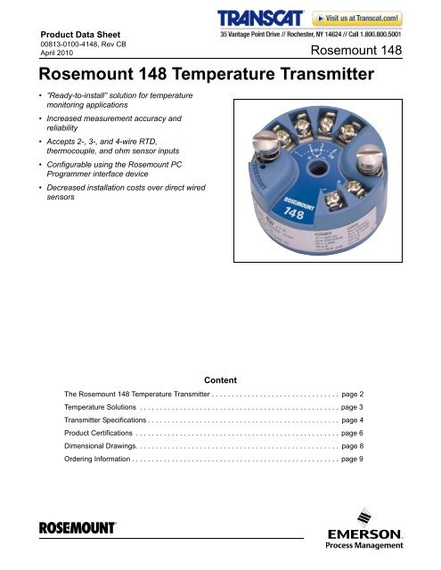
Product Data Sheet<br />
00813-0100-4<strong>148</strong>, Rev CB<br />
April 2010 <strong>Rosemount</strong> <strong>148</strong><br />
<strong>Rosemount</strong> <strong>148</strong> <strong>Temperature</strong> <strong>Transmitter</strong><br />
• ”Ready-to-install” solution for temperature<br />
monitoring applications<br />
• Increased measurement accuracy and<br />
reliability<br />
• Accepts 2-, 3-, and 4-wire RTD,<br />
thermocouple, and ohm sensor inputs<br />
• Configurable using the <strong>Rosemount</strong> PC<br />
Programmer interface device<br />
• Decreased installation costs over direct wired<br />
sensors<br />
Content<br />
The <strong>Rosemount</strong> <strong>148</strong> <strong>Temperature</strong> <strong>Transmitter</strong> . . . . . . . . . . . . . . . . . . . . . . . . . . . . . . . . page 2<br />
<strong>Temperature</strong> Solutions . . . . . . . . . . . . . . . . . . . . . . . . . . . . . . . . . . . . . . . . . . . . . . . . . . page 3<br />
<strong>Transmitter</strong> Specifications . . . . . . . . . . . . . . . . . . . . . . . . . . . . . . . . . . . . . . . . . . . . . . . . page 4<br />
Product Certifications . . . . . . . . . . . . . . . . . . . . . . . . . . . . . . . . . . . . . . . . . . . . . . . . . . . page 6<br />
Dimensional Drawings. . . . . . . . . . . . . . . . . . . . . . . . . . . . . . . . . . . . . . . . . . . . . . . . . . . page 8<br />
Ordering Information . . . . . . . . . . . . . . . . . . . . . . . . . . . . . . . . . . . . . . . . . . . . . . . . . . . . page 9<br />
www.rosemount.com
<strong>Rosemount</strong> <strong>148</strong><br />
Product Data Sheet<br />
00813-0100-4<strong>148</strong>, Rev CB<br />
April 2010<br />
The <strong>Rosemount</strong> <strong>148</strong> <strong>Temperature</strong> <strong>Transmitter</strong><br />
The <strong>Rosemount</strong> <strong>148</strong> is a low cost temperature<br />
transmitter used with multiple sensor type inputs in<br />
monitoring applications. The <strong>Rosemount</strong> <strong>148</strong> saves<br />
money in cabling and installation costs over wiring<br />
directly and delivers superior measurement accuracy<br />
and reliability.<br />
INSTALLATION READY SOLUTIONS<br />
The <strong>Rosemount</strong> <strong>148</strong> offers a complete point solution<br />
that guarantees the transmitter, housing, sensor,<br />
extension, and thermowell can be shipped from the<br />
factory as an installation-ready assembly.<br />
INCREASED PERFORMANCE<br />
The <strong>Rosemount</strong> <strong>148</strong> offers better measurement<br />
accuracy and improved reliability over wiring a<br />
temperature sensor directly back to the DCS.<br />
FLEXIBILITY<br />
The <strong>Rosemount</strong> <strong>148</strong> is compatible with 2-, 3-, and<br />
4-wire nickel and platinum RTDs, a variety of<br />
thermocouple sensors, and ohm inputs.<br />
LOW INSTALLED COST<br />
The <strong>Rosemount</strong> <strong>148</strong> reduces overall installation<br />
costs when compared to wiring sensors direct. In<br />
addition, the <strong>148</strong> can eliminate the use of expensive<br />
extension wires and multiplexers.<br />
PROGRAMMABLE<br />
The <strong>Rosemount</strong> <strong>148</strong> PC Programmer interface<br />
consists of a programmer, cables, and configuration<br />
software. The configuration software, when used in<br />
conjunction with the interface, provides the tools<br />
necessary to select the sensor type, sensor range,<br />
and sensor error action in addition to many other<br />
options.<br />
ROSEMOUNT TEMPERATURE SOLUTIONS<br />
<strong>Rosemount</strong> 3144P<br />
Field mount style HART ® or FOUNDATION fieldbus<br />
protocol. Dual sensor input with advanced<br />
diagnostics.<br />
<strong>Rosemount</strong> 644 Smart <strong>Temperature</strong> <strong>Transmitter</strong><br />
Head mount styles available with HART ® or<br />
FOUNDATION fieldbus protocol. Rail mount style<br />
available for HART protocol.<br />
<strong>Rosemount</strong> 848T High Density <strong>Temperature</strong><br />
Measurement Family<br />
Measure temperature points in close proximity with<br />
the 848T architecture, with WirelessHART or<br />
FOUNDATION fieldbus protocols.<br />
<strong>Rosemount</strong> 3420 Fieldbus Interface Module<br />
Provides an interface between FOUNDATION <br />
fieldbus instruments and systems without fieldbus<br />
capability using standard interface protocols.<br />
<strong>Rosemount</strong> 248 <strong>Temperature</strong> <strong>Transmitter</strong><br />
Head mount (DIN B) and Rail mount style with<br />
HART ® protocol.<br />
<strong>Rosemount</strong> sensors, thermowells, and<br />
extensions<br />
<strong>Rosemount</strong> has a broad offering of RTD and<br />
thermocouples that are designed to meet plant<br />
requirements.<br />
2
Product Data Sheet<br />
00813-0100-4<strong>148</strong>, Rev CB<br />
April 2010<br />
<strong>Rosemount</strong> <strong>148</strong><br />
<strong>Temperature</strong> Solutions<br />
SINGLE POINT MEASUREMENT<br />
Real Results<br />
<strong>Rosemount</strong> single point transmitters deliver<br />
exceptional results by utilizing innovative designs<br />
and advance diagnostics. A comprehensive and<br />
versatile portfolio provides solutions for single point<br />
measurement needs.<br />
Single Point. Single Provider.<br />
Every one of the 200,000+ temperature transmitters<br />
Emerson delivers each year possesses the quality<br />
and reliability that you expect from <strong>Rosemount</strong><br />
instrumentation.<br />
• Simplify installation with complete assemblies<br />
that are configured and calibrated to your<br />
specifications<br />
• Maximize process efficiency with<br />
industry-leading accuracy and stability<br />
• Optimize your limited resources with<br />
preventative maintenance diagnostics<br />
• Simplify safety compliance with SIS certified<br />
transmitters and prior-use safety<br />
documentation<br />
GLOBAL REACH. LOCAL SUPPORT.<br />
Worldwide Manufacturing<br />
With numerous <strong>Rosemount</strong> <strong>Temperature</strong><br />
manufacturing sites located worldwide and continued<br />
expansion of our operations, Emerson is ready to<br />
respond to all your project and daily needs. Our<br />
world-class manufacturing provides:<br />
• Globally consistent product from every factory<br />
• A single provider for transmitters, sensors and<br />
thermowells<br />
• Capacity to fulfill the needs of your largest<br />
projects<br />
• Overnight deliveries for emergency needs<br />
Local Expertise<br />
When you need a temperature expert, Emerson is<br />
there. Our experienced Instrumentation Consultants<br />
help you find the right product for your temperature<br />
application and advise you on best installation<br />
practices to ensure you see real results. With our<br />
extensive global network of service and support<br />
personnel, we can be on site to help when and where<br />
you need us.<br />
3
<strong>Rosemount</strong> <strong>148</strong><br />
<strong>Transmitter</strong> Specifications<br />
Product Data Sheet<br />
00813-0100-4<strong>148</strong>, Rev CB<br />
April 2010<br />
FUNCTIONAL SPECIFICATIONS<br />
Inputs<br />
User-selectable; sensor terminals rates to 42.4 V dc. See<br />
“<strong>Transmitter</strong> Accuracy and Ambient <strong>Temperature</strong> Effects” on<br />
page 4 for sensor options.<br />
Output<br />
2-wire 4–20 mA, linear with temperature or input.<br />
Isolation<br />
Input/Output isolation tested to 500V ac rms (707 V dc) at 50/60<br />
Hz.<br />
Supply Voltage DC<br />
Standard: 12 to 35 V<br />
Intrinsic Safety: 12 to 28 V<br />
Minimum Voltage Across Terminals<br />
12 V dc<br />
Humidity Limits<br />
0 - 95% relative humidity, non-condensing<br />
NAMUR Recommendations<br />
The <strong>148</strong> meets the following NAMUR recommendations:<br />
• NE 21 - Electromagnetic compatibility (EMC) for Process and<br />
Laboratory Apparatus<br />
• NE 43 - Standard of the signal level breakdown information of<br />
digital transmitters<br />
Transient Protection<br />
The optional rosemount 470 Transient Protector prevents damage<br />
from transients induced by lightning, welding, heavy electrical<br />
equipment, or switch gears. Refer to the 470 Product Data Sheet<br />
(document number 00813-0100-4191) for more information.<br />
<strong>Temperature</strong> Limits<br />
Operating Limit<br />
• -40 to 185 F (-40 to 85 C)<br />
Storage Limit<br />
• -58 to 248 F (-50 to 120 C)<br />
Turn-on Time<br />
Performance within specifications is less than 5.0 seconds after<br />
power is applied to the transmitter, when damping value is set to<br />
zero seconds.<br />
Update Rate<br />
Less than 0.5 seconds<br />
Damping<br />
32 seconds maximum, 5 seconds default.<br />
Recommended Minimum Measuring Span<br />
F (10 C)<br />
Software Detected Failure Mode<br />
The values at which the transmitter drives its output in failure<br />
mode depends on device configuration. The device can be<br />
configured to meet NAMUR-compliant (NAMUR recommendation<br />
NE 43) operation. The values for standard and NAMUR-compliant<br />
operation are as follows:<br />
TABLE 1. Operation Parameters<br />
NAMUR<br />
Standard (1)<br />
NE43-Complaint (1)<br />
Linear Output: 3.9 I 20.5 3.8 I 20.5<br />
Fail High: 21 I 23 (default) 21 I 23 (default)<br />
Fail Low: I 3.75 I 3.6<br />
(1) Measured in milliamperes<br />
Certain hardware failures, such as microprocessor failures, will<br />
always drive the output to greater than 23 mA.<br />
PERFORMANCE SPECIFICATIONS<br />
EMC (ElectroMagnetic Compatibility) NAMUR NE21<br />
Standard<br />
The <strong>148</strong> meets the requirements for NAMUR NE21 Rating<br />
Susceptibility Parameter Influence<br />
ESD<br />
• 6 kV contact discharge None<br />
• 8 kV air discharge<br />
Radiated • 80 – 1000 MHz at 10 V/m AM None<br />
Burst • 1 kV for I.O. None<br />
Surge<br />
• 0.5 kV line–line<br />
None<br />
• 1 kV line–ground (I.O. tool)<br />
Conducted • 150 kHz to 80 MHz at 10 V None<br />
CE Mark<br />
The <strong>148</strong> meets all of the requirements listed under IEC 61326:<br />
Amendment 1, 2006.<br />
Power Supply Effect<br />
Less than ±0.0055 of span per volt.<br />
Vibration Effect<br />
The <strong>148</strong> is tested to the following specifications with no effect on<br />
performance:<br />
Frequency<br />
Vibration<br />
10 to 60 Hz 0.21 mm displacement<br />
60 to 2000 Hz 3 g peak acceleration<br />
Stability<br />
For RTD and thermocouple inputs, the transmitter will have a<br />
stability of ±0.15% of reading or 0.15 C (whichever is greater) for<br />
twelve months.<br />
4
Product Data Sheet<br />
00813-0100-4<strong>148</strong>, Rev CB<br />
April 2010<br />
<strong>Rosemount</strong> <strong>148</strong><br />
Sensor Connections<br />
<strong>148</strong> Sensor Connections Diagram<br />
1 234 12 34 1234 1234<br />
2-wire<br />
RTD and <br />
3-wire<br />
*<br />
RTD<br />
and <br />
4-wire<br />
RTD<br />
and <br />
T/C<br />
* <strong>Rosemount</strong> Inc. provides 4-wire sensors for all single element RTDs. You can use these RTDs in 3-wire<br />
configurations by leaving the unneeded leads disconnected and insulated with electrical tape.<br />
<strong>Transmitter</strong> Accuracy and Ambient <strong>Temperature</strong> Effects<br />
NOTE<br />
The accuracy and ambient temperature effect is the greater of the fixed and percent of span values (see example below).<br />
TABLE 2. <strong>148</strong> <strong>Transmitter</strong> Input Options, Accuracy, and Ambient <strong>Temperature</strong> Effects<br />
Sensor <strong>Transmitter</strong> Input Ranges (1)<br />
(1) Input ranges are for transmitter only. Actual sensor (RTD or Thermocouple) operating ranges may be more limited. See<br />
“Sensor Specifications” on page 84 for temperature ranges.<br />
(2) Change in ambient is with reference to the calibration temperature of the transmitter at 68 °F (20 °C) from factory.<br />
(3) IEC 751, 1995<br />
(4) JIS 1604, 1981<br />
(5) Edison Curve No. 7<br />
(6) Edison Copper Winding No. 15<br />
(7) Total accuracy for thermocouple measurement: sum of accuracy +0.5 °C.<br />
(8) NIST Monograph 175, IEC 584<br />
(9) Fixed accuracy for NIST Type B is ±5.4 °F (±3.0 °C) from 212 to 572 °F (100 to 300 °C).<br />
(10) Fixed accuracy for NIST Type K is ±1.3 °F (±0.7 °C) from -292 to -130 °F (-130 to -90 °C).<br />
<strong>Transmitter</strong> Accuracy Example<br />
When using a Pt 100 (a = 0.00385) sensor input with a 0 to 100 °C span, use the greater of the two calculated values. In this case the accuracy<br />
would be +/-0.3 °C.<br />
<strong>Transmitter</strong> <strong>Temperature</strong> Effects Example<br />
<strong>Transmitter</strong>s can be installed in locations where the ambient temperature is between –40 and 85 °C (–40 and 185 °F). In order to maintain<br />
excellent accuracy performance, each transmitter is individually characterized over this ambient temperature range at the factory.<br />
When using a Pt 100 (a = 0.00385) sensor input with a 0–100 °C span at 30 °C ambient temperature:<br />
• <strong>Temperature</strong> Effects: 0.009 °C x (30 - 20) = 0.09 °C<br />
Total <strong>Transmitter</strong> Error<br />
Accuracy<br />
Worst Case <strong>Transmitter</strong> Error: Accuracy + <strong>Temperature</strong> Effects = 0.3 °C + 0.09 °C = 0.39 °C<br />
Total Probable <strong>Transmitter</strong> Error: 0.3 2 + 0.09 2 = 0.31C<br />
<strong>Temperature</strong> Effects per 1.0 °C (1.8 °F)<br />
Change in Ambient <strong>Temperature</strong> (2)()<br />
°C °F Fixed % of Span Fixed % of Span<br />
2-, 3-, 4-wire RTDs<br />
Pt 100 (3) ( = 0.00385) –200 to 850 –328 to 1562 0.3 °C (0.54 °F) ±0.15 0.009 °C (0.016 °F) ±0.006<br />
Pt 100 (4) ( = 0.003916) –200 to 645 –328 to 1193 0.3 °C (0.54 °F) ±0.15 0.009 °C (0.016 °F) ±0.006<br />
Ni 120 (5)<br />
–70 to 300 –94 to 572 0.2 °C (0.36 °F) ±0.15 0.006 °C (0.011 °F) ±0.006<br />
Cu 10 (6)<br />
–50 to 250 –58 to 482 3 °C (5.40 °F) ±0.15 0.09 °C (0.16 °F) ±0.006<br />
Thermocouples (7)<br />
(8) (9)<br />
Type B 100 to 1820 212 to 3308 2.3 °C (4.05 °F) ±0.15 0.084 °C (0.150 °F) ±0.006<br />
Type J (8) –180 to 760 –292 to 1400 0.8 °C (1.35 °F) ±0.15 0.03 °C (0.054 °F) ±0.006<br />
Type K (8) (10)<br />
–180 to 1372 –292 to 2502 0.8 °C (1.35 °F) ±0.15 0.03 °C (0.054 °F) ±0.006<br />
Type N (8) –200 to 1300 –328 to 2372 1.2 °C (2.16 °F) ±0.15 0.03 °C (0.054 °F) ±0.006<br />
Type R (8) 0 to 1768 32 to 3214 1.8 °C (3.24 °F) ±0.15 0.09 °C (0.16 °F) ±0.006<br />
Type S (8) 0 to 1768 32 to 3214 1.5 °C (2.70 °F) ±0.15 0.09 °C (0.16 °F) ±0.006<br />
2-, 3-, 4-wire Ohm Input 0 to 2000 ohms 1.1 ohm ±0.15 0.042 ohm ±0.009<br />
5
<strong>Rosemount</strong> <strong>148</strong><br />
Product Data Sheet<br />
00813-0100-4<strong>148</strong>, Rev CB<br />
April 2010<br />
Product Certifications<br />
APPROVED MANUFACTURING<br />
LOCATIONS<br />
<strong>Rosemount</strong> Inc. – Chanhassen, Minnesota, USA<br />
Emerson Process Management <strong>Temperature</strong> GmbH – Karlstein,<br />
Germany<br />
Emerson Process Management Asia Pacific – Singapore<br />
E5<br />
FM Explosion-Proof<br />
Explosion-Proof for Class I, Division 1, Groups B, C, and D.<br />
Dust Ignition Proof for Class II/III, Division 1, Groups E, F, G<br />
when installed in accordance with <strong>Rosemount</strong> drawing<br />
00<strong>148</strong>-1065.<br />
<strong>Temperature</strong> Code:<br />
T5 (T amb = –40 to 85 °C)<br />
EUROPEAN UNION DIRECTIVE<br />
INFORMATION<br />
The EC declaration of conformity for all applicable European<br />
directives for this product can be found on the <strong>Rosemount</strong> website<br />
at www.rosemount.com. A hard copy may be obtained by<br />
contacting your local sales representative.<br />
ATEX Directive (94/9/EC)<br />
<strong>Rosemount</strong> Inc. complies with the ATEX Directive.<br />
Electro Magnetic Compatibility (EMC)<br />
(89/336/EEC)<br />
All Models: EN 50081-1: 1992; EN 50082-2:1995;<br />
EN 61326-1. 2006<br />
CE Mark<br />
The <strong>148</strong> meets all requirements listed under<br />
IEC 61326:Amendment 1,2006<br />
HAZARDOUS LOCATIONS<br />
CERTIFICATIONS (1)<br />
North American Certifications<br />
Factory Mutual (FM)<br />
I5 FM Intrinsic Safety and Non-incendive<br />
Intrinsically Safe for Class I/II/III, Division 1, Groups A, B, C,<br />
D, E, F, and G. Non-incendive Field Circuit for Class I,<br />
Division 2, Groups A, B, C, and D. Intrinsically Safe and<br />
non-incendive when installed in accordance with<br />
<strong>Rosemount</strong> drawing 00<strong>148</strong>-1055.<br />
<strong>Temperature</strong> Codes:<br />
T5 (T amb = –50 to 75 °C)<br />
T6 (T amb = –50 to 40 °C)<br />
TABLE 3. Entity Parameters<br />
Loop/Power<br />
Sensor<br />
U i = 30 Vdc<br />
U o = 45 Vdc<br />
I i = 130 mA<br />
I o = 26 mA<br />
P i = 1.0 W<br />
P o = 290 mW<br />
C i = 3.6 nF<br />
C o = 0.4 nF<br />
L i = 13.8 H<br />
L o = 49.2 mH<br />
Combination Certifications<br />
K5 Combination of I5 and E5.<br />
Canadian Standards Association (CSA) Approvals<br />
I6 CSA Intrinsically Safe and Class I, Division 2<br />
Intrinsically Safe for Class I, Division 1, Groups A, B, C, and<br />
D when installed in accordance with <strong>Rosemount</strong> drawing<br />
00<strong>148</strong>-1056.<br />
<strong>Temperature</strong> Codes:<br />
T5 (T amb = –50 to 60 °C)<br />
T6 (T amb = –50 to 40 °C)<br />
Suitable for use in Class I, Division 2, Groups A, B, C, and D.<br />
K6 CSA Intrinsically Safe, Explosion-Proof, and Class I,<br />
Division 2.<br />
Combination of I6 and Explosion-Proof for Class I, Division<br />
1, Groups B, C, and D; Class II, Division 1, Groups E, F, and<br />
G; Class III, Division 1 hazardous locations, when installed<br />
in accordance with <strong>Rosemount</strong> drawing 00644-1059.<br />
Suitable for Class I, Division 2, Groups A,B, C, and D.<br />
Ambient <strong>Temperature</strong> Limit: –50 to 85°C<br />
European Certifications<br />
I1 ATEX Intrinsic Safety<br />
Certificate Number: Baseefa080ATEX0030X<br />
ATEX Marking: II 1 G<br />
1180<br />
EEx ia IIC<br />
<strong>Temperature</strong> Codes:<br />
T5 (–60 T amb 80 °C)<br />
T6 (–60 T amb 60 °C)<br />
TABLE 4. Entity Parameters<br />
Loop/Power<br />
Sensor<br />
U i = 30 Vdc<br />
U o = 45 Vdc<br />
I i = 130 mA<br />
I o = 26 mA<br />
P i = 1.0 W<br />
P o = 290 mW<br />
C i = 3.6 nF<br />
C i = 2.1 nF<br />
L i = 0 L i = 0<br />
Special Conditions for Safe Use (X):<br />
The apparatus must be installed in an enclosure which<br />
affords it a degree of protection of at least IP20.<br />
Non-metallic enclosures must have a surface resistance of<br />
less than 1 GOHM; light alloy or zirconium enclosures must<br />
be protected from impact and friction when installed.<br />
(1) Consult factory for availability.<br />
6
Product Data Sheet<br />
00813-0100-4<strong>148</strong>, Rev CB<br />
April 2010<br />
<strong>Rosemount</strong> <strong>148</strong><br />
E1<br />
N1<br />
NC<br />
ND<br />
ATEX Flame-Proof<br />
Certificate Number: KEMA99ATEX8715<br />
ATEX Marking: II 2 G<br />
1180<br />
EEx d IIC<br />
TABLE 5. Input Parameters<br />
U max = 42.4 Vdc<br />
I max = 24 mA<br />
<strong>Temperature</strong> Codes:<br />
T6 (–40 T amb 65 °C)<br />
ATEX Type n<br />
Certificate Number: BAS00ATEX3145<br />
ATEX Marking: II 3<br />
EEx nL IIC<br />
TABLE 6. Input Parameters<br />
U max = 45 V<br />
<strong>Temperature</strong> Codes:<br />
T5 (–40 T amb 70 °C)<br />
ATEX Type n Component<br />
Certificate Number: Baseefa08ATEX0031U<br />
ATEX Marking: II 3G<br />
EEx nA IIC<br />
TABLE 7. Input Parameters<br />
U i = 42.4 V<br />
C i = 3.6nF<br />
L i = 0<br />
<strong>Temperature</strong> Codes:<br />
T5 (–60 T amb 80°C)<br />
T6 (–60 T amb 60°C)<br />
ATEX Dust Ignition Proof<br />
Certificate Number: KEMA99ATEX8715<br />
ATEX Marking: II 1 D<br />
CE 1180<br />
T95 C (-40 T amb 85 °C)<br />
IP66<br />
TABLE 8. Input Parameters<br />
U max = 42.4 Vdc<br />
I max = 24 mA<br />
Australian Certifications<br />
Standard Australia Quality Assurance Service<br />
(SAA) Approvals<br />
E7<br />
SAA Explosion-Proof<br />
Certificate Number: AUSEx3716X<br />
Ex d IIC<br />
<strong>Temperature</strong> Codes:<br />
T6 (–40 T amb 65 °C)<br />
Special Conditions for Safe Use (X):<br />
1. A thermowell must be utilized on installations<br />
incorporating a DIN style or a spring loaded sensor<br />
assembly, with all threaded connections sealed with<br />
sealing tape to maintain the IP rating of IP66/IP68 (3<br />
meters).<br />
2. When a gland is utilized on installation, the gland must be<br />
Standards Australia certified and must be capable of<br />
maintaining the IP rating. This also requires the use of<br />
thread sealing tape on all gland entries.<br />
Brazilian Certifications<br />
Centro de Pesquisas de Energia Eletrica<br />
(CEPEL) Approval<br />
I2<br />
CEPEL Intrinsic Safety<br />
IECEx Certifications<br />
I7 IECEx Intrinsic Safety (Zone 0)<br />
Certificate Number: IECExBAS08.0011X<br />
EEx ia nL IIC|<br />
<strong>Temperature</strong> Codes:<br />
T5 (-60 °C to 80°C)<br />
T6 (-60 °C to 60°C)(<br />
TABLE 9. Entity Parameters<br />
Ex ia Terminals ±<br />
U i = 30 Vdc<br />
I i = 130 mA<br />
P i = 1.0 W<br />
C i = 3.63 nF<br />
L i = 0 mH<br />
Conditions of Certification:<br />
1. It is a condition of safe use that the input entity<br />
parameters must be taken into account when connecting<br />
to a supply. For sensor output terminals, the sensor entity<br />
parameters shall be taken into account during installation.<br />
2. It is a condition of safe use that the apparatus shall only<br />
be supplied from a galvanically isolated safety barrier with<br />
output current limited by a minimum 225 Ohms resistor.<br />
3. It is a condition of safe use that the transmitter must be<br />
mounted in an enclosure that suits Group IIC application<br />
and affords a degree of protection of at least IP20 for Ex ia<br />
version, and of at least IP54 for Ex n version.<br />
4. It is a condition of safe use that the apparatus shall be<br />
installed according to the installation drawing 00<strong>148</strong>-1057.<br />
N7 IECEx Type n (Zone 2)<br />
Certificate Number: IECExBAS07.0055<br />
Ex nA NL IIC<br />
<strong>Temperature</strong> Codes:<br />
T5 (T amb = -40 °C to 75 °C))<br />
TABLE 10. Ex n Input Parameters<br />
Ex n Terminals ±<br />
U i = 45 V<br />
NG<br />
Sensor<br />
U o = 45 Vdc<br />
I o = 26 mA<br />
P o = 290 mW<br />
C i = 2.1 nF<br />
L i = 0 mH<br />
IECEx Type n Component<br />
Certificate number: IECExBAS08.0012U<br />
Ex na IIC<br />
<strong>Temperature</strong> Codes<br />
T5 (T amb = -60 °C to 75 °C)<br />
T6(T amb = -60 °C to 60 °C)<br />
TABLE 11. Input Parameters<br />
U i = 42.4 V<br />
C i = 3.6nF (4–20 mA loop)<br />
C i = 2.1nF (<strong>Temperature</strong> Sensor Input)<br />
L i = 0<br />
7
<strong>Rosemount</strong> <strong>148</strong><br />
Product Data Sheet<br />
00813-0100-4<strong>148</strong>, Rev CB<br />
April 2010<br />
Dimensional Drawings<br />
<strong>Rosemount</strong> <strong>148</strong> Top View<br />
<strong>Rosemount</strong> <strong>148</strong> Side View<br />
12.9 (0.51)<br />
33 (1.3)<br />
24.5 (0.97)<br />
44 (1.7)<br />
Dimensions are in millimeters (inches)<br />
DIN Rail Mounting Kit<br />
Dimensions<br />
50 (1.97)<br />
Dimensions are in millimeters (inches)<br />
8
Product Data Sheet<br />
00813-0100-4<strong>148</strong>, Rev CB<br />
April 2010<br />
Ordering Information<br />
<strong>Rosemount</strong> <strong>148</strong><br />
TABLE 12. <strong>Rosemount</strong> <strong>148</strong> PC-Programmable <strong>Temperature</strong> <strong>Transmitter</strong><br />
★ The Standard offering represents the most common options. The starred options (★) should be selected for best delivery.<br />
__The Expanded offering is subject to additional delivery lead time.<br />
Model Product Description<br />
<strong>148</strong> PC Programmable <strong>Temperature</strong> <strong>Transmitter</strong><br />
<strong>Transmitter</strong> Type<br />
Standard<br />
Standard<br />
H DIN B Head Mount ★<br />
<strong>Transmitter</strong> Output<br />
Standard<br />
Standard<br />
N Analog Output ★<br />
Product Certifications<br />
Standard<br />
Standard<br />
I5 FM Intrinsic Safety and Class 1, Division 2 ★<br />
E5 (1) FM Explosion-Proof ★<br />
K5 (1) FM Intrinsic Safety, Explosion-Proof, and Class 1, Division 2 ★<br />
I6 CSA Intrinsic Safety and Class 1, Division 2 ★<br />
K6 (1) CSA Intrinsic Safety, Explosion-Proof, and Class 1, Division 2 ★<br />
I1 ATEX Intrinsic Safety ★<br />
E1 (1) ATEX Flameproof ★<br />
N1 (1) ATEX Type n ★<br />
NC ATEX Type n Component ★<br />
ND (1) ATEX Dust Ignition-Proof ★<br />
I7 IECEx Intrinsic Safety ★<br />
E7 (1) IECEx Flameproof ★<br />
N7 (1) IECEx Type N ★<br />
NG IECEx Type n Component ★<br />
NA No approvals ★<br />
Enclosure Options Material IP Rating<br />
Standard<br />
Standard<br />
A Connection Head Aluminum IP68 ★<br />
U Universal Head (Junction Box) Aluminum IP68 ★<br />
B BUZ Head Aluminum IP65 ★<br />
C BUZ Head Polypropylene IP65 ★<br />
N No Enclosure ★<br />
Expanded<br />
G Connection Head SST IP68<br />
H Universal Head (Junction Box) SST IP68<br />
S Sanitary Connection Head, DIN B Polished SST IP66<br />
F Sanitary Connection Head, DIN A Polished SST IP66/IP68<br />
Conduit Entry Size<br />
Standard<br />
Standard<br />
1 M20 x 1.5 (CM20) ★<br />
2<br />
1 /2-14 in. NPT ★<br />
0 No Enclosure ★<br />
Options (Include with selected model number)<br />
Alarm Level Configuration<br />
Standard<br />
Standard<br />
A1 NAMUR alarm and saturation levels, high alarm ★<br />
CN NAMUR alarm and saturation levels, low alarm ★<br />
9
<strong>Rosemount</strong> <strong>148</strong><br />
Product Data Sheet<br />
00813-0100-4<strong>148</strong>, Rev CB<br />
April 2010<br />
TABLE 12. <strong>Rosemount</strong> <strong>148</strong> PC-Programmable <strong>Temperature</strong> <strong>Transmitter</strong><br />
★ The Standard offering represents the most common options. The starred options (★) should be selected for best delivery.<br />
__The Expanded offering is subject to additional delivery lead time.<br />
Calibration Certificate<br />
Standard<br />
Q4 Calibration Certificate (3-point Calibration) ★<br />
Line Filter<br />
Standard<br />
F6 60 Hz Line Voltage Filter ★<br />
External Ground Option (Available w/Enclosures U, H)<br />
Standard<br />
G1 External Ground Lug Assembly ★<br />
Cover Chain Option (Available w/Enclosures U, H)<br />
Standard<br />
G3 Cover Chain ★<br />
Cable Glande Option<br />
Standard<br />
G2 Cable Gland–Explosion Proof–7.5 mm - 11.9 mm ★<br />
G4 Cable Gland–Explosion Proof, Thin Wire - 3.0 mm - 8.0 mm ★<br />
Conduit Electrical Connector<br />
Standard<br />
GE M12, 4-pin, Male Connector (eurofast ® ) ★<br />
GM A size Mini, 4-pin, Male Connector (minifast ® ) ★<br />
Assemble To Options<br />
Standard<br />
XA Sensor Specified Separately and Assembled to <strong>Transmitter</strong> ★<br />
Typical Model Number:<br />
<strong>148</strong> H N I5 U1 A1 XA<br />
(1) Approval Codes E1, N1, N7, ND, E5, K5, K6, and E7 require an enclosure<br />
Standard<br />
Standard<br />
Standard<br />
Standard<br />
Standard<br />
Standard<br />
Standard<br />
10
Product Data Sheet<br />
00813-0100-4<strong>148</strong>, Rev CB<br />
April 2010<br />
<strong>Rosemount</strong> <strong>148</strong><br />
<strong>Rosemount</strong> <strong>148</strong> PC Programmer<br />
The <strong>Rosemount</strong> <strong>148</strong> PC Programmer is a portable, self-contained<br />
communication link between your PC and the <strong>148</strong> transmitter for<br />
use in non-hazardous environments. The <strong>148</strong> PC Programmer<br />
contains the following items:<br />
• PC Programmer Unit<br />
• Programming Software (CD-ROM)<br />
• 9V Battery<br />
• <strong>Transmitter</strong> Connectors<br />
<strong>Rosemount</strong> <strong>148</strong> PC Programmer Software<br />
The software makes the following parameters available:<br />
• Process Variable<br />
• Sensor Type<br />
• Number of Wires<br />
• Engineering Units<br />
• <strong>Transmitter</strong> Tag Information)<br />
• Damping<br />
• Alarming Parameters<br />
To order the <strong>148</strong> PC Programmer, use Part Number<br />
00<strong>148</strong>-1601-0001.<br />
TABLE 13. <strong>Rosemount</strong> <strong>148</strong> <strong>Transmitter</strong> Accessories<br />
External Ground Screw Assembly Kit 00644-4431-0001<br />
Mounting Kit, Hardware for Mounting a <strong>148</strong> to a DIN Rail (see left picture-top hat rail, symmetric) 00248-1601-0001<br />
Hardware<br />
Snap Rings Kit (used for assembly to DIN Plate Style sensor) 00644-4432-0001<br />
<strong>Transmitter</strong><br />
Rail Clip<br />
11
<strong>Rosemount</strong> <strong>148</strong><br />
Product Data Sheet<br />
00813-0100-4<strong>148</strong>, Rev CB<br />
April 2010<br />
The Emerson logo is a trademark and service mark of Emerson Electric Co.<br />
<strong>Rosemount</strong> and the <strong>Rosemount</strong> logotype are registered trademarks of <strong>Rosemount</strong> Inc.<br />
PlantWeb is a registered trademark of one of the Emerson Process Management group of companies.<br />
Eurofast and Minifast are registered trademarks of Turck Inc.<br />
All other marks are the property of their respective owners.<br />
Standard Terms and Conditions of Sale can be found at www.rosemount.com\terms_of_sale<br />
© 2010 <strong>Rosemount</strong> Inc. All rights reserved<br />
Emerson Process Management<br />
<strong>Rosemount</strong> Inc.<br />
8200 Market Boulevard<br />
Chanhassen, MN 55317 USA<br />
T (U.S.) 1-800-999-9307<br />
T (International) (952) 906-8888<br />
F (952) 949-7001<br />
Emerson Process Management<br />
Blegistrasse 23<br />
P.O. Box 1046<br />
CH 6341 Baar<br />
Switzerland<br />
T +41 (0) 41 768 6111<br />
F +41 (0) 41 768 6300<br />
Emerson FZE<br />
P.O. Box 17033<br />
Jebel Ali Free Zone<br />
Dubai UAE<br />
T +971 4 883 5235<br />
F +971 4 883 5312<br />
Emerson Process ManagementAsia<br />
Pacific Pte Ltd<br />
1 Pandan Crescent<br />
Signapore 128461<br />
T +65 6777 8211<br />
F +65 6777 0947<br />
Service Support Hotline: +65 6770 8711<br />
Email: Enquiries@AP.EmersonProcess.com<br />
www.rosemount.com<br />
© 00813-0100-4<strong>148</strong> Rev CB 4/10