Instruction Manual
Instruction Manual
Instruction Manual

You also want an ePaper? Increase the reach of your titles
YUMPU automatically turns print PDFs into web optimized ePapers that Google loves.
Introduction<br />
Congratulations on your decision to mount your TV with a TV Wall Mounting Kit For<br />
Dummies. The enclosed mounting bracket was engineered and designed by Bell’O<br />
International Corporation using the latest computer-aided design and stress-analysis<br />
software to ensure safety and durability when installed according to the instructions. It<br />
has been further tested and Listed by Underwriters Laboratories.<br />
About This <strong>Manual</strong><br />
Mounting your TV on the wall can seem like an overwhelming task. This handy For Dummies ®<br />
guide takes you through the process step-by-step to ensure the proper installation of your<br />
mount. Before starting this project, be sure to read the entire instruction manual and watch the<br />
included installation DVD for a complete demonstration. If at any time you are unclear about<br />
the directions and believe you need further assistance, contact the Bell’O ® installation experts<br />
at 888-779-7781 from 9am – 5pm EST.<br />
Icons Used in This Book<br />
Don’t be alarmed by the bomb in the icon. We just want to<br />
get your attention because making an error could be costly.<br />
This is not really very technical stuff, just some details you<br />
need to really pay attention to.<br />
Foolish Assumptions<br />
Although our easy-to-install mounts and instructions simplify the process, mounting your<br />
TV still requires great care. We assume you’re someone who, at minimum, has done odd<br />
jobs around the house and has some basic tools. You don’t need to be a master carpenter or<br />
electrician to install this mount. With that said, if at any time you feel that you are<br />
uncertain or uncomfortable with doing the installation yourself, don’t hesitate to call on a<br />
handyman or professional contractor/installer.<br />
English
Precautions!<br />
• This mounting bracket was designed to be installed and utilized ONLY<br />
as specified in this manual. Bell’O International Corporation will not<br />
be responsible for failure to assemble as directed or for the improper<br />
assembly, use, or handling of this product.<br />
• Improper installation of this product may cause damage or serious<br />
injury. Bell'O International Corporation cannot be liable for direct or<br />
indirect damage or injury caused by incorrect mounting, incorrect<br />
use, or incorrect assembly.<br />
• If the mounting bracket will be attached to any structure other than<br />
those specified in this manual, only a licensed professional<br />
contractor/installer should perform this installation. The supporting<br />
structure must support, at minimum, four times the combined weight<br />
of the mounting bracket and TV. It is the responsibility and liability of<br />
the installer to ensure the suitability of the supporting structure.<br />
• This product should NEVER be mounted to metal framing studs.<br />
• Check carefully to ensure that there are no missing or damaged parts.<br />
Never use defective parts. If any parts are damaged or missing, call<br />
Bell'O International Corporation at 888-779-7781 and parts will be<br />
shipped directly to purchaser. Please contact Bell’O International Corp.<br />
before attempting to return products to the point of purchase.<br />
• Specifications are subject to change without notice.<br />
• The maximum weight of your television cannot exceed the maximum<br />
weight rating of your mount or any attached Bell'O ® UL listed adapters<br />
sold separately, whichever is lower.<br />
NEVER exceed the maximum load capacity of:<br />
Mount 8315: 200 lbs (91 kg)<br />
Mount 8325: 200 lbs (91 kg)<br />
English
711 Ginesi Drive<br />
Wiley, the Wiley logo, For Dummies,<br />
the Dummies Man logo, and<br />
related trademarks o registered<br />
trademarks of John Wiley & Sons, Inc.<br />
and/or its a filiates. Used by license.<br />
Parts Included in This Kit<br />
(WP) 8315 or 8325 Wall Plate (8325 Shown), Quantity: 1<br />
Quite possibly the world’s<br />
easiest mounts to install!<br />
Installation Guide for<br />
TV Wall Mounting Kit<br />
For 8315 Mounting Bracket<br />
Installation Video for<br />
Bell’O TV Wall Mounting Kits<br />
A step-by-step guide for<br />
mounting your flat panel<br />
TV safely and easily!<br />
Video: 701<br />
© January 2007 Bell'O International Corporation. Contents of thisdiscarecopyrightedandarenotforreproductionordistributionwithoutwrittenpermissionfromBell’OInternationalCorp.AlldesignsandimagesarepropertyofBell’OInternationalCorp.Alldesignsarepatentedorpatentpending,andaresubjecttochangewithoutnotice.<br />
Be l’O International Corp.<br />
Morganvi le, NJ 07751<br />
English Français Español<br />
A step-by-step guide for<br />
mounting your flat panel<br />
TV safely and easily!<br />
(IG) Installation Guide<br />
& DVD, Quantity: 1 each<br />
(MA) Monitor Arms,<br />
Quantity: 2<br />
(EC) End Covers,<br />
Quantity: 2<br />
(IT) Installation Template,<br />
Quantity: 1<br />
TOGGLER ® brand ALLIGATOR ® SOLID-WALL ANCHORS are<br />
patented under one or more of US Patent numbers 5,161,296 and<br />
5,938,385; and foreign counterparts thereof and of 4,752,170.<br />
Other patents pending. TOGGLER and ALLIGATOR are worldwide<br />
registered trademarks of Mechanical Plastics Corporation.<br />
(U) TOGGLER ® brand<br />
AF8 ALLIGATOR ® Anchor, Quantity: 4<br />
English
Parts Included in This Kit (continued)<br />
(AB) M4 x 10mm Security Screw,<br />
Quantity: 2<br />
(A) M4 x 12mm Screw,<br />
Quantity: 4<br />
(B) M4 x 22mm Screw,<br />
Quantity: 4<br />
(C) M4 x 30mm Screw,<br />
Quantity: 4<br />
(M) M8 x 20mm Screw,<br />
Quantity: 4<br />
(N) M8 x 30mm Screw,<br />
Quantity: 4<br />
(O) M8 x 40mm Screw,<br />
Quantity: 4<br />
(G) M5 x 12mm Screw,<br />
Quantity: 4<br />
(H) M5 x 22mm Screw,<br />
Quantity: 4<br />
(I) M5 x 30mm Screw,<br />
Quantity: 4<br />
(J) M6 x 14mm Screw,<br />
Quantity: 4<br />
(K) M6 x 25mm Screw,<br />
Quantity: 4<br />
(L) M6 x 35mm Screw,<br />
Quantity: 4<br />
(T) #14 x 64mm Lag Bolt,<br />
Quantity: 4<br />
English
Parts Included in This Kit (continued)<br />
(D) M4/M5 Short<br />
Spacer, Quantity: 4<br />
(E) M4/M5 Long<br />
Spacer, Quantity: 4<br />
(R) M4/M5 Washer,<br />
Quantity: 4<br />
(Q) M6/M8 Short<br />
Spacer, Quantity: 4<br />
(P) M6/M8 Long<br />
Spacer, Quantity: 4<br />
(S) M6/M8 Washer,<br />
Quantity: 4<br />
Tools You Will Need<br />
Screwdriver Stud Finder Drill Drill Bit Pencil<br />
For wood 5/32" (4mm)<br />
For masonry 5/16" (8mm)<br />
Metric Ratchet<br />
Set (Optional)<br />
Masking Tape Tape Measure Level<br />
English
Getting ready to hang the TV<br />
Select the location where you want to mount the TV. Clear the area of all furniture and<br />
electronics. You will need some elbow room to mount the TV. You also want to make sure<br />
that your electronic devices are unplugged, covered, and out of way because you are about<br />
to start drilling holes, and that is likely to make dust. You will also need to leave space that<br />
you can use to mount the Monitor Arms (MA) onto the TV.<br />
Your TV may have come with a stand installed. If it did, it is okay to leave it on for<br />
now as long as it does not interfere with the monitor arm installation. If not, you need<br />
to determine the best way to hold or rest your TV safely so you can attach the<br />
monitor arms. Placing the TV face-down can damage the fragile screen or decorative<br />
frame. You may want to get a friend to assist you in holding the TV. If you are<br />
uncertain of the safest way to do this, call the TV manufacturer for advice.<br />
Step 1: Attaching the Adjustable Arms<br />
Your TV owner’s manual generally explains where the mounting location is on the<br />
TV. There are several typical mounting configurations for this size bracket. The<br />
mounting hole distances are measured in millimeters per the VESA (Video<br />
Electronics Standards Association) specifications.<br />
Who is VESA?<br />
The Video Electronics Standards Association is an international nonprofit organization<br />
representing hardware, software, PC, display, and component manufacturers, cable and<br />
telephone companies, and service providers. VESA supports and sets industry-wide<br />
interface standards for the PC, workstation, and computing environments.<br />
Choosing which screws to use for your TV<br />
You’re probably wondering why so many screws came with this mount. The screw sizes<br />
follow the standards setup by VESA for each mounting configuration.<br />
Most monitors have the mounting holes flush with the back of the monitor. If yours is<br />
like this, you likely need to use short screws. Test several of the screws included in this<br />
kit to find the correct match for the holes in the back of your TV.<br />
Don’t use screws that are too long because they will not fully seat in the holes<br />
and can permanently damage the TV or mounting holes and cause the monitor<br />
to come loose.<br />
English
Attaching the Monitor Arms<br />
After you’ve figured out which screws to use for your TV, attach each Monitor Arm<br />
(MA) to the back of the TV as shown in Figures 1 and 2. Make sure the the arms are<br />
oriented properly, with the adjustment levers facing toward the outer edge of the TV so<br />
you can reach them later.<br />
Also make sure that each Washer (R for M4 or M5 screws, or S for M6 or M8 screws)<br />
is placed between the screw and the monitor arm. Don’t place the washers between the<br />
arms and the TV.<br />
Figure 1<br />
DETAILED VIEW<br />
MA<br />
Back of TV<br />
R or S<br />
Selected<br />
Screw<br />
Adjustment Lever<br />
English
Some TVs have mounting holes that are recessed. This kit includes longer mounting<br />
screws and Spacers (D or E for M4 and M5 screws; P or Q for M6 and M8 screws) for<br />
such instances. The spacers are used to take up the space in the recessed hole as shown in<br />
Figure 2. The spacer you select must stick out past the back of the TV to ensure secure<br />
mounting. You don’t want the spacer to be loose. The Monitor Arms (MA) need to rest<br />
securely on the spacers. Test several of the spacers included in this kit to find the<br />
correct match for the recessed holes in the back of your TV.<br />
Figure 2<br />
DETAILED VIEW<br />
Selected Spacer<br />
MA<br />
R or S<br />
Selected Long Screw<br />
Back of TV<br />
Step 2: Securing the Wall Plate<br />
Finding the wood studs to mount to<br />
Using a stud finder, determine the exact<br />
location of the studs to which you want to<br />
attach the Wall Plate (WP). Using an<br />
electronic stud finder works best because it<br />
gives you an indication of where the right and<br />
left sides of the stud are. After you determine<br />
the stud locations, mark the right and left sides<br />
of each stud as shown in Figure 3. These<br />
markings help you determine the center location<br />
of each stud for proper drilling.<br />
Wood<br />
Stud<br />
Figure 3<br />
English
Determining the location of the TV<br />
After the Monitor Arms (MA) have been attached to the TV, measure the distance from<br />
the center of the monitor arms to the top and bottom of the TV to help determine the<br />
desired height of the TV on your wall. The reason that you need to take these<br />
measurements is because many TVs do not have the mounting location centered on the<br />
back of the monitor. To determine the exact height you want to mount the brackets, use<br />
the convenient Installation Template (IT) rather than holding the TV in place while you<br />
do all this measuring. Always make sure to use a level when placing the template. Measure<br />
from the floor up as shown in Figure 4, and using a pencil, make small marks on the wall to<br />
help you determine the desired TV height.<br />
Figure 4<br />
Desired Location of TV<br />
Level<br />
IT<br />
Distance from<br />
Bottom of TV<br />
to Center of<br />
Monitor Arms<br />
16<br />
Inches<br />
(406mm)<br />
Height to bottom of TV<br />
Wood<br />
Studs<br />
English
Using the Installation Template<br />
The Installation Template (IT) included in this kit helps you select the correct<br />
positions for drilling the holes for the TV mounting.<br />
Figure 5<br />
Lines for Locating Stud Markings<br />
Line up the installation template with your stud markings to ensure the proper location for<br />
your drill holes. After you have the position selected, tape the template in place securely<br />
on the wall with masking tape so that you don’t damage the wall surface. Use a level to<br />
double check that the screw holes will line up vertically. Drill four evenly spaced holes<br />
2.5" (64mm) deep using a 5/32" (or 4mm) size drill bit. Follow the directions on the<br />
installation template carefully.<br />
You must be careful to accurately drill the holes or else the screws may<br />
not line up with the holes in your Wall Plate (WP).<br />
Installing the Security Screw<br />
WP<br />
DETAILED VIEW<br />
Before you attach the Wall<br />
Plate (WP) to the wall, you<br />
need to insert the M4 x<br />
10mm Security Screws (AB)<br />
into the locking mechanism<br />
on each end of the bracket.<br />
Insert them only half-way,<br />
so that the locking arm can<br />
still be easily rotated.<br />
AB<br />
Figure 6<br />
English
When mounting to a wood stud<br />
When you have prepared the holes for mounting the Wall Plate (WP), place the plate<br />
over the holes and screw in the Lag Bolts (T), as shown in Figure 7. Leave some “wiggle”<br />
room so that you can make any fine adjustments, if necessary. After making sure the wall<br />
mount is level, tighten all of the lag bolts completely.<br />
Figure 7<br />
WP<br />
Supporting<br />
Stud<br />
Wall<br />
Supporting<br />
Stud<br />
T<br />
Tighten the Lag Bolts (T) so that the Wall Plate (WP) is firmly attached to the<br />
wall, but don’t over-tighten! The lag bolts and/or the supporting surface can<br />
become damaged, which greatly reduces their holding ability. Final tightening of<br />
the bolts should always be done by hand, with a Phillips-head screwdriver or<br />
ratchet wrench.<br />
English
When mounting to solid concrete, bricks, or cinder block<br />
After you have determined your desired TV location, tape the Installation Template (IT)<br />
in place securely on the wall with masking tape.<br />
Use a level to double check that the screw holes line up vertically, as shown in Figure 8.<br />
Figure 8<br />
Level<br />
IT<br />
Concrete Block Wall<br />
Do not drill into mortar joints! Mortar joints are in between the bricks where the<br />
cement is. These joints are typically not strong enough to hold heavy loads.<br />
You need to drill the holes at least one inch from the joint to provide adequate<br />
strength. Use a standard drill with a new masonry drill bit to drill the holes. Do<br />
not use a hammer drill because it can damage the hole or break out the back of<br />
the concrete wall which will not give adequate support to the anchor.<br />
Because drilling an accurate and clean hole is essential to securing your<br />
mount, be sure to use a new drill bit. An old drill bit can not only make<br />
an uneven hole, it can also break out the back of the concrete block<br />
which can diminish the holding ability of the anchor.<br />
Line up the installation template to ensure you’re not going to drill into any mortar<br />
joints. Drill four evenly spaced holes 3" (76mm) deep using a 5/16" (or 8mm) size drill bit.<br />
Follow the directions on the installation template carefully.<br />
English
This kit includes the TOGGLER ® brand ALLIGATOR ® Anchors (U) for mounting in<br />
concrete walls, brick, or cinder block. These patented anchors are the finest solid wall<br />
anchors on the market and offer excellent holding ability when properly installed.<br />
After the holes are drilled,<br />
remove the template and<br />
place four ALLIGATOR ®<br />
Anchors into the concrete<br />
wall as shown in Figure 9.<br />
Figure 9<br />
U<br />
After you have prepared the holes for mounting the Wall Plate (WP), install the wall plate<br />
by inserting the four Lag Bolts (T) through the mount and into the ALLIGATOR ®<br />
Anchors (U) as shown in Figures 7 and 10. After checking that the wall plate is level,<br />
tighten all lag bolts fully, but be careful not to over-tighten.<br />
Figure 10<br />
T<br />
3" (76mm)<br />
minimum hole depth<br />
WP<br />
U<br />
Concrete<br />
Installing the decorative End Covers<br />
Even though your TV hides most of your<br />
wall mount from view, from the sides you<br />
can probably still see the ends of the<br />
bracket. This kit includes decorative End<br />
Covers (EC) to make your bracket<br />
installation look clean and finished. To<br />
install the end covers, simply line up the<br />
cover with the end of the bracket, and<br />
press into place. Look for two holes in the<br />
frame of the bracket, which the end cover<br />
inserts into, as shown in Figure 11.<br />
EC<br />
Figure 11<br />
WP<br />
English
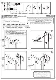
Step 3: Mounting the TV<br />
Understanding the locking mechanism<br />
Your TV Wall Mounting Kit For Dummies has a unique feature which enables you to<br />
easily lock the Monitor Arms (MA) onto the Wall Plate (WP) so that your TV cannot<br />
be removed. Before attempting to attach the TV with the monitor arms to the wall bracket,<br />
make sure that the right and left side locking mechanisms are in the unlocked position. Using a<br />
screwdriver, turn the large screw head on the side of the bracket 90° toward the front of<br />
the bracket, as shown in Figure 12.<br />
Figure 12<br />
To Unlock<br />
Large Screw<br />
Head<br />
Locking Bar<br />
Shown Up in<br />
Unlocked Position<br />
Don’t forget those wires!<br />
If your audio, video, and power cables will not be accessible after you mount<br />
the TV, you need to make those connections now. Before doing this, however,<br />
make sure all TV and component power cords are not plugged into any<br />
electrical outlets and your audio and video equipment is turned off. Make sure<br />
you leave enough slack so you can install the mount without any interference.<br />
English
Mounting the TV<br />
Before you attempt to attach the TV to the wall plate, make sure the adjustable arms are<br />
parallel to the TV (in the 0-degree position). This position is indicated by the markings<br />
on the arms as shown in Figure 13B. Detailed instructions on how to adjust the arms<br />
can be found on page 17.<br />
Figure 13A<br />
When you’re ready to put the TV<br />
with the Monitor Arms (MA) onto<br />
the Wall Plate (WP) assembly, get a<br />
friend or an assistant to help you lift<br />
the TV and guide the monitor arms<br />
onto the wall plate as shown in<br />
Figure 13A.<br />
MA<br />
DETAILED VIEW<br />
WP<br />
Figure 13B<br />
Markings on the adjustable arm will line up<br />
when in the 0-degree position.<br />
Make sure the arms are engaged on both the top and bottom rails of the wall plate!<br />
English
Locking the arms into place<br />
After the TV with the Monitor Arms (MA) is positioned on the Wall Plate (WP), you<br />
need to lock the arms into place so that the TV cannot inadvertently come off the wall<br />
plate or be removed. To lock the arms, simply turn the large screw head on the side of<br />
both of the bracket’s locking mechanisms 90° toward the wall using a screwdriver as<br />
your assistant holds the TV in place. (See Figure 14.) After you've done this, and the<br />
locking mechanism has been engaged, tighten the M4 x 10mm Security Screw (AB)<br />
behind the large lock screw to prevent the locking bar from rotating out of the locked<br />
position. Repeat this procedure on both sides of the bracket. For extra security, in<br />
addition to the security screw, you can also place a padlock through the large holes in<br />
the protruding tabs of the locking mechanism.<br />
Figure 14<br />
AB<br />
To Lock<br />
Large Screw<br />
Head<br />
Locking Bar<br />
Shown Down in<br />
Locked Position<br />
After the TV is installed, carefully try to lift it off to make sure it is secure.<br />
If it is correctly secured, the TV should not move.<br />
English
Using the tilting arm feature<br />
After you’ve securely locked the TV with the monitor arms securely onto the wall plate,<br />
you can safely adjust the tilting feature on the arms. The arms can tilt up to 15° downward<br />
or up to 5° upward, depending on your optimum viewing position. Have your assistant hold<br />
the TV steady before you start to adjust the tilt. To adjust the tilt of your TV, simply reach<br />
behind the TV and turn the lever in the center of the arm to loosen. It works like a ratchet<br />
so that you can loosen the lever easily in a very confined area. To disengage the lever, rotate<br />
it away from the monitor arm and reposition as shown in Figure 16. Push it in again to turn<br />
and adjust the arm’s tension as shown in Figure 15. Repeat this procedure for the lever on<br />
the other arm also before attempting to position the TV.<br />
After the TV is in the desired tilted position, you need to tighten the levers. Turn the levers<br />
clockwise to tighten, pulling out to disengage the rachet mechanism.<br />
Figure 15<br />
Push In to<br />
Turn Lever<br />
Pull Out to<br />
Disengage Lever<br />
Figure 16<br />
Turn<br />
Counter-<br />
Clockwise<br />
to Loosen<br />
Turn<br />
Clockwise<br />
to Tighten<br />
If you need to remove the TV<br />
Flat screen TVs are very heavy and extremely fragile. Exercise caution when<br />
removing the display from the mount to avoid equipment damage or personal injury.<br />
If your cables are accessible, disconnect all power and A/V cables before removing the<br />
TV with the Monitor Arms (MA) from the Wall Plate (WP). If cables are not<br />
accessible, have an assistant remove the cables as soon as the TV is lifted off the mount.<br />
Have an assistant hold the TV in place as you unlock the locking mechanism as<br />
described in Figure 12. After the locking mechanism has been disengaged fully, you can<br />
lift the TV off of the bracket and away from the wall.<br />
English
Visit www.BellO.com for more information on home theater furniture.<br />
Visit www.Dummies.com for other great products, books, and free eTips!<br />
Visit www.Paladin-Tools.com for information on the Cable & Satellite Installation Kit For Dummies.<br />
Limited Lifetime Warranty<br />
[Please note: You are responsible to inspect your mount thoroughly for missing or defective parts immediately after<br />
opening the box. To receive replacement or missing part(s) under this Warranty, visit our website at www.bello.com<br />
or call our Customer Service Department at 1-888-779-7781. Please have the model number, date code, part<br />
number(s) and your sales receipt or other proof of purchase available for reference. We will ship you any necessary<br />
replacement parts without charge at our expense.]<br />
This Bell’O International, Corp. (“Bell’O” or “we”) mounting product SKU # 8315 or 8325 (“Product”) is<br />
warranted for the life of the Product only to the original purchaser and limited to the original installation<br />
(“Warranty”). Re-installation of the Product in a different location or with a different monitor or peripheral voids<br />
this Warranty. This Warranty is only valid in the United States of America.<br />
We warrant to the original purchaser that the Product and all parts and components thereof are free of defects in<br />
material and workmanship. “Defects”, as used in this Warranty, is defined as any imperfections that impair the<br />
use of the Product.<br />
Our Warranty is expressly limited to replacement of mount parts and components. Bell’O will replace any part<br />
listed on the enclosed mount parts sheet that is defective in material or workmanship only to the original owner<br />
within the limitations stated herein.<br />
This Warranty applies only under conditions of normal use. The Product is not intended for outdoor use. This<br />
Warranty does not cover: 1) defects caused by improper installation or disassembly; 2) defects caused by shipping<br />
(claims for damage during transit to you should be made immediately by you directly to the transportation<br />
company); 3) defects occurring after purchase due to modification, intentional damage, accident, misuse, abuse,<br />
negligence, natural disaster, abnormal mechanical or environmental conditions, unauthorized disassembly,<br />
repair, modification or exposure to the elements; 4) cosmetic damage and 5) labor or assembly costs.<br />
This Warranty does not apply if the Product has been repackaged or resold as second-hand.<br />
There are no warranties, express or implied, including without limitation merchantability or fitness for particular<br />
use, except as (i) contained herein or (ii) required by applicable law in the state whose law governs. The<br />
substantive and procedural law of the State of New Jersey shall govern this Warranty, absent controlling law<br />
imposing the law of another state in lieu thereof as governing law. New Jersey Superior Court or the United<br />
States District Court for the District of New Jersey, as appropriate, shall retain exclusive jurisdiction over<br />
enforcement of this Warranty and all subject matter hereof. All warranties of whatsoever derivation shall be<br />
limited to the terms set forth herein, unless otherwise required by applicable law.<br />
You shall not rely on manufacturers’, employees’ or representatives’ statements, whether oral or written, which<br />
neither modify this Warranty nor are they part of either your purchase contract or this Warranty.<br />
Except as provided herein, Bell’O has no liability or responsibility to you or any other person or entity with<br />
respect to any liability, loss or damage caused directly or indirectly by use of the Product, including, but not<br />
limited to, any incidental or consequential damages. Some states do not allow limitation on how long an implied<br />
warranty can last or the exclusion or limitation of incidental or consequential damages. Therefore, the above<br />
limitations and exclusion may not apply to you.<br />
This Warranty covers only repair or replacement for this mount as stated above.<br />
This Warranty gives you specific legal rights. You may also have other rights, which vary from state to state.<br />
English
Bell’O International Corporation<br />
711 Ginesi Drive<br />
Morganville, NJ 07751<br />
www.bello.com<br />
Wiley, le logo Wiley, Pour les Nuls, le logo du personnage Pour les Nuls et les marques de commerce<br />
associées sont des marques déposées de John Wiley & Sons, Inc. et/ou de ses filiales.<br />
Wiley, logotipo de Wiley, logotipo de la caricatura de Dummies y marcas registradas relacionadas o marcas<br />
comerciales registradas de John Wiley & Sons, Inc. y/o sus empresas asociadas. Uso bajo licencia.