D-ILA 1080MF1 - Meridian Audio
D-ILA 1080MF1 - Meridian Audio
D-ILA 1080MF1 - Meridian Audio

Create successful ePaper yourself
Turn your PDF publications into a flip-book with our unique Google optimized e-Paper software.
D-<strong>ILA</strong> <strong>1080MF1</strong><br />
HD D-<strong>ILA</strong> Digital Video Projector<br />
PRELIMINARY<br />
Installation and Operation Manual<br />
INSTALLERS: Please review this manual carefully before contacting Technical Support.<br />
PRODUCT OWNERS: Please contact your authorised <strong>Meridian</strong>/Faroudja dealer for product or<br />
installation questions.
For Customer use :<br />
Enter the serial number of your unit – located on the side panel of the cabinet – below.<br />
Retain this information for future reference.
Safety precautions<br />
IMPORTANT INFORMATION<br />
NOTICE<br />
This product has a High Intensity Discharge<br />
(HID) lamp that contains a small amount of<br />
mercury. It also contains lead in some components.<br />
Disposal of these materials may be<br />
regulated in your community due to environmental<br />
considerations. For disposal or recycling<br />
information please contact your local authorities.<br />
WARNING: TO PREVENT FIRE OR SHOCK<br />
HAZARDS, DO NOT EXPOSE THIS<br />
APPLIANCE TO RAIN OR MOISTURE.<br />
WARNING: THIS APPARATUS MUST BE<br />
EARTHED.<br />
CAUTION: To reduce the risk of electric shock,<br />
do not remove cover. Refer servicing to qualified<br />
service personnel.<br />
This projector is equipped with a 3-pin earthed<br />
(grounded) plug. If you are unable to insert the<br />
plug into the outlet, contact your electrician.<br />
FCC INFORMATION (U.S.A. only)<br />
CAUTION: Changes or modification not approved<br />
by <strong>Meridian</strong> could void the user’s<br />
authority to operate the equipment.<br />
NOTE: This equipment has been tested and<br />
found to comply with the limits for Class B<br />
digital devices, pursuant to Part 15 of the FCC<br />
Rules. These limits are designed to provide<br />
reasonable protection against harmful interference<br />
in a residential installation. This equipment<br />
generates, uses, and can radiate radio<br />
frequency energy and, if not installed and used<br />
in accordance with the instructions, may cause<br />
harmful interference to radio communications.<br />
However, there is no guarantee that interference<br />
will not occur in a particular installation.<br />
If this equipment does cause harmful interference<br />
to radio or television reception, which<br />
can be determined by turning the equipment<br />
off and on, the user is encourage to try to<br />
correct the interference by one or more of the<br />
following measures:<br />
• Reorient or relocate the receiving antenna.<br />
• Increase the separation between the equipment<br />
and receiver.<br />
• Connect the equipment into an outlet on a<br />
circuit different from that to which the receiver<br />
is connected.<br />
• Consult the dealer or an experienced radio/<br />
TV technician for help.<br />
MACHINE NOISE INFORMATION<br />
(Germany only)<br />
Machine Noise Information Ordinance 3.<br />
GSGV, January 18, 1991: The sound pressure<br />
level at the operator position is equal or less<br />
than 70 dB (A) according to ISO 7779.<br />
Avoid burning-in of the D-<strong>ILA</strong> device<br />
Do not allow the same still picture to be projected<br />
for a long time or an abnormally bright<br />
video picture to be projected. Do not project<br />
video images with high-intensity or high contrast<br />
on a screen. The video image could be<br />
burnt into the D-<strong>ILA</strong> device.<br />
Use special care when projecting video games<br />
or computer program images. There is no<br />
problem with ordinary videocassette playback<br />
images.<br />
Installation location considerations<br />
Do not install the projector in a location that<br />
cannot support its weight securely.<br />
If the installation mounting is not sturdy<br />
enough, the projector could fall or overturn,<br />
possibly causing personal injury.<br />
IMPORTANT SAFEGUARDS<br />
This unit has been engineered and manufactured<br />
to ensure your personal safety under<br />
normal operating conditions. However, IM-<br />
PROPER USE CAN RESULT IN POTENTIAL ELEC-<br />
TRICAL SHOCK OR FIRE HAZARD. In order not<br />
to defeat the safeguards incorporated into<br />
this product, observe the following basic rules<br />
for its installation, use and service. Please read<br />
these Important Safeguards carefully before<br />
use.
• All the safety and operating instructions should<br />
be read before the product is operated.<br />
• The safety and operating instructions should be<br />
retained for future reference.<br />
• All warnings on the product and in the operating<br />
instructions should be adhered to.<br />
• All operating instructions should be followed.<br />
• Place the projector near a wall outlet where the<br />
plug can be easily unplugged.<br />
• Unplug this product from the wall outlet before<br />
cleaning. Do not use liquid cleaners or aerosol<br />
cleaners. Use a damp cloth for cleaning.<br />
• Do not use attachments not recommended by<br />
the product manufacturer, as they may be hazardous.<br />
• Do not use this product near water. Do not use<br />
immediately after moving from a low temperature<br />
to high temperature, as this causes condensation,<br />
which may result in fire, electric shock,<br />
or other hazards.<br />
• Do not place this product on an unstable cart,<br />
stand, or table. The product may fall, causing<br />
serious injury to a child or adult, and serious<br />
damage to the product. The product should<br />
be mounted according to the manufacturer’s<br />
instructions, and should use a mount recommended<br />
by the manufacturer.<br />
• When the product is used on a<br />
cart, care should be taken to avoid<br />
quick stops, excessive force, and<br />
uneven surfaces which may cause<br />
the product and cart to overturn,<br />
damaging equipment or causing<br />
possible injury to the operator.<br />
• Slots and openings in the cabinet are provided<br />
for ventilation. These ensure reliable operation<br />
of the product and protect it from overheating,<br />
and must not be blocked or covered. (The<br />
openings should never be blocked by placing<br />
the product on a bed, sofa, rug, or similar surface.<br />
The unit should not be placed in a built-in<br />
installation such as a bookcase or rack unless<br />
proper ventilation is provided and the manufacturer’s<br />
instructions have been adhered to.) For<br />
proper ventilation, separate the product from<br />
other equipment which may prevent ventilation<br />
by a distance of at least 1ft (30 cm).<br />
• This product should be operated only with the<br />
type of power source indicated on the label. If<br />
you are not sure of the type of power supply to<br />
your home, consult your product dealer or local<br />
power company.<br />
• This product is equipped with a three-pin plug.<br />
This plug will fit only into an earthed (grounded)<br />
power outlet. If you are unable to insert the<br />
plug into the outlet, contact your electrician<br />
to install the proper outlet. Do not defeat the<br />
safety purpose of the grounded plug.<br />
• Power-supply cords should be routed so that<br />
they are not likely to be walked on or pinched<br />
by items placed upon or against them. Pay<br />
particular attention to cords at doors, plugs,<br />
receptacles, and the point where they exit from<br />
<br />
the product.<br />
• For added protection of this product during a<br />
lightning storm, or when it is left unattended<br />
and unused for long periods of time, unplug it<br />
from the wall outlet and disconnect the cable<br />
system. This will prevent damage to the product<br />
due to lightning and/or power line surges.<br />
• Do not overload wall outlets, extension cords, or<br />
power outlet receptacles on other equipment as<br />
this can result in a risk of fire or electric shock.<br />
• Never push objects of any kind into this product<br />
through openings as they may touch dangerous<br />
voltage points or short out parts that could<br />
result in a fire or electric shock. Never spill liquid<br />
of any kind on the product.<br />
• Do not attempt to service this product yourself<br />
as opening or removing covers may expose you<br />
to dangerous voltages and other hazards. Refer<br />
all service to qualified service personnel.<br />
• Unplug this product from the wall outlet and<br />
refer service to qualified service personnel under<br />
the following conditions: a) When the power<br />
supply cord or plug is damaged. b) If liquid<br />
has been spilled, or objects have fallen on the<br />
product. c) If the product has been exposed to<br />
rain or water. d) If the product does not operate<br />
normally by following the operating instructions.<br />
Adjust only those controls that are covered<br />
by this Operation Manual, as an improper<br />
adjustment of controls may result in damage<br />
and will often require extensive work by a qualified<br />
technician to restore the product to normal<br />
operation. e) If the product has been dropped<br />
or damaged in any way. f) When the product<br />
exhibits a distinct change in performance - this<br />
indicates a need for service.<br />
• When replacement parts are required, be sure<br />
the service technician has used replacement<br />
parts specified by the manufacturer or with the<br />
same characteristics as the original part. Unauthorized<br />
substitutions may result in fire, electric<br />
shock, or other hazards.<br />
• Upon completion of any service or repairs to this<br />
product, ask the service technician to perform<br />
safety checks to determine that the product is in<br />
proper operating condition.<br />
• The product should be placed more than one<br />
foot away from heat sources such as radiators,<br />
heat registers, stoves, and other products<br />
(including amplifiers) that produce heat.<br />
• When connecting other products such as VCR’s,<br />
and personal computers, you should turn off<br />
the power of this product for protection against<br />
electric shock.<br />
• Do not place combustibles behind the cooling<br />
fan. For example, cloth, paper, matches, aerosol<br />
cans or gas lighters that present special hazards<br />
when over heated.<br />
• Do not look into the projection lens while the<br />
illumination lamp is turned on. Exposure of your<br />
eyes to the strong light can result in impaired<br />
eyesight.<br />
• Do not look into the inside of this unit through
vents (ventilation holes), etc. Do not look at the<br />
illumination lamp directly by opening the cabinet<br />
while the illumination lamp is turned on.<br />
The illumination lamp also emits ultraviolet rays<br />
and the light is so powerful that your eyesight<br />
can be impaired.<br />
• Do not drop, hit, or damage the light-source<br />
(lamp unit) in any way. It may cause the lamp<br />
to break and lead to injuries. Do not use a<br />
damaged lamp. If the lamp is broken, ask your<br />
dealer to repair it. Fragments from a broken<br />
lamp may cause injuries.<br />
• The lamp used in this projector is a high pressure<br />
mercury lamp. Be careful when disposing<br />
of the lamp. In case of doubt on how to do this,<br />
please consult your dealer.<br />
• Do not ceiling-mount the projector to a place<br />
which tends to vibrate; otherwise, the mounting<br />
fixture of the projector could be broken by the<br />
vibration, possibly causing it to fall or overturn,<br />
which could lead to personal injury.<br />
Use only the accessory cord designed for this<br />
product to prevent shock. The power supply<br />
voltage rating of this product is AC120<br />
V, AC100 V – AC240 V, and the power cord<br />
attached conforms to the appropriate power<br />
supply voltage. Use only the power cord designated<br />
by your dealer to ensure Safety and<br />
EMC. When used on an alternative power<br />
supply voltage, the power cable may need to<br />
be changed. Ensure that the power cable used<br />
for the projector is the correct type for the AC<br />
outlet in your country. If necessary, consult<br />
your product dealer.<br />
For United Kingdom<br />
Power cable<br />
For European countries<br />
Power supply voltage: AC 120 V<br />
DO NOT allow any unqualified person to install<br />
the unit. Be sure to ask your dealer to install<br />
the unit (e.g. attaching it to the ceiling) since<br />
special technical knowledge and skills are required<br />
for installation. If an unqualified person<br />
performs installation, it may result in personal<br />
injury or electric shock.<br />
WARNING:<br />
Do not cut off the main plug from this equipment.<br />
If the plug fitted is not suitable for the<br />
power points in your home or the cable is too<br />
short to reach a power point, then obtain an<br />
appropriate safety approved extension lead or<br />
adapter or consult your dealer. If nonetheless<br />
the mains plug is cut off, remove the fuse and<br />
dispose of the plug immediately, to avoid a<br />
possible shock hazard by inadvertent connection<br />
to the main supply. If a new mains plug<br />
has to be fitted, then follow the instructions<br />
given below:<br />
WARNING: THIS APPARATUS MUST BE<br />
EARTHED.<br />
IMPORTANT: The wires in the mains lead on<br />
this product are coloured in accordance with<br />
the following code:<br />
Green/yellow: Earth.<br />
Blue : Neutral.<br />
Brown : Live.<br />
As these colours may not correspond with<br />
coloured markings identifying the terminals in<br />
your plug, proceed as follows:<br />
• The wire which is coloured green-and-yellow<br />
must be connected to the terminal which is<br />
marked with the Earth/Ground symbol, the<br />
letter E or the safety earth or coloured green or<br />
green-and-yellow.<br />
• The wire which is coloured blue must be connected<br />
to the terminal which is marked with the<br />
letter N or coloured black.<br />
• The wire which is coloured brown must be connected<br />
to the terminal which is marked with the<br />
letter L or coloured red.<br />
When replacing the fuse, be sure to use only<br />
a correctly rated, approved type, and re-fit the<br />
fuse cover.<br />
IF IN DOUBT, CONSULT A COMPETENT<br />
ELECTRICIAN.
Information for Users on Disposal of<br />
Old Equipment (EU Only)<br />
Attention:<br />
This symbol is only<br />
valid in the European<br />
Union.<br />
[European Union]<br />
This symbol indicates that the electrical and<br />
electronic equipment should not be disposed<br />
as general household waste at its end-of-life.<br />
Instead, the product should be handed over to<br />
the applicable collection point for the recycling<br />
of electrical and electronic equipment<br />
for proper treatment, recovery and recycling<br />
in accordance with your national legislation.<br />
By disposing of this product correctly, you will<br />
help to conserve natural resources and will<br />
help prevent potential negative effects on the<br />
environment and human health which could<br />
otherwise be caused by inappropriate waste<br />
handling of this product. For more information<br />
about collection point and recycling of this<br />
product, please contact your local authority,<br />
your household waste disposal service or the<br />
shop where you purchased the product. Penalties<br />
may be applicable for incorrect disposal of<br />
this waste, in accordance with national legislation.<br />
(Business users)<br />
If you wish to dispose of this product, contact<br />
your <strong>Meridian</strong> dealer or distributor or <strong>Meridian</strong><br />
<strong>Audio</strong> Ltd to obtain information about the<br />
take-back of the product.<br />
[Other Countries outside the European<br />
Union]<br />
If you wish to dispose of this product, please<br />
do so in accordance with applicable national<br />
legislation or other rules in your country for<br />
the treatment of old electrical and electronic<br />
equipment.<br />
Caution<br />
Avoid Burning-in of the D-<strong>ILA</strong> Device<br />
Do not allow the same still picture to be projected<br />
for a long time or an abnormally bright<br />
video image to be projected.<br />
Do not project still images, etc. with a high<br />
intensity or high contrast on the screen for a<br />
long time. This video image could be burnt<br />
into this D-<strong>ILA</strong> device.<br />
Pay special attention when projecting video<br />
games and computer program images.<br />
There is no problem with ordinary videocassette<br />
playback images.<br />
Viewing Conditions<br />
Avoid direct exposure of the screen to direct<br />
sunlight and illumination. Image quality will be<br />
maximised by reducing room illumination.<br />
Do not view screen for prolonged hours. Looking<br />
at the screen continually for a prolonged<br />
time will cause your eyes to get tired. Allow<br />
your eyes to rest at intervals.<br />
Do not use this unit if the image flickers, as<br />
this may cause your eyesight to deteriorate.<br />
Operating Environment<br />
Do not use this unit in rooms with cigarette<br />
smoke or oily smoke. Ingress of smoke may<br />
cause the unit to malfunction.<br />
When mounting this unit to the ceiling, check<br />
temperature around the unit.<br />
When a heater is in use, the ceiling may reach<br />
a temperature higher than anticipated, leading<br />
to malfunction of the unit.<br />
Maintenance Procedures<br />
Remove dirt from the projector enclosure with<br />
a soft cloth. In case of heavy soiling, soak a<br />
cloth in a neutral detergent diluted with water,<br />
wring dry and wipe, followed by wiping again<br />
using a dry cloth.
To avoid damage to the cabinet, please observe<br />
the following precautions:<br />
• Do not clean with an abrasive cloth or cleaner<br />
• Do not use excessive force when cleaning<br />
• Do not attempt to clean the unit with paint<br />
thinner, benzene or other solvents that may attack<br />
the enclosure.<br />
• Do not spray volatile chemicals such as insecticide<br />
on the unit<br />
• Do not allow prolonged contact with rubber or<br />
plastic products<br />
Dirt on the lens should be removed using<br />
commercial blowers, lens cleaning papers or<br />
microfibre cloths (designed for cleaning glasses<br />
and cameras). Do not use fluid-type cleaning<br />
agents, as this may lead to peeling of the<br />
surface coating film. The lens surface is fragile:<br />
avoid rubbing it hard or knocking it.
Contents<br />
SAFETY PRECAUTIONS 3<br />
Caution 6<br />
Accessories 8<br />
Optional Accessories 8<br />
Controls and Features 9<br />
Front, top & underside 9<br />
Rear & right side 10<br />
Control panel 11<br />
Indicators 12<br />
Indicator display 13<br />
Remote control 14<br />
Loading batteries into the remote 15<br />
Installing the Projector 16<br />
Considerations for installation 16<br />
Mounting the projector 16<br />
Minimum space requirements 16<br />
Projector and screen Installation 17<br />
Screen size and projection distance 18<br />
Lens Shift setting 19<br />
Interfacing the projector 20<br />
Connecting to devices 20<br />
Connecting the power 21<br />
Basic Operation 22<br />
Adjustments and Settings Using Menus 23<br />
Menu structure 23<br />
Menu operation buttons 24<br />
Accessing the menus 30<br />
Menu configuration 25<br />
Replacing the Lamp 27<br />
The lamp and lamp usage time 27<br />
Lamp replacement procedure 28<br />
Resetting lamp time 30<br />
Cleaning and replacing the filter 30<br />
On-screen Warnings 31<br />
Warning Indicator combinations 32<br />
Troubleshooting 33<br />
Interface Sockets 34<br />
RS-232C External Control 35<br />
Specifications 37<br />
Accessories<br />
The following accessories are packed together<br />
with this unit. Please confirm all items. If any<br />
item is missing, please contact your dealer.<br />
Instructions<br />
Power Cord<br />
Remote Control<br />
AAA size Batteries for remote control<br />
Optional Accessories<br />
Please contact your authorised dealer for details:<br />
Replacement Lamp : BHL5008-S (Lamp Unit)<br />
Replacement Filter : LC32058-002A (Inner<br />
Filter)<br />
x1<br />
x1<br />
x1<br />
x3
Controls & Features<br />
Front, top and underside<br />
A<br />
F<br />
B<br />
B<br />
Underside<br />
G<br />
C<br />
D<br />
E<br />
H<br />
G<br />
A Indicator<br />
Please refer to ‘Indicators’ (Page 12) for details.<br />
B Air Inlets<br />
(2 in front and 1 at bottom surface)<br />
The air inlets absorb air to cool the interior of<br />
the unit. Do not block or allow warm air to<br />
blow into them. This may cause the unit to<br />
malfunction.<br />
C Power Zoom Lens<br />
1.9x ‘normal’ power zoom lens<br />
(model D<strong>ILA</strong><strong>1080MF1</strong>)<br />
1.4x ‘short-throw’ power zoom lens<br />
(model D<strong>ILA</strong><strong>1080MF1</strong>S)<br />
• Before projection, remove the lens cap.<br />
D Remote Sensor (Front)<br />
When operating with the remote control, aim<br />
it towards the sensor. (Also see page 14)<br />
• A remote sensor is also located on the rear of<br />
the unit.<br />
<br />
E Lens Cap<br />
• Fit the cap on the lens when this unit is not in<br />
use.<br />
F Lens Shift Cover<br />
Remove this cover when using the Lens Shift<br />
feature for shifting the projecting position in<br />
the vertical direction.<br />
G Foot<br />
It is set at the lowest position when shipped<br />
from the factory. This unit does not come with<br />
a function to adjust the gradient.<br />
H Filter<br />
Cleans air drawn in from the air inlet. Please<br />
clean this filter regularly. (Page 30)
Rear & Right Side<br />
D<br />
E F G H<br />
SCREEN TRIGGER<br />
SERVICE<br />
RS-232C<br />
DVI<br />
B<br />
Removing the control<br />
panel cover<br />
Release<br />
Lock<br />
A<br />
C<br />
A Control Panel Cover<br />
Remove this cover when operating this unit or<br />
when replacing the lamp unit.<br />
• Unlock the cover, followed by sliding it downwards<br />
to remove it.<br />
• Please refer to page 11 for details on the control<br />
panel.<br />
Handling the Control Panel Cover<br />
• The gap between the body of the unit and the<br />
control panel cover is narrow. Be careful not to<br />
stick your finger into the gap between the body<br />
of the unit and the control panel cover.<br />
• After attaching the control panel cover, check<br />
that the lock is fastened securely.<br />
B Exhaust Vent<br />
Warm air is expelled through this vent to keep<br />
the system cool. Do not block the exhaust<br />
vents as this may cause the unit to overheat<br />
and fail.<br />
C AC Power Input Socket<br />
This is the AC power input socket. Connect<br />
the supplied power cable to this socket.<br />
D Remote Sensor (Rear)<br />
When operating with the remote control, aim<br />
it towards the sensor. (Page 14)<br />
• A remote sensor is also located at the front of<br />
the unit.<br />
E Screen Trigger socket<br />
This socket is used for controlling a motorised<br />
screen. An output at DC +12 V/100 mA (max.)<br />
is produced when the power is on.<br />
• Consult a qualified technician for a connection<br />
with the screen.<br />
F Service Connector<br />
This connector is intended for servicing purposes<br />
and should not normally be used.<br />
G RS-232C Serial Port (D-sub 9 Pin)<br />
The projector can be controlled by serial commands<br />
from a computer or home automation<br />
control system connected to this port.<br />
• For details, please check with your authorized<br />
dealer.<br />
H DVI input (DVI-D 24 Pin)<br />
This is the input socket for video signals.<br />
1080/50p and 1080/60p signals are supported<br />
and HDCP content protection capability is<br />
provided.<br />
10
Control Panel<br />
A B C<br />
RS232C Rx Tx<br />
MENU<br />
W ZOOM T<br />
+<br />
- FOCUS<br />
EXIT OPERATE<br />
ON<br />
OPERATE<br />
OFF<br />
HIDE<br />
H<br />
I<br />
J<br />
D E<br />
F G<br />
A Rx/Tx Indicators<br />
This indicator lights up during communication<br />
with a remote control system or computer<br />
connected to the serial port.<br />
Rx : Lights up when unit is receiving RS-232C<br />
data.<br />
Tx : Lights up when unit is sending RS-232C<br />
data.<br />
B MENU Button<br />
Press this button to display the menu. Pressing<br />
this button when the menu is displayed clears<br />
the menu.<br />
C EXIT Button<br />
Press this button to return to the previous<br />
hierarchical menu (for example, to return from<br />
submenu to main menu). Pressing this button<br />
when the main menu is displayed clears the<br />
menu.<br />
D ZOOM Tele/Wide Buttons<br />
Use these buttons to change the size of the<br />
projected image.<br />
E FOCUS +/- Buttons<br />
Use these buttons to adjust focus of the projected<br />
image.<br />
G ENTER Button<br />
Press this button to show the next hierarchical<br />
menu (for example, to enter a submenu from<br />
the main menu). It is also used when ENTER is<br />
displayed against a selection item on the menu<br />
screen.<br />
H OPERATE ON Button<br />
When this unit is in the standby mode, pressing<br />
this button for more than 1 second will<br />
turn the unit on. The OPERATE indicator will<br />
illuminate to confirm this status.<br />
I OPERATE OFF Button<br />
When the unit is operating (projecting), pressing<br />
this button for more than 1 second switches<br />
the unit to the cool down mode, which<br />
will automatically switch to the standby mode<br />
after about 60 seconds.<br />
• The OPERATE OFF button will not work within<br />
approximately 1 minute of the light source<br />
being turned on. In this case, wait at least a<br />
minute before pressing this button.<br />
J HIDE Button<br />
Use this button to temporarily turn off the<br />
video image. Press again to resume.<br />
F Cursor Buttons<br />
Use these buttons when selecting and adjusting<br />
menu options.<br />
11
Indicators<br />
STANDBY<br />
OPERATE<br />
LAMP<br />
TEMP<br />
FAN<br />
HIDE<br />
A<br />
B<br />
C<br />
D<br />
E<br />
F<br />
A Standby Indicator<br />
Light on: Unit is in standby mode.<br />
Blinking: Unit is cooling down.<br />
B OPERATE Indicator<br />
Light on: Illuminated when unit is currently<br />
operating (projecting).<br />
C LAMP Button<br />
Light on indicates that:<br />
• the lamp needs to be replaced soon or immediately;<br />
• the lamp cover is removed;<br />
• the lamp has failed and the unit is unable to<br />
project; or<br />
• when the lamp fails during projection.<br />
D TEMP Indicator<br />
Light on: The internal temperature of the unit<br />
is abnormally high.<br />
Blinking : The lamp needs to be replaced soon<br />
or immediately, or a failure has occurred in the<br />
unit.<br />
E FAN Indicator<br />
Light on : The internal fan has unintentionally<br />
stopped running.<br />
Blinking : The lamp has reached the end of<br />
its life and it is time to replace the lamp, or a<br />
failure has occurred in this unit.<br />
F HIDE Indicator<br />
Light on : The video image has been temporarily<br />
cleared by pressing the HIDE button.<br />
Blinking : A fault has occurred.<br />
12
Indicator Display Table<br />
The projector employs different patterns of indicator illumination to indicate its various operational<br />
states, as shown by the tables below.<br />
Top panel indicators<br />
Indicator<br />
STAND BY OPERATE LAMP TEMP FAN HIDE<br />
Light On<br />
Light On<br />
Description<br />
Unit is in standby mode<br />
Unit is in operate mode (during projection)<br />
Light On<br />
Light On<br />
When the video image is temporarily cleared<br />
upon pressing the [HIDE] button during<br />
projection<br />
Blinking<br />
Unit is in cool down mode<br />
(when cooling lamp) - See note below<br />
Light On<br />
Blinking<br />
Lamp replacement should be performed soon<br />
(Lamp usage time has exceeded 1900 hours)<br />
Light On<br />
Blinking<br />
Lamp life has expired – replace lamp now<br />
(Lamp usage time has exceeded 2000 hours)<br />
Light On Blinking Blinking<br />
Unit has been forced to enter cool-down mode<br />
Until will not operate until lamp is replaced<br />
Replace lamp immediately<br />
(Lamp usage time has exceeded 2010 hours)<br />
Control panel indicators<br />
Rx<br />
Indicator<br />
Tx<br />
Description<br />
Light On<br />
When this unit is receiving RS-232C data<br />
Light On<br />
When this unit is sending RS-232C data<br />
Note: Cool Down Mode<br />
After projection, the hot lamp goes through a<br />
60-second cool-down process known as ‘cool<br />
down mode’. This mode is designed to prevent<br />
damage and deformation that heat from the<br />
heated lamp may cause to the internal components<br />
of the projector. It also minimises the<br />
chance of lamp breakage and shortened lamp<br />
life.<br />
CAUTION:<br />
When in the cool-down mode, do not pull out<br />
the plug from the power socket. Also, do not<br />
block the air inlets/ exhaust vents by standing<br />
this unit on its end or laying it on its side.<br />
Lamp replacement<br />
The timing and procedure for lamp replacement<br />
is discussed on page 27 et seq.<br />
The cool down mode is indicated by the blinking<br />
Standby indicator. When in the cool down<br />
mode, the OPERATE ON button is disabled.<br />
After the cool down process is completed,<br />
the unit will automatically switch into standby<br />
mode.<br />
13
Remote Control<br />
The <strong>Meridian</strong>/Faroudja infra-red remote control<br />
is used to operate both D<strong>ILA</strong> projectors and<br />
digital video processors (DVP) made by <strong>Meridian</strong>.<br />
As a result, the remote control unit’s buttons<br />
often have a dual function.<br />
To operate the appropriate device, press its Select<br />
button (labelled A on the diagram below)<br />
before attempting to control the unit.<br />
The IR transmitting diode is located at the top<br />
of the remote control: point it towards one of<br />
the IR sensors at the front or rear of the projector.<br />
In addition, you may be able to control<br />
the projector by reflecting the infrared beam<br />
from the screen so that it hits the projector’s<br />
front sensor.<br />
Select projector<br />
A<br />
Select processor<br />
H<br />
E<br />
G<br />
DVP D<strong>ILA</strong> On<br />
Profile<br />
Preset<br />
Bypass<br />
Exit<br />
DVI<br />
Enter<br />
YCrCb<br />
Off<br />
Store<br />
Menu<br />
B<br />
C<br />
D<br />
F<br />
How effective this method of operation is will<br />
depend on your screen and its reflectivity to<br />
infrared. The sensors on the projector have an<br />
acceptance angle of about 30 degrees either<br />
side of a centre line running through the unit<br />
from front to back. Outside this angle, operation<br />
of the remote control will be less reliable.<br />
In the case of using screen reflection, remember<br />
that IR rays travel in straight lines, and that<br />
rays reaching the screen from the remote will<br />
be reflected at the same angle; the reflected<br />
rays need to arrive at the projector within the<br />
+/- 30 degree angle described above. Imagine<br />
where on the screen you would have to throw<br />
a ball to bounce off and hit the projector – just<br />
don’t try it for real. The maximum direct path<br />
length for the remote is about 7metres.<br />
A Projector/Processor Select buttons<br />
To operate a device, press its select button<br />
briefly once before you attempt to control it.<br />
Once you have pressed the select button, that<br />
unit will remain controlled by the remote until<br />
you press the other select button.<br />
B ON Button<br />
When the projector is in standby mode, pressing<br />
this button for more than 1 second will<br />
turn the unit on and cause the<br />
OPERATE indicator to light up.<br />
J<br />
M<br />
N<br />
Video S-Video RGB<br />
Anamorphic 4:3 Letterbox<br />
Colour Tint Detail<br />
1 2 3<br />
Pattern Focus<br />
4 5 6<br />
7 8 9<br />
T<br />
Hide Zoom Test<br />
Bright. 0<br />
W<br />
Cont.<br />
Light<br />
Backlit<br />
Printed in White<br />
K<br />
P<br />
L<br />
Backlit panel<br />
C OFF Button<br />
When the unit is operating (projecting), pressing<br />
this button for more than 1 second switches<br />
the unit into cool down mode, which will<br />
automatically switch to standby mode after<br />
about 60 seconds.<br />
• The OFF button will not work until approximately<br />
1 minute has passed after the lamp has been<br />
turned on. Wait for a minute before pressing it<br />
if necessary.<br />
D Cursor Buttons<br />
Use these buttons when selecting and adjusting<br />
the menu items.<br />
E ENTER Button<br />
Press this button to show the next level down<br />
in an hierarchical menu (for example, to enter<br />
a submenu from the main menu). It is also<br />
used when ENTER is displayed against a selection<br />
item on the menu screen.<br />
14
F MENU Button<br />
Press this button to display the menu. Pressing<br />
this button when the menu is displayed clears<br />
the menu.<br />
G EXIT Button (main label Bypass)<br />
Press this button to return to the previous level<br />
up in an hierarchical menu (for example, to<br />
return from submenu to main menu). Pressing<br />
this button when the main menu is displayed<br />
clears the menu from the display.<br />
H PRESET Button (main label Profile)<br />
Use this button to reset a selected menu item<br />
to its factory setting.<br />
Before use, load 3 AAA size batteries into the<br />
remote control. If the remote control starts to<br />
function erratically, replace the batteries.<br />
Press the circular depression in the back cover<br />
slightly with your thumb and slide the cover<br />
downwards towards the bottom of the remote<br />
control unit.<br />
Insert the 3 AAA batteries supplied in the<br />
directions indicated by the markings in the battery<br />
compartment. We recommend that you<br />
insert the ‘–’ (minus) end of the battery first.<br />
Replace and slide the back cover up to close it.<br />
J Pattern Button (main label 1)<br />
Pressing this button projects a green grid signal,<br />
useful for adjustment of projector focus.<br />
• Press the EXIT button (G) to return to the original<br />
image.<br />
K TEST Button (main label 9)<br />
Press this button to access test pattern images<br />
for adjustment of the projector or video system.<br />
• Alter the test pattern with the TEST button.<br />
• Press the EXIT button to return to the original<br />
image.<br />
L FOCUS +/- Buttons (main labels 2/5)<br />
Use these buttons to adjust focus of the projected<br />
image.<br />
M HIDE Button (main label 7)<br />
Press this button to temporarily clear the video<br />
image. Press again to resume.<br />
N LIGHT Button<br />
Illuminates the remote control backlight for<br />
about 10 seconds. Pressing any remote button<br />
in a low-light environment will also illuminate<br />
the remote as well as carrying out its function.<br />
P ZOOM Tele/Wide Buttons<br />
(main labels 8 and 0)<br />
Press these buttons to enlarge or reduce the<br />
size of the projected image.<br />
15
Installing the Projector<br />
Considerations for projector<br />
installation<br />
Please read the following carefully before installing<br />
this unit.<br />
Installation Environment<br />
This unit is a precision device. Do not install it<br />
in the following places. Doing so may cause<br />
fire or malfunction of the unit.<br />
• Where there is water, humidity or dust<br />
• Where the unit may be subjected to oily or cigarette<br />
smoke<br />
• On a soft surface such as carpet or cushion<br />
• Where the unit may be subjected to high temperature<br />
due to direct sunlight<br />
• When temperature is high or low.<br />
Allowable operation temperature range: +5 to<br />
+35 degrees Celsius.<br />
Allowable relative humidity range: 20 % to 80<br />
% (no condensation)<br />
Allowable storage temperature range: -10 to<br />
+60 degrees Celsius<br />
• Any room in which there is cigarette smoke or<br />
grease.<br />
Even where smoke and grease levels are minimal,<br />
prolonged exposure will affect this unit.<br />
This unit produces significant amounts of<br />
heat, and the optical components are cooled<br />
by taking in a large amount of air. The optical<br />
path may be soiled by grease/dirt, thus causing<br />
images to become dark or colour projection to<br />
deteriorate. Where soiling of the optical components<br />
occurs, total removal of grease/dirt may<br />
not be possible.<br />
Operating Precautions<br />
This unit uses a light source that reaches high<br />
temperatures during projection.<br />
Do not allow projection under the following<br />
conditions, as doing so may cause fire<br />
or failure of the unit:<br />
• Projection with the unit laid on its sides<br />
• Projection with the unit installed in an unreasonable<br />
angle<br />
Avoid using this unit at an angle of more than<br />
5 degrees horizontally and 25 degrees vertically.<br />
Doing so may cause unevenness in the colour<br />
and/or shorten the lamp life.<br />
• Projection in a location that blocks the air inlets<br />
or exhaust vents<br />
• Projection in a place exposed to air blasts from<br />
an air conditioner<br />
• Projection without removing the lens cap<br />
Mounting the projector<br />
The projector can be operated in a free-standing<br />
position using the feet supplied. To mount<br />
the projector, remove the 4 feet and make use<br />
of the 4 screw holes (M8 nuts) on the underside<br />
of the projector. Allow sufficient space<br />
around the air inlets to avoid blocking them.<br />
Precautions for Ceiling-mount<br />
• To ceiling-mount this unit, special expertise and<br />
techniques are necessary. Be sure to ask your<br />
dealer (or a specialist) to perform mounting (to<br />
ceilings, etc.).<br />
• Do not mount in places that may be subjected<br />
to vibration and shock.<br />
• The depth of the threaded holes is 30 mm. Use<br />
screws shorter than 30 mm but longer than 19<br />
mm. Longer screws may damage internal parts<br />
of the projector and cause malfunction.<br />
• Safety of the installation location should be<br />
considered in case this unit, or a part of it, falls.<br />
Note that if the light-source lamp is broken,<br />
glass shards from the filter mesh may spread<br />
outside the projector.<br />
150 mm and above<br />
Minimum Space Required<br />
300 mm and<br />
above<br />
150 mm and<br />
above<br />
300 mm and<br />
above<br />
500 mm<br />
and above<br />
Do not use a cover which may enclose this unit<br />
or block the air inlets/exhaust vents. Allow sufficient<br />
space around this unit. When this unit is<br />
enclosed in a space of dimensions as indicated<br />
on the left, use an air-conditioner so that internal<br />
and external temperatures are the same.<br />
16
Projector and Screen Installation<br />
The optimum image can be obtained when the centre of the projector’s lens and the screen are<br />
placed perpendicular to each other. Take note of the projection angle when placing both items.<br />
Failing to do so may give rise to trapezoidal distortion of the projected image.<br />
• Note: this unit does not come with a function to correct trapezoidal distortion or adjust horizontal<br />
gradient.<br />
View from the side<br />
Screen<br />
90° 90° 90°<br />
Centre Line of<br />
Lens<br />
Install the projector such that the centre of the projection screen<br />
is on the same level with the centre of the lens when there is a<br />
0% shift (offset).<br />
Screen<br />
90° 90° 90°<br />
Centre Line of<br />
Lens<br />
Install the projector such that the lower end of the projection<br />
screen is on the same level with the centre of the lens when<br />
there is a 50 % shift (offset).<br />
View from Above<br />
Screen<br />
90° 90° 90°<br />
Centre Line of<br />
Lens<br />
17
Screen Size and Projection Distance<br />
Adjust the distance from the lens to the screen to achieve your desired screen size.<br />
You will need to have specified the Normal Throw (D<strong>ILA</strong><strong>1080MF1</strong>) or Short Throw (D<strong>ILA</strong><strong>1080MF1</strong>S)<br />
version of this projector when ordering. The Normal Throw version uses a 1.9x power zoom lens,<br />
while the Short Throw version has a 1.4x power zoom lens. As a result, the Normal Throw version<br />
displays a given image size on a screen up to about 150% as far away as the same-sized image<br />
displayed by the Short Throw version. In most cases, especially when the projector is mounted in a<br />
projection room, the Normal Throw version will be most appropriate. When the projectror is used in<br />
a smaller room, however, the Short Throw version will probably be more effective. The relationship<br />
of projection distance and screen size for both versions is given by the table below.<br />
Projection Distance and Projection Screen Size Relationship Chart<br />
• The projection screen sizes (recommended) and projection distances in the table below are provided only<br />
as a guide. Please use them as reference during installation. The projected image size may vary depending<br />
on the manufacturing tolerance of the lens.<br />
• Use a projection image of 16:9 aspect ratio for setup adjustment.<br />
Projection Screen<br />
Size<br />
Aspect Ratio 16:9<br />
Short-throw (1.4x Zoom Lens)<br />
Approximate Projecting Distance<br />
W (Wide) - T (Tele)<br />
Normal-throw (1.9x Zoom Lens)<br />
Approximate Projecting Distance<br />
W (Wide) - T (Tele)<br />
60" (Approx. 152.4 cm) (Approx. 1.96 m) - (Approx. 2.77 m) (Approx. 2.58 m) - (Approx. 4.94 m)<br />
70" (Approx. 177.8 cm) (Approx. 2.29 m) - (Approx. 3.23 m) (Approx. 3.02 m) - (Approx. 5.78 m)<br />
80" (Approx. 203.2 cm) (Approx. 2.63 m) - (Approx. 3.70 m) (Approx. 3.46 m) - (Approx. 6.62 m)<br />
90" (Approx. 228.6 cm) (Approx. 2.96 m) - (Approx. 4.17 m) (Approx. 3.90 m) - (Approx. 7.46 m)<br />
100" (Approx. 254.0 cm) (Approx. 3.29 m) - (Approx. 4.64 m) (Approx. 4.34 m) - (Approx. 8.30 m)<br />
110" (Approx. 279.4 cm) (Approx. 3.63 m) - (Approx. 5.11 m) (Approx. 4.79 m) - (Approx. 9.14 m)<br />
120" (Approx. 304.8 cm) (Approx. 3.96 m) - (Approx. 5.57 m) (Approx. 5.23 m) - (Approx. 9.98 m)<br />
130" (Approx. 330.2 cm) (Approx. 4.29 m) - (Approx. 6.04 m) (Approx. 5.67 m) - (Approx. 10.82 m)<br />
140" (Approx. 355.6 cm) (Approx. 4.63 m) - (Approx. 6.51 m) (Approx. 6.11 m) - (Approx. 11.65 m)<br />
150" (Approx. 381.0 cm) (Approx. 4.96 m) - (Approx. 6.98 m) (Approx. 6.55 m) - (Approx. 12.49 m)<br />
160" (Approx. 406.4 cm) (Approx. 5.30 m) - (Approx. 7.45 m) (Approx. 6.99 m) - (Approx. 13.33 m)<br />
170" (Approx. 431.8 cm) (Approx. 5.63 m) - (Approx. 7.91 m) (Approx. 7.43 m) - (Approx. 14.17 m)<br />
180" (Approx. 457.2 cm) (Approx. 5.96 m) - (Approx. 8.38 m) (Approx. 7.88 m) - (Approx. 15.01 m)<br />
190" (Approx. 482.6 cm) (Approx. 6.30 m) - (Approx. 8.85 m) (Approx. 8.32 m)<br />
200" (Approx. 508.0 cm) (Approx. 6.63 m) - (Approx. 9.32 m) (Approx. 8.76 m)<br />
18
Lens Shift Setting<br />
This unit comes with a Lens Shift feature that<br />
enables upward/downward adjustment of the<br />
projection screen position. Adjust accordingly<br />
depending on the installation conditions.<br />
• The shift level is between 0 % and 60 %. The<br />
shift level is set to 50 % as the default.<br />
• The position of the projection screen may be<br />
out of alignment due to the gear movement.<br />
• When lens shift setting (adjustment) is completed,<br />
mount the lens shift cover to this unit.<br />
Lens Shift Cover<br />
Project a reference image on the screen<br />
Remove the lens shift cover from the projector<br />
• Unscrew the knurled aluminium cover on the<br />
top of the projector. Note: Some units may have<br />
a smaller cover accessed via a hole in the top<br />
cover (see illustration). Remove this with a flatblade<br />
screwdriver.<br />
Adjust the projection screen position<br />
• Turn the shift adjustment screw using a flatblade<br />
screwdriver and adjust accordingly.<br />
Turn clockwise : Screen shifts upwards.<br />
Turn anti-clockwise : Screen shifts downwards.<br />
Shift Upwards<br />
Shift Downwards<br />
Re-fit the lens shift cover<br />
It should be no more than finger-tight.<br />
Shift Adjustment<br />
Screw<br />
Projection screen position image according to shift level<br />
19<br />
Approx. 60% (upward maximum)<br />
Approx. 50% (default position)<br />
Approx. 0%<br />
(downward maximum)
Connecting to Devices<br />
Before connection, be sure to turn off both the projector and the device to be connected.<br />
• Thoroughly read the manual that is supplied with the device to be connected.<br />
Connecting a Video Processor<br />
Interfacing the Projector<br />
• A <strong>Meridian</strong>/Faroudja Digital Video processor is the ideal companion for your projector. It is capable of<br />
processing and upscaling all your video sources to HD quality and will give you the maximum image quality<br />
from any source. Consult your dealer for additional information.<br />
• Video is connected to the projector via a DVI connector. To avoid image degradation, always use the highest<br />
quality DVI cables you can. In addition, using HDMI/DVI adaptor cables, you can connect a <strong>Meridian</strong><br />
HDMAX 121 HDMI Extender near the projector end of the run, which is especially useful in the case of<br />
long cable runs. In any event, when using a DVI-D cable longer than 5 m, the use of a booster or optical<br />
fiber cable is recommended.<br />
• This projector accepts 1080/50p and 1080/60p signals via the DVI-D connector, and HDCP content protection<br />
is supported.<br />
Rear of projector<br />
RVICE<br />
RS-232C<br />
DVI<br />
Connect to<br />
the DVI input<br />
Rear of processor<br />
DVI OUTPUT<br />
DVI-D cable<br />
Connecting a computer or Home Automation System via RS232<br />
It is possible to control this unit by connecting a computer to the RS-232C port at the rear of this<br />
unit. Use a crossover cable for this purpose.<br />
• For details, please consult your authorized dealer.<br />
Rear side of this unit<br />
RVICE<br />
RS-232C<br />
DVI<br />
RS-232C Connection Cable<br />
(Cross Cable)<br />
20
Connecting the Power Cable<br />
(Supplied)<br />
Before plugging in the power cable/cord, ensure<br />
that all devices have been connected.<br />
Precautions Against Fire and Electric<br />
Shock<br />
• Since the power consumption of this unit is<br />
high, insert the power plug directly into a wall<br />
outlet and not into a multiway adaptor.<br />
• When not using devices, remove the power<br />
plug from the wall outlet.<br />
• Do not use power cords for connection other<br />
than those supplied.<br />
1<br />
Power Cable<br />
(Supplied)<br />
2<br />
• Do not use a power voltage different from that<br />
which is indicated.<br />
• Do not cut, tear or modify the power cords.<br />
Also, do not place a heavy object on, heat or<br />
stretch the power cords as this may cause damage<br />
to the cords.<br />
• Do not insert or pull out plugs with a wet hand.<br />
1 Connect the supplied power cable to<br />
the power input terminal of this unit<br />
2 Connect the earth wire to the earth<br />
terminal available in the building,<br />
followed by inserting the mains plug<br />
of the supplied power cable into the<br />
wall outlet<br />
21
Basic Operation<br />
After installation, the projector will require<br />
initial set-up, adjustment, alignment and configuration<br />
(see next page). Once this has been<br />
done, the unit can be used simply by following<br />
these basic operational procedures.<br />
1<br />
2<br />
Indicators<br />
4 Adjusting zoom (image size) and<br />
focus<br />
• These adjustments should normally be carried<br />
out as part of initial set-up. If the message ‘not<br />
available’ is displayed on-screen, these features<br />
have been locked out, and you will need to go<br />
to the Options menu to unlock them.<br />
To enlarge the screen size, press the ZOOM<br />
T button (button 8 on the remote). To reduce<br />
the screen size, press the ZOOM W button<br />
(button 0 on the remote). Adjust the focus setting<br />
with the FOCUS +/- buttons (2 and 5 on<br />
the remote).<br />
RS232C Rx Tx<br />
T<br />
W ZOOM<br />
+<br />
- FOCUS<br />
MENU<br />
EXIT OPERATE<br />
ON<br />
OPERATE<br />
OFF<br />
HIDE<br />
1 Remove the lens cap<br />
We recommend keeping the lens cap in place<br />
when the unit is not in use.<br />
2 Apply Mains Power<br />
On the application of power, the STANDBY<br />
indicator on the unit illuminates.<br />
3 Press the OPERATE ON button for 1<br />
second or more<br />
• You can also press the ON button on the remote<br />
having previously pressed the D<strong>ILA</strong> button<br />
• Your video processor may be capable of turning<br />
the projector on and off when required via<br />
RS232 command. Consult your dealer for more<br />
information.<br />
.<br />
The OPERATE indicator on the projector lights<br />
up and the projected image slowly appears.<br />
• Upon projection, the image may flicker for a<br />
few seconds. This is not a fault.<br />
• When the light source is turned on, the lamp<br />
will slowly become brighter. It will take more<br />
than a minute for the brightness to stabilize.<br />
• When video sources employing copy-protection<br />
(HDCP) are in use, it may take a while for the<br />
image to appear, due to the projector and its<br />
source ‘handshaking’<br />
3<br />
6<br />
5<br />
4<br />
22<br />
5 Hiding the image temporarily<br />
Press the HIDE button<br />
• The displayed image will disappear. Press the<br />
HIDE button again to restore the image.<br />
6 Turning off the power<br />
Press the OPERATE OFF button on the panel,<br />
or the OFF button on the remote, for 1 second<br />
or more<br />
The OPERATE indicator turns off, the Standby<br />
indicator starts blinking and the projector<br />
switches to the cool down mode. The cool<br />
down mode will last for about 60 seconds to<br />
allow the light source to cool off.<br />
• The projector switches automatically into standby<br />
mode at the end of the cool down mode.<br />
• The OPERATE OFF button will not work until<br />
about a minute has passed after the light source<br />
has been turned on. If necessary, wait for this to<br />
happen.<br />
CAUTION: Do not pull out the plug when the<br />
Standby indicator is blinking. This may shorten<br />
the lamp life and cause a malfunction.<br />
Precautions During Use<br />
This unit makes use of a light source that<br />
reaches a high temperature during projection.<br />
Do not allow projection under the following<br />
conditions; doing so may cause fire or malfunction<br />
of the projector:<br />
• Projection with the unit laid on its sides<br />
• Projection with the unit installed in an unreasonable<br />
angle. Avoid using this unit at an<br />
inclined angle. Doing so may cause unevenness<br />
in the colour or shorten the lamp life.<br />
• Projection at a location that blocks the air inlets<br />
or exhaust vents (see page 16)<br />
• Projection without removing the lens cap.
Adjustments and Settings Using Menus<br />
The menus displayed on the screen are used to perform adjustment and setting for this unit.<br />
Menu Structure<br />
The menus of this unit have the following structure. Characters on the screen are displayed in English<br />
only.<br />
NOTE: Press the ENTER button to switch to the test pattern image. There are 10 types of test patterns.<br />
Press the ENTER or TEST button to alter the test pattern to be projected. Press the EXIT button<br />
to clear the menu screen. Press the EXIT button again to clear the test pattern.<br />
23
Menu Operation Buttons<br />
Accessing the Menus<br />
1 Press the MENU button<br />
• The main menu is displayed on the screen.<br />
Display of the menu item<br />
currently selected becomes<br />
solid and icon of the selected<br />
menu item is highlighted.<br />
RS232C Rx Tx<br />
MENU<br />
EXIT<br />
OPERATE<br />
ON<br />
Details of the currently selected<br />
menu item are displayed.<br />
W ZOOM T<br />
- FOCUS +<br />
OPERATE<br />
OFF<br />
HIDE<br />
2 Press the Up/Down buttons to select<br />
a main menu item and press the<br />
ENTER button to confirm<br />
• The Information menu does not have a setting<br />
menu (submenu).<br />
Menu Operation Buttons<br />
Menus can be accessed via the projector<br />
control panel (above) or via the corresponding<br />
buttons on the remote – see table below.<br />
Examples refer to the menu screens on the<br />
previous page.<br />
Remote<br />
Control Unit<br />
Button<br />
Projector<br />
Function<br />
Image Adjust<br />
Setup<br />
Options<br />
Information<br />
Menu Position<br />
Mask<br />
Flip H<br />
Flip V<br />
P icture S hift<br />
2.5%<br />
eg: Setup menu<br />
0<br />
On<br />
On<br />
5%<br />
Off<br />
Off<br />
Off<br />
Image Adjust<br />
Setup<br />
Options<br />
Information<br />
Menu Position<br />
Mask<br />
Flip H<br />
Flip V<br />
P icture S hift<br />
2.5%<br />
Menu Position menu<br />
3 Press the Up/Down buttons to<br />
select an adjustment item and press<br />
the Left/Right buttons to change the<br />
setting value<br />
0<br />
On<br />
On<br />
5%<br />
Off<br />
Off<br />
Off<br />
Menu<br />
MENU<br />
Displays the main menu.<br />
• Press to clear the menu screen<br />
when the menu is displayed.<br />
Image Adjust<br />
Setup<br />
Options<br />
Information<br />
Menu Position<br />
Mask<br />
Flip H<br />
Flip V<br />
P icture S hift<br />
2.5% 5%<br />
On<br />
On<br />
0<br />
Off<br />
Off<br />
Off<br />
Image Adjust<br />
Setup<br />
Options<br />
Information<br />
Menu Position<br />
Mask<br />
Flip H<br />
Flip V<br />
P icture S hift<br />
2.5% 5%<br />
On<br />
On<br />
0<br />
Off<br />
Off<br />
Off<br />
Enter<br />
Confirms the selected item on the<br />
main menu.<br />
• Press the ENTER button when<br />
the “Test Pattern” item is selected<br />
to project the test pattern on the<br />
screen. After it is projected, test<br />
pattern changes each time the<br />
ENTER button is pressed.<br />
• Press the ENTER button when<br />
the “Pixel Adjust” item is selected<br />
to shift to the “H Pixel Adjust” and<br />
“V Pixel Adjust” setting screen.<br />
eg: Changing the Mask value<br />
NOTES:<br />
• Press ENTER after selecting “Test Pattern” on<br />
the “Image Adjust” menu. This will project the<br />
test pattern. Press the EXIT button to clear the<br />
menu screen. Press the EXIT button again to<br />
clear the test pattern.<br />
Exit<br />
Bypass<br />
Enter<br />
Remote<br />
Control Unit<br />
EXIT<br />
Press to return to the previous<br />
menu.<br />
• Press to clear the menu screen<br />
when the main menu screen is<br />
displayed.<br />
• Press to clear the displayed signal<br />
when a test pattern or green cross<br />
hatch signal is displayed.<br />
: Select menu items and<br />
adjustment items.<br />
: Change setting of the<br />
selected adjustment item<br />
(setting is not possible for<br />
some items).<br />
The adjusted value will be<br />
reflected on the image<br />
immediately.<br />
• Press ENTER after selecting “Pixel Adjust” on<br />
the “Image Adjust” menu. On doing so, the<br />
“Pixel Adjust” submenu screen will appear.<br />
4 After setting is completed, press the<br />
EXIT button<br />
• Each time you press the button, the menu returns<br />
to the previous one.<br />
5 Repeat procedures 2 to 4 to set<br />
other items<br />
Projector<br />
6 After setting is fully completed,<br />
press the MENU button<br />
• The menu will disappear from the screen.<br />
24
Menu Configuration<br />
1 Image Adjust Menu<br />
Permits image adjustment<br />
Gamma<br />
Switches the gradation characteristics of the<br />
image. Select your preference setting values<br />
according to the image to be viewed.<br />
Setting Values: Normal, A, B, Custom<br />
Default Value: Normal<br />
• Setting to ‘Custom’ enables you to set a specific<br />
gamma value via a computer connected to the<br />
projector using Gamma adjustment software.<br />
(Default picture quality is equivalent to ‘Normal’)<br />
• You can download the Gamma adjustment software<br />
from the <strong>Meridian</strong> website:<br />
http://www.meridian-audio.com/<br />
Color Temp.<br />
Adjusts the colour temperature of the projected<br />
image.<br />
Setting Values: D65, User1, User2<br />
Default Value: D65<br />
Red, Green, Blue<br />
Setting Values: -255 to 0<br />
Default Value: 0<br />
• When you set the ‘Color Temp.’ setting to<br />
‘User1’ or ‘User2’, adjustment of Red, Green<br />
and Blue can also be carried out.<br />
Test Pattern<br />
Use this to adjust focus, screen size or picture<br />
quality. There are 10 types of test patterns.<br />
Press the ENTER or TEST button to alter the<br />
test pattern to be projected. Press the EXIT<br />
button twice to clear the test pattern.<br />
Pixel Adjust<br />
Fine-tunes the image position in the horizontal/vertical<br />
directions.<br />
• This is not required under normal circumstances.<br />
H Pixel Adjust<br />
Red, Green, Blue<br />
Setting Values: 1 to 7<br />
Default Value: 4<br />
V Pixel Adjust<br />
Red, Green, Blue<br />
Setting Values: 1 to 7<br />
Default Value: 4<br />
NOTE:<br />
‘H/V Pixel Adjust’ allows fine-tuning of images<br />
in the horizontal and vertical directions up to<br />
±3 pixels, at intervals of 1 pixel for each of<br />
Red, Green and Blue. Display a still image with<br />
a clear outline during adjustment. This feature<br />
is intended for fine-tuning of images and<br />
therefore the effect upon adjustment may not<br />
be visible to the eye.<br />
2 Setup Menu<br />
Menu Position<br />
Adjusts the display position of the menu<br />
screen.<br />
Setting Values:<br />
Default Value:<br />
Mask<br />
Masks (hides) the outer area of the projected<br />
image.<br />
Setting Values: 2.5%, 5%, Off<br />
Default Value: Off<br />
Flip H<br />
Horizontally transposes left and right of the<br />
image.<br />
Setting Values: On, Off<br />
Default Value: Off<br />
Flip V<br />
Vertically transposes (inverts) the image.<br />
Setting Values: On, Off<br />
Default Value: Off<br />
Picture Shift<br />
When projecting letterboxed images (with<br />
black bands at the top and bottom, due to<br />
the aspect ratio of the image being wider than<br />
that of the projector), this setting can be used<br />
to move the image up or down and thus eliminate<br />
one of the bands or centre the image<br />
between them as desired.<br />
Setting Values: -30 to 30<br />
Default Value: 0<br />
25
3 Options Menu<br />
Menu Display<br />
Adjusts the display duration of the menu<br />
screen.<br />
Setting Values: 15sec, On<br />
Default Value: 15sec<br />
• The menu screen display will not disappear automatically<br />
when this is set to On. Instead, press<br />
the EXIT button to clear the menu screen.<br />
Sleep Time<br />
Sets the length of time after cessation of video<br />
input before automatically switching the unit<br />
to the standby mode<br />
Setting Values (min): 15, 30, 60, Off<br />
Default Value: Off<br />
RC232C (bps)<br />
Sets the data rate when communicating via<br />
the RS-232C port. Ensure that this is the same<br />
as the rate set at the device at the other end.<br />
Setting Values: 9600, 19200<br />
Default Value: 19200<br />
Source<br />
Automatically identifies the input video signal<br />
at the projector’s DVI input, and displays the<br />
signal name (‘1080p50’ or ‘1080p60’).<br />
• No signal name will be displayed if no signal is<br />
present, or if the signal is not one of the above<br />
types (‘Out of range’ will be displayed in the latter<br />
case).<br />
NOTES:<br />
• When the input video signal is switched, a blue<br />
screen will appear for about 2 seconds.<br />
• When nothing is connected to the [DVI] terminal,<br />
or if there is no video signal, a ‘No Signal<br />
DVI-D’ message will be projected.<br />
• In the case of a video signal that cannot be used<br />
with this unit, an ‘Out of Range’ message will<br />
be projected.<br />
• Video input signals that can be used with this<br />
unit are 1080/50p and 1080/60p signals via the<br />
DVI-D input.<br />
Zoom/Focus<br />
Locks/Unlocks the power zoom/power focus<br />
functions of the projection lens.<br />
Setting Values: Lock, Unlock<br />
Default Value: Unlock<br />
Power Save<br />
Lowers the power (brightness) of the lamp.<br />
Setting Values: On, Off<br />
Default Value: Off<br />
• Lowering the brightness of the lamp (Power<br />
Save On) will save power, but needless to say<br />
the image will not be as bright.<br />
• Adjustment of settings will be disabled for<br />
about 1 minute after the setting is changed.<br />
Wait a minute before trying to make further<br />
adjustments.<br />
• Altering the Power Save setting does not affect<br />
the lamp usage time (lamp life) of the lightsource.<br />
4 Information Menu<br />
• Options under this menu show information<br />
only: no settings are available.<br />
Lamp Time<br />
Displays the accumulated hours of usage of<br />
the light-source lamp.<br />
26
Replacing the Lamp<br />
The life of light-source lamps used for this unit<br />
is about 2000 hours.<br />
• The lamp life of 2000 hours is merely the average<br />
life span of light-source lamps and we do<br />
not provide any guarantee for this figure. The<br />
lamp life may not reach 2000 hours depending<br />
on the operating conditions. Deterioration<br />
progresses rapidly when the remaining lamp<br />
usage time is short. Get ready or replace with<br />
a new lamp unit when the accumulated usage<br />
time exceeds 1900 hours. Depending on the<br />
operating conditions, the lamp may have to be<br />
exchanged earlier. If the image is dark or colour<br />
tone abnormal, replace the lamp as soon as<br />
possible.<br />
• You can also check the accumulated hours of<br />
usage. Please refer to ‘Lamp Time’ in the ‘Information’<br />
menu.<br />
• Setting ‘Power Save’ in the ‘Options’ menu to<br />
‘On’ does not affect the usage time of the lightsource<br />
lamp.<br />
Please consult your authorised dealer<br />
when purchasing a new lamp unit.<br />
Replacement Lamp (Lamp Unit) Part No.:<br />
BHL5008-S<br />
IMPORTANT: The lamp unit resembles<br />
that used in other projectors of this<br />
type. However the lamps are quite<br />
different and the lamp housings<br />
are not interchangeable. Install<br />
only the correct lamp assembly for<br />
this projector: attempting to force<br />
a different lamp unit to fit may<br />
permanently damage the projector<br />
or cause a serious malfunction. It will<br />
also void your warranty.<br />
When the lamp usage time exceeds<br />
1900 hours (but is under 2000 hours)<br />
The LAMP indicator lights up and the TEMP<br />
indicator starts blinking upon turning on the<br />
power (standby mode).<br />
A ‘Lamp replacement’ message will be displayed<br />
on the screen when projection starts.<br />
• The message can be cleared by pressing any<br />
button on the remote control or this unit.<br />
When the lamp usage time exceeds<br />
2000 hours (but is under 2010 hours):<br />
The LAMP indicator lights up and the FAN<br />
indicator starts blinking upon turning on the<br />
power (standby mode).<br />
When the lamp usage time exceeds 2000<br />
hours during projection, a ‘Lamp replacement’<br />
message will be displayed on the screen when<br />
projection starts and the ‘Warning’ mark will<br />
appear blinking.<br />
• Press the [EXIT] button to clear the display.<br />
However, the same Warning and Lamp replacement<br />
messages will be displayed after 1<br />
hour.<br />
• When the unit is switched to the standby mode<br />
or turned off after the lamp usage time exceeds<br />
2000 hours, it cannot be switched back to the<br />
projection mode again.<br />
In this case, replace with a new lamp unit and<br />
reset the lamp time.<br />
When the lamp usage time reaches<br />
2010 hours<br />
The unit exits from the projection mode (operating<br />
mode) and switches into cool down mode.<br />
• The LAMP indicator will light up and the TEMP<br />
and FAN indicators will appear blinking.<br />
• The projection mode (operating mode) cannot<br />
be restored until a new lamp unit is installed<br />
and the lamp time reset.<br />
About Lamp Replacement<br />
• If this unit is installed in a constricted place,<br />
attempting to replace the lamp in situ may be<br />
difficult or even cause injury. Move this unit to a<br />
place large enough to perform the operation.<br />
• Use only genuine replacement parts for the<br />
lamp unit. Otherwise, malfunction may occur.<br />
• Never attempt to re-use an old lamp unit. This<br />
may cause marked performance deterioration or<br />
lamp blowout, which may be explosive. Broken<br />
pieces of the lamp outside the projector may<br />
also be dangerous during lamp unit exchange.<br />
• Do not replace the lamp immediately after the<br />
projector has been in use. The temperature of<br />
the lamp is still high and this may cause a burn.<br />
Allow a cooling period of 1 hour or more before<br />
replacement.<br />
• Before replacing the lamp unit, pull out the<br />
power plug from the outlet on the rear of the<br />
unit while the Standby indicator is still on. Replacing<br />
a lamp with the plug connected to the<br />
outlet may cause injuries or electric shocks.<br />
27
Lamp Replacement Procedure<br />
1 Remove the control panel cover<br />
• See page 10 for details on removing the control<br />
panel cover.<br />
Control Panel Cover<br />
2 Loosen the screw and remove the<br />
lamp cover<br />
• Undo the retaining screw with a ‘+’ screwdriver.<br />
Lamp Cover<br />
Handle<br />
3 Loosen the screws on the lamp unit<br />
and lift up the handle<br />
• Loosen the 2 screws with a ‘+’ screwdriver.<br />
4 Pull out the lamp unit<br />
Lamp Unit<br />
28
5 Slide in the new lamp unit until it is<br />
fully inserted<br />
Handling the new Lamp Unit<br />
Do not touch the glass surface of the lamp<br />
directly with your hand or stain it. Touching it<br />
with a bare hand may dirty the surface, hence<br />
shortening the lamp life, causing marked<br />
performance deterioration, image darkening,<br />
lamp blowout and other problems.<br />
6 Tighten the screws of the lamp unit<br />
and fold down the handle<br />
• Fasten the 2 screws with a ‘+’ screwdriver.<br />
7 Re-attach the lamp cover and fasten<br />
the screw<br />
• Fasten the screw with a ‘+’ screwdriver.<br />
NOTE: When fitting the lamp cover, insert the<br />
left end (with 2 claws) of the lamp cover into<br />
the unit, followed by ensuring that the protruding<br />
part on the reverse side of the lamp<br />
cover fits snugly into the recess. As this protrusion<br />
acts as a switch, misfitting may stop the<br />
projector from operating.<br />
Lamp Cover<br />
8 Re-attach the control panel cover<br />
Handling the Control Panel Cover<br />
• The gap between this unit and the control panel<br />
cover is narrow. Be careful not to trap your finger<br />
in the gap between the projector body and<br />
the control panel cover.<br />
• Be careful of the protrusions and corners of<br />
components to avoid injury.<br />
• After attaching the control panel cover, check<br />
that the lock is fastened. The control panel<br />
cover may drop and cause injury.<br />
Control Panel Cover<br />
Fasten the lock<br />
on the control<br />
panel cover<br />
29
Resetting Lamp Time<br />
After installing a new lamp unit, the lamp<br />
time must be reset before the projector can be<br />
used. Resetting the lamp time resets the internal<br />
counter to zero hours.<br />
NOTE: if the previous lamp had accumulated<br />
over 2,000 hours of use, the projector will not<br />
operate until the lamp time has been reset.<br />
1 Reconnect power to the projector<br />
• The main power turns on and the Standby indicator<br />
on the unit lights up.<br />
2 Point the remote control unit at one<br />
of the sensors on the projector. On<br />
the remote, press the EXIT, ENTER and<br />
HIDE buttons one after the other, then<br />
press and hold the DOWN button for 2<br />
seconds or more<br />
• The STANDBY and OPERATE indicators will blink<br />
alternately for a total of about 3 seconds. After<br />
blinking stops, lamp time resets and the unit returns<br />
to the standby mode (STANDBY indicator<br />
lights up). The lamp time counter has now been<br />
reset and a new count will start.<br />
• If the accumulated lamp time has reached 2000<br />
hours, the projector will not function (lamp will<br />
not light up) unless the lamp time is reset.<br />
Cleaning and Replacing the Filter<br />
Clean the filter regularly. Otherwise, air intake<br />
efficiency may deteriorate and the projector<br />
may overheat. If the filter is extremely dirty and<br />
cannot be cleaned, or if it is damaged, replace<br />
the filter with a new one.<br />
(inner filter: LC32058•002A).<br />
Running the unit with a damaged filter (or<br />
without one at all) may allow dust to enter the<br />
projector and appear on the screen, preventing<br />
you from enjoying the video fully. If dirt has<br />
entered the unit or if you need information<br />
about the filter, please consult your authorised<br />
dealer.<br />
1 Disconnect power from the<br />
projector<br />
• Pull out the power plug from the connector on<br />
the rear of the unit while the Standby indicator<br />
is still on.<br />
2 Remove the inner filter<br />
• Push up and lift the clip at the base of the inner<br />
filter, and draw out the filter assembly.<br />
Clip<br />
Check the lamp time has been reset<br />
The lamp time can be checked via the ‘Lamp<br />
Time’ option on the ‘Information’ menu.<br />
WARNING<br />
Reset the lamp time only when you have<br />
replaced the lamp. Never reset it when the<br />
lamp is still in use. Otherwise, the approximate<br />
standard for gauging replacement time may be<br />
inaccurate, lamp performance may deteriorate<br />
and lamp blowout may occur.<br />
Inner Filter<br />
3 Clean the filter<br />
• Clean the filter with water and dry it, avoiding<br />
direct sunlight. If it is extremely dirty, use a neutral<br />
detergent. Don’t scrape it or use a vacuum<br />
cleaner.<br />
30
4 Reinstall the inner filter<br />
• Check that the 2 clips at the left and right of<br />
the inner filter are locked to the body of the<br />
projector.<br />
CAUTION:<br />
• If you are using a detergent to clean the filter,<br />
we recommend wearing rubber gloves.<br />
• After cleaning the filter, do not reinstall it until<br />
it is perfectly dry. Otherwise, electric shocks or<br />
malfunctions may occur.<br />
• Do not clean the filter with a vacuum cleaner.<br />
The filter element is soft and may be damaged<br />
by the suction.<br />
On-screen warning messages<br />
What the messages mean<br />
‘No Signal DVI-D’<br />
No device is connected to the DVI interface.<br />
The DVI-D cable is connected to the DVI terminal<br />
but there is no signal input.<br />
‘Out Of Range’<br />
A video signal that cannot be used with this<br />
unit has been input. The projector only accepts<br />
1080/50p or 1080/60p video signals.<br />
A representation of a lens is shown<br />
with an ‘X’ through it and the words,<br />
‘not available’<br />
Shown when pressing the ZOOM T/W or FO-<br />
CUS +/- button when the ‘Zoom/Focus’ setting<br />
in the ‘Options’ menu is set to ‘Lock’.<br />
• Go to the ‘Options’ menu and set ‘Zoom/Focus’<br />
to ‘Unlock’.<br />
‘Lamp replacement’<br />
As soon as the accumulated lamp time reaches<br />
1900 hours, a ‘Lamp replacement’ message is<br />
displayed. In addition, when the accumulated<br />
lamp time reaches between 1900 hours to<br />
2000 hours, the ‘Lamp replacement’ message<br />
will be displayed each time the projector is<br />
turned on.<br />
• The message can be cleared by pressing any<br />
button on the remote control or this unit.<br />
Get a new lamp unit ready in advance or<br />
replace as soon as possible.<br />
‘Lamp replacement Warning’<br />
The ‘Lamp replacement’ message will be displayed<br />
and the ‘Warning’ word appears blinking<br />
beneath when the accumulated lamp time<br />
exceeds 2000 hours.<br />
• The message can be cleared by pressing the<br />
EXIT button. However, the same message will<br />
reappear every hour.<br />
When the accumulated lamp time exceeds<br />
2000 hours, the projector cannot be turned<br />
on again once it is switched to the standby<br />
mode or turned off. If continuous projection is<br />
performed after 2000 hours, the unit will shut<br />
down upon exceeding 2010 hours and projection<br />
will be disabled.<br />
Install a new lamp unit and reset the lamp<br />
time.<br />
31
Warning Indicators<br />
About warning indicators<br />
If a problem occurs in the unit during projection, the warning mode will be triggered and the type<br />
of problem will be identified by a combination of indicators displayed on the top surface of the<br />
projector.<br />
• The projector will then automatically cease projection and run the cooling fan for about 60 seconds.<br />
No.<br />
Indicator<br />
STAND BY OPERATE LAMP TEMP FAN HIDE<br />
Warning<br />
1 Light On Blinking Blinking<br />
Lamp does not light up and unit is<br />
unable to project<br />
2 Light On Blinking Blinking Lamp turned off during projection<br />
3 Blinking Blinking<br />
4 Blinking Blinking<br />
Circuits are not functioning properly<br />
(Microcomputer Circuit Operation<br />
Error)<br />
Circuits are not functioning properly<br />
(Drive Circuit Operation Error)<br />
5 Light On Blinking Lamp cover is not installed<br />
6 Light On Blinking<br />
7 Light On Blinking Blinking<br />
8 Light On Blinking<br />
Internal temperature is abnormally<br />
high<br />
(Internal Temperature Error)<br />
Temperature at air inlets is high<br />
(External Temperature Error)<br />
Internal fan has stopped<br />
(Fan jammed)<br />
Actions to be taken following display of warning indications<br />
Please follow the procedures below.<br />
For Nos. 1 - 4<br />
No. 1: Perform procedures to turn off/on the power again.<br />
No. 2: After checking if an impact shock has not occurred during operation, perform procedures to<br />
turn off/on the power again.<br />
Nos. 3, 4: Perform procedures to turn off/on the power again.<br />
For Nos. 5 - 8: First, disconnect power to the unit while the Standby indicator is still on.<br />
No. 5: Ensure that the lamp unit is correctly mounted onto this unit. Next, ensure that the lamp<br />
cover is correctly mounted. After that, restart according to the basic operation procedures.<br />
No. 6: Check that nothing is blocking the air inlets, and wait until the inside cools down. After that,<br />
restart according to the basic operation procedures.<br />
No. 7: Check the ambient temperature. If it is normal, leave the unit until it cools down. After that,<br />
restart according to the basic operation procedures.<br />
No. 8: Leave the unit until it cools down. After that, restart according to the basic operation procedures.<br />
If the warning indication is displayed again, wait for the cooling fan to stop. Check that the<br />
Standby indicator is on, followed by removing the plug from the power outlet. Call your authorised<br />
dealer for repair.<br />
32
Troubleshooting<br />
Before sending the unit for repair, check the following chart.<br />
Symptom Probable Cause Corrective Action<br />
Unit does not<br />
power up<br />
Projected<br />
image is dim<br />
Unit works<br />
when the<br />
power is<br />
turned on but<br />
stops<br />
abruptly after<br />
a few<br />
minutes<br />
Video image<br />
does not<br />
display<br />
Video image<br />
is blurred<br />
Video images<br />
are missing<br />
Is the power cord disconnected?<br />
Is the lamp cover properly shut?<br />
Has the lamp life expired (has the<br />
lamp usage time reached 2000<br />
hours)?<br />
Is the lamp near exhaustion?<br />
Is “ Power Save” on the setting menu<br />
set to “ On” ?<br />
Are the air suction openings (air<br />
inlets) and exhaust vents blocked?<br />
Are the filters dirty?<br />
Are devices properly connected?<br />
Is the lens cap removed?<br />
Are correct signals (1080/50p or<br />
1080/60p) being output from the<br />
connected devices?<br />
Is the video image temporarily turned<br />
off when the HIDE button is being<br />
pressed?<br />
Is the focus correctly adjusted?<br />
Is the unit placed too near or too far<br />
away from the screen?<br />
Has setting been performed for<br />
screen mask?<br />
Has setting been performed for<br />
picture shift?<br />
Insert the power cord (plug) properly<br />
Remove the plug when the STAND<br />
BY indicator is on. Close the lamp<br />
cover properly and insert the plug<br />
again.<br />
Remove the plug when the STAND<br />
BY indicator is on. Install a new<br />
lamp unit. Upon doing so, insert the<br />
plug. Reset the lamp time after<br />
installing a new lamp unit.<br />
Check the lamp usage time on the<br />
menu. Prepare a new lamp (lamp<br />
unit) or replace as soon as possible<br />
when the lamp is near exhaustion.<br />
Set the “ Power Save” setting to<br />
“ Off” .<br />
Remove the plug when the STAND<br />
BY indicator is on. Remove any<br />
blocking object. Upon doing so, insert<br />
the plug.<br />
Clean the filters.<br />
Connect devices correctly.<br />
Remove the lens cap.<br />
Set connected devices correctly.<br />
Press the HIDE button to display the<br />
video image again.<br />
Adjust accordingly using the focus<br />
button.<br />
Set the unit at a correct distance from<br />
the screen.<br />
Set the “ Mask” setting of the Setup<br />
menu to “ Off” .<br />
Alter the “ Picture Shift” value in the<br />
“ Setup” menu to ensure that images<br />
are not missing.<br />
Remote<br />
control unit<br />
does not<br />
work<br />
Are batteries installed correctly? Match the polarities (+ or – )<br />
correctly when inserting the batteries.<br />
Are batteries exhausted?<br />
Replace with new batteries.<br />
Is there an obstruction<br />
between the remote control unit and<br />
remote sensor?<br />
Is the remote control held too far<br />
away from the sensor?<br />
Remove any obstruction.<br />
Hold the remote control closer to the<br />
sensor when using.<br />
• This projector employs a microcomputer. Excessive external electrical and RF noise may cause it to lock up.<br />
If this happens, turn the unit off, disconnect the power, wait at least ten seconds and then re-power the<br />
unit. Check the projector’s operation again and if problems persist, contact your dealer.<br />
33
Interface Sockets<br />
Pinouts<br />
RS-232C Port<br />
9 8 7 6<br />
Pin No. Signal Name Pin No. Signal Name<br />
1 N/C 6 N/C<br />
2 RD 7 N/C<br />
3 TD 8 N/C<br />
4 N/C 9 N/C<br />
5 4 3 2 1<br />
5 GND<br />
DVI-D Interface<br />
8 7 6 5 4 3 2 1<br />
16 15 14 13 12 11 10 9<br />
24 23 22 21 20 19 18 17<br />
Pin No. Signal Name Pin No. Signal Name<br />
1 TMDS data 2- 13 N/C<br />
2<br />
TMDS data 2+<br />
14<br />
TMDS +5 V power supply<br />
3<br />
TMDS data 2/4 shield<br />
15<br />
Earth (+5 V)<br />
4<br />
N/C<br />
16<br />
Hot plug detection<br />
5 N/C<br />
17 TMDS data 0-<br />
6<br />
DDC clock<br />
18<br />
TMDS data 0+<br />
7<br />
DDC data<br />
19<br />
TMDS data 0/5 shield<br />
8<br />
N/C<br />
20<br />
N/C<br />
9 TMDS data 1- 21 N/C<br />
10<br />
TMDS data 1+<br />
22<br />
TMDS clock shield<br />
11<br />
TMDS data 1/3 shield<br />
23<br />
TMDS clock+<br />
12<br />
N/C<br />
24 TMDS clock-<br />
TMDS = Transition Minimized Differential Signaling<br />
DDC = Display Data Channel<br />
34
RS-232C External Control<br />
Control of this unit is possible via a computer, control system or other device by connecting the device<br />
to the projector with a RS-232C cross cable (D-sub 9 pins). The commands to control this unit<br />
and the response data format against the received commands are as follows.<br />
For details, please consult your authorized dealer.<br />
1 Communication Specifications<br />
Communication specifications for this unit are as follows:<br />
Baud Rate: 9600/19200 bps (19200 bps default)<br />
Data Length: 8 bit<br />
Parity: None<br />
Stop Bit: bit<br />
Flow Control: None<br />
2 Command Format<br />
A Command data format<br />
When sending a control command to the projector, use the following data format:<br />
Header ID SP Command [ SP Parameter ] CR<br />
(Bracketed section is not necessary for Request command)<br />
Header : Designates the head of data and the data type.<br />
! (21hex): Assigns command to the projector (Command)<br />
? (3Fh): Query to the projector (Request command)<br />
ID : 1: Identification number of the projector (Factory setting is 1)<br />
SP<br />
: Designates the delimiter for ID, Command and Parameter. (20h)<br />
CR<br />
: Designates the terminal of the data. (0Dh)<br />
B Response data format<br />
Upon executing a control command it has received, this unit sends back the following response<br />
data to the device:<br />
Header ID SP Normal Termination Status SP Parameter CR<br />
Header : Designates the head of the data.<br />
@ (40hex): Fetches data from the projector<br />
ID : 1: Identification number of the projector (Factory setting is 1)<br />
SP<br />
: Designates the delimiter for ID, Command and Parameter. (20h)<br />
Normal Termination Status : 0 (30h)<br />
CR<br />
: Designates the terminal of the data. (0Dh)<br />
C Parameters used for the data format<br />
The following 3 types of parameters are used for command and response data:<br />
(1) Numeric value<br />
(2) ON/OFF<br />
(3) Special parameters<br />
Each parameter is as follows:<br />
35
Numeric value<br />
A 2-byte signed hexadecimal value is represented by a set of 4-digit (4-byte) characters. The range<br />
that can be specified is from 8000h to 7FFFh<br />
ON/OFF<br />
Shows the status (ON or OFF) of the unit, such as POWER and HIDE.<br />
Character Hex Meaning<br />
0 30 OFF<br />
1 31 ON<br />
Special parameters<br />
Operation mode parameters<br />
Character Hex Meaning<br />
0000 30h 30h 30h 30h Standby mode<br />
0001 30h 30h 30h 31h Operate mode<br />
0002 30h 30h 30h 32h Cool down mode<br />
0004 30h 30h 30h 34h Emergency mode (Not covered in this document)<br />
3 External control command table<br />
Function<br />
Command<br />
Request<br />
Data Type<br />
Operate mode ELSE Numeric Value ON/OFF Special Data<br />
Operate U0F O<br />
Hide U00 O O<br />
Left/Right Reversal U17 O O<br />
Top/Bottom<br />
Inversion<br />
U18 O O<br />
Operation Mode Z03 O O O<br />
Operation mode: Only Request command is possible<br />
36
Model<br />
Emission Method<br />
Specifications<br />
<strong>Meridian</strong> Faroudja D-<strong>ILA</strong><strong>1080MF1</strong> Home Theatre Projector<br />
D-<strong>ILA</strong> (Direct drive Image Light Amplifier)<br />
(Reflective Active Matrix Principle)<br />
Display Panel/Size: D-<strong>ILA</strong> Device / 0.82in (1920 pixels 1080 pixels) x 3<br />
(Total no. of pixels: Approx. 6,220,000) D-<strong>ILA</strong> devices are manufactured<br />
using extremely high-precision technology. Pixel effectiveness is 99.99 %.<br />
Only 0.01% or less of the pixels would either not illuminate up or remain<br />
permanently illuminated.<br />
Projection Lens Normal (Long) Throw version 1.9x power zoom lens (2.0:1 to 3.8:1)<br />
(D-<strong>ILA</strong><strong>1080MF1</strong> model)<br />
Short Throw version 1.4x power zoom lens (1.5:1 to 2.1:1)<br />
(D-<strong>ILA</strong><strong>1080MF1</strong>S model)<br />
Power zoom/focus adjustment<br />
Light-source Lamp<br />
200 W Ultra-high pressure mercury lamp [Part No.: BHL5008-S]<br />
Screen Size Approx. 60in to 200in (Aspect ratio: 16:9)<br />
Projection Distance<br />
Normal (Long) Throw Approx. 2.5 m to 15 m<br />
Short Throw Approx. 2 m to 10 m<br />
Input Signal 1080/60p or 1080/50p<br />
Resolution<br />
Input Sync Frequency<br />
Horizontal<br />
Vertical<br />
Inputs<br />
Video In<br />
Control<br />
Service<br />
Outputs<br />
Screen Trigger<br />
1920 dots x 1080 dots<br />
56.25 kHz, 67.43 kHz, 67.5 kHz<br />
50 Hz, 59.94 Hz, 60 Hz<br />
DVI input via DVI-D (Single-24pin) terminal, HDCP-compatible<br />
RS-232C I/O via D-sub 9 pin 1 (External control)<br />
3.5 mm diameter, tip/ring/sleeve mini-jack 1 (For Service)<br />
3.5 mm diameter, tip/sleeve mini-jack<br />
Power Requirements AC 100 V - 240 V AC, 50 Hz/60 Hz<br />
Rated Power<br />
Environment<br />
Dimensions<br />
Weight<br />
3.5 A (100 V AC) - 1.4 A (240 V AC)<br />
Temperature : 41F to 95F (+5C to +35C)<br />
Humidity : 20% to 80% (No condensation)<br />
Storage Temperature: 14F to 140F (-10C to +60C)<br />
20 1/5inx 7 3/5in x 22in approx. (Width x Height x Depth)<br />
(513 mm x 193.7 mm x 558.5 mm approx)<br />
(Excluding lens and protrusion portion)<br />
Approx. 37.5 lbs (Approx. 17.0 Kg)<br />
37
Projector Dimensions<br />
All dimensions in millimetres<br />
Top<br />
Bottom<br />
280<br />
152.5<br />
116.5<br />
558.5<br />
343<br />
513<br />
10<br />
Front<br />
Lens Centre<br />
256.5<br />
Side<br />
282.5 202<br />
110<br />
16.5<br />
193.7<br />
42<br />
25.2<br />
Design and specifications are subject to change without notice. Note that some of the pictures and<br />
illustrations may have been abridged, enlarged or contextualised in order to aid comprehension. Images may<br />
differ from the actual product.<br />
<strong>Meridian</strong> <strong>Audio</strong> Limited<br />
Latham Road,<br />
Huntingdon, Cambridgeshire PE29 6YE<br />
United Kingdom<br />
Tel +44 (0) 1480 445678<br />
Fax +44 (0) 1480 445686<br />
Web: www.meridian-audio.com<br />
Faroudja is a trademark of Genesis Microchip Inc.<br />
Other trademarks are the property of their respective owners.<br />
<strong>Meridian</strong> America Inc<br />
8055 Troon Circle, Suite C<br />
Austell, Atlanta GA 30168-7849<br />
USA<br />
Tel +1 (404) 344 7111<br />
Fax +1 (404) 346 7111<br />
Email: info@meridian-audio.com<br />
MF1MIman v0.93ß • REƒ • 20060404
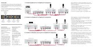

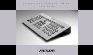

![The Sound of Minute Repeaters Bob Stuart - meridian-audio[.info]](https://img.yumpu.com/27188010/1/184x260/the-sound-of-minute-repeaters-bob-stuart-meridian-audioinfo.jpg?quality=85)