Understanding HDMI âEye Patternâ, âBERâ and âCliff ... - Audioquest
Understanding HDMI âEye Patternâ, âBERâ and âCliff ... - Audioquest
Understanding HDMI âEye Patternâ, âBERâ and âCliff ... - Audioquest

Create successful ePaper yourself
Turn your PDF publications into a flip-book with our unique Google optimized e-Paper software.
Submitted: August 28, 2007<br />
<strong>Underst<strong>and</strong>ing</strong> <strong>HDMI</strong> “Eye Pattern”,<br />
“BER” <strong>and</strong> “Cliff Effect”<br />
Xiaozheng Lu, Senior Vice President, Product Development, AudioQuest<br />
You probably have heard these terms. You are bound to hear them more <strong>and</strong> more<br />
in the near future. They are all related to the digital transmission performance <strong>and</strong><br />
test methods. Although digital is not new to home theater (digital audio connections<br />
have been around for a long time), <strong>HDMI</strong> is the first digital home theater technology<br />
which pushes the limit of high speed digital transmission, considerably raising the<br />
st<strong>and</strong>ard needed for stringent design <strong>and</strong> quality control monitoring.<br />
To better underst<strong>and</strong> digital transmission, let’s first take a look at analog video<br />
transmission.<br />
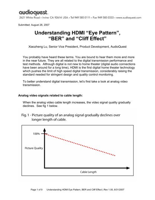
Analog video signals related to cable length:<br />
When the analog video cable length increases, the video signal quality gradually<br />
declines. See fig 1 below.<br />
Page 1 of 9 <strong>Underst<strong>and</strong>ing</strong> <strong>HDMI</strong> Eye Pattern, BER <strong>and</strong> Cliff Effect | Rev 1.00, 8/31/2007
The main types of analog video signal loss are:<br />
1) Amplitude loss: the result is a dimmer image.<br />
2) High frequency signal loss: the result is a softer image.<br />
3) Low frequency signal loss: the result is horizontal smearing on the image.<br />
There are marked differences in image quality between a good <strong>and</strong> bad cable. So<br />
it’s an easy up-sell to better cable products.<br />
No matter how bad the signal loss is, the display will still generally show a picture.<br />
Many viewers would not know how much image quality was lost without comparing<br />
pictures to a perfectly functioning display. In addition, there is no two-way<br />
communication between the source <strong>and</strong> display in an analog video based system.<br />
These are the two key reasons for the relatively low service call rate for analog video<br />
based systems.<br />
Digital video signals over long cables: the “Cliff Effect”<br />
Digital video signals behave quite differently from analog video. When the cable<br />
length increases, the image quality is perceived to be perfect by human eyes until a<br />
certain length. After that length, the image is either totally not viewable or disappears<br />
all together. The fig 2 below illustrates what it’s called “Cliff Effect”.<br />
Page 2 of 9 <strong>Underst<strong>and</strong>ing</strong> <strong>HDMI</strong> Eye Pattern, BER <strong>and</strong> Cliff Effect | Rev 1.00, 8/31/2007
Why should consumers pay for better cables if they are below the “Cliff Effect”?<br />
This is a hot topic among consumers <strong>and</strong> manufactures. One side insists that you<br />
do not need to pay more for higher performance cables, because as long as the<br />
signal has not exceed the cliff, even cheap <strong>HDMI</strong> cables will provide a quality image.<br />
The other side argues that there are always differences between higher <strong>and</strong> lower<br />
quality products <strong>and</strong> this is a difference worth paying for.<br />
Let’s use an analogy to further elaborate this point: schools usually use 60 out of<br />
100 points as the pass/fail threshold for students. Student A gets 95 points. Student<br />
B gets 65 points on their final exam. They both “pass” this final test. However, is<br />
their performance the same? Which one would you hire to work for you? The<br />
answer is quite obvious.<br />
Similarly, good <strong>and</strong> bad <strong>HDMI</strong> cables pass the test right up to the point where they<br />
fall off the “cliff”. But there are indeed differences between the two beyond the<br />
capability of the human eye to detect.<br />
Seeing is deceiving<br />
Even when the cable length is within the “cliff” <strong>and</strong> human eyes are unable to detect<br />
any defect of image, there are data errors already occurring in transmission. See fig<br />
3.<br />
Why wouldn’t we see these defects when we are near or on the cliff”? The answer<br />
is the built-in error correction technology used in digital transmission. The display<br />
Page 3 of 9 <strong>Underst<strong>and</strong>ing</strong> <strong>HDMI</strong> Eye Pattern, BER <strong>and</strong> Cliff Effect | Rev 1.00, 8/31/2007
can tolerate a certain amount of error bits per second; the picture would still be<br />
perfect as long as the error rate is below that threshold. Once the error rate exceeds<br />
the capability of the display, signal recovery may fail altogether.<br />
<strong>HDMI</strong> cables are not created equal. But if we can’t see the difference on the display,<br />
how would we know that there are meaningful differences? There are two industry<br />
st<strong>and</strong>ard tests for <strong>HDMI</strong> cable: the BER test <strong>and</strong> the “Eye Pattern” test.<br />
BER test:<br />
BER st<strong>and</strong>s for Bit Error Rate. In a BER test, the signal generator would output<br />
billions of data bits (per the <strong>HDMI</strong> st<strong>and</strong>ard) send them to the cable (or the input of<br />
other devices) <strong>and</strong> receive them from the other end of the cable (or the output of<br />
other devices). Then, a comparison is made bit by bit with the sent data. The BER<br />
display then shows the results as the total numbers of error bits in a given period of<br />
time (usually less than a second).<br />
The BER test accurately shows the real number of bad data bits a display could<br />
receive under a given condition. The higher the number, the worse the signal. The<br />
BER test is the most accurate real world test for <strong>HDMI</strong> cable performance <strong>and</strong><br />
quality control.<br />
Page 4 of 9 <strong>Underst<strong>and</strong>ing</strong> <strong>HDMI</strong> Eye Pattern, BER <strong>and</strong> Cliff Effect | Rev 1.00, 8/31/2007
Eye pattern test:<br />
“Eye pattern” is what the digital signal looks like on an oscilloscope. The traces of<br />
many 1s <strong>and</strong> 0s overlap together on the oscilloscope to form a pattern that<br />
resembles an eye shape. See Fig 5.<br />
The Eye pattern test shows many aspects of the digital signal, more specifically the<br />
following two:<br />
1) Signal amplitude: the height of the “eye” represents the signal amplitude. It must<br />
not fall into or become smaller than the marked diamond shaped area in the<br />
middle. Otherwise the signal will be too small for the display to recover. The<br />
“eye” will appear to be closed in the vertical direction<br />
2) Timing jitter: the rising <strong>and</strong> falling edges of digital bits do not always arrive at the<br />
precise time they should. This is called “timing jitter”. On an oscilloscope, it<br />
appears that the eye gets fuzzy in the horizontal direction as a result of some bits<br />
shifting left, some shifting right <strong>and</strong> overlapping together. The internal width of<br />
the eye can’t fall into or become narrower than the marked diamond area in the<br />
middle; otherwise the display won’t recover the data.<br />
In short, if the “eye” collapses in either horizontal or vertical direction, the signal is<br />
lost.<br />
BER vs. eye pattern test<br />
Both tests are essential in the <strong>HDMI</strong> industry. They are similar in that they both<br />
show elements of digital signal integrity. Fig 6 <strong>and</strong> 7 show these two different tests<br />
revealing the same cliff effects.<br />
Page 5 of 9 <strong>Underst<strong>and</strong>ing</strong> <strong>HDMI</strong> Eye Pattern, BER <strong>and</strong> Cliff Effect | Rev 1.00, 8/31/2007
However the two tests are different in some ways:<br />
The BER test shows the scale (how many) of data errors, but does not tell the cause<br />
of the problem. The equipment costs tens of thous<strong>and</strong>s of dollars. The test time is<br />
about a second for all 4 TMDS pairs <strong>and</strong> all other lines within an <strong>HDMI</strong> cable. These<br />
Page 6 of 9 <strong>Underst<strong>and</strong>ing</strong> <strong>HDMI</strong> Eye Pattern, BER <strong>and</strong> Cliff Effect | Rev 1.00, 8/31/2007
make the BER test the best for QC (quality control) <strong>and</strong> real world field support<br />
applications.<br />
The eye pattern test on the other h<strong>and</strong> shows the cause (what went wrong) of the<br />
problem, but not the scale (how many) of the data errors. This equipment costs<br />
hundreds of thous<strong>and</strong>s of dollars. This test takes about 15 to 20 minutes because<br />
the technician needs to test one pair at a time, <strong>and</strong> needs to analyze the pattern<br />
subjectively one by one. This makes the eye pattern test the best for engineering<br />
design <strong>and</strong> fault analysis.<br />
AudioQuest proudly utilizes both types of test gear <strong>and</strong> use them extensively<br />
throughout the design <strong>and</strong> 100% QC process to ensure the highest quality for<br />
each cable.<br />
Page 7 of 9 <strong>Underst<strong>and</strong>ing</strong> <strong>HDMI</strong> Eye Pattern, BER <strong>and</strong> Cliff Effect | Rev 1.00, 8/31/2007
<strong>HDMI</strong> cable length vs. max data rate<br />
In the analog world, we use b<strong>and</strong>width to describe the amount of information of the<br />
signal. The higher the picture resolution, the higher the signal b<strong>and</strong>width.<br />
In the digital world, we use data rate to describe the amount of data bits per second<br />
of the signal. The higher the picture resolution, the higher the refresh rate. The<br />
deeper the color, the higher the data rate. 720p <strong>and</strong> 1080i have about the same<br />
data rate of 2 Gbps (regular 24 bit encoding). 1080p has about twice the data rate at<br />
4 Gbps (regular 24 bit encoding). 48-bit deep color has about twice the data rate of<br />
the 24 bit encoding, or about 8 Gbps for 1080p deep color.<br />
The higher the data rate, the shorter the maximum length for a given <strong>HDMI</strong> cable<br />
design. See the chart below:<br />
Cable Length 2 m (6') 4.5 m (15') 9 m (30') 12 m (39') 15 m (49') 20 m (65') 40 m (130')<br />
Max data rate 25 Gbps 18 Gbps 9 Gbps 7 Gbps 5 Gbps 4 Gbps 2 Gbps<br />
Equiverlent Future Future 1080p 48bit 1080p 36bit 1080p 24bit 720p/1080i<br />
HDTV format<br />
Higher data rate signals post a bigger challenge to the long cables.<br />
Future proof your system<br />
Taking a look at the cable length <strong>and</strong> data rate from the cliff effect chart, it is clear<br />
that the higher the data rate, the closer the cliff.<br />
Page 8 of 9 <strong>Underst<strong>and</strong>ing</strong> <strong>HDMI</strong> Eye Pattern, BER <strong>and</strong> Cliff Effect | Rev 1.00, 8/31/2007
In other words, we can expect the cliff to “move in” with the advance of technology<br />
that enables higher data rate over time.<br />
From the discussion above, we see that there are absolute differences among<br />
cables. The worse the cable, the closer the cliff.<br />
A low quality cable that may work fine for the 1080i signal you are using today may<br />
not work for the 1080p signal you may use tomorrow. A good quality <strong>HDMI</strong> cable<br />
does not cost much more than a mediocre one, especially compared to the cost of<br />
the HDTV in your system.<br />
Summary<br />
In this article, we have discussed the cliff effect. Even in a given system<br />
combination where no picture defects are visible, there are plenty of data errors<br />
occurring. This is where the difference between a good <strong>and</strong> a bad cable becomes<br />
important. The tests to reveal the data error are the BER <strong>and</strong> Eye pattern testes.<br />
We have also found that the higher the data rate, the closer the cliff. Likewise, the<br />
worse the cable, the closer the cliff.<br />
Technology is constantly moving forward. We are offered higher <strong>and</strong> higher data<br />
rates for improved performance in our home entertainment systems. The use of high<br />
quality <strong>HDMI</strong> cable is a reliable <strong>and</strong> cost effective way to future proof your system.<br />
Should you have any questions or comments, please do not hesitate to contact your<br />
local AudioQuest RSM or call our technical support team here in Irvine at 800-747-<br />
2770.<br />
Please visit www.audioquest.com for more information.<br />
Page 9 of 9 <strong>Underst<strong>and</strong>ing</strong> <strong>HDMI</strong> Eye Pattern, BER <strong>and</strong> Cliff Effect | Rev 1.00, 8/31/2007