Applications Guide Tracer Graphical Programming - Trane
Applications Guide Tracer Graphical Programming - Trane Applications Guide Tracer Graphical Programming - Trane
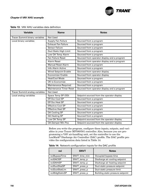
® Chapter 6 VAV AHU example Table 13: VAV AHU variables data definition Variable Name Notes Tracer Summit binary variables Not Used Local binary variables Supply Fan Failure Sourced from a program Exhaust Fan Failure Sourced from a program Sensor Failure Sourced from a program Duct Static High Limit Sourced from a program Low OA Temp Alarm Sourced from a program Fan Failure Reset Sourced from operator display and a program Alarm Reset Sourced from operator display and a program Manual Reset Alarm Sourced from a program Info Alarm Active Sourced from a program Wired Setpoint Enable Sourced from operator display Economizer Enable Sourced from operator display Heat/Cool Mode Sourced from a program OK to Economize Sourced from a program Maintenance Required Sourced from a program Maintenance Timer Reset Sourced from operator display and a program Tracer Summit analog variables Not Used Local analog variables Space Temp SP (OD) Setpoint sourced from the operator display Eff Occ Cool SP Sourced from a program Eff Occ Heat SP Sourced from a program Effective Cool SP Sourced from a program Effective Heat SP Sourced from a program DA Cooling SP Sourced from a program DA Heating SP Sourced from a program Low OA Temp SP Setpoint sourced from the operator display OA Damper Min Pos Setpoint sourced from the operator display Before you write the program, configure these inputs, outputs, and variables in your Tracer MP580/581 controller. Also, because you are programming a VAV air-handling unit, set the controller to use the LonMark ® Discharge Air Controller (DAC) profile. The DAC profile provides the configuration data listed in Table 14. Table 14: Network configuration inputs for the DAC profile nci SNVT Notes nciBypassTime SNVT_time_min Occupied bypass time nciDACISP SNVT_temp_p Discharge air cooling setpoint nciDAHtSP SNVT_temp_p Discharge air heating setpoint nciDuctStatSP SNVT_press_p Duct static pressure setpoint nciDuctStatLim SNVT_press_p Duct static pressure limit nciBldgStaticSP SNVT_press_p Building static pressure setpoint 110 CNT-APG001-EN
® Reviewing the sequence of operation Table 14: Network configuration inputs for the DAC profile (continued) nci SNVT Notes nciMALowLimitSP SNVT_temp_p Mixed air low limit setpoint nciOATSP SNVT_temp_p Outdoor air temperature (economizer changeover) setpoint nciSetpoints SNVT_temp_setpt Provides default unoccupied, occupied, and occupied standby cooling and heating setpoints Then make sure that the TGP editor is open and ready to go. CNT-APG001-EN 111
- Page 84 and 85: ® Chapter 4 Cooling tower with two
- Page 86 and 87: ® Chapter 4 Cooling tower with two
- Page 88 and 89: ® Chapter 4 Cooling tower with two
- Page 90 and 91: ® Chapter 4 Cooling tower with two
- Page 92 and 93: ® Chapter 4 Cooling tower with two
- Page 94 and 95: ® Chapter 4 Cooling tower with two
- Page 96 and 97: ® Chapter 4 Cooling tower with two
- Page 98 and 99: ® Chapter 4 Cooling tower with two
- Page 100 and 101: ® Chapter 4 Cooling tower with two
- Page 102 and 103: ® Chapter 4 Cooling tower with two
- Page 104 and 105: ® Chapter 5 Cooling tower with var
- Page 106 and 107: ® Chapter 5 Cooling tower with var
- Page 108 and 109: ® Chapter 5 Cooling tower with var
- Page 110 and 111: ® Chapter 5 Cooling tower with var
- Page 112 and 113: ® Chapter 5 Cooling tower with var
- Page 114 and 115: ® Chapter 5 Cooling tower with var
- Page 116 and 117: ® Chapter 5 Cooling tower with var
- Page 118 and 119: ® Chapter 5 Cooling tower with var
- Page 120 and 121: ® Chapter 5 Cooling tower with var
- Page 122 and 123: ® Chapter 5 Cooling tower with var
- Page 124 and 125: ® Chapter 5 Cooling tower with var
- Page 126 and 127: ® Chapter 5 Cooling tower with var
- Page 128 and 129: ® Chapter 5 Cooling tower with var
- Page 130 and 131: ® Chapter 6 VAV AHU example Review
- Page 132 and 133: ® Chapter 6 VAV AHU example contro
- Page 136 and 137: ® Chapter 6 VAV AHU example Figure
- Page 138 and 139: ® Chapter 6 VAV AHU example Figure
- Page 140 and 141: ® Chapter 6 VAV AHU example Figure
- Page 142 and 143: ® Chapter 6 VAV AHU example Figure
- Page 144 and 145: ® Chapter 6 VAV AHU example Figure
- Page 146 and 147: ® Chapter 6 VAV AHU example Figure
- Page 148 and 149: ® Chapter 6 VAV AHU example Figure
- Page 150 and 151: ® Chapter 6 VAV AHU example Figure
- Page 152 and 153: ® Chapter 6 VAV AHU example Writin
- Page 154 and 155: ® Chapter 6 VAV AHU example Indica
- Page 156 and 157: ® Chapter 6 VAV AHU example Figure
- Page 158 and 159: ® Chapter 6 VAV AHU example Alarm
- Page 160 and 161: ® Chapter 6 VAV AHU example charge
- Page 162 and 163: ® Chapter 6 VAV AHU example In thi
- Page 164 and 165: ® Chapter 6 VAV AHU example Figure
- Page 166 and 167: ® Chapter 6 VAV AHU example Effect
- Page 168 and 169: ® Chapter 6 VAV AHU example Summar
- Page 170 and 171: ® Chapter 7 Constant-volume AHU ex
- Page 172 and 173: ® Chapter 7 Constant-volume AHU ex
- Page 174 and 175: ® Chapter 7 Constant-volume AHU ex
- Page 176 and 177: ® Chapter 7 Constant-volume AHU ex
- Page 178 and 179: ® Chapter 7 Constant-volume AHU ex
- Page 180 and 181: ® Chapter 7 Constant-volume AHU ex
- Page 182 and 183: ® Chapter 7 Constant-volume AHU ex
®<br />
Chapter 6 VAV AHU example<br />
Table 13: VAV AHU variables data definition<br />
Variable Name Notes<br />
<strong>Tracer</strong> Summit binary variables Not Used<br />
Local binary variables Supply Fan Failure Sourced from a program<br />
Exhaust Fan Failure Sourced from a program<br />
Sensor Failure<br />
Sourced from a program<br />
Duct Static High Limit Sourced from a program<br />
Low OA Temp Alarm Sourced from a program<br />
Fan Failure Reset<br />
Sourced from operator display and a program<br />
Alarm Reset<br />
Sourced from operator display and a program<br />
Manual Reset Alarm Sourced from a program<br />
Info Alarm Active<br />
Sourced from a program<br />
Wired Setpoint Enable Sourced from operator display<br />
Economizer Enable Sourced from operator display<br />
Heat/Cool Mode<br />
Sourced from a program<br />
OK to Economize<br />
Sourced from a program<br />
Maintenance Required Sourced from a program<br />
Maintenance Timer Reset Sourced from operator display and a program<br />
<strong>Tracer</strong> Summit analog variables Not Used<br />
Local analog variables Space Temp SP (OD) Setpoint sourced from the operator display<br />
Eff Occ Cool SP<br />
Sourced from a program<br />
Eff Occ Heat SP<br />
Sourced from a program<br />
Effective Cool SP<br />
Sourced from a program<br />
Effective Heat SP<br />
Sourced from a program<br />
DA Cooling SP<br />
Sourced from a program<br />
DA Heating SP<br />
Sourced from a program<br />
Low OA Temp SP<br />
Setpoint sourced from the operator display<br />
OA Damper Min Pos Setpoint sourced from the operator display<br />
Before you write the program, configure these inputs, outputs, and variables<br />
in your <strong>Tracer</strong> MP580/581 controller. Also, because you are programming<br />
a VAV air-handling unit, set the controller to use the<br />
LonMark ® Discharge Air Controller (DAC) profile. The DAC profile provides<br />
the configuration data listed in Table 14.<br />
Table 14: Network configuration inputs for the DAC profile<br />
nci SNVT Notes<br />
nciBypassTime SNVT_time_min Occupied bypass time<br />
nciDACISP SNVT_temp_p Discharge air cooling setpoint<br />
nciDAHtSP SNVT_temp_p Discharge air heating setpoint<br />
nciDuctStatSP SNVT_press_p Duct static pressure setpoint<br />
nciDuctStatLim SNVT_press_p Duct static pressure limit<br />
nciBldgStaticSP SNVT_press_p Building static pressure setpoint<br />
110 CNT-APG001-EN


