

Applications Guide Tracer Graphical Programming - Trane
Applications Guide Tracer Graphical Programming - Trane
Applications Guide Tracer Graphical Programming - Trane

Create successful ePaper yourself
Turn your PDF publications into a flip-book with our unique Google optimized e-Paper software.
<strong>Applications</strong> <strong>Guide</strong><br />
<strong>Tracer</strong> <strong>Graphical</strong><br />
<strong>Programming</strong><br />
CNT-APG001-EN
®<br />
<strong>Applications</strong> <strong>Guide</strong><br />
<strong>Tracer</strong> <strong>Graphical</strong><br />
<strong>Programming</strong><br />
CNT-APG001-EN<br />
February 2002
CNT-APG001-EN<br />
®
®<br />
<strong>Tracer</strong> <strong>Graphical</strong> <strong>Programming</strong><br />
This guide and the information in it are the property of American Standard Inc. and may not be used or reproduced in whole or in part,<br />
without the written permission of American Standard Inc. <strong>Trane</strong> has a policy of continuous product and product data improvement and<br />
reserves the right to change design and specification without notice.<br />
Although <strong>Trane</strong> has tested the described software in this guide, no guarantee is offered that the software is error free.<br />
<strong>Trane</strong> reserves the right to revise this publication at any time and to make changes to its content without obligation to notify any personofsuchrevisionorchange.<br />
<strong>Trane</strong> may have patents or patent applications covering items in this publication. By providing this document, <strong>Trane</strong> does not imply<br />
giving license to these patents.<br />
®<br />
The following are trademarks or registered trademarks of <strong>Trane</strong>: Climate Changer, Rover, <strong>Tracer</strong>, <strong>Tracer</strong> Summit, and<br />
T-Series.<br />
®<br />
The following are trademarks or registered trademarks of their respective companies or organizations: LonTalk and LonMark<br />
from Echelon Corporation and Windows from Microsoft Corporation.<br />
Printed in the U.S.A.<br />
© 2002 American Standard Inc.<br />
CNT-APG001-EN
®<br />
Special notifications and formats<br />
The following notifications and formats may appear at appropriate locations throughout this manual. Read<br />
warnings and cautions carefully.<br />
!WARNING<br />
Indicates a potentially hazardous situation, which, if not avoided, could result in death or serious injury.<br />
!CAUTION<br />
Indicates a potentially hazardous situation, which, if not avoided, may result in minor or moderate injury.<br />
It may also be used to alert against unsafe practices.<br />
CAUTION<br />
Indicates a situation that may result in equipment or property-damage-only accidents.<br />
IMPORTANT<br />
Alerts installer, servicer, or operator to potential actions that could cause the product or system to<br />
operate improperly but will not likely result in potential for damage.<br />
Note:<br />
A note may be used to make the reader aware of useful information, to clarify a point, or to describe<br />
options or alternatives.<br />
◆<br />
This symbol precedes a procedure that consists of only a single step.<br />
➤ Explanatory information<br />
Text in this format provides explanations that you can read for further information on a particular subject<br />
or concept. The information is not necessary to complete the task.<br />
CNT-APG001-EN
®<br />
Contents<br />
Chapter 1 Using the <strong>Tracer</strong> <strong>Graphical</strong> <strong>Programming</strong> editor. . 1<br />
About this book. . . . . . . . . . . . .................................. 1<br />
Roverservicetooloverview.................................... 2<br />
About the <strong>Tracer</strong> MP580/581 controller . . . . . ..................... 2<br />
OpeningtheTGPeditor....................................... 2<br />
TGPeditor.................................................. 4<br />
Designspace............................................. 4<br />
Outputdisplay ........................................... 4<br />
Blocks .................................................. 5<br />
Menubar................................................ 5<br />
Toolbars................................................. 6<br />
Standardtoolbar...................................... 6<br />
Alignmenttoolbar..................................... 6<br />
Blocktoolbars......................................... 7<br />
Programtoolbar....................................... 8<br />
Showingorhidingtoolbars ............................. 8<br />
Shortcutmenus .......................................... 9<br />
Keyboardshortcuts ....................................... 9<br />
UsingonlineHelp........................................ 10<br />
Chapter2 Writingtheexhaustfanprogram............. 11<br />
Whatyouwilllearn...........................................11<br />
Skills . ..................................................11<br />
Conceptsanddefinitions...................................11<br />
Blocks ................................................. 12<br />
Reviewingthesequenceofoperation........................... 12<br />
Openinganewprogram ..................................... 15<br />
Editingprogramproperties................................... 15<br />
Addingablock ............................................. 17<br />
Editingblockproperties...................................... 18<br />
UsingaConstantblock....................................... 19<br />
Addingacomment.......................................... 21<br />
CNT-APG001-EN<br />
v
®<br />
Contents<br />
Arrangingblocks............................................21<br />
Selectingandmovingblocks...............................21<br />
Aligningblocks..........................................22<br />
AddingaCompareblock .....................................22<br />
AddinganOutputblock ......................................23<br />
Connecting blocks using wired connections. . . . . . . ...............24<br />
Savingaprogram...........................................25<br />
Compiling a program . . . . . . . . . . . . ............................26<br />
Closingaprogram...........................................27<br />
Summaryquestions.........................................27<br />
Chapter3 Modifyingtheexhaustfanprogram .......... 29<br />
Whatyouwilllearn..........................................29<br />
Skills. . . . . . . ............................................29<br />
Conceptsanddefinitions..................................29<br />
Blocks..................................................29<br />
Openinganexistingprogram .................................30<br />
Reviewingthesequenceofoperation...........................30<br />
Deletingablock.............................................31<br />
Addingadeadband..........................................32<br />
Greaterthan(assumecooling) .............................32<br />
Lessthan(assumeheating)................................32<br />
Centered(assumecooling) ................................33<br />
Addingavariable........................................34<br />
UsingaConstantblockforadeadbandvalue.................36<br />
Connecting blocks to a Deadband block . . . . . . . ...............36<br />
Addingalarmindication......................................36<br />
Addinganalarmvariable..................................36<br />
Implementingatestforsensorfailure.......................37<br />
UsingaSwitchblock.........................................38<br />
AddingaSwitchblock ....................................38<br />
Connecting the Switch block . . . ............................39<br />
CompletingtheSwitchblockconnections....................40<br />
SimplifyingtheprogramwithanOrblock.......................41<br />
Printingaprogram ..........................................42<br />
Downloadingaprogram......................................43<br />
Debugging a program. . . . . . . . . . . . ............................43<br />
Uploadingaprogram........................................44<br />
Summaryquestions.........................................45<br />
vi<br />
CNT-APG001-EN
®<br />
Contents<br />
Chapter 4 Cooling tower with two-speed fan example . . . . 47<br />
Whatyouwilllearn.......................................... 47<br />
Skills . ................................................. 47<br />
Conceptsanddefinitions.................................. 47<br />
Blocks ................................................. 47<br />
Reviewingthesequenceofoperation........................... 48<br />
Condenser water pump . . ................................. 48<br />
Coolingtowerfan........................................ 48<br />
Sumpheater............................................ 48<br />
Alarms................................................. 48<br />
Determiningaprogrammingapproach ......................... 52<br />
Settingtheprogramproperties................................ 52<br />
Writing the alarms module . . ................................. 53<br />
Adding the input blocks. . ................................. 54<br />
Addingtheoutputblock .................................. 55<br />
Monitoringthesumptemperature.......................... 55<br />
Comparing the sump temperature with the sump alarm setpoint<br />
andthefreezingpoint................................ 55<br />
Timingthesumptemperaturealarm..................... 56<br />
Controllingthesumptemperaturealarm................. 57<br />
Indicatinganalarmforanytemperaturesensorfailure......... 58<br />
Implementingthealarmresetfunction...................... 60<br />
AddingaLatchblocktocontrolthealarm................. 61<br />
Turningthealarmresetoffautomatically................. 63<br />
Addingpagestoyourprogram................................ 65<br />
Writing the sump heater module . . . . . . . . . . .................... 66<br />
Adding the input blocks. . ................................. 66<br />
Addingwirelessconnections........................... 66<br />
Adding the other input blocks . . . . . . .................... 68<br />
Addingtheoutputblock .................................. 69<br />
Controlling the sump heater under normal conditions . . ....... 69<br />
Comparing the outdoor air temperature with the freezing point. . 70<br />
Controllingthesumpheateronoroff....................... 70<br />
Writing the cooling tower fan module . . . . . . .................... 71<br />
Adding the input blocks. . ................................. 71<br />
Addingtheoutputblocks.................................. 72<br />
Startingthefanatlowspeed .............................. 72<br />
Transitioningthefantohighspeed ......................... 73<br />
Transitioning the fan based on supply temp. . . . . . . . ....... 73<br />
Transitioningthefanbasedontime ..................... 75<br />
Summaryquestions......................................... 78<br />
CNT-APG001-EN<br />
vii
®<br />
Contents<br />
Chapter 5 Cooling tower with variable-speed fan example 79<br />
Whatyouwilllearn..........................................79<br />
Skills. . . . . . . ............................................79<br />
Conceptsanddefinitions..................................79<br />
Blocks..................................................79<br />
Reviewingthesequenceofoperation...........................80<br />
Condenser water pump . . . . . . . ............................80<br />
Coolingtowerfan........................................80<br />
Sumpheater............................................80<br />
Alarms.................................................80<br />
Calculations.............................................80<br />
RefreshingtheTGPeditor ....................................84<br />
Determiningaprogrammingapproach..........................84<br />
Editingtheprogramproperties................................84<br />
Modifying the alarms module . . . . . ............................85<br />
Writing the calculations module . . . ............................86<br />
Calculating change in water temperature across the cooling tower .<br />
86<br />
Calculatingtheambientwet-bulbtemperature................87<br />
Calculatingtheapproachtemperature.......................87<br />
Writing the cooling tower fan module. . . . . . . . . . . . ...............88<br />
Startingandstoppingthefan ..............................88<br />
Imposinglimits..........................................89<br />
ImplementingPIDcontrol .................................91<br />
SettingupthePIDblockproperties.......................91<br />
IncorporatingthePIDblock.............................93<br />
Writing the condenser water pump module . . . . . . . ...............94<br />
Adding the input blocks . . . . . . . ............................95<br />
Addingtheoutputblocks..................................95<br />
Determiningwhentostartandstopthepump ................96<br />
AddingaFeedbackAlarmblock .........................96<br />
Checking conditions to start and stop the pump . . . . . . . . . . . . 98<br />
Summaryquestions........................................104<br />
Chapter 6 VAV AHU example . . ...................... 105<br />
Whatyouwilllearn.........................................105<br />
Skills. . . . . . . ...........................................105<br />
Conceptsanddefinitions.................................105<br />
Blocks.................................................105<br />
viii<br />
CNT-APG001-EN
®<br />
Contents<br />
Reviewingthesequenceofoperation.......................... 106<br />
Modesandsetpoints.................................... 106<br />
Occupiedmode..................................... 106<br />
Unoccupiedmode................................... 106<br />
Spacesetpoints..................................... 106<br />
Dischargeairsetpoints............................... 107<br />
Heat/Coolarbitration................................. 107<br />
Control................................................ 107<br />
Supply fan . . . . . . . . . ................................ 107<br />
Outdoor air damper. . ................................ 107<br />
Exhaustfan......................................... 108<br />
Coolingvalve....................................... 108<br />
Heatingvalve....................................... 108<br />
Alarms ............................................ 108<br />
Determiningaprogrammingapproach .........................113<br />
Writingthefancontrolprogram...............................114<br />
Controlling the supply fan. ................................114<br />
Controllingtheductstaticpressure.........................116<br />
Controllingtheexhaustfan................................117<br />
Writingthedischargeaircontrolprogram.......................119<br />
Controlling the mixed air and outdoor air damper . . . . . . ...... 120<br />
Determining whether to economize. . ................... 121<br />
Determining the outdoor air damper position . . . . . . ...... 122<br />
Controllingthecoolingvalve ............................. 123<br />
Controllingtheheatingvalve............................. 124<br />
Writingthealarmsprogram ................................. 128<br />
Indicatingmanualresetalarms............................ 130<br />
Indicatingauto-resetalarms.............................. 131<br />
Controllingalarmindicationandreset...................... 131<br />
Writingthemodeandsetpointsprogram ...................... 134<br />
Calculatingtheeffectivespacesetpoints.................... 135<br />
Calculatingtheoffsetvalues........................... 136<br />
Calculating the effective cooling and heating setpoints. . . . . 137<br />
Effectivesetpointcalculationexamples ................. 138<br />
Validatingthedischargeairsetpoints ...................... 140<br />
Determiningtheheat/coolmode .......................... 141<br />
Viewingprogramstatus..................................... 143<br />
Summaryquestions........................................ 144<br />
CNT-APG001-EN<br />
ix
®<br />
Contents<br />
Chapter7 Constant-volumeAHUexample............. 145<br />
Whatyouwilllearn.........................................145<br />
Skills. . . . . . . ...........................................145<br />
Conceptsanddefinitions.................................145<br />
Block..................................................145<br />
Reviewingthesequenceofoperation..........................146<br />
Modesandsetpoints ....................................146<br />
Occupied mode (including occupied bypass) . . . . . . . . . . . . . 146<br />
Occupied standby mode . . . ...........................146<br />
Unoccupied mode (including night heat/cool). . . . . . . . . . . . . 147<br />
Spacesetpoints .....................................147<br />
Dischargeairsetpoints ...............................147<br />
Heat/Coolarbitration.................................147<br />
Control................................................148<br />
Supply fan. . . . . . . . . . . . . . . ...........................148<br />
Outdoor air damper . . . . . . . ...........................148<br />
Exhaustfan.........................................148<br />
Coolingvalve .......................................148<br />
Heatingvalve .......................................149<br />
Humidification ......................................149<br />
Dehumidification ....................................149<br />
Alarms.............................................149<br />
Determiningaprogrammingapproach.........................154<br />
Writingthefancontrolprogram ..............................155<br />
Controlling the supply fan . . . . . ...........................155<br />
Controllingtheexhaustfan...............................156<br />
Writingthemixedaircontrolprogram.........................158<br />
Writingthedischargeaircontrolprogram......................164<br />
Calculatingthedischargeairsetpoint.......................165<br />
Implementing humidification and dehumidification . . . . . . . . . . . 166<br />
Controllingthecoolingvalve ..........................169<br />
Controllingtheheatingvalve ..........................171<br />
Controllingthehumidifier.............................172<br />
Writingthealarmsprogram..................................176<br />
Writingthemodeandsetpointsprogram.......................180<br />
Implementing effective space setpoint calculation . . . . . . . . . . . . 181<br />
Determiningtheheat/coolmode...........................183<br />
Addingnightheat/cool...................................184<br />
Summaryquestions........................................187<br />
x<br />
CNT-APG001-EN
®<br />
Contents<br />
Chapter 8<br />
Constant-volume AHU with warm-up, pre-cool,<br />
andcommunications.....................189<br />
Whatyouwilllearn......................................... 189<br />
Conceptsanddefinitions................................. 189<br />
Block ................................................. 189<br />
Reviewingthesequenceofoperation.......................... 190<br />
Modes,setpoints,andcommunications .................... 190<br />
Occupiedmode(includingoccupiedbypass)............. 190<br />
Occupied standby mode . . . . . . . . . . . ................... 190<br />
Unoccupiedmode(includingnightheat/cool)............ 191<br />
Warm-upandpre-coolmodes......................... 191<br />
Setpoints........................................... 191<br />
Heat/Coolarbitration................................. 192<br />
Communications.................................... 192<br />
Control................................................ 193<br />
Supply fan . . . . . . . . . ................................ 193<br />
Outdoor air damper. . ................................ 193<br />
Exhaustfan......................................... 193<br />
Coolingvalve....................................... 193<br />
Heatingvalve....................................... 194<br />
Humidification...................................... 194<br />
Dehumidification.................................... 194<br />
Alarms ............................................ 194<br />
Determiningaprogrammingapproach ........................ 199<br />
Writingthefancontrolprogram.............................. 200<br />
Writingthemixedaircontrolprogram......................... 200<br />
Writingthedischargeaircontrolprogram...................... 205<br />
Whethertohumidifyordehumidify........................ 205<br />
Controllingthecoolingvalve ............................. 206<br />
Controllingtheheatingvalve............................. 208<br />
Writingthealarmsprogram ................................. 212<br />
Writingthemodeandsetpointsprogram ...................... 213<br />
Modifyingtheeffectivesetpointcalculation................. 213<br />
Addingthepre-coolandwarm-updecisions................. 214<br />
Writingthecommunicationsprogram......................... 218<br />
Summaryquestions........................................ 225<br />
<strong>Programming</strong> best practices . . ..............227<br />
CNT-APG001-EN<br />
xi
®<br />
Contents<br />
Summary-question answers. ............... 235<br />
Chapter2,“Writingtheexhaustfanprogram” ..................235<br />
Chapter3,“Modifyingtheexhaustfanprogram”................235<br />
Chapter4,“Coolingtowerwithtwo-speedfanexample”..........236<br />
Chapter 5, “Cooling tower with variable-speed fan example” . . . . . . 236<br />
Chapter6,“VAVAHUexample” ..............................237<br />
Chapter 7, “Constant-volume AHU example” . . . . . . ..............241<br />
Chapter 8, “Constant-volume AHU with warm-up, pre-cool, and<br />
communications”.........................................243<br />
Index................................... 249<br />
xii<br />
CNT-APG001-EN
®<br />
Figures<br />
Chapter 1 Using the <strong>Tracer</strong> <strong>Graphical</strong> <strong>Programming</strong> editor. . 1<br />
Figure 1: Rover application window . . . . . . . . ..................... 3<br />
Figure 2: TGP editor running in Rover service tool . . . . . . . . . ........ 4<br />
Figure3:Blockstructure....................................... 5<br />
Figure4:TGPeditormenubar ................................. 6<br />
Figure5:Standardtoolbar..................................... 6<br />
Figure6:Alignmenttoolbar.................................... 6<br />
Figure7:Blocktoolbars....................................... 7<br />
Figure8:Programtoolbar ..................................... 8<br />
Figure9:Shortcutmenu....................................... 9<br />
Chapter2 Writingtheexhaustfanprogram............. 11<br />
Figure 10: Equipment room exhaust fan data .................... 12<br />
Figure 11: Equipment room exhaust fan wiring diagram . . . . ....... 14<br />
Figure12:ProgramPropertiesdialogbox ....................... 16<br />
Figure13:Input(Hardware)block.............................. 18<br />
Figure14:InputPropertiesdialogbox .......................... 18<br />
Figure 15: Equip Rm Space Temp input block .................... 19<br />
Figure16:Constantblockindesignspace....................... 20<br />
Figure17:ConstantPropertiesdialogbox....................... 20<br />
Figure18:Constantblocksetto85.0 ........................... 20<br />
Figure19:CommentaddedtodescribetheConstantblock......... 21<br />
Figure20:Blocksalignedleft.................................. 22<br />
Figure21:GreaterThanblockinprogram....................... 23<br />
Figure22:Output(Hardware)blockindesignspace............... 23<br />
Figure 23: Equip Rm Fan On/Off output block .................... 23<br />
Figure 24: Cursor in wire mode over a valid connection . . . . ....... 24<br />
Figure 25: Cursor in wire mode on an invalid connection . . . ....... 24<br />
Figure 26: Analog wired connection . . . . . . . . .................... 25<br />
Figure 27: Completed Equip Room Exhaust Fan program . . . ....... 25<br />
Figure28:Compilationresultsinoutputdisplay.................. 26<br />
CNT-APG001-EN<br />
xiii
®<br />
Figures<br />
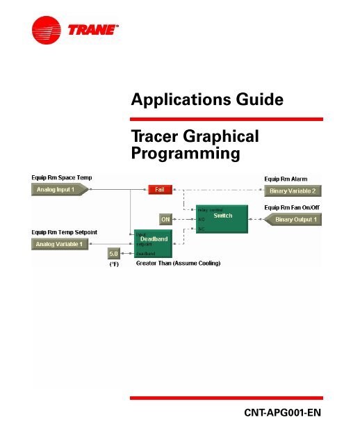
Chapter3 Modifyingtheexhaustfanprogram .......... 29<br />
Figure 29: Equipment room exhaust fan program . . ...............30<br />
Figure 30: Modified equipment room exhaust fan data . . . . . . . . . . . . 31<br />
Figure 31: Deadband function with greater than (assume cooling)<br />
relationship...............................................32<br />
Figure 32: Deadband function with less than (assume heating)<br />
relationship...............................................33<br />
Figure 33: Deadband function with centered (assume cooling)<br />
relationship...............................................33<br />
Figure34:ProgramwithDeadbandblock........................34<br />
Figure35:VariablePropertiesdialogbox........................35<br />
Figure 36: Equip Rm Temp Setpoint variable block . ...............35<br />
Figure37:Programwithdeadband.............................36<br />
Figure 38: Equip Rm Alarm binary variable in the design space . . . . . 37<br />
Figure39:ProgramwithFailblock..............................38<br />
Figure40:Programwithswitchblock...........................38<br />
Figure 41: Program with Switch block connected. . . ...............39<br />
Figure 42: Program compilation results in output display. . . . . . . . . . . 40<br />
Figure43:Programwitherrorindication ........................40<br />
Figure 44: Program with Switch block connected correctly. . . . . . . . . . 41<br />
Figure45:ProgramwithOrblock ..............................42<br />
Figure46:TGPprogramindebugrun...........................43<br />
Chapter 4 Cooling tower with two-speed fan example .... 47<br />
Figure 47: Cooling tower with two-speed fan drive data. . . . . . . . . . . . 49<br />
Figure 48: Cooling tower with two-speed fan drive wiring diagram . . 51<br />
Figure 49: Cooling tower with two-speed fan drive<br />
programproperties.........................................53<br />
Figure 50: Input blocks for the alarms module . . . . . ...............54<br />
Figure 51: Alarms module output . . ............................55<br />
Figure 52: Comparing the sump temperature to the alarm setpoint<br />
andthefreezingpoint ......................................56<br />
Figure53:Delayonstarttimingdiagram........................56<br />
Figure54:ImplementingtheDelayonStartblock.................57<br />
Figure55:Sumptemperaturealarmlogic .......................58<br />
Figure56:FailPropertiesdialogbox............................58<br />
Figure 57: Fail block added to test temperature sensors . . . . . . . . . . . . 59<br />
Figure 58: Test for temperature sensor failure complete . . . . . . . . . . . . 59<br />
Figure59:Latchblockintimedmode...........................60<br />
Figure60:Latchblockinmanualmode..........................60<br />
xiv<br />
CNT-APG001-EN
®<br />
Figures<br />
Figure 61: Latch block timing diagram, relationship<br />
betweentriggerandoutput ................................. 60<br />
Figure 62: Latch block timing diagram, relationship<br />
betweentrigger,cancel,andoutput........................... 61<br />
Figure63:LatchPropertiesdialogbox.......................... 62<br />
Figure64:Alarmresetimplemented ........................... 62<br />
Figure 65: Alarm reset module . . . . . . . . . . . . .................... 63<br />
Figure 66: Alarm reset module . . . . . . . . . . . . .................... 64<br />
Figure 67: Alarms module completed. . . . . . . .................... 65<br />
Figure 68: Creating Wireless connection block . . . . . . . . . . . . ....... 67<br />
Figure69:Wirelesswriteconnection........................... 67<br />
Figure 70: Using Wireless connection block. . .................... 68<br />
Figure71:Wirelessread...................................... 68<br />
Figure 72: Input blocks for sump heater module . . . . . . . . . . . ....... 69<br />
Figure 73: Output block for sump heater module . . . . . . . . . . ....... 69<br />
Figure 74: Deadband incorporated in sump heater module . . ....... 70<br />
Figure 75: Less Than or Equal comparison in sump heater module . . 70<br />
Figure76:Sumpheatermodulecompleted...................... 71<br />
Figure 77: Input blocks for the cooling tower fan module . . . ....... 72<br />
Figure78:Outputblocksforthecoolingtowerfanmodule......... 72<br />
Figure79:Startthefanatlowspeed ........................... 73<br />
Figure80:Deadbandsusedtocontrolfanspeed ................. 74<br />
Figure81:Addingthefanathighspeed......................... 75<br />
Figure 82: Cooling tower fan module complete. . . . . . . . . . . . ....... 76<br />
Figure 83: Completed cooling tower with two-speed fan program . . . 77<br />
Chapter 5 Cooling tower with variable-speed fan example. 79<br />
Figure84:Coolingtowerwithvariable-speedfandrivedata........ 81<br />
Figure 85: Cooling tower with variable-speed fan drive<br />
wiringdiagram............................................ 83<br />
Figure 86: Alarms module completed. . . . . . . .................... 85<br />
Figure87:Changeintemperaturecalculation.................... 86<br />
Figure88:Wet-bulbtemperaturecalculation..................... 87<br />
Figure 89: Calculations module complete . . . .................... 88<br />
Figure90:Previouscoolingtowerfanmodule ................... 89<br />
Figure91:Usingadeadbandtostartandstopthefan............. 89<br />
Figure 92: Checking a setpoint against limits<br />
usingtheMinandMaxblocks ............................... 90<br />
Figure 93: Checking a setpoint against limits using the Limit block. . . 90<br />
Figure94:PIDPropertiesdialogbox............................ 91<br />
Figure 95: Cooling tower fan module complete. . . . . . . . . . . . ....... 94<br />
CNT-APG001-EN<br />
xv
®<br />
Figures<br />
Figure 96: Input blocks for the condenser water pump module . . . . . . 95<br />
Figure 97: Output blocks for the condenser water pump module. . . . . 96<br />
Figure98:FeedbackAlarmPropertiesdialogbox .................97<br />
Figure99:FeedbackAlarmblock...............................98<br />
Figure100:Pumpstart/stopmodule............................99<br />
Figure 101: Adjusted pump start/stop module . . . . . ..............100<br />
Figure 102: Condenser water pump module completed . . . . . . . . . . . 101<br />
Figure 103: Complete cooling tower<br />
withvariable-speedfanprogram ............................ 101<br />
Chapter 6 VAV AHU example . . ...................... 105<br />
Figure104:VAVairhandler ..................................106<br />
Figure105:VAVAHUwiringdiagram.......................... 112<br />
Figure106:Fancontrolprogramproperties..................... 114<br />
Figure 107: Supply fan control . . . . . ........................... 116<br />
Figure108:Ductstaticpressurecontrol ........................ 116<br />
Figure 109: Supply fan PID properties . . . . . . . . . . . . .............. 117<br />
Figure110:Exhaustfancontrol ............................... 118<br />
Figure111:Completefancontrolprogram ...................... 118<br />
Figure 112: Discharge air control program properties . . . . . . . . . . . . . 120<br />
Figure113:Determiningwhethertoeconomize..................121<br />
Figure 114: Controlling outdoor air damper position ..............122<br />
Figure115:Operatethecoolingvalve?.........................123<br />
Figure 116: Controlling the cooling valve . . . . . . . . . ..............124<br />
Figure 117: Controlling the heating valve . . . . . . . . . ..............125<br />
Figure118:Completedischargeairprogram ....................126<br />
Figure119:Alarmsprogramproperties.........................129<br />
Figure120:Manualresetalarms..............................130<br />
Figure121:Auto-resetalarms ................................131<br />
Figure122:Alarmindicationandreset.........................132<br />
Figure123:Completedalarmsprogram........................133<br />
Figure124:Modeandsetpointsprogramproperties..............135<br />
Figure125:OffsetcalculationinTGP...........................137<br />
Figure126:EffectivesetpointcalculationinTGP.................140<br />
Figure127:Validatingdischargeairsetpoints ...................140<br />
Figure128:Heat/Coolmodedecision..........................141<br />
Figure 129: Completed modes and setpoints program . . . . . . . . . . . . 141<br />
Figure130:ProgramSummarydialogbox......................143<br />
xvi<br />
CNT-APG001-EN
®<br />
Figures<br />
Chapter7<br />
Constant-volumeAHUexample.............145<br />
Figure131:Constant-volumeairhandler....................... 146<br />
Figure132:Constant-volumeAHUwiringdiagram............... 153<br />
Figure133:Fancontrolprogramproperties..................... 155<br />
Figure 134: Supply fan control . . . . . . . . . . . . ................... 156<br />
Figure135:Exhaustfancontrol............................... 157<br />
Figure136:Completedfancontrolprogram .................... 157<br />
Figure137:Mixedaircontrolprogramproperties................ 159<br />
Figure 138: Determining whether to economize . . . . . . . . . . . ...... 160<br />
Figure 139: Night heat/cool incorporated<br />
intooutsideairdampercontrol ............................. 161<br />
Figure 140: Controlling the outdoor air damper position . . . . ...... 162<br />
Figure141:Completedmixedaircontrolprogram............... 163<br />
Figure142:Dischargeaircontrolprogramproperties............. 165<br />
Figure143:Dischargeairreset ............................... 166<br />
Figure144:DischargeairresetPIDproperties................... 166<br />
Figure145:Resetblocklinearequationplot..................... 168<br />
Figure146:Whethertohumidify/dehumidify ................... 169<br />
Figure147:Operatethecoolingvalve?......................... 170<br />
Figure148:Controllingthecoolingvalve....................... 171<br />
Figure149:Controllingtheheatingvalve....................... 172<br />
Figure150:Controllingthehumidifier......................... 173<br />
Figure151:Completeddischargeaircontrolprogram............ 173<br />
Figure152:Alarmsprogramproperties........................ 177<br />
Figure153:Manualresetalarms.............................. 177<br />
Figure154:Autoresetalarms................................ 178<br />
Figure155:Alarmindicationandreset......................... 178<br />
Figure156:Completedalarmsprogram........................ 179<br />
Figure157:Modeandsetpointsprogramproperties ............. 181<br />
Figure158:Offsetcalculation ................................ 182<br />
Figure 159: Space temperature setpoint source determination . . . . . 182<br />
Figure160:Effectivesetpointcalculation....................... 183<br />
Figure161:Heat/Coolmodedecision.......................... 183<br />
Figure162:Nightheat/cooldecision........................... 184<br />
Figure163:Completedmodesandsetpointsprogram............ 185<br />
CNT-APG001-EN<br />
xvii
®<br />
Figures<br />
Chapter 8<br />
Constant-volume AHU with warm-up, pre-cool,<br />
andcommunications..................... 189<br />
Figure164:Constant-volumeairhandler .......................190<br />
Figure 165: Modified constant-volume AHU wiring diagram . . . . . . . 198<br />
Figure 166: Economize decision with communicated values . . . . . . . 201<br />
Figure 167: Decision incorporating pre-cool and warm-up modes. . . 202<br />
Figure 168: Outdoor air damper control . . . . . . . . . . ..............203<br />
Figure169:Completedmixedaircontrolprogram ...............203<br />
Figure170:Dehumidifyorhumidify? ..........................205<br />
Figure 171: Modulate or open the cooling valve? . . ..............207<br />
Figure 172: Controlling the cooling valve . . . . . . . . . ..............208<br />
Figure 173: Controlling the heating valve . . . . . . . . . ..............209<br />
Figure 174: Completed discharge air control program. . . . . . . . . . . . . 210<br />
Figure 175: Space temperature setpoint source determination . . . . . 213<br />
Figure176:Pre-coolandwarm-updecisions ....................215<br />
Figure 177: Completed modes and setpoints program . . . . . . . . . . . . 215<br />
Figure178:Communicationsprogramproperties................219<br />
Figure179:Transmittingtemperatures.........................219<br />
Figure180:Transmittingtheeffectivesetpoint...................220<br />
Figure181:Transmittingeffectiveoccupancy....................220<br />
Figure182:IndicatingmodewithinnvoUnitStatus ...............222<br />
Figure183:Remainingunitstatusitems........................222<br />
Figure184:Completedcommunicationsprogram................223<br />
<strong>Programming</strong> best practices. ............... 227<br />
Figure185:Programproperties...............................228<br />
Figure186:Inputsontheleft,outputsontheright ...............229<br />
Figure 187: Checking the space temperature input for failure. . . . . . . 230<br />
Figure 188: Using wireless connections . . . . . . . . . . ..............231<br />
Summary-question answers. ............... 235<br />
Figure 189: Equip Room Exhaust Fan program with a modification . 236<br />
Figure190:FeedbackAlarmblocksubstitution...................236<br />
Figure 191: Automatically resetting the alarm reset<br />
without a Switch block . . . . . . . . . . ...........................237<br />
Figure 192: Using outdoor air enthalpy. . . . . . . . . . . ..............238<br />
Figure193:FanMaintenancecalculationsetup..................238<br />
Figure194:Maintenancetimerindicationandreset ..............239<br />
Figure195:Addingasetpointsourceoption ....................239<br />
Figure196:Effectivesetpointcalculation.......................240<br />
Figure197:Scheduleapplicationoccupancyinputs...............241<br />
xviii<br />
CNT-APG001-EN
®<br />
Figures<br />
Figure 198: Checking a network variable input for valid data . ...... 242<br />
Figure199:AddingnviEmergOverride......................... 244<br />
Figure200:Valveoverrideinterpretation....................... 245<br />
Figure201:Coolingvalveoverride............................ 246<br />
Figure202:Heatingvalvecontrolwithoverride ................. 246<br />
Figure203:Modifiedmanualresetalarmlogic.................. 247<br />
Index...................................249<br />
CNT-APG001-EN<br />
xix
®<br />
Figures<br />
xx<br />
CNT-APG001-EN
®<br />
Tables<br />
Chapter 1 Using the <strong>Tracer</strong> <strong>Graphical</strong> <strong>Programming</strong> editor. . 1<br />
Table1:Keyboardshortcuts.................................... 9<br />
Chapter2 Writingtheexhaustfanprogram............. 11<br />
Table2:Equipmentroomexhaustfandatadefinition.............. 13<br />
Chapter3<br />
Modifyingtheexhaustfanprogram...........29<br />
Table 3: Modified equipment room exhaust fan data definition. . . . . . 31<br />
Table 4: Variable block read or write rules for each control source . . . 34<br />
Chapter 4 Cooling tower with two-speed fan example . . . . 47<br />
Table 5: Cooling tower with two-speed fan drive data definition. . . . . 49<br />
Table6:Alarmresetmodulestatetable......................... 64<br />
Chapter 5 Cooling tower with variable-speed fan example. 79<br />
Table 7: Cooling tower with variable-speed fan drive data definition . 81<br />
Table8:Feedbackalarmrelationships .......................... 97<br />
Table9:Pumpstart/stopmodulestatetable ..................... 99<br />
Table 10: Pump start/stop module with successful start . . . . . ...... 100<br />
Table 11: Pump start/stop module with failure to confirm flow . . . . . 100<br />
Chapter 6 VAV AHU example ........................ 105<br />
Table 12: VAV AHU inputs and outputs data definition . . . . . . ...... 109<br />
Table13:VAVAHUvariablesdatadefinition.....................110<br />
Table14:NetworkconfigurationinputsfortheDACprofile.........110<br />
Table15:Controlfunctionswithineachprogram .................113<br />
Table16:Defaultandadjustablesetpointvalues................. 138<br />
Table17:Effectivesetpointvalues ............................ 139<br />
CNT-APG001-EN<br />
xxi
®<br />
Tables<br />
Chapter7 Constant-volumeAHUexample............. 145<br />
Table 18: Constant-volume AHU inputs and outputs data definition . 150<br />
Table 19: Constant-volume AHU variables data definition . . . . . . . . . 151<br />
Table 20: Network configuration inputs for the SCC profile . . . . . . . . 152<br />
Table 21: Network variable inputs . . ...........................152<br />
Table22:Controlfunctionswithineachprogram.................154<br />
Chapter 8<br />
Constant-volume AHU with warm-up, pre-cool,<br />
andcommunications..................... 189<br />
Table 23: Modified constant-volume AHU inputs and outputs<br />
datadefinition............................................195<br />
Table 24: Modified constant-volume AHU variables data definition. . 195<br />
Table 25: Network configuration inputs for the SCC profile . . . . . . . . 197<br />
Table 26: Network variable inputs for the SCC profile . . . . . . . . . . . . . 197<br />
Table 27: Network variable outputs for the SCC profile . . . . . . . . . . . . 197<br />
Table28:Controlfunctionswithineachprogram.................199<br />
Table29:SNVT_hvac_statusstructurecontents..................220<br />
Table30:SNVT_hvac_mode(hvac_t)enumerations ..............221<br />
Table 31: Enumerations revealed by the De-Enumerator block. . . . . . 221<br />
<strong>Programming</strong> best practices. ............... 227<br />
Table 32: Grouping programming tasks into programs. . . . . . . . . . . . 232<br />
Summary-question answers. ............... 235<br />
Table 33: Network variable input (nvi) and<br />
network configuration input (nci) invalid values . . ..............242<br />
Table34:SNVT_hvac_emerg(emerg_t)enumerations ............243<br />
Table35:SNVT_hvac_overridstructurecontents.................244<br />
Table 36: SNVT_hvac_overrid (hvac_overrid_t) enumerations . . . . . . 245<br />
Index................................... 249<br />
xxii<br />
CNT-APG001-EN
®<br />
Chapter 1<br />
Using the <strong>Tracer</strong> <strong>Graphical</strong><br />
<strong>Programming</strong> editor<br />
Use the <strong>Tracer</strong> <strong>Graphical</strong> <strong>Programming</strong> (TGP) editor to create custom<br />
programs for the <strong>Tracer</strong> MP580/581 programmable controller.<br />
About this book<br />
This book is a tutorial with instructions and examples you can use to<br />
learn to write programs in the TGP editor. To get the most from this book,<br />
have a <strong>Tracer</strong> MP580/581 powered up and ready to be programmed. As<br />
you read through the chapters, follow the instructions. At the end of each<br />
chapter, you will have a configured and programmed <strong>Tracer</strong> MP580/581<br />
controller for that chapter.<br />
For each chapter, complete the following steps:<br />
1. Read and analyze the sequence of operation.<br />
2. Configure the inputs, outputs, and variables in the <strong>Tracer</strong> MP580/581<br />
plug-in using the Rover service tool.<br />
3. Follow the instructions and build the programs as you go through the<br />
tutorial.<br />
4. Compile and download the programs to your controller.<br />
5. Review the programs and answer the summary questions at the end<br />
of each chapter.<br />
Note:<br />
Many of the chapters in this book build on previous chapters, so<br />
be sure to complete the chapters in the order presented.<br />
➤ Explanatory information<br />
Text in this format provides explanations that you can read for further<br />
information on a particular subject or concept. The information is<br />
not necessary to complete the task.<br />
CNT-APG001-EN 1
®<br />
Chapter 1 Using the <strong>Tracer</strong> <strong>Graphical</strong> <strong>Programming</strong> editor<br />
Rover service tool overview<br />
The Rover service tool is the setup and configuration tool for the <strong>Tracer</strong><br />
MP580/581. It is analogous to PCM Edit for the PCM and UPCM Edit for<br />
the UPCM. For more information about the Rover service tool, see the<br />
Rover Operation and <strong>Programming</strong> guide (EMTX-SVX01B-EN).<br />
ToaccessthecontrollerthroughtheRoverservicetool,youmusthavethe<br />
<strong>Tracer</strong> MP580/581 plug-in. The plug-in is a software file that Rover<br />
requires to display information and set up configuration for the controller.<br />
The plug-in also contains extensive online Help to help you access and<br />
change controller information.<br />
The <strong>Tracer</strong> MP580/581 plug-in can be run with Rover Version 3 and<br />
higher. You cannot run the <strong>Tracer</strong> MP580/581 plug-in with an earlier version<br />
of Rover. Updated versions of the <strong>Tracer</strong> MP580/581 plug-in may be<br />
released independently from the Rover software. Contact your local sales<br />
office for the latest versions of the Rover device plug-ins.<br />
About the <strong>Tracer</strong> MP580/581 controller<br />
The <strong>Tracer</strong> MP581 programmable controller is a general-purpose input<br />
and output device. The controller provides direct digital control of a variety<br />
of HVAC equipment.<br />
The <strong>Tracer</strong> MP580 is factory-installed on Modular Climate Changer,<br />
T-Series, and M-Series air handlers. The controller is factory wired to all<br />
sensors, actuators, valves, starters, and other items shipped with the air<br />
handler.<br />
Use this guide as a tutorial to set up and write graphical programs to control<br />
the <strong>Tracer</strong> MP580/581 programmable controller.<br />
Opening the TGP editor<br />
Open the TGP editor through the Rover service tool. First, verify that<br />
your laptop PC is connected to an active, LonTalk ® , Comm5 communications<br />
link. See the Rover Installation and Operation guide<br />
(EMTX-SVX01B-EN) for information on how to connect to a Comm5 link.<br />
To open the TGP editor:<br />
1. Open the Rover service tool software.<br />
2. In the tree, click the name of the controller you want to configure. The<br />
status information for the controller appears (Figure 1 on page 3).<br />
Note:<br />
Thecontrollermustbea<strong>Tracer</strong>MP580/581toaccesstheTGP<br />
editor.<br />
2 CNT-APG001-EN
®<br />
Opening the TGP editor<br />
Figure 1: Rover application window<br />
Click to<br />
open the<br />
TGP<br />
editor.<br />
3. Click the Program Editor button. The TGP editor appears with a<br />
blank program in the design space (Figure 2 on page 4).<br />
Note:<br />
The TGP editor takes a minute or two to upload configuration<br />
information from the controller. The configuration information<br />
includes input, output, and variable data as well as any programs<br />
currently loaded on the controller.<br />
CNT-APG001-EN 3
®<br />
Chapter 1 Using the <strong>Tracer</strong> <strong>Graphical</strong> <strong>Programming</strong> editor<br />
Figure 2: TGP editor running in Rover service tool<br />
Title bar<br />
Menu bar<br />
Toolbars<br />
Design<br />
space<br />
Splitter bar<br />
Output<br />
display<br />
TGP editor<br />
The TGP editor screen includes the design space, output display, blocks,<br />
menu bar, toolbars, and shortcut menus.<br />
Design space<br />
The design space is the area in which you can create graphical programs.<br />
Output display<br />
The output display is the area in which results from building a graphical<br />
program appear and any programming errors are displayed.<br />
4 CNT-APG001-EN
®<br />
TGP editor<br />
To show or hide the output display:<br />
◆<br />
From the View menu, choose Output Display.<br />
Note:<br />
If you still cannot see the output display, the splitter bar may be<br />
toolow.Tomoveitup,clickunderthedesignspace.Movethe<br />
splitter bar up.<br />
Blocks<br />
<strong>Graphical</strong> programming blocks are the fundamental objects used to write<br />
a program in the TGP editor. Each block serves a specific purpose. Connecting<br />
these blocks in a given arrangement determines how the program<br />
behaves. A program consists of a combination of graphical programming<br />
blocks connected to perform a logical task.<br />
Figure 3 illustrates the basic structure of a graphical programming block.<br />
Theconnectionpointsontheleftsideoftheblockarecalledinputports.<br />
Input ports pass data into the block. Connections on the right side of the<br />
block are called output ports. Output ports pass data out of the block.<br />
Figure 3: Block structure<br />
Input ports<br />
Output port<br />
Note:<br />
For further information on specific graphical programming<br />
blocks, see the blocks reference in the online Help.<br />
Menu bar<br />
The menu bar at the top of the TGP editor contains drop-down menus for<br />
working with TGP programs (Figure 4 on page 6).<br />
• Use the File menu to open new and existing program files as well as<br />
to save programs and set program properties.<br />
• Use the Edit menu to undo and redo the last actions made in the editor.<br />
This menu also includes options for cutting, copying, pasting, and<br />
deleting program elements.<br />
• Use the View menu to set up the editor window.<br />
• The Blocks menu includes options for placing blocks in the design<br />
space.<br />
• Use the Alignment menu to align blocks in the design space.<br />
• The Tools menu includes options for working with your program.<br />
• Use the Help menu to access the extensive TGP online Help and to<br />
find more information about the TGP editor.<br />
CNT-APG001-EN 5
®<br />
Chapter 1 Using the <strong>Tracer</strong> <strong>Graphical</strong> <strong>Programming</strong> editor<br />
Figure 4: TGP editor menu bar<br />
Toolbars<br />
The TGP editor includes toolbars that provide buttons you can click to<br />
complete common tasks.<br />
Standard toolbar<br />
Use the Standard toolbar buttons (Figure 5) to open a new or existing<br />
program file or to save a file. Click one of the edit buttons to cut, copy,<br />
paste, or delete a block or group of blocks. You can undo or redo the last<br />
actions completed in the editor, add a wired or wireless connection, or<br />
print the program. Click the Help button and then click on a block in the<br />
design space to get information about that block.<br />
Figure 5: Standard toolbar<br />
Save<br />
Cut<br />
Paste<br />
Redo<br />
Select<br />
Comment<br />
New<br />
Help<br />
Open<br />
Print<br />
Copy<br />
Undo<br />
Delete<br />
Wire<br />
Wireless<br />
Connection<br />
Alignment toolbar<br />
Select the blocks in the design space you want to align and click an alignmentbutton(Figure6)toaligntheblocksinthedesignspace.Thelast<br />
block selected controls the alignment.<br />
Figure 6: Alignment toolbar<br />
Right Alignment<br />
Left Alignment<br />
Bottom Alignment<br />
Top Alignment<br />
6 CNT-APG001-EN
®<br />
TGP editor<br />
Block toolbars<br />
Use each of the following toolbars to add various blocks to your TGP program<br />
(Figure 7). For more information about each block, see the blocks<br />
reference in the online Help. The blocks are subdivided into eight categories.<br />
These categories are displayed in separate toolbars.<br />
Figure 7: Block toolbars<br />
Math toolbar<br />
Multiply<br />
Average<br />
Maximum<br />
Add<br />
Square Root<br />
Subtract<br />
Divide<br />
Minimum<br />
Absolute Value<br />
Input/Output toolbar<br />
Network<br />
Configuration Input<br />
Network<br />
Variable Input<br />
Input<br />
(Hardware)<br />
Date<br />
Constant<br />
Occupancy<br />
Comm Status<br />
Calculation<br />
Status<br />
Output<br />
(Hardware)<br />
Network<br />
Variable Output<br />
Variable<br />
Time<br />
<strong>Tracer</strong><br />
Request<br />
Output Status<br />
Logic toolbar<br />
Not<br />
And<br />
Xor<br />
Or<br />
Compare toolbar<br />
Greater<br />
Than<br />
Less Than<br />
Equal<br />
Between<br />
Greater Than<br />
or Equal<br />
Less Than<br />
or Equal<br />
Not Equal<br />
Calculation toolbar<br />
Dewpoint<br />
Air Flow<br />
PID<br />
Reset<br />
Enthalpy<br />
Wet-Bulb<br />
CNT-APG001-EN 7
®<br />
Chapter 1 Using the <strong>Tracer</strong> <strong>Graphical</strong> <strong>Programming</strong> editor<br />
Function toolbar<br />
Limit<br />
Deadband<br />
DeEnumerator<br />
Switch<br />
Time Delay toolbar<br />
Delay on Stop<br />
Latch<br />
Feedback Alarm<br />
Test toolbar<br />
Delay on Start<br />
Fail<br />
Cancel<br />
On<br />
Program toolbar<br />
Use the Program toolbar to build programs and to control the programs<br />
on the <strong>Tracer</strong> MP580/581 controller (Figure 8).<br />
Figure 8: Program toolbar<br />
Upload from<br />
MP580<br />
Replace Existing -<br />
Download to MP580<br />
Build<br />
New - Download<br />
to MP580<br />
Delete Program<br />
from MP580<br />
Showing or hiding toolbars<br />
You can show or hide each toolbar in the TGP editor window. You can also<br />
move each toolbar in the window by clicking on the title bar of the toolbar<br />
and dragging it to a new position.<br />
To show or hide a toolbar:<br />
◆<br />
From the View menu, choose Toolbars. From the Toolbars menu,<br />
choose the toolbar you want to view or hide. If a check mark is next to<br />
the toolbar name, that toolbar is shown in the window.<br />
8 CNT-APG001-EN
®<br />
TGP editor<br />
Shortcut menus<br />
To view a shortcut menu, use your right mouse button (right-click) to click<br />
any block or port in the design space (Figure 9). Shortcut menus contain<br />
common commands you can use on the item you clicked. For example,<br />
right-click an input (hardware) block in the design space and choose Properties<br />
from the shortcut menu to edit the properties of the block.<br />
Figure 9: Shortcut menu<br />
Keyboard shortcuts<br />
Use keyboard shortcuts (Table 1) in the TGP editor to work with program<br />
files and blocks.<br />
Table 1: Keyboard shortcuts<br />
Category Function Key stroke<br />
File New Ctrl+N<br />
Open<br />
Ctrl+O<br />
Save<br />
Ctrl+S<br />
Print<br />
Ctrl+P<br />
Edit Undo Ctrl+Z<br />
Redo<br />
Ctrl+Y<br />
Cut<br />
Ctrl+X<br />
Copy<br />
Ctrl+C<br />
Paste<br />
Ctrl+V<br />
Delete<br />
Delete<br />
Blocks Block (pop-up menu) Ctrl+B<br />
Comment<br />
Ctrl+T<br />
Wire<br />
Ctrl+W<br />
Wireless<br />
Ctrl+L<br />
Program Build F7<br />
Tools Start Debug F11<br />
Run<br />
F5<br />
Exit Debug<br />
Shift+F11<br />
CNT-APG001-EN 9
®<br />
Chapter 1 Using the <strong>Tracer</strong> <strong>Graphical</strong> <strong>Programming</strong> editor<br />
Using online Help<br />
The Rover service tool includes online Help for each screen and dialog box<br />
in the plug-in and the TGP editor. The extensive online Help does not<br />
appear in this guide. To access help for a tab or dialog box, click the Help<br />
button. For information about a screen element, such as a field, option, or<br />
command button, click the What’s This? help question mark icon and<br />
then click a field. For information about a specific block, complete one of<br />
the following:<br />
• Click the Help icon on the Standard toolbar and then click a block.<br />
• Right-click on a block and choose Help from the shortcut menu.<br />
• From the Help menu, choose Block Reference and choose the block<br />
about which you want more information from the list.<br />
10 CNT-APG001-EN
®<br />
Chapter 2<br />
Writing the exhaust fan<br />
program<br />
This chapter introduces the basics of <strong>Tracer</strong> graphical programming<br />
(TGP) by stepping you through the process of constructing a simple program.<br />
<strong>Graphical</strong> programming consists of drawing a picture that represents<br />
data and logic. In this chapter, you will construct a program to<br />
control an equipment room exhaust fan.<br />
Note:<br />
Many of the chapters in this book build on previous chapters, so<br />
be sure to complete the chapters in the order presented. See<br />
“About this book” on page 1 for additional instructions.<br />
What you will learn<br />
In this chapter, you will learn a variety of skills, concepts, and definitions.<br />
Skills<br />
You will learn how to:<br />
• Start a new program<br />
• Edit program properties<br />
• Add a block to a program<br />
• Edit block properties<br />
• Move a block<br />
• Align blocks<br />
• Connect blocks<br />
• Add a comment<br />
• Save a program<br />
• Compile a program<br />
• Close a program<br />
Concepts and definitions<br />
You will understand the following concepts and definitions:<br />
• Wire<br />
• Input/Output blocks<br />
• Compare blocks<br />
CNT-APG001-EN 11
®<br />
Chapter 2 Writing the exhaust fan program<br />
Blocks<br />
You will learn how to use the following blocks:<br />
• Input (Hardware)<br />
• Constant<br />
• Output (Hardware)<br />
• Greater Than<br />
• Comment<br />
Reviewing the sequence of operation<br />
To begin, review the sequence of operation to determine the necessary<br />
data definitions, such as the inputs, outputs, and variables. Then draw a<br />
wiring diagram.<br />
In this scenario an equipment room contains machinery that generates a<br />
significant amount of heat. As a result, the temperature in the room rises.<br />
When the temperature exceeds 85°F, turn on the exhaust fan to draw outside<br />
air through the equipment room. When the temperature falls below<br />
85°F, turn off the exhaust fan.<br />
Analyze the scenario and its sequence of operation to determine the necessary<br />
inputs, outputs, and variables. Analyzing this scenario might<br />
result in Figure 10.<br />
Figure 10: Equipment room exhaust fan data<br />
A temperature sensor in the room supplies the space temperature as an<br />
analog value, so you need an analog input to read the temperature.<br />
Because the exhaust fan is either on or off, use a binary output to control<br />
the fan. The resulting data definition is presented in Table 2 on page 13,<br />
and a wiring diagram is presented in Figure 11 on page 14.<br />
Before you start to write the program, configure the inputs and outputs<br />
as shown in Table 2 on page 13. For more information on setting up the<br />
wiring, see the <strong>Tracer</strong> MP581 Programmable Controller Hardware Installation<br />
guide (CNT-SVN01A-EN). For more information on configuring the<br />
12 CNT-APG001-EN
®<br />
Reviewing the sequence of operation<br />
inputs and outputs, see the <strong>Tracer</strong> MP580/581 Programmable Controller<br />
<strong>Programming</strong> guide (CNT-SVP01A-EN).<br />
Table 2: Equipment room exhaust fan data definition<br />
Data Type Name Notes<br />
Input Analog Equip Rm Space Temp Universal input configured as<br />
thermistor or RTD (Balco,<br />
Platinum)<br />
Output Binary Equip Rm Fan On/Off Set minimum on/off times to<br />
2minutes.<br />
CNT-APG001-EN 13
®<br />
Chapter 2 Writing the exhaust fan program<br />
Figure 11: Equipment room exhaust fan wiring diagram<br />
14 CNT-APG001-EN
®<br />
Opening a new program<br />
Opening a new program<br />
To begin, open the TGP editor in the Rover service tool. When the editor<br />
opens, a new, blank program appears. If a program is already open, or you<br />
want to open a new program, choose New from the File menu. A blank<br />
program appears in the design space (Figure 2 on page 4).<br />
Note:<br />
Only one program can be open in the TGP editor at a time.<br />
Editing program properties<br />
Give the program a name and define some of its basic properties. The<br />
properties of a program define how the program behaves. For example,<br />
Run Frequency is a property that defines how often the program executes.<br />
<strong>Programming</strong> tip:<br />
It is good practice to set the program properties before you<br />
begin to write a new program, but you can edit the properties at<br />
any time by opening the Program Properties dialog box.<br />
To edit program properties:<br />
1. From the File menu, choose Program Properties. The Program Properties<br />
dialog box appears (Figure 12 on page 16).<br />
CNT-APG001-EN 15
®<br />
Chapter 2 Writing the exhaust fan program<br />
Figure 12: Program Properties dialog box<br />
2. In the Program Name field, type:<br />
EquipRm_ExhaustFan<br />
The name may be up to 32 characters in length. Spaces and hyphens<br />
are not allowed, and the name cannot begin with a numeral.<br />
3. Type the project name, your name, and your phone number in the<br />
appropriate fields.<br />
4. Click the Run Frequency option to run the program at regular intervals.<br />
5. In the Minutes field, type:<br />
1<br />
The program runs once per minute.<br />
6. In the Number of Pages field, type:<br />
1<br />
Theallowablerangeisonetofivepages.Thisisaverysimpleprogram,<br />
so start with one page.<br />
16 CNT-APG001-EN
®<br />
Adding a block<br />
7. In the Program Description field, type:<br />
This program controls the equipment room exhaust fan. The fan<br />
turns on when the equipment room temperature is above 85°F.<br />
Note:<br />
To include the degree (°) symbol, press and hold the Alt key<br />
while pressing 0, 1, 7, 6 on the keypad. Then release the Alt<br />
key, and the symbol appears. (Alt+0176)<br />
8. Click OK.<br />
➤ Methods of program execution: Run frequency, event trigger,<br />
and start-up<br />
To select the appropriate method of program execution, ask yourself<br />
the following questions:<br />
• Is the program required to run at regular time intervals? If so,<br />
click the Run Frequency option. Then specify the time interval in<br />
hours, minutes, and seconds.<br />
• Is the program required to run on demand? If so, use the Event<br />
Trigger option to provide the program with a reference, which you<br />
specify, to a universal input configured as a binary input or to a<br />
binary variable. When the binary input or variable changes state,<br />
the program runs. (If the trigger direction, off to on or on to off, is<br />
a concern, you will have to add logic to another program to check<br />
it.)<br />
• Is the program required to run only when the <strong>Tracer</strong> MP580/581<br />
powers on? In this case, click the Start-up option.<br />
Adding a block<br />
For the program, start with an Input block to access the space temperature<br />
hardware input. Input blocks pass data into the program from hardware<br />
universal inputs.<br />
To add a block:<br />
<strong>Programming</strong> tip:<br />
Place input blocks on the left and output blocks on the right so<br />
that your program reads from left to right.<br />
1. From the Blocks menu, choose Input/Output. From the Input/Output<br />
menu, choose Input (Hardware). The cursor changes to a cross-hair<br />
(✛) when over the design space.<br />
2. Click in the design space to place the block. The block appears at the<br />
cursor location in the design space (Figure 13 on page 18).<br />
CNT-APG001-EN 17
®<br />
Chapter 2 Writing the exhaust fan program<br />
Figure 13: Input (Hardware) block<br />
Editing block properties<br />
In the TGP editor, edit the properties for blocks by using their properties<br />
dialog boxes. For example, the Type property for the Input block defines<br />
what type of hardware input, analog or binary, the block represents. Edit<br />
the block properties to set up the hardware input to read the space temperature<br />
from the analog input.<br />
<strong>Programming</strong> tip:<br />
Set the properties of each block as you place it in the program.<br />
This is especially important for blocks that can be set as analog<br />
or binary because the connections between blocks are dependent<br />
on the data type.<br />
To edit block properties:<br />
1. Click the Input block to select it. The block is outlined in yellow.<br />
2. From the Edit menu, choose Properties. The Input Properties dialog<br />
box appears (Figure 14).<br />
Note:<br />
The properties dialog box for each block varies considerably<br />
depending on the options available for that block. A few blocks<br />
have no editable properties.<br />
Figure 14: Input Properties dialog box<br />
3. Under Type, click the Analog option.<br />
4. In the Input list, click Equip Rm Space Temp.<br />
5. Click OK. The block displays the name of the associated input and the<br />
input number (Figure 15 on page 19).<br />
18 CNT-APG001-EN
®<br />
Using a Constant block<br />
Figure 15: Equip Rm Space Temp input block<br />
Using a Constant block<br />
You want to check if the space temperature is above or below the setpoint<br />
of 85°F. Because you know the setpoint and do not want it to change, use<br />
a Constant block to represent it.<br />
➤ Constants and variables<br />
When is it appropriate to use a constant? Or a variable? The primary<br />
distinction between constants and variables is that constants remain<br />
unchanged; whereas, variables change. You might ask, “How do these<br />
definitions apply to the <strong>Tracer</strong> MP580/581?”<br />
Constants may be used in programs as unchanging values. They may<br />
be analog, binary, or time/date values. However, they cannot be<br />
known outside of the program in which they reside. In other words, a<br />
constant cannot be seen or changed unless you edit the program itself.<br />
Variables, on the other hand, may be changed using a variety of methods.<br />
Variables can be communicated from the <strong>Tracer</strong> Summit system<br />
and changed using the Rover service tool. Variables may also be calculatedinaprogram,ortheymaybemadeadjustablethroughthe<br />
operator display. Ask the following questions when you are considering<br />
using a constant or a variable:<br />
• Does the value change during program execution?<br />
• Must the value be displayed on the operator display?<br />
• Must the value be adjustable by the operator, through the operator<br />
display, the <strong>Tracer</strong> Summit system, or the Comm5 network,<br />
including the Rover service tool?<br />
• Must the value be communicated (to <strong>Tracer</strong> Summit, Rover, or<br />
another Comm5 device)?<br />
If you answered no to all of the above questions, then it is appropriate<br />
to use a constant. If you answered yes to any of the questions, then<br />
use a variable.<br />
To use a Constant block:<br />
1. From the Blocks menu, choose Input/Output. From the Input/Output<br />
menu, choose Constant.<br />
2. Click in the design space to place the Constant block (Figure 16 on<br />
page 20).<br />
CNT-APG001-EN 19
®<br />
Chapter 2 Writing the exhaust fan program<br />
Figure 16: Constant block in design space<br />
Constant<br />
block<br />
3. Double-click on the Constant block to open the Constant Properties<br />
dialog box (Figure 17).<br />
Figure 17: Constant Properties dialog box<br />
4. Under Type, click the Analog option.<br />
5. In the Value field, type:<br />
85.0<br />
6. To set the number of digits right of the decimal, in the Decimal Places<br />
field, type:<br />
1<br />
7. Click OK. The block value is changed to 85.0 (Figure 18).<br />
Figure 18: Constant block set to 85.0<br />
20 CNT-APG001-EN
®<br />
Adding a comment<br />
Adding a comment<br />
Use comments to make notes in your program, to annotate blocks, or to<br />
describe logic. Place a comment under the 85.0 constant block indicating<br />
that it is being used as the equipment room temperature setpoint and<br />
that it is in degrees Fahrenheit.<br />
To add a comment:<br />
1. From the Blocks menu, choose Comment and click in the design space<br />
to place the Comment block. The Comment dialog box appears.<br />
2. Type:<br />
Equip Rm Temp Setpoint (°F)<br />
3. Click OK. The comment appears in the design space (Figure 19).<br />
Figure 19: Comment added to describe the Constant block<br />
Comment<br />
block<br />
Arranging blocks<br />
As the saying goes, “A picture is worth a thousand words.” In graphical<br />
programming, because the picture tells a story, the way the picture looks<br />
becomes very important. Move blocks and use the alignment options to<br />
arrange your blocks and design your programs.<br />
Selecting and moving blocks<br />
Practice selecting and moving blocks in the design space.<br />
To select and move blocks:<br />
1. Press and hold the left mouse button on a block and then move the<br />
cursor (click and drag) to move the block to a new position in the<br />
design space.<br />
2. To select two or more blocks, press the Ctrl key while clicking to select<br />
blocks. The selected blocks are outlined in yellow.<br />
Note:<br />
You can also use a rubber-band selection to select more than<br />
one block. Click in the design space and drag the cursor so that<br />
the white line surrounds the blocks you want to select.<br />
3. Click and drag the selected blocks to a new position in the design<br />
space.<br />
CNT-APG001-EN 21
®<br />
Chapter 2 Writing the exhaust fan program<br />
Aligning blocks<br />
Align the Equip Rm Space Temp block, the 85.0 constant block, and the<br />
Equip Rm Temp Setpoint (°F) comment blocks.<br />
To align blocks:<br />
1. Select the Equip Rm Space Temp block, the 85.0 constant block, and<br />
the Equip Rm Temp Setpoint (°F) comment block. The last block<br />
selected is the reference block, so all of the selected blocks align<br />
according to the position of the last block selected. The selected blocks<br />
are outlined in yellow.<br />
2. From the Alignment menu, choose Left. The blocks align left<br />
(Figure 20).<br />
Figure 20: Blocks aligned left<br />
Adding a Compare block<br />
Compare blocks compare two analog values and output a binary true or<br />
false value, providing an analog to binary conversion. In this case, you<br />
want to add a Greater Than block to the program.<br />
Use the Greater Than block to compare the space temperature with the<br />
setpoint. If the space temperature is greater than the setpoint, the output<br />
of the Greater Than block is true. Otherwise, if the space temperature is<br />
less than or equal to the setpoint, the output of the Greater Than block is<br />
false.<br />
➤ Inputs to a Compare block<br />
For some Compare blocks, the input port you choose for a value is<br />
important. For example, the Greater Than block compares the top<br />
input-port value to determine whether it is greater than the bottom<br />
input-port value. Remember this relationship when working with the<br />
Greater Than, Greater Than or Equal, Less Than, and Less Than or<br />
Equal blocks.<br />
To add a Compare block:<br />
1. From the Blocks menu, choose Compare. From the Compare menu,<br />
choose Greater-Than.<br />
2. Click in the design space to place the Greater Than block (Figure 21<br />
on page 23).<br />
22 CNT-APG001-EN
®<br />
Adding an Output block<br />
Figure 21: Greater Than block in program<br />
Greater<br />
Than block<br />
Adding an Output block<br />
To apply the output of the Greater Than block to actually control the fan,<br />
add an Output block to the program to pass data to the Equip Rm Fan<br />
On/Off binary output. Output blocks pass data out of the program, controlling<br />
analog and binary hardware outputs.<br />
To add an Output block:<br />
1. From the Blocks menu, choose Input/Output. From the Input/Output<br />
menu, choose Output (Hardware).<br />
2. Click in the design space to place the Output (Hardware) block<br />
(Figure 22).<br />
Figure 22: Output (Hardware) block in design space<br />
Output (Hardware) block<br />
3. Set the properties so that the type is binary and the designated output<br />
is Equip Rm Fan On/Off (Figure 23).<br />
Figure 23: Equip Rm Fan On/Off output block<br />
CNT-APG001-EN 23
®<br />
Chapter 2 Writing the exhaust fan program<br />
Connecting blocks using wired<br />
connections<br />
Finally it is time to connect the blocks.<br />
1. From the Blocks menu, choose Wire. The cursor changes to a crosshair<br />
(✛) inthedesignspace.<br />
2. Hold the cursor over the output port of the Equip Rm Space Temp<br />
input block. The cursor changes from a simple cross-hair to a crosshair<br />
with a square (Figure 24). This change in the cursor indicates<br />
that a connection may be made.<br />
Note:<br />
You may start wires on any block-input or -output port or on an<br />
existing wire. However, you cannot end a connection on a wire if<br />
that wire originates on another wire.<br />
Figure 24: Cursor in wire mode over a valid connection<br />
3. Click on the output port of the Equip Rm Space Temp input block. A<br />
solid line appears between the connection point and the cursor.<br />
Note:<br />
A solid wire between blocks represents analog data being<br />
passed. A dotted wire between blocks represents binary data<br />
being passed.<br />
4. Move the cursor to the input port of the Equip Rm Fan On/Off binaryoutput<br />
block. The cursor changes to indicate an invalid connection<br />
because you are trying to connect an analog wire to a binary-output<br />
inputport(Figure25).<br />
Note:<br />
An analog-output port cannot be connected to a binary-input<br />
port, and a binary-output port cannot be connected to an analog-input<br />
port.<br />
Figure 25: Cursor in wire mode on an invalid connection<br />
24 CNT-APG001-EN
®<br />
Saving a program<br />
5. Move the cursor and click on the upper input port of the Greater Than<br />
block. The wired connection is complete (Figure 26).<br />
Figure 26: Analog wired connection<br />
Analog wire<br />
6. Click on the output port of the 85.0 constant block. Move the cursor<br />
and click again to create a bend in the wire. Click again to create<br />
another bend in the wire.<br />
7. Click on the lower input port of the Greater Than block.<br />
8. Click on the output port of the Greater Than block and connect it to<br />
the input port of the Equip Rm Fan On/Off binary-output block. The<br />
program is complete (Figure 27).<br />
Note:<br />
While drawing a wire, press the right mouse button (right-click)<br />
to cancel the wire.<br />
Figure 27: Completed Equip Room Exhaust Fan program<br />
Binary wire<br />
Saving a program<br />
Now that the program is complete, it is a good idea to save it.<br />
To save a program:<br />
1. From the File menu, choose Save. The Save As dialog box appears.<br />
TheSaveAslocationdefaultstothec:\tgp\customfolder.Thisisa<br />
great place to save all of your custom TGP programs.<br />
2. IntheFilenamefield,type:<br />
Exhaust Fan<br />
3. Click Save. The graphical program file is saved.<br />
All files are saved with a file extension of *.tgp, which denotes the file<br />
as a <strong>Tracer</strong> graphical program.<br />
CNT-APG001-EN 25
®<br />
Chapter 2 Writing the exhaust fan program<br />
Compiling a program<br />
When you compile a program, the TGP editor checks the program for<br />
errors and prepares it for download.<br />
To compile a program:<br />
Figure 28: Compilation results in output display<br />
◆<br />
From the Tools menu, choose Build. The system builds and compiles<br />
the program. The output display includes the results, including any<br />
applicable errors (Figure 28).<br />
<strong>Programming</strong> tip:<br />
Always save programs after making changes and compiling. Be<br />
sure to use meaningful file names.<br />
26 CNT-APG001-EN
®<br />
Closing a program<br />
Closing a program<br />
Now that your program is saved, close the program and exit the TGP editor.<br />
To close a program:<br />
◆<br />
From the File menu, choose Exit. The Exhaust Fan.tgp program and<br />
the TGP editor closes.<br />
Summary questions<br />
Answer the following questions to review the skills, concepts, definitions,<br />
and blocks you learned in this chapter. The answers to these questions<br />
are on page 235.<br />
1. When connecting two blocks, the connection points, or ports, must<br />
represent the same type of data. What are the two data types?<br />
2. Do all blocks have an associated properties dialog box?<br />
3. At what points may you start a wire? End a wire?<br />
CNT-APG001-EN 27
®<br />
Chapter 2 Writing the exhaust fan program<br />
28 CNT-APG001-EN
®<br />
Chapter 3<br />
Modifying the exhaust fan<br />
program<br />
This chapter introduces the remaining basic tasks and principles of<br />
<strong>Tracer</strong> graphical programming (TGP) by stepping you through the process<br />
of building upon and modifying your first program.<br />
Note:<br />
Many of the chapters in this book build on previous chapters, so<br />
be sure to complete the chapters in the order presented. See<br />
“About this book” on page 1 for additional instructions.<br />
What you will learn<br />
In this chapter, you will learn a variety of skills, concepts, and definitions.<br />
Skills<br />
You will learn how to:<br />
• Open an existing program<br />
• Delete blocks and wires<br />
• View compilation errors<br />
• Print a program<br />
• Download a program<br />
• Debug a program<br />
• Upload a program<br />
Concepts and definitions<br />
You will understand the following concepts and definitions:<br />
• Function blocks<br />
• Test blocks<br />
• Logic blocks<br />
Blocks<br />
You will learn how to use the following blocks:<br />
• Variable<br />
• Deadband<br />
• Fail<br />
CNT-APG001-EN 29
®<br />
Chapter 3 Modifying the exhaust fan program<br />
• Switch<br />
• Or<br />
Opening an existing program<br />
Begin by opening your first program, Equip Rm Exhaust Fan. You can<br />
have only one program open in the TGP editor at a time. If you try to open<br />
another program, the first program is closed.<br />
To open an existing program:<br />
1. From the File menu, choose Open. The Open dialog box appears.<br />
2. Select Exhaust Fan.tgp.<br />
3. Click Open. The graphical program opens in the design space<br />
(Figure 29).<br />
Figure 29: Equipment room exhaust fan program<br />
Reviewing the sequence of operation<br />
In this scenario the equipment room remains as described in Chapter 2,<br />
“Writing the exhaust fan program.” The room contains machinery that<br />
generates a significant amount of heat. As a result, the temperature in<br />
the room rises. The following criteria apply to control of the equipment<br />
room exhaust fan.<br />
• When the temperature exceeds 85°F, turn the exhaust fan on to draw<br />
outside air through the equipment room.<br />
• When the temperature falls below 80°F, turn the exhaust fan off.<br />
• An operator must be able to adjust the limiting setpoint from the<br />
operator display.<br />
• If the temperature sensor fails, turn the fan on and indicate an alarm<br />
condition.<br />
There are three important differences from the original sequence of operation:<br />
• The sequence incorporates a deadband into control of the fan.<br />
• The temperature setpoint at which the fan turns on is adjustable by<br />
the operator at the operator display.<br />
• The sequence calls for an alarm indication when the temperature sensor<br />
input fails.<br />
30 CNT-APG001-EN
®<br />
Deleting a block<br />
Analyzing this scenario might result in Figure 30. The corresponding<br />
data definition is presented in Table 3, and a wiring diagram is presented<br />
in Figure 11 on page 14.<br />
Figure 30: Modified equipment room exhaust fan data<br />
Table 3: Modified equipment room exhaust fan data definition<br />
Data Type Name Notes<br />
Input Analog Equip Rm Space Temp Universal input configured as thermistor or<br />
RTD (Balco, Platinum)<br />
Output Binary Equip Rm Fan On/Off Set minimum on/off times to 2 minutes.<br />
Variables Analog Equip Rm Temp Setpoint Analog variable, source set to operator<br />
display/service tool<br />
Binary Equip Rm Alarm Binary variable, source set to program<br />
Before you actually start to write the program, verify that these inputs,<br />
outputs, and variables are configured in your <strong>Tracer</strong> MP580/581. For<br />
more information, see the <strong>Tracer</strong> MP580/581 Programmable Controller<br />
<strong>Programming</strong> guide (CNT-SVP01A-EN).<br />
Deleting a block<br />
In the Equip Room Exhaust Fan program, you used the Greater Than<br />
blocktocomparethespacetemperatureandthetemperaturesetpoint.<br />
Now you do not want to just compare the space temperature to the setpoint;<br />
you want to incorporate a deadband. A 5-degree deadband will<br />
keep the fan from cycling on and off as the space temperature fluctuates<br />
around 85ºF. The fan should stay on until the space temperature falls<br />
below 80ºF. Replace the Greater Than block with a Deadband block.<br />
To delete a block:<br />
1. Click on the Greater Than block. The block is outlined in yellow.<br />
CNT-APG001-EN 31
®<br />
Chapter 3 Modifying the exhaust fan program<br />
2. From the Edit menu, choose Delete. The block and any wires connected<br />
to the block are removed from the design space.<br />
Note:<br />
To delete a block, you can also select the block and then press<br />
the Delete key.<br />
Adding a deadband<br />
Add a Deadband block to the program. The deadband concept is very useful<br />
in HVAC control applications. Its primary purpose is to minimize<br />
equipment cycling. For the purposes of graphical programming, consider<br />
three possible deadband configurations.<br />
• Greater than (assume cooling)<br />
• Less than (assume heating)<br />
• Centered (assume cooling)<br />
Greater than (assume cooling)<br />
In the greater than (assume cooling) mode, the output of the deadband<br />
function turns on when the measured value exceeds the setpoint. The output<br />
remains on until the measured value falls below the setpoint point<br />
minus the deadband (Figure 31).<br />
Figure 31: Deadband function with greater than (assume cooling)<br />
relationship<br />
Less than (assume heating)<br />
In the less than (assume heating) mode, the output of the deadband function<br />
turns on when the measured value falls below the setpoint. The output<br />
remains on until the measured value rises above the setpoint plus the<br />
deadband (Figure 32 on page 33).<br />
32 CNT-APG001-EN
®<br />
Adding a deadband<br />
Figure 32: Deadband function with less than (assume heating)<br />
relationship<br />
Centered (assume cooling)<br />
In the centered mode, the output of the deadband function turns on when<br />
the measured value exceeds the setpoint plus one half of the deadband.<br />
The output remains on until the measured value falls below the setpoint<br />
minus one half of the deadband (Figure 33).<br />
Figure 33: Deadband function with centered (assume cooling)<br />
relationship<br />
To add a deadband:<br />
1. From the Blocks menu, choose Function. From the Function menu,<br />
choose Deadband.<br />
2. Click in the design space to place the Deadband block.<br />
3. Move the Deadband block to the former location of the Greater Than<br />
block.<br />
4. Set the Deadband block as greater than (assume cooling) because we<br />
want the fan to stay on until the temperature falls below the setpoint<br />
minus the deadband (Figure 31 on page 32).<br />
CNT-APG001-EN 33
®<br />
Chapter 3 Modifying the exhaust fan program<br />
5. Add a comment below the Deadband block indicating its mode for documentation<br />
purposes (Figure 34).<br />
Figure 34: Program with Deadband block<br />
Deadband block<br />
Adding a variable<br />
In the first version of the Exhaust Fan program, you used a constant<br />
value as the temperature setpoint. In this scenario the operator must be<br />
able to adjust the setpoint using the operator display. Use an analog variable<br />
to incorporate this functionality. For more information on using constants<br />
and variables, see “Constants and variables” on page 19.<br />
➤ Reading from and writing to a variable using the variable<br />
block<br />
Read and write privileges depend on the selected variable and its<br />
source. Read refers to the ability of a program to know the value of<br />
the variable. On the other hand, write refers to the ability of a program<br />
to change the value of a variable. Table 4 summarizes the rules<br />
regarding reading from and writing to variables in graphical programming.<br />
See the <strong>Tracer</strong> MP580/581 Programmable Controller <strong>Programming</strong><br />
guide (CNT-SVP01A-EN) for more information about<br />
variables and control sources.<br />
Table 4: Variable block read or write rules for each control source<br />
Source<br />
Read<br />
Write<br />
Program X X<br />
<strong>Tracer</strong> Summit<br />
X<br />
Operator display/service tool<br />
X<br />
Operator display/service tool<br />
and program<br />
X<br />
X<br />
To add a variable:<br />
1. Move the 85.0 constant block and the Equip Rm Temp Setpoint comment<br />
down to make space for a variable block.<br />
2. From the Blocks menu, choose Input/Output. From the Input/Output<br />
menu, choose Variable.<br />
34 CNT-APG001-EN
®<br />
Adding a deadband<br />
3. Click in the design space to place the Variable block between the<br />
Equip Rm Space Temp input block and the 85.0 constant block.<br />
4. Double-click on the block to set the properties. The Variable Properties<br />
dialog box appears (Figure 35).<br />
Figure 35: Variable Properties dialog box<br />
5. Under Type, click the Analog option to set the variable as an analog<br />
variable.<br />
6. Under Source, click the Operator Display/Service Tool option.<br />
7. In the Name list, click Equip Rm Temp Setpoint.<br />
8. Under Block, click the Read option.<br />
Because the Equip Rm Temp Setpoint variable source is the operator<br />
display/service tool, it is a read-only variable.<br />
9. Click OK. The Variable block is assigned to the Equip Rm Temp Setpoint<br />
value (Figure 36).<br />
Figure 36: Equip Rm Temp Setpoint variable block<br />
Variable block<br />
CNT-APG001-EN 35
®<br />
Chapter 3 Modifying the exhaust fan program<br />
Using a Constant block for a deadband value<br />
Becauseweaddedavariableblocktoserveasthesetpoint,wedonot<br />
need the constant block for this purpose. However, the sequence of operation<br />
does call for a 5.0°F deadband. Use the Constant block for the 5.0<br />
value.<br />
To use a Constant block for a deadband value:<br />
1. Change the 85.0 constant block value to 5.0.<br />
2. Modify the associated comment to read “(°F).”<br />
Connecting blocks to a Deadband block<br />
1. Connect the Equip Rm Space Temp input block to the Input port of<br />
the Deadband block.<br />
2. Connect the Equip Rm Temp Setpoint variable block to the Setpoint<br />
port of the Deadband block.<br />
3. Connect the 5.0 constant block to the Deadband port of the Deadband<br />
block.<br />
4. Connect the output port of the Deadband block to the Equip Rm Fan<br />
On/Off output block.(Figure 37).<br />
Figure 37: Program with deadband<br />
Adding alarm indication<br />
The program meets all specifications of the sequence of operation with<br />
one exception: If the Equip Rm Space Temp input fails, turn the fan on<br />
and indicate an alarm condition.<br />
Adding an alarm variable<br />
The configured, binary variable, Equip Rm Alarm, serves as the alarm<br />
indicator.<br />
Note:<br />
Variables that indicate status, such as the Equip Rm Alarm<br />
variable, may be added to custom displays so that they appear<br />
on the operator display. See the <strong>Tracer</strong> MP580/581 Programmable<br />
Controller <strong>Programming</strong> guide (CNT-SVP01A-EN) for<br />
more information about custom displays.<br />
36 CNT-APG001-EN
®<br />
Adding alarm indication<br />
To add an alarm variable:<br />
1. Add another Variable block to the design space above the Equip Rm<br />
Fan On/Off output block.<br />
2. Set the variable to the binary variable, Equip Rm Alarm, which is<br />
sourced from the program.<br />
3. Set the block to write to the Equip Rm Alarm variable (Figure 38).<br />
Figure 38: Equip Rm Alarm binary variable in the design space<br />
Binary variable block<br />
Implementing a test for sensor failure<br />
UseaFailblocktochecktheEquipRmSpaceTempinputandsendinformation<br />
to the Equip Rm Alarm variable. When the temperature input<br />
fails, the output of the Fail block is true, and the binary variable, Equip<br />
Rm Alarm, indicates the failure by turning on.<br />
For the Fail block to detect properly an input failure, it must be applied to<br />
analog inputs configured as thermistor, Balco, Platinum, current, voltage,<br />
or resistance. The Fail at End of Range option must also be selected for<br />
the input in the Configuration dialog box.<br />
To implement a test for sensor failure:<br />
1. From the Blocks menu, choose Test. From the Test menu, choose Fail.<br />
2. Click in the design space to add a Fail block above the Deadband<br />
block.<br />
3. Connect the wire leaving the Equip Rm Space Temp input block to<br />
the input port of the Fail block.<br />
Note:<br />
You can draw more than one connection from an output port.<br />
4. Connect the output port of the Fail block to the input port of the<br />
Equip Rm Alarm variable block (Figure 39 on page 38).<br />
CNT-APG001-EN 37
®<br />
Chapter 3 Modifying the exhaust fan program<br />
Figure 39: Program with Fail block<br />
Figure 40: Programwithswitchblock<br />
Using a Switch block<br />
The sequence requires that the fan be on when the input is failed. The<br />
mechanism, known as the Switch block, provides the ability to choose<br />
between two data paths based on a controlling binary value. See the block<br />
reference in the online Help for more information about the Switch block.<br />
Adding a Switch block<br />
1. Move the Equip Rm Temp Setpoint variable, the 5.0 constant, and the<br />
Deadband blocks down.<br />
2. Move the Equip Rm Alarm variable and Equip Rm Fan On/Off output<br />
blocks to the right to make room for the Switch block.<br />
3. Delete the connection between the Deadband block and the Equip Rm<br />
Fan On/Off output block.<br />
4. From the Blocks menu, choose Function. From the Function menu,<br />
choose Switch.<br />
5. ClickinthedesignspacetoaddaSwitchblock(Figure40).<br />
6. Set the Switch block property to binary.<br />
Switch block<br />
38 CNT-APG001-EN
®<br />
Using a Switch block<br />
Figure 41: ProgramwithSwitchblockconnected<br />
Connecting the Switch block<br />
The Switch block requires three inputs. The top input, relay control, controls<br />
the switch mechanism. When this input is on (true), the switch<br />
passes the normally open input to the output. When the relay control<br />
input is off (false), the switch passes the normally closed input to the output.<br />
In this case, the output of the Fail block controls the switch. When the<br />
Fail block output is false, the fan is controlled using the deadband logic.<br />
When the Fail block output is true, the fan is on.<br />
To connect the Switch block:<br />
1. Connect the output port of the Fail block to the Relay Control port of<br />
the Switch block.<br />
Note:<br />
You can draw more than one connection from the Fail output<br />
port.<br />
2. Connect the output port of the Deadband block to the NC (normally<br />
closed) port of the Switch block.<br />
3. Connect the output port of the Switch block to the Equip Rm Fan<br />
On/Off output block (Figure 41).<br />
4. Compile the program. The compilation results appear in the output<br />
display (Figure 42 on page 40) and an error is shown in the design<br />
space (Figure 43 on page 40).<br />
When you compile a program containing any errors, the errors are<br />
called out in the output display. Click on the error message in the output<br />
display to highlight the error in the program. In this case, the<br />
error message indicates that a block input is not connected.<br />
CNT-APG001-EN 39
®<br />
Chapter 3 Modifying the exhaust fan program<br />
Figure 42: Program compilation results in output display<br />
Error<br />
message<br />
Figure 43: Program with error indication<br />
Error indication<br />
Completing the Switch block connections<br />
What value does the Switch block use when the relay control input is<br />
true? The sequence of operation specifies that the fan must be on in the<br />
eventthataEquipRmSpaceTempinputfailureexists.Useanotherconstant<br />
block to pass the value true (on).<br />
To complete the Switch block connections:<br />
1. Add a Constant block to the design space between the Fail block and<br />
the Deadband block.<br />
2. Set the block as a binary constant with a value of ON.<br />
3. Connect the ON constant block to the NO (normally open) port of the<br />
Switch block (Figure 44 on page 41).<br />
40 CNT-APG001-EN
®<br />
Simplifying the program with an Or block<br />
Figure 44: ProgramwithSwitchblockconnectedcorrectly<br />
4. Compile the program. No errors should appear.<br />
5. From the File menu, choose Save As to save the program under a new<br />
name.<br />
The program illustrated in Figure 44 completely fulfills the sequence of<br />
operation. The Deadband block compares the Equip Rm Space Temp and<br />
the Equip Rm Temp Setpoint and turns the fan on and off as required. If<br />
the Equip Rm Space Temp input fails, the Equip Rm Alarm indicates the<br />
failure and the fan remains on.<br />
SimplifyingtheprogramwithanOr<br />
block<br />
Logic blocks perform basic logic operations. The Or block may be used as<br />
a simpler alternative to the Switch block in the Exhaust Fan program.<br />
UsetheOrblocktocheckthelogicoftheFailblockandtheDeadband<br />
block. If either the Fail block is true or the Deadband block is true, the<br />
Equip Rm Fan On/Off output is true (on).<br />
<strong>Programming</strong> tip:<br />
Keep programs as simple as possible.<br />
To simplify the program with an Or block:<br />
1. Delete the Switch block.<br />
2. Delete the ON constant block.<br />
3. From the Blocks menu, choose Logic. From the Logic menu, choose<br />
Or.<br />
4. Click in the design space to place the Or block where the Switch block<br />
used to be.<br />
5. Connect the wire leaving the Fail block to the upper input port of the<br />
Or block.<br />
6. Connect the output port of the Deadband block to the lower input port<br />
of the Or block.<br />
CNT-APG001-EN 41
®<br />
Chapter 3 Modifying the exhaust fan program<br />
Figure 45: Program with Or block<br />
7. Connect the output port of the Or block to the Equip Rm Fan On/Off<br />
output block (Figure 45).<br />
8. Compile the program.<br />
9. Save the program under a new name.<br />
This program meets the requirements of the same sequence of operation<br />
as the program pictured in Figure 44 on page 41 but in a simpler manner<br />
and with fewer blocks. So there is more than one way to solve the same<br />
problem.<br />
Printing a program<br />
If you want a hard copy version of your program, just print it.<br />
To print a program:<br />
1. From the File menu, choose Print. The Print dialog box appears.<br />
2. Select the printer and set the print range and the number of copies.<br />
3. Click the Properties button to select the paper size and orientation.<br />
4. Click OK. The graphical program is printed.<br />
42 CNT-APG001-EN
®<br />
Downloading a program<br />
Downloading a program<br />
Now that you have created a graphical program, apply it to a <strong>Tracer</strong><br />
MP580/581 controller. Remember to compile your program before downloading<br />
it to the controller.<br />
To download your program to the <strong>Tracer</strong> MP580/581 controller:<br />
1. From the Program menu, choose Download to MP580.<br />
2. From the Download to MP580 menu, choose New. The program download<br />
begins. Upon completion of the download, a message appears<br />
stating that the program downloaded successfully.<br />
You would choose Replace Existing if the program already existed in<br />
the controller.<br />
3. Click OK.<br />
Figure 46: TGP program in debug run<br />
Debugging a program<br />
To debug a program:<br />
1. Compile the program and download the program you want to debug if<br />
you have not done so already.<br />
2. From the Tools menu, choose Start Debug. The Select a Program dialog<br />
box appears.<br />
3. Click the program name you want to debug.<br />
4. Click OK. The screen changes color to indicate that debug mode is<br />
active.<br />
5. From the Tools menu, choose Inhibit if you want to prevent the execution<br />
of the program from controlling outputs and changing variables.<br />
6. From the Tools menu, choose Run. The program runs. Upon completion,<br />
the output value of each block is displayed (Figure 46). Use these<br />
values to determine if your program logic is correct.<br />
CNT-APG001-EN 43
®<br />
Chapter 3 Modifying the exhaust fan program<br />
7. From the Tools menu, choose Exit Debug. A message appears stating<br />
that the program was exited normally.<br />
8. Click OK.<br />
Uploading a program<br />
To upload a program from the <strong>Tracer</strong> MP580/581 controller:<br />
1. From the Program menu, choose Upload from MP580. The Select a<br />
Program dialog box appears.<br />
2. Click the program name you want to upload.<br />
3. Click OK. The program uploads and appears in the workspace. A<br />
message may appear asking you to save changes to the current program,<br />
if you already had one open.<br />
44 CNT-APG001-EN
®<br />
Summary questions<br />
Summary questions<br />
Answer the following questions to review the skills, concepts, definitions,<br />
and blocks you learned in this chapter. The answers to these questions<br />
are on page 235.<br />
1. Can a single Variable block read and writethevalueofananalogor<br />
binary variable?<br />
2. What property of an analog or binary variable determines the read or<br />
write capability of the associated Variable block?<br />
3. When the relay control input to the Switch block is true, which input<br />
valuepassestotheoutputoftheblock?<br />
4. Which input port on the Switch block is always binary, regardless of<br />
the Switch block type?<br />
5. For the Fail block to work properly, it must be connected to what types<br />
of blocks?<br />
6. What property must be set in the input configuration for the Fail<br />
blocktoworkproperly?<br />
7. What minor modification to the program pictured in Figure 44 on<br />
page 41 would allow you to remove the ON constant block yet still<br />
provide an input to the Switch block)?<br />
CNT-APG001-EN 45
®<br />
Chapter 3 Modifying the exhaust fan program<br />
46 CNT-APG001-EN
®<br />
Chapter 4<br />
Cooling tower with<br />
two-speed fan example<br />
This chapter and the chapters that follow build upon your fundamental<br />
skills and knowledge of <strong>Tracer</strong> graphical programming (TGP) by stepping<br />
you through the writing of graphical programs of increasing complexity.<br />
In this chapter, you will create a program to control a cooling tower with a<br />
two-speed fan.<br />
Note:<br />
Many of the chapters in this book build on previous chapters, so<br />
be sure to complete the chapters in the order presented. See<br />
“About this book” on page 1 for additional instructions.<br />
What you will learn<br />
In this chapter, you will learn a variety of skills, concepts, and definitions.<br />
Skills<br />
You will learn how to better interpret a sequence of operation and transfer<br />
it to a working graphical program.<br />
Concepts and definitions<br />
You will understand the following concepts and definitions:<br />
• Time Delay blocks<br />
• Expandable blocks<br />
• Math blocks<br />
Blocks<br />
You will learn how to use the following blocks:<br />
• Delay on Start<br />
• Add<br />
• Less Than or Equal<br />
• Latch<br />
CNT-APG001-EN 47
®<br />
Chapter 4 Cooling tower with two-speed fan example<br />
Reviewing the sequence of operation<br />
In this scenario a cooling tower with a two-speed fan delivers condenser<br />
water to a small chiller plant. The following specifications apply to control<br />
of the cooling tower.<br />
Condenser water pump<br />
When condenser water is requested by the chiller plant, command the<br />
condenser water pump to start. If condenser water flow fails to be confirmed<br />
within 30 seconds, command the pump to stop, indicate a pump<br />
failure at the operator display, and turn on the alarm output. A user must<br />
be able to reset the alarm at the operator display.<br />
Note:<br />
The instructions for writing the condenser water pump module<br />
are not included in this chapter. If you are working through the<br />
book chapter by chapter, you will write this module in<br />
Chapter 5. Otherwise, see “Writing the condenser water pump<br />
module” on page 94.<br />
Cooling tower fan<br />
If condenser water flow is established and if the condenser water temperature<br />
rises 2.5°F above the setpoint, start the fan at low speed. Switch the<br />
fan to high speed if the condenser water temperature rises to 5.0°F above<br />
the setpoint. Turn off the fan when the condenser supply water temperature<br />
falls below the setpoint minus 2.5°F. A minimum 30-second delay is<br />
required between starting the fan at low speed and switching to high<br />
speed.<br />
Sump heater<br />
Turn on the sump heater if the sump temperature falls below 40°F (this<br />
value is adjustable at the operator display). If the outdoor air temperature<br />
falls below 32°F, turn on the sump heater continuously. If the sump<br />
temperature remains below 36°F (this value is adjustable at the operator<br />
display) for 15 minutes, or if the sump temperature falls below 32°F, indicate<br />
an alarm at the operator display and turn on the alarm output.<br />
Alarms<br />
In addition to the alarm requirements mentioned in the previous<br />
sequence of operation components, indicate an alarm at the operator display<br />
and turn on the alarm output when any temperature sensor fails.<br />
Theusermustbeabletoresetthealarmsattheoperatordisplay.<br />
Analysis of this scenario results in Figure 47 on page 49. The corresponding<br />
data definition is presented in Table 5 on page 49, and a wiring diagram<br />
is presented in Figure 48 on page 51.<br />
48 CNT-APG001-EN
®<br />
Reviewing the sequence of operation<br />
Figure 47: Cooling tower with two-speed fan drive data<br />
Table 5: Cooling tower with two-speed fan drive data definition<br />
Data Type Name Notes<br />
Inputs Analog Supply Temp Universal input configured as thermistor or RTD (Balco, Platinum)<br />
Return Temp<br />
Universal input configured as thermistor or RTD (Balco, Platinum)<br />
Sump Temp<br />
Universal input configured as thermistor or RTD (Balco, Platinum)<br />
Outdoor Air Temp<br />
Universal input configured as thermistor or RTD (Balco, Platinum)<br />
Binary Flow Status<br />
Condenser Water Request<br />
Outputs Binary Fan Start/Stop/Low Apply sufficient minimum on/off timers to prevent excessive<br />
fan cycling.<br />
Fan High<br />
Apply sufficient minimum on/off timers to prevent excessive<br />
fan cycling.<br />
Sump Heater<br />
Apply sufficient minimum on/off timers to prevent excessive<br />
heater cycling.<br />
Pump Start/Stop<br />
Apply sufficient minimum on/off timers to prevent excessive<br />
pump cycling.<br />
Alarm<br />
* The binary variable, Alarm Reset, is sourced from both the operator display/service tool and the program. This allows the user<br />
to turn on the Alarm Reset variable, and once the alarm is reset, the program turns the Alarm Reset variable off.<br />
CNT-APG001-EN 49
®<br />
Chapter 4 Cooling tower with two-speed fan example<br />
Table 5: Cooling tower with two-speed fan drive data definition (continued)<br />
Data Type Name Notes<br />
Variables Analog Supply Temp Setpoint Source set to operator display/service tool<br />
Sump Heater Setpoint Source set to operator display/service tool<br />
Sump Alarm Setpoint Source set to operator display/service tool<br />
Binary Pump Fail Source set to program<br />
Alarm Reset<br />
Source set to operator display/service tool and program*<br />
* The binary variable, Alarm Reset, is sourced from both the operator display/service tool and the program. This allows the user<br />
to turn on the Alarm Reset variable, and once the alarm is reset, the program turns the Alarm Reset variable off.<br />
Before you write the program, configure these inputs, outputs, and variables<br />
in your <strong>Tracer</strong> MP580/581 controller. Then open the TGP editor.<br />
50 CNT-APG001-EN
®<br />
Reviewing the sequence of operation<br />
Figure 48: Cooling tower with two-speed fan drive wiring diagram<br />
CNT-APG001-EN 51
®<br />
Chapter 4 Cooling tower with two-speed fan example<br />
Determining a programming approach<br />
Dividing the sequence of operation into logical program modules makes<br />
programming easier. In a single program, you can write several program<br />
modules. This sequence can be subdivided into the following four modules:<br />
• Alarms<br />
• Sump heater<br />
• Cooling tower fan<br />
• Condenser water pump (Assume for this chapter that the chiller does<br />
this.)<br />
<strong>Programming</strong> tip:<br />
When possible, subdivide graphical programs according to the<br />
sequence of operation. Doing so makes the program easier to<br />
read and understand.<br />
Setting the program properties<br />
Set the program properties as shown in Figure 49 on page 53. Set the program<br />
run frequency to 30 seconds, which is appropriate for this cooling<br />
tower application.<br />
52 CNT-APG001-EN
®<br />
Writing the alarms module<br />
Figure 49: Cooling tower with two-speed fan drive program properties<br />
Writing the alarms module<br />
Start by compiling the alarms requirements from the various parts of the<br />
sequence of operation, including the following:<br />
• If the condenser water pump fails, indicate a general alarm. A user<br />
must be able to reset the alarm at the operator display.<br />
• If the sump temperature remains below 36°F (this value is adjustable<br />
at the operator display) for 15 minutes, or if the sump temperature<br />
falls below 32°F, indicate an alarm at the operator display and turn<br />
on the Alarm output.<br />
• Indicate an alarm when any temperature sensor fails. These temperatures<br />
include Sump Temp, Supply Temp, and the Outdoor Air Temp<br />
inputs.<br />
• Alarms must be resettable at the operator display.<br />
Note the following important points and questions about the alarm control<br />
requirements:<br />
• The pump failure is determined by another part of the program. The<br />
alarms module merely uses the result.<br />
CNT-APG001-EN 53
®<br />
Chapter 4 Cooling tower with two-speed fan example<br />
• Alarms related to monitoring the sump temperature require timebased<br />
control. How is time-based control implemented in graphical<br />
programming?<br />
• All temperature sensors must be monitored for failure.<br />
• How is an alarm-reset function incorporated in a program?<br />
Adding the input blocks<br />
Begin by adding blocks to represent the inputs to this part of the program.<br />
To add the input blocks:<br />
1. Place four Input (Hardware) blocks in the design space and assign the<br />
following analog inputs to them:<br />
• Sump Temp<br />
• Supply Temp<br />
• Return Temp<br />
• Outdoor Air Temp<br />
2. Place three Variable blocks in the design space and assign the following<br />
variables to them (Figure 50):<br />
• Sump Alarm Setpoint (analog, sourced from the operator display/<br />
service tool)<br />
• Pump Fail (binary, sourced from the program)<br />
• Alarm Reset (binary, sourced from the operator display/service<br />
tool and the program)<br />
Figure 50: Input blocks for the alarms module<br />
54 CNT-APG001-EN
®<br />
Writing the alarms module<br />
Adding the output block<br />
◆<br />
Place an Output (Hardware) block in the design space and assign the<br />
binary output Alarm to it (Figure 51).<br />
Figure 51: Alarms module output<br />
Monitoring the sump temperature<br />
First, focus on the requirement dealing with monitoring the sump temperature.Besuretopayattentiontothekeywordsshowninitalics.<br />
They<br />
help indicate which blocks to use.<br />
If the sump temperature remains below 36°F (this value is adjustable<br />
at the operator display) for 15 minutes, or if the sump temperature<br />
falls below 32°F, indicate an alarm at the operator display and turn<br />
on the alarm output.<br />
Comparing the sump temperature with the sump alarm setpoint<br />
and the freezing point<br />
Apply a Less Than block to determine if the Sump Temperature is less<br />
than the Sump Alarm Setpoint. And apply a Less Than or Equal block to<br />
compare the Sump Temperature to the freezing point, 32°F. Use a Constant<br />
block to represent the freezing point.<br />
To compare the sump temperature with the sump alarm setpoint<br />
and the freezing point:<br />
1. Add a Constant block to the design space and assign the value 32.0 to<br />
it to represent the freezing point.<br />
2. Add a Less Than block and a Less Than or Equal block to the design<br />
space.<br />
CNT-APG001-EN 55
®<br />
Chapter 4 Cooling tower with two-speed fan example<br />
3. Connect the Sump Temp input block and the 32.0 constant block to<br />
the Less Than or Equal block.<br />
4. Connect the Sump Temp input block and the Sump Alarm Setpoint<br />
variable block to the Less Than block (Figure 52).<br />
Figure 52: Comparing the sump temperature to the alarm setpoint and<br />
the freezing point<br />
Timing the sump temperature alarm<br />
From the sequence of operation, you know that the sump temperature<br />
must be less than the Sump Alarm Setpoint for 15 minutes before indicating<br />
an alarm. For applications involving time-based control, take advantage<br />
of the Time Delay blocks.<br />
Time Delay blocks provide time-based control functions using program<br />
cycles to measure time. These blocks require a program run frequency to<br />
operate correctly. For further definitions of the time delay blocks behavior,<br />
see the online Help.<br />
For example, you could use the Delay on Start block to delay a binary on<br />
signal for a specified amount of time based on a binary-input on signal.<br />
The delay timer starts when a change in state (from off to on) occurs in<br />
the controlling binary-input signal. After the delay time passes, the output<br />
signal follows the input signal. In the Delay on Start block properties<br />
dialog box, set the delay time units as seconds, minutes, or hours and use<br />
another Constant or Variable block to represent the amount of time.<br />
Figure 53 illustrates how the Delay on Start block works. The letter “t”<br />
represents the delay time.<br />
Figure 53: Delay on start timing diagram<br />
Add a Delay on Start block and connect its On/Off Control port to the output<br />
of the Less Than block. Use a Constant block to supply the time interval<br />
value. Remember to use the Delay on Start block properties dialog box<br />
to set the delay time interval units to minutes.<br />
56 CNT-APG001-EN
®<br />
Writing the alarms module<br />
In this application, when the output of the Less Than block is true, the<br />
delay timer begins counting down. If the output of the Less Than block<br />
remains true throughout the delay time, when the delay timer expires,<br />
the output of the Delay on Start block becomes true as well.<br />
To time the sump temperature alarm:<br />
1. From the Blocks menu, choose Time Delay. From the Time Delay<br />
menu, choose Delay on Start.<br />
2. Click in the design space to place the Delay on Start block.<br />
3. Set the Delay on Start block delay time units to minutes.<br />
4. Add a Constant block to the design space and assign the value 15.0 to<br />
it to represent the delay time.<br />
5. Connect the Less Than block to the On/Off Control port of the Delay<br />
on Start block.<br />
6. Connect the 15.0 constant block to the Delay port of the Delay on<br />
Start block (Figure 54).<br />
Figure 54: Implementing the Delay on Start block<br />
Controlling the sump temperature alarm<br />
The requirement calls for the program to turn on the alarm output when<br />
the “sump temperature remains below 36°F (this value is adjustable at<br />
the operator display) for 15 minutes, or if the sump temperature falls<br />
below 32°F.” Use an Or block to complete the picture, connecting the<br />
Delay on Start and the Less Than or Equal blocks to the Or block. Then<br />
connect the Or block to the Alarm output block. The result is pictured in<br />
Figure 55 on page 58.<br />
To control the sump temperature alarm:<br />
1. Place an Or block in the design space.<br />
2. Connect the Delay on Start block and the Less Than or Equal block to<br />
the Or block.<br />
3. Connect the Or block to the Alarm output block (Figure 55 on<br />
page 58).<br />
CNT-APG001-EN 57
®<br />
Chapter 4 Cooling tower with two-speed fan example<br />
Figure 55: Sump temperature alarm logic<br />
Indicating an alarm for any temperature sensor failure<br />
You want to indicate an alarm when any temperature sensor fails. These<br />
sensor-input temperatures include Sump Temp, Supply Temp, Return<br />
Temp, and Outdoor Air Temp. Add a Fail block to monitor temperature<br />
sensors for failure and make the appropriate connections. Because there<br />
are four temperatures, use one Fail block and expand it to accommodate<br />
all four temperature inputs.<br />
➤ Expandable blocks<br />
Several blocks expand to accommodate a number of inputs. Each of<br />
the properties dialog boxes for these blocks allows you to specify the<br />
number of inputs. The minimum number of inputs depends on the<br />
block. All expandable blocks expand to a maximum of eight input<br />
ports.<br />
To indicate an alarm for any temperature sensor failure:<br />
1. Place a Fail block in the design space.<br />
2. Double-click the Fail block. The Fail Properties dialog box appears<br />
(Figure 56).<br />
Figure 56: Fail Properties dialog box<br />
3. In the Number of Inputs field, type:<br />
4<br />
4. Click OK. The Fail block changes to include four input ports.<br />
5. Connect the Sump Temp, Supply Temp, Return Temp, and Outdoor<br />
Air Temp input blocks to the Fail block (Figure 57 on page 59).<br />
58 CNT-APG001-EN
®<br />
Writing the alarms module<br />
Figure 57: Fail block added to test temperature sensors<br />
Figure 58: Test for temperature sensor failure complete<br />
6. Expand the Or block to accommodate two additional input ports.<br />
7. Connect the Fail block and the Pump Fail variable block to the Or<br />
block (Figure 58).<br />
CNT-APG001-EN 59
®<br />
Chapter 4 Cooling tower with two-speed fan example<br />
Implementing the alarm reset function<br />
The alarm reset function requires the introduction of a new block known<br />
as the Latch block. The Latch block, a member of the Time Delay blocks<br />
group, maintains a binary-output on signal for a specified amount of time<br />
or until it is cancelled. It may be configured as timed (Figure 59) or manual<br />
(Figure 60).<br />
Figure 59: Latch block in timed mode<br />
Figure 60: Latch block in manual mode<br />
For example, the Latch block in timed mode is often used to implement a<br />
timed override. You could use the Latch block in timed mode to control a<br />
binary signal for a specified amount of time. A trigger causes the countdown<br />
clock to begin and the signal to change. The trigger is a change in<br />
state (from off to on) of the controlling binary-input signal.<br />
Using the properties dialog box for the Latch block, select the units of<br />
time as seconds, minutes, or hours. In the timed configuration, the latch<br />
function may be resettable or non-resettable (Figure 63 on page 62). If the<br />
Latch block is set as resettable, it resets its countdown clock every time<br />
the input signal changes state (from off to on). If it is set as non-resettable,<br />
the Latch block maintains its countdown clock despite repeated input<br />
signal changes in state.<br />
Or you could use the Latch block in manual mode to output a binary signal<br />
indefinitely based on a change in state (from off to on) of a controlling<br />
binary-input signal. In either mode, the Cancel input turns the output of<br />
the Latch block off. See Figure 61 on page 60 and Figure 62 on page 61 for<br />
sample timing diagrams using the Latch block. The letter “t” represents<br />
the time interval.<br />
Figure 61: Latch block timing diagram, relationship between trigger and<br />
output<br />
60 CNT-APG001-EN
®<br />
Writing the alarms module<br />
Figure 62: Latch block timing diagram, relationship between trigger,<br />
cancel, and output<br />
Adding a Latch block to control the alarm<br />
In this program, the Alarm output is to be turned on if any of the alarm<br />
conditions is true. And it is to be turned off by the user using the binary<br />
variable, Alarm Reset. The Latch block in manual mode provides this<br />
functionality. Placing it between the Or block and the Alarm output block<br />
results in the following logic: Whenever the output of the Or block is true,<br />
the Latch will turn on and subsequently turn on the alarm output. Then<br />
when Alarm Reset is turned on, the Latch will turn off and subsequently<br />
turn off the Alarm output.<br />
To add a Latch block to reset the alarm:<br />
1. Delete the connection between the Or block and the Alarm output<br />
block.<br />
2. Place a Latch block in the design space.<br />
3. Double-click the Latch block. The Latch Properties dialog box appears<br />
(Figure 63 on page 62).<br />
CNT-APG001-EN 61
®<br />
Chapter 4 Cooling tower with two-speed fan example<br />
Figure 63: Latch Properties dialog box<br />
Figure 64: Alarm reset implemented<br />
4. Under Mode, click the Manual option.<br />
5. Click OK. The Latch block changes to include only Trigger and Cancel<br />
ports.<br />
6. Connect the Or block to the Trigger port of the Latch block.<br />
7. Connect the Alarm Reset variable block to the Cancel port of the<br />
Latch block.<br />
8. Connect the Latch block to the Alarm output block (Figure 64).<br />
62 CNT-APG001-EN
®<br />
Writing the alarms module<br />
Turning the alarm reset off automatically<br />
The source for the Alarm Reset binary variable is both the operator display/service<br />
tool and the program. The ability to apply both control<br />
sources to a variable makes what you are about to do possible. To reset an<br />
alarm condition, the operator changes the value of the Alarm Reset variable<br />
from off to on. In the current form of the program, after the alarm<br />
resets, the operator is required to change the Alarm Reset variable from<br />
on to off. If the operator neglects this last step, subsequent alarms will<br />
reset automatically without being addressed. But you can eliminate this<br />
extra step with a little additional programming. See Figure 65.<br />
To turn the alarm reset off automatically:<br />
1. Place a Constant block in the design space and assign the binary<br />
value OFF to it.<br />
2. Place a Switch block in the design space and set it as binary.<br />
3. Place a Variable block in the design space and assign the binary variable<br />
Alarm Reset to it.<br />
4. Set the Alarm Reset variable block to be a write variable.<br />
5. Connect the first Alarm Reset variable block to the Relay Control port<br />
of the Switch block.<br />
6. Connect the OFF constant block to the NO port of the Switch block.<br />
7. Connect the output port of the Alarm Reset variable block to the NC<br />
port of the Switch block.<br />
8. Connect the Switch block to the second Alarm Reset variable block<br />
(Figure 65).<br />
9. Compile and save your program to check for errors and to preserve<br />
your work.<br />
Figure 65: Alarm reset module<br />
As you go through the logic, make the initial assumptions that no alarm<br />
conditions exist and that the Alarm Reset variable is off. Upon the detection<br />
of an alarm condition, such as a temperature sensor failure, the Trigger<br />
input of the Latch block becomes true. This turns on the Alarm binary<br />
output. Because the Alarm Reset remains off at this point, the Switch<br />
block passes the value of the Alarm Reset variable itself, essentially its<br />
own value.<br />
The operator may observe the alarm at this point and, after correcting the<br />
situation that caused the alarm, changes the Alarm Reset to on. First, the<br />
Cancel port of the Latch block becomes true, turning the Alarm output<br />
CNT-APG001-EN 63
®<br />
Chapter 4 Cooling tower with two-speed fan example<br />
off. Then the Switch block passes the value of the binary constant (off) to<br />
the Alarm Reset variable. The Alarm Reset variable value changes from<br />
on to off. Figure 66 and Table 6 illustrate the logic.<br />
Note:<br />
Place alarm reset logic within the program calculating the failure.<br />
The reset action may be erratic if done in another program<br />
operating at a different program run frequency.<br />
Figure 66: Alarm reset module<br />
a<br />
c<br />
b<br />
d<br />
Table 6: Alarm reset module state table<br />
Run a b c d Comments<br />
1 F F F F Initially, no alarm conditions exist and<br />
Alarm Reset is false (off).<br />
2 T F T F The program detects an alarm condition.<br />
3 F F T F The operator corrects the alarm condition,<br />
but the Alarm remains true (on).<br />
4 F T F F The operator turns on the Alarm Reset,<br />
which cancels the Alarm.<br />
5 F F F F No alarm conditions exist and Alarm<br />
Reset is false (off).<br />
➤ Using state tables<br />
Table 6 is an example of a state table. Keep the following in mind<br />
when reading state tables in this guide.<br />
• Each row represents a discrete point in time in which a program<br />
runs once.<br />
• F is equivalent to false, off, or zero (0).<br />
• T is equivalent to true, on, or one (1).<br />
➤ Reading from and writing to the same variable<br />
How do you ensure that blocks within a program execute in the right<br />
order? The graphical programming compiler determines the order of<br />
execution and compiles the program accordingly. For example, in the<br />
alarm reset module in Figure 65 on page 63, the Alarm Reset variable<br />
is both read and written to. The compiler, by checking for dependencies,<br />
determines that the write to the variable depends on the read, so<br />
the write must occur after the read.<br />
64 CNT-APG001-EN
®<br />
Adding pages to your program<br />
Figure 67: Alarms module completed<br />
<strong>Programming</strong> tip:<br />
Writetoavariableonlyonceinaprogram.<br />
Adding pages to your program<br />
At this point in the program, you may be running out of design space. To<br />
increase the space, add more pages to your program.<br />
To add pages to your program:<br />
1. From the File menu, choose Program Properties. The Program Properties<br />
dialog box appears.<br />
2. In the Number Of Pages field, type the number of pages you want in<br />
your program.<br />
3. Click OK.<br />
CNT-APG001-EN 65
®<br />
Chapter 4 Cooling tower with two-speed fan example<br />
Writing the sump heater module<br />
Take another look at the part of the sequence of operation dealing with<br />
control of the sump heater.<br />
Cycle the sump heater if the sump temperature falls below 40°F (this<br />
value is adjustable at the operator display). If the outdoor air temperature<br />
falls below 32°F, turn on the sump heater continuously.<br />
The programming elements required to accomplish this task, including<br />
the following:<br />
• Use a deadband to cycle the sump heater under normal operating conditions.<br />
A deadband prevents excessive heater cycling.<br />
• Use a comparison to keep the sump heater on continuously when the<br />
outdoor air temperature is below the freezing point.<br />
Adding the input blocks<br />
Begin by adding blocks to represent the inputs to this part of the program.<br />
Adding wireless connections<br />
YouusedSumpTempandOutdoorAirTempinthealarmsmodule.<br />
Instead of adding these blocks again or trying to connect to them from<br />
another module, use wireless connections.<br />
➤ Connecting blocks using wireless connections<br />
Use wireless connections to pass data from block to block when wired<br />
connections are impractical. In general, it is good programming practice<br />
to use an input in a program only once. By doing so, you will have<br />
an easier time debugging your program. By using the wireless connection,<br />
you can also prevent long and overlapping wired connections<br />
that are difficult to follow.<br />
First create a wireless connection for the Sump Temp input.<br />
To add a wireless connection:<br />
1. From the Blocks menu, choose Wireless. The cursor changes to a<br />
cross-hair (✛) inthedesignspace.<br />
2. Click in the design space to place a Wireless block. The Wireless Connection<br />
Properties dialog box appears (Figure 68 on page 67).<br />
66 CNT-APG001-EN
®<br />
Writing the sump heater module<br />
Figure 68: Creating Wireless connection block<br />
3. Under Block, click the Write (Create) option to create a Wireless connection<br />
block.<br />
4. Under Create, click the Analog option to create an analog connection.<br />
5. In the Name field, type:<br />
SumpTemp<br />
The name may be up to 16 characters in length. Spaces are not<br />
allowed.<br />
6. Click OK. The Wireless write block appears in the design space.<br />
7. Connect the Wireless write block with a wired connection to the Sump<br />
Temp input block (Figure 69).<br />
Figure 69: Wireless write connection<br />
8. From the Blocks menu, choose Wireless. and click in the design space<br />
to place a Wireless block. The Wireless Connection Properties dialog<br />
box appears (Figure 70 on page 68).<br />
CNT-APG001-EN 67
®<br />
Chapter 4 Cooling tower with two-speed fan example<br />
Figure 70: Using Wireless connection block<br />
9. Under Block, click the Read (Use) option to use a Wireless connection<br />
block.<br />
10. Under Use, in the Name list, click SumpTemp.<br />
11. Click OK. The Wireless read block appears in the design space<br />
(Figure 71).<br />
Figure 71: Wireless read<br />
Adding the other input blocks<br />
Add the remaining input blocks needed for the sump heater module.<br />
To add the input blocks:<br />
1. Place a Variable block in the design space and assign the analog variable<br />
Sump Heater Setpoint (sourced from the operator display/service<br />
tool) to it.<br />
2. In the alarms module, create a Wireless write block, name it OutdoorAirTemp,<br />
and connect it to the Outdoor Air Temp input block.<br />
3. Place a Constant block in the design space and assign the value 2.0 to<br />
it to represent a 2.0°F deadband.<br />
4. Place another Constant block in the design space and assign the<br />
value32.0toittorepresentthefreezingpoint(Figure72onpage69).<br />
68 CNT-APG001-EN
®<br />
Writing the sump heater module<br />
Figure 72: Input blocks for sump heater module<br />
Figure 73: Output block for sump heater module<br />
Adding the output block<br />
◆<br />
Place an Output (Hardware) block in the design space and assign the<br />
binary output, Sump Heater, to it as shown in Figure 73.<br />
Controlling the sump heater under normal conditions<br />
Use the Deadband block to control the sump heater under normal conditions.<br />
To control the sump heater under normal conditions:<br />
1. Place a Deadband block in the design space and set it to assume heating.<br />
Chooseassumeheatingbecauseyouwanttheheatertocomeonifthe<br />
Sump Temp falls below the Sump Heater Setpoint (40°F). You want<br />
the heater to stay on until the Sump Temp rises to the Sump Heater<br />
Setpoint plus the deadband constant (2.0°F).<br />
2. Connect the SumpTemp wireless read block to the Input port of the<br />
Deadband block.<br />
3. Connect the Sump Heater Setpoint variable block to the Setpoint port<br />
of the Deadband block.<br />
CNT-APG001-EN 69
®<br />
Chapter 4 Cooling tower with two-speed fan example<br />
4. Connect the 2.0 constant block to the Deadband port of the Deadband<br />
block (Figure 74).<br />
Figure 74: Deadband incorporated in sump heater module<br />
Comparing the outdoor air temperature with the<br />
freezing point<br />
Use a Less Than or Equal block to maintain the sump heater on continuously<br />
when the outdoor air temperature is less than or equal to the freezing<br />
point.<br />
To compare the outdoor air temperature with the freezing point:<br />
1. Place a Less Than or Equal block in the design space.<br />
2. Connect the OutdoorAirTemp wireless read block and the 32.0 constant<br />
block to the Less Than or Equal block (Figure 75).<br />
Figure 75: Less Than or Equal comparison in sump heater module<br />
Controlling the sump heater on or off<br />
Add an Or block to combine the two paths so that if the sump temperature<br />
falls below 40°F or the outdoor air temperature is less than or equal<br />
to the freezing point, the sump heater is controlled on.<br />
To control the sump heater on or off:<br />
1. Place an Or block in the design space and connect the Deadband block<br />
and the Less Than or Equal block to the Or block.<br />
2. Connect the Or block to the Sump Heater On/Off output block<br />
(Figure 76 on page 71).<br />
3. Compile and save your program to check for errors and to preserve<br />
your work.<br />
70 CNT-APG001-EN
®<br />
Writing the cooling tower fan module<br />
Figure 76: Sump heater module completed<br />
Writing the cooling tower fan module<br />
Review the portion of the sequence of operation concerning the cooling<br />
tower fan.<br />
If condenser water flow is established and if the condenser water temperature<br />
rises 2.5°F above the setpoint, start the fan at low speed.<br />
Switch the fan to high speed if the condenser water temperature rises<br />
to 5.0°F above the setpoint. Turn off the fan when the condenser supply<br />
water temperature falls below the setpoint minus 2.5°F. A minimum<br />
30-second delay is required between starting the fan at low<br />
speed and switching to high speed.<br />
The following important points may be drawn from the above sequence.<br />
• Condenser water flow is a prerequisite to starting the fan.<br />
• This part of the sequence involves a concept known as staging. Multipledeadbandsmaybeusedtocontrolthefanstages.<br />
• The fan must remain at low speed for 30 seconds prior to transitioning<br />
to high speed. You need to incorporate time-based control.<br />
Adding the input blocks<br />
Two inputs (hardware) and one variable are required for control of the<br />
cooling tower fan.<br />
• Flow Status<br />
• Supply Temp<br />
• Supply Temp Setpoint<br />
To add the input blocks:<br />
1. Place an Input (Hardware) block in the design space and assign the<br />
binary input, Flow Status to it.<br />
2. Create a Wireless write block, name it SupplyTemp, and connect it to<br />
the Supply Temp input block.<br />
3. Place the SupplyTemp wireless read block in the design space.<br />
CNT-APG001-EN 71
®<br />
Chapter 4 Cooling tower with two-speed fan example<br />
4. Place a Variable block in the design space and assign the analog variable,<br />
Supply Temp Setpoint (sourced from the operator display/service<br />
tool), to it (Figure 77).<br />
Figure 77: Input blocks for the cooling tower fan module<br />
Adding the output blocks<br />
The cooling tower fan module requires two outputs.<br />
To add the output blocks:<br />
◆<br />
Place two Output (Hardware) blocks in the design space and assign<br />
the following binary outputs to them (Figure 78):<br />
• Fan Start/Stop/Low<br />
• Fan High<br />
Figure 78: Output blocks for the cooling tower fan module<br />
Starting the fan at low speed<br />
Dissecting the sequence of operation into ever smaller sections, you find<br />
that starting the fan at low speed depends on two criteria.<br />
• Condenser water flow is established.<br />
• The condenser supply temperature is 2.5°F above the setpoint.<br />
Use a Deadband block to start and stop the fan. Apply a centered deadband<br />
with a deadband value of 5.0°F. According to the sequence, the<br />
upper limit, or setpoint, for the Deadband block is equal to the condenser<br />
water setpoint plus 2.5°F.<br />
72 CNT-APG001-EN
®<br />
Writing the cooling tower fan module<br />
Figure 79: Startthefanatlowspeed<br />
Use an And block to account for both conditions necessary to start the fan<br />
at low speed.<br />
To start the fan at low speed:<br />
1. Place a Deadband block in the design space and set it as Centered.<br />
2. Place a Constant block in the design space and assign the value 5.0 to<br />
it.<br />
3. Connect the SupplyTemp wireless read block to the Input port of the<br />
Deadband block.<br />
4. Connect the Supply Temp Setpoint variable block to the Setpoint port<br />
of the Deadband block.<br />
5. Connect the 5.0 constant block to the Deadband port of the Deadband<br />
block.<br />
6. Place an And block in the design space.<br />
7. Connect the Flow Status input block and the Deadband block to the<br />
And block.<br />
8. Connect the And block to the Fan Start/Stop/Low output block<br />
(Figure 79).<br />
Transitioning the fan to high speed<br />
The transitioning the fan to high speed depends on two additional criteria.<br />
• The condenser supply temperature is 5.0°F above the setpoint.<br />
• The fan is on at low speed, and it has been on at low speed for at least<br />
30 seconds.<br />
Transitioning the fan based on supply temp<br />
Apply a second deadband to activate the fan at high speed based on a<br />
combined deadband and offset from the setpoint of 5.0°F. See Figure 80<br />
on page 74 for more information about how the deadbands work together.<br />
CNT-APG001-EN 73
®<br />
Chapter 4 Cooling tower with two-speed fan example<br />
Figure 80: Deadbands used to control fan speed<br />
Use a Math block to incorporate this functionality. Math blocks perform<br />
standard math operations and functions. Specifically, use an Add block to<br />
adjust the setpoint value by adding 5.0°F. The result of the addition<br />
serves as the setpoint input to the Deadband block.<br />
To transition the fan based on supply temp:<br />
1. Place a Deadband block in the design space and set it as Greater<br />
Than.<br />
2. From the Blocks menu, choose Math. From the Math menu, choose<br />
Add.<br />
3. Click in the design space to place an Add block.<br />
4. Place a Constant block in the design space and assign the value 5.0 to<br />
it.<br />
5. Connect the SupplyTemp wireless read block to the Input port of the<br />
Deadband block.<br />
6. Connect the Supply Temp Setpoint variable block and the 5.0 constant<br />
block to the Add block.<br />
7. Connect the Add block to the Setpoint port of the Deadband block.<br />
8. Place a Constant block in the design space and assign the value 2.5 to<br />
it.<br />
9. Connect the 2.5 constant block to the Deadband port of the Deadband<br />
block (Figure 81 on page 75).<br />
74 CNT-APG001-EN
®<br />
Writing the cooling tower fan module<br />
Figure 81: Adding the fan at high speed<br />
Transitioning the fan based on time<br />
To implement the time delay, use the Delay on Start block. The on/off control<br />
input of the Delay on Start block comes from the output of the And<br />
block. The delay countdown begins when the fan starts at low speed. Use<br />
another And block to ensure that both of the previously mentioned criteria<br />
apply to control of the binary output, Fan High.<br />
To transition the fan based on time:<br />
1. Place a Delay on Start block in the design space and assign its units<br />
to seconds.<br />
2. Place a Constant block in the design space and assign the value 30.0<br />
to it.<br />
3. Place another And block in the design space.<br />
4. Connect the first And block to the On/Off Control port of the Delay on<br />
Start block.<br />
5. Connect the 30.0 constant block to the Delay port of the Delay on<br />
Start block.<br />
6. Connect the Delay on Start block and the second Deadband block to<br />
the second And block.<br />
7. Connect the second And block to the Fan High output block.<br />
CNT-APG001-EN 75
®<br />
Chapter 4 Cooling tower with two-speed fan example<br />
Figure 82: Cooling tower fan module complete<br />
8. Arrange your blocks with comments in the design space as shown in<br />
Figure 82.<br />
Note:<br />
Even in graphical programming, comments are especially helpful<br />
in describing the logic used in the program. Place specific<br />
comments near the blocks they are describing. Otherwise, place<br />
general program notes in one location as in Figure 82.<br />
9. Compile and save your program to check for errors and to preserve<br />
your work.<br />
Figure 83 on page 77 is the cooling tower with two-speed fan program. Go<br />
to Chapter 5, “Cooling tower with variable-speed fan example” to add the<br />
condenser water pump module and to modify your program.<br />
76 CNT-APG001-EN
®<br />
Writing the cooling tower fan module<br />
Figure 83: Completed cooling tower with two-speed fan program<br />
CNT-APG001-EN 77
®<br />
Chapter 4 Cooling tower with two-speed fan example<br />
Summary questions<br />
Answer the following questions to review the skills, concepts, definitions,<br />
and blocks you learned in this chapter. The answers to these questions<br />
are on page 236.<br />
1. Which Time Delay block optionally applies a timer based on its configuration?<br />
2. How would you change the cooling tower fan module of the program<br />
(Figure 82 on page 76) if the fan motor controller accounts for the<br />
delay between low and high speeds?<br />
78 CNT-APG001-EN
®<br />
Chapter 5<br />
Cooling tower with variablespeed<br />
fan example<br />
In this chapter, you will build upon the cooling tower program that you<br />
constructed in Chapter 4. Some changes to the cooling tower that you<br />
must accommodate in your program include a variable-speed fan (instead<br />
of a two-speed fan) and calculation of some critical performance parameters<br />
for the cooling tower.<br />
Note:<br />
Many of the chapters in this book build on previous chapters, so<br />
be sure to complete the chapters in the order presented. See<br />
“About this book” on page 1 for additional instructions.<br />
What you will learn<br />
In this chapter, you will learn a variety of skills, concepts, and definitions.<br />
Skills<br />
You will learn how to interpret increasingly complex sequences of operation.<br />
Concepts and definitions<br />
You will understand Calculation blocks.<br />
Blocks<br />
You will learn how to use the following blocks:<br />
• Output Status<br />
• Subtract<br />
• Wet-Bulb<br />
• Min<br />
• Max<br />
• Limit<br />
• PID<br />
• Feedback Alarm<br />
• Not<br />
CNT-APG001-EN 79
®<br />
Chapter 5 Cooling tower with variable-speed fan example<br />
Reviewing the sequence of operation<br />
In this scenario a cooling tower with a variable-speed fan delivers condenser<br />
water to a small chiller plant. The following specifications apply to<br />
control of the cooling tower.<br />
Condenser water pump<br />
When condenser water is requested by the chiller plant, command the<br />
condenser water pump to start. If condenser water flow fails to be confirmed<br />
within 30 seconds, command the pump to stop and indicate a<br />
pump failure at the operator display and turn on the alarm output. A user<br />
must be able to reset the alarm at the operator display.<br />
Cooling tower fan<br />
Upon successful confirmation of condenser water flow, and when the cooling<br />
tower supply water temperature exceeds the setpoint by 2.5°F, turn<br />
on the fan. Modulate the fan to maintain the condenser water supply temperature<br />
according to setpoint. When the cooling tower supply water temperature<br />
is 2.5°F below the setpoint, turn off the fan. Note that the<br />
setpoint is adjustable from the operator display and that it is limited to a<br />
minimum of 65°F and a maximum of 95°F.<br />
Sump heater<br />
Cycle the sump heater if the sump temperature falls below 40°F (this<br />
value is adjustable at the operator display). If the outdoor air temperature<br />
falls below 32°F, turn on the sump heater continuously. If the sump<br />
temperature remains below 36°F (this value is adjustable at the operator<br />
display) for 15 minutes, or if the sump temperature falls below 32°F, indicate<br />
an alarm at the operator display and turn on the alarm output.<br />
Alarms<br />
In addition to the alarm requirements mentioned above, indicate an<br />
alarm at the operator display and turn on the alarm output when any<br />
sensor, including temperature and humidity, fails. Alarms must be resettable<br />
at the operator display.<br />
Calculations<br />
Calculate and display the change in water temperature across the cooling<br />
tower, the ambient wet-bulb temperature, and the approach temperature.<br />
(The approach temperature is defined as the difference between the ambient<br />
wet-bulb temperature and the condenser water supply temperature.)<br />
Thespecificationsforthepumpandthefanhavechanged.Thealarms<br />
have changed a little bit with the addition of the humidity sensor failure.<br />
The calculations section is completely new.<br />
80 CNT-APG001-EN
®<br />
Reviewing the sequence of operation<br />
Analysis of this scenario results in Figure 84. The corresponding data definition<br />
is presented in Table 7, and a wiring diagram is presented in<br />
Figure 85 on page 83.<br />
Figure 84: Cooling tower with variable-speed fan drive data<br />
Table 7: Cooling tower with variable-speed fan drive data definition<br />
Data Type Name Notes<br />
Inputs Analog Supply Temp Universal input configured as thermistor or RTD<br />
(Balco, Platinum)<br />
Return Temp Universal input configured as thermistor or RTD<br />
(Balco, Platinum)<br />
Sump Temp Universal input configured as thermistor or RTD<br />
(Balco, Platinum)<br />
Binary<br />
Outdoor Air<br />
Temp<br />
Outdoor Air<br />
Humidity<br />
Flow Status<br />
Condenser<br />
Water Request<br />
Universal input configured as thermistor or RTD<br />
(Balco, Platinum)<br />
Universal input configured as a current input<br />
CNT-APG001-EN 81
®<br />
Chapter 5 Cooling tower with variable-speed fan example<br />
Table 7: Cooling tower with variable-speed fan drive data definition (continued)<br />
Data Type Name Notes<br />
Outputs Analog Fan Speed Analog output configured as voltage, 2–10 V<br />
Binary Fan Start/Stop Apply sufficient minimum on/off timers to prevent<br />
excessive fan cycling.<br />
Sump Heater Apply sufficient minimum on/off timers to prevent<br />
excessive heater cycling.<br />
Pump Start/Stop Apply sufficient minimum on/off timers to prevent<br />
excessive pump cycling.<br />
Alarm<br />
Variables Analog Supply Temp<br />
Setpoint<br />
Sump Heater<br />
Setpoint<br />
Sump Alarm<br />
Setpoint<br />
Delta Temp<br />
Wet-Bulb Temp<br />
Approach Temp<br />
Analog variable, source set to operator display/service<br />
tool<br />
Analog variable, source set to operator display/service<br />
tool<br />
Analog variable, source set to operator display/service<br />
tool<br />
Analog variable, source set to program<br />
Analog variable, source set to program<br />
Analog variable, source set to program<br />
Binary Pump Fail Binary variable, source set to program<br />
Alarm Reset Binary variable, source set to operator display/service<br />
tool and program*<br />
* The binary variable, Alarm Reset, is sourced from both the operator display/service tool and the program. This allows the user<br />
to turn on the reset. After the alarm is reset, the program turns the Alarm Reset off.<br />
Before you start to write the program, configure these inputs, outputs,<br />
and variables in your <strong>Tracer</strong> MP580. Then open the TGP editor.<br />
82 CNT-APG001-EN
®<br />
Reviewing the sequence of operation<br />
Figure 85: Cooling tower with variable-speed fan drive wiring diagram<br />
CNT-APG001-EN 83
®<br />
Chapter 5 Cooling tower with variable-speed fan example<br />
Refreshing the TGP editor<br />
If you already have the TGP editor open and you make changes to the<br />
controller configuration, you do not have to close the editor. Use the<br />
refresh function to update the TGP editor. For example, if you are writing<br />
a program and you realize that you need to set up an analog variable, go<br />
to the Rover application to set up the variable. Then return to the TGP<br />
editor and refresh the analog variables to implement the variable you just<br />
configured.<br />
To refresh the TGP editor:<br />
1. From the View menu, choose Refresh.<br />
2. From the Refresh menu, choose the set of data you want to refresh or<br />
choose All. The configuration data uploads to the editor.<br />
Determining a programming approach<br />
Review the sequence of operation to determine the changes that are<br />
required to the cooling tower program in the module that controls the<br />
cooling tower fan. The new sequence of operation calls for modulating<br />
control of the fan. Also, a new module is required to calculate critical performance<br />
parameters for the cooling tower and to control the condenser<br />
water pump. For the purposes of this tutorial, work on the modules in the<br />
following order:<br />
1. Alarms<br />
2. Calculations<br />
3. Cooling tower fan<br />
4. Condenser water pump<br />
Editing the program properties<br />
Set the program properties, including the program name and its run frequency.<br />
Use a run frequency of 30 seconds.<br />
To edit the program properties:<br />
1. Open the cooling tower with two-speed fan program.<br />
2. Save the program under a new name.<br />
3. Open the Program Properties dialog box and set the properties, along<br />
with an updated description of the program.<br />
4. Click OK.<br />
84 CNT-APG001-EN
®<br />
Modifying the alarms module<br />
Figure 86: Alarms module completed<br />
Modifying the alarms module<br />
Using the Alarms module that you created in Chapter 4, expand the Fail<br />
block to check the new, outdoor air relative humidity input for failure.<br />
To modify the alarms module:<br />
1. Add an Input (Hardware) block to the design space and assign the<br />
analog input, Outdoor Air Humidity, to it.<br />
2. Expand the Fail block.<br />
3. Connect the Outdoor Air Humidity input block to the Fail block<br />
(Figure 86).<br />
CNT-APG001-EN 85
®<br />
Chapter 5 Cooling tower with variable-speed fan example<br />
Writing the calculations module<br />
According to the sequence of operation, the program must perform three<br />
calculations:<br />
• Change in water temperature across the cooling tower<br />
• Ambient wet-bulb temperature<br />
• Approach temperature<br />
Calculating change in water temperature across the<br />
cooling tower<br />
Start with the simplest of the three calculations and assemble the blocks<br />
needed to calculate the change in water temperature across the cooling<br />
tower.<br />
To calculate the change in water temperature across the cooling<br />
tower:<br />
1. Create a Wireless write block, name it ReturnTemp, and connect it to<br />
the Return Temp input block.<br />
2. Place a ReturnTemp and a SupplyTemp wireless read block in the<br />
design space.<br />
3. Place a Subtract block in the design space and connect it so that the<br />
Supply Temp is subtracted from the Return Temp.<br />
➤ Inputs to a Math block<br />
ForsomeMathblocks,theinputportyouchooseforavalueisimportant.<br />
For example, the Subtract block subtracts the bottom input-port<br />
value from the top input-port value. Remember this relationship<br />
when working with the Subtract and Divide blocks.<br />
4. Place a Variable block in the design space and assign the analog variable,DeltaTemp,toit.Makesuretosettheblocksothatyoucan<br />
writetothevariable.<br />
5. Connect the Subtract block to the Delta Temp variable block<br />
(Figure 87).<br />
Figure 87: Change in temperature calculation<br />
86 CNT-APG001-EN
®<br />
Writing the calculations module<br />
Calculating the ambient wet-bulb temperature<br />
The second calculation requirement calls for calculation of the ambient<br />
wet-bulb temperature. Use the Wet-Bulb block, a member of the Calculation<br />
blocks. Calculation blocks perform calculations unique to HVAC control<br />
applications. Use these blocks to determine air-flow rate, enthalpy,<br />
dewpoint temperature, or wet-bulb temperature. You can set Calculation<br />
block properties with the units for the inputs and, in some cases, for the<br />
output.<br />
The wet-bulb temperature of (moist) air is a function of the dry-bulb temperature<br />
and the relative humidity.<br />
To calculate the ambient wet-bulb temperature:<br />
1. Create a Wireless write block, name it OAHumidity, and connect it to<br />
the Outdoor Air Humidity input block.<br />
2. Place an OutdoorAirTemp and an OAHumidity wireless read block in<br />
the design space.<br />
3. From the Blocks menu, choose Calculation. From the Calculation<br />
menu, choose Wet-Bulb.<br />
4. Click in the design space to place the Wet-Bulb block and assign its<br />
units to degrees Fahrenheit (°F).<br />
5. Connect the OutdoorAirTemp wireless read block to the Dry-Bulb<br />
Temp port of the Wet-Bulb block.<br />
6. Connect the OAHumidity wireless read block to the Rel Humidity<br />
port of the Wet-Bulb block.<br />
7. Place a Variable block in the design space and assign the analog variable,<br />
Wet-Bulb Temp, to it.<br />
8. Connect the Wet-Bulb block to the Wet-Bulb Temp variable block so<br />
that the calculated value is written to the variable (Figure 88).<br />
Figure 88: Wet-bulb temperature calculation<br />
Calculating the approach temperature<br />
Finally, calculate the approach temperature, or the difference between<br />
the ambient wet-bulb temperature and the condenser water supply temperature.<br />
This calculation is very similar to the calculation used to determine<br />
the change in water temperature across the cooling tower. The<br />
inputs to this calculation may be obtained from existing blocks.<br />
CNT-APG001-EN 87
®<br />
Chapter 5 Cooling tower with variable-speed fan example<br />
To calculate the approach temperature:<br />
1. Place a Subtract block in the design space and connect it so that the<br />
Wet-Bulb Temp is subtracted from the Supply Temp.<br />
2. Place a Variable block in the design space and assign the analog variable,<br />
Approach Temp, to it.<br />
3. Connect the Subtract block to the Approach Temp variable block so<br />
that the calculated value is written to the variable (Figure 89).<br />
Figure 89: Calculations module complete<br />
Writing the cooling tower fan module<br />
The new sequence of operation calls for modulation of the fan speed to<br />
maintain the condenser water supply temperature.<br />
Upon successful confirmation of condenser water flow, and when the<br />
cooling tower water supply temperature exceeds the setpoint by 2.5°F,<br />
turn on the fan. Modulate the fan to maintain the condenser water<br />
supply temperature according to setpoint. When the cooling tower<br />
supply water temperature is 2.5°F below the setpoint, turn off the<br />
fan. Note that the setpoint is adjustable from the operator display<br />
and is limited to a minimum of 65°F and a maximum of 95°F.<br />
Starting and stopping the fan<br />
As in Chapter 4, a deadband is required to start and stop the fan. Use a<br />
centered deadband to start the fan when the water temperature is 2.5°F<br />
above the setpoint and to stop the fan when the water temperature is<br />
2.5°F below setpoint. Remember that flow must be confirmed in order for<br />
the fan to start.<br />
88 CNT-APG001-EN
®<br />
Writing the cooling tower fan module<br />
Figure 90: Previous cooling tower fan module<br />
To start and stop the fan:<br />
1. Return to the cooling tower fan module of your program (Figure 90).<br />
Figure 91: Using a deadband to start and stop the fan<br />
2. Delete all the blocks implementing the transition of the fan to high<br />
speed (Figure 91).<br />
Imposing limits<br />
The program must check the setpoint against the setpoint limits per the<br />
sequence of operation. You have two options as to which blocks to use. The<br />
limit may be applied using a combination of the Min and Max blocks, or<br />
you may use the Limit block. Figure 92 on page 90 is an example of how<br />
you could use the Min and Max blocks.<br />
CNT-APG001-EN 89
®<br />
Chapter 5 Cooling tower with variable-speed fan example<br />
Figure 92: Checking a setpoint against limits using the Min and Max blocks<br />
Implement the simpler module using the Limit block in your program.<br />
The Limit block compares a value with high and/or low limit values,<br />
depending on how you set the properties for the block. If the value is<br />
higher than the high limit, the high-limit value is passed out of the block.<br />
If the value is lower than the low limit, the low-limit value is passed. If<br />
the value is within the limits, the value itself is passed.<br />
To impose limits:<br />
Figure 93: Checking a setpoint against limits using the Limit block<br />
1. Delete the connection between the Supply Temp Setpoint variable<br />
block and the Deadband block.<br />
2. From the Blocks menu, choose Function. From the Function menu,<br />
choose Limit.<br />
3. Click in the design space to place the Limit block.<br />
4. Place two constant blocks in the design space and assign 95.0 to one<br />
for the high limit and 65.0 to the other for the low limit.<br />
5. Connect the Limit block so that it compares the Supply Temp Setpoint<br />
to the low and high limit and passes the correct value to the<br />
Deadband block (Figure 93).<br />
90 CNT-APG001-EN
®<br />
Writing the cooling tower fan module<br />
Implementing PID control<br />
Modulation of fan speed to maintain the condenser water setpoint calls<br />
for proportional, integral, derivative (PID) control. Implement PID control<br />
in graphical programming using the PID block.<br />
Note:<br />
For an in-depth explanation of PID control, see the online help<br />
for the block or the applications guide, PID Control in <strong>Tracer</strong><br />
Controllers (CNT-APG002-EN).<br />
Setting up the PID block properties<br />
1. From the Blocks menu, choose Calculation. From the Calculation<br />
menu, choose PID.<br />
2. ClickinthedesignspacetoplacethePIDblock.<br />
3. Double-click the PID block. The PID Properties dialog box appears<br />
(Figure 94).<br />
Figure 94: PID Properties dialog box<br />
4. In the PID name field, type:<br />
Fan Speed<br />
The name is used to select a PID loop for troubleshooting and plotting<br />
purposes.<br />
5. Under PID Action, click the Direct Acting option.<br />
The action of a PID loop determines how it reacts to a change in the<br />
measured variable, or the process variable. A controller using direct<br />
action increases the output when the measured variable increases. A<br />
controller using reverse action decreases the output when the mea-<br />
CNT-APG001-EN 91
®<br />
Chapter 5 Cooling tower with variable-speed fan example<br />
sured variable increases. In this program, the fan speed increases<br />
when the cooling tower supply water temperature increases.<br />
6. In the Error Deadband field, type:<br />
0.5<br />
Error deadband prevents the PID from changing when the measured<br />
value is within plus or minus this value of the setpoint.<br />
7. Click to clear the Proportional Only check box. The Proportional Bias<br />
field remains unavailable.<br />
8. Under PID Frequency, verify the value is 30 seconds.<br />
The PID Frequency defaults to the same frequency as the program.<br />
For this program, do not change the default frequency. But note that<br />
you may run a PID loop at the same rate as its parent program or at a<br />
slower rate. The time interval must be an integer multiple of the program<br />
run frequency.<br />
9. In the Maximum field, type:<br />
100<br />
This field sets the maximum output of the PID loop to 100%.<br />
10. In the Minimum field, type:<br />
25<br />
This field sets the minimum output of the PID loop to 25%.<br />
11. In the Disable Position field, type:<br />
0<br />
When the Output Enable/Disable port of the PID block receives a<br />
value of false, the PID loop outputs the disable-position value. Otherwise,<br />
the PID loop outputs its calculated value.<br />
12. In the Fail Safe Position field, type:<br />
0<br />
When the Fail port of the PID block receives a value of true, the PID<br />
loop outputs the fail-safe-position value. Otherwise, the PID loop outputs<br />
its calculated value.<br />
13. Click OK.<br />
92 CNT-APG001-EN
®<br />
Writing the cooling tower fan module<br />
Incorporating the PID block<br />
Add the necessary intermediate blocks and then make the PID block connections.<br />
To incorporate the PID block:<br />
1. Place a Fail block in the design space and connect it so that it checks<br />
the measured variable, the supply temperature, for failure.<br />
Note:<br />
Wireless connections with input blocks do not pass the fail flag<br />
to the Fail block, so add an Input (Hardware) block for the supply<br />
temperature.<br />
2. Place three constant blocks to serve as the proportional, integral, and<br />
derivative gains for the PID block.<br />
3. Set the constant values to 4.0, 1.0, and 0.0, respectively.<br />
These values are place holders for the proportional, integral, and<br />
derivative gains. When you are writing a program for a specific job,<br />
determine the best values for that job. You could also use Variable<br />
blocks here so that you can tune the PID loop from the operator display.<br />
4. Create a Wireless write block, name it FanStart, and connect it to the<br />
And block.<br />
Remember that Wireless blocks can be used to pass any type of analog<br />
or binary data. Use a Wireless block to pass a hardware input value<br />
or to pass the result of some arbitration.<br />
5. Place a FanStart wireless read block in the design space and connect<br />
it to the Output Enable/Disable port of the PID block.<br />
When the PID block receives a true value here, it outputs its calculated<br />
result. When the PID block receives a false value here, it outputs<br />
its disable-position value.<br />
6. Connect the Fail block to the Fail port of the PID block.<br />
When the PID block receives a false value here, it outputs its calculated<br />
result. When the PID block receives a true value here, it outputs<br />
its fail-safe-position value.<br />
7. Connect the Supply Temperature input block to the Measured Variable<br />
port of the PID block.<br />
8. Connect the Limit block to the Setpoint port of the PID block.<br />
9. Connect the Constant blocks to the appropriate ports of the PID<br />
block.<br />
10. Connect the PID block to the NO port of the Switch block.<br />
11. Placecommentsinthedesignspacetoexplainthelogicofthemodule<br />
(Figure 95 on page 94).<br />
12. Compile and save your program to check for errors and to preserve<br />
your work.<br />
CNT-APG001-EN 93
®<br />
Chapter 5 Cooling tower with variable-speed fan example<br />
Figure 95: Cooling tower fan module complete<br />
Writing the condenser water pump<br />
module<br />
The remaining portion of the sequence of operation concerns the condenser<br />
water pump.<br />
When condenser water is requested by the chiller plant, command the<br />
condenser water pump to start. If condenser water flow fails to be confirmed<br />
within 30 seconds, command the pump to stop and indicate a<br />
pump failure at the operator display and turn on the alarm output. A<br />
user must be able to reset the alarm at the operator display.<br />
First, note the following observations about the sequence.<br />
• Control of the pump is dependent on flow status; however, flow status<br />
is also dependent on the pump control.<br />
• The actual alarm is handled by the alarms module of the program.<br />
This module simply determines whether or not to indicate a pump<br />
failure.<br />
94 CNT-APG001-EN
®<br />
Writing the condenser water pump module<br />
Adding the input blocks<br />
Start with the inputs to this portion of the program.<br />
To add the input blocks:<br />
1. Place a Input (Hardware) block in the design space and assign the<br />
Condenser Water Request binary input to it.<br />
2. Place an Output Status block in the design space and assign the<br />
Pump Start/Stop binary out to it. Use the output status to allow overrides<br />
of the pump without indicating a pump failure.<br />
➤ Using the Output Status block<br />
Use the Output Status block to use the current value of an analog or<br />
binary output in a program. The Output Status block only reads the<br />
status of an output; it does not control the selected analog or binary<br />
output.<br />
3. Create a Wireless write block, name it FlowStatus and connect it to<br />
the Flow Status input block.<br />
4. Create a Wireless write block, name it AlarmReset and connect it to<br />
the first Alarm Reset variable in the alarms module.<br />
5. Place the FlowStatus and AlarmReset wireless read blocks in the<br />
design space.<br />
6. Arrange your blocks with comments in the design space as shown in<br />
Figure 96.<br />
Figure 96: Input blocks for the condenser water pump module<br />
Adding the output blocks<br />
Place the output blocks of the program on the right side of the design<br />
space.<br />
To add the output blocks:<br />
1. Place an Output (Hardware) block in the design space and assign the<br />
binary output, Pump Start/Stop, to it.<br />
CNT-APG001-EN 95
®<br />
Chapter 5 Cooling tower with variable-speed fan example<br />
Figure 97: Output blocks for the condenser water pump module<br />
2. Place a Variable block in the design space and assign the binary variable,<br />
Pump Fail (sourced from the program and a write variable), to it<br />
(Figure 97).<br />
Determiningwhentostartandstopthepump<br />
To simply start the pump based on the request, you could connect the<br />
Condenser Water Request directly to the Pump Start/Stop output. However,<br />
control of the pump is also dependent on the flow status. If flow is<br />
not confirmed in 30 seconds following the request for flow, the pump must<br />
be controlled to off. Furthermore, an alarm indication is required. A block<br />
exists specifically for this purpose—the Feedback Alarm block.<br />
Adding a Feedback Alarm block<br />
The Feedback Alarm block compares the status of a binary input, output,<br />
variable, or other binary value to a requested state. The binary output of<br />
the Feedback Alarm block is determined by the selected relationship<br />
between the status and the request. Using the properties dialog box for<br />
the Feedback Alarm, configure the block with one of the following three<br />
relationships:<br />
• Request XOR Status<br />
• Request AND NOT(Status)<br />
• NOT(Request) AND Status<br />
96 CNT-APG001-EN
®<br />
Writing the condenser water pump module<br />
Table 8 explains how the delay timer acts based on the selected feedback<br />
alarm relationship.<br />
Table 8: Feedback alarm relationships<br />
Relationship<br />
Request XOR Status<br />
Request AND NOT(Status)<br />
NOT(Request) AND Status<br />
Delay timer<br />
The delay timer starts when the request and<br />
status are not the same.<br />
The delay timer starts when the request is true<br />
and the status is false.<br />
The delay timer starts when the request is<br />
false and the status is true.<br />
When the delay timer is zero, the output of the Feedback Alarm block<br />
changes to true (on). Then when the reset input to the Feedback Alarm<br />
block changes from off to on, the block output resets to false (off).<br />
Add a Feedback Alarm block to the program to compare the condenser<br />
water request to the flow status. Set the Feedback Alarm block to the<br />
Request XOR Status relationship. Also, set the units for the delay time<br />
interval to seconds.<br />
Next, add a Constant block and set it to an analog value of 30. The constant<br />
provides the delay time interval. Make the appropriate connections<br />
to the Feedback Alarm block.<br />
To add a Feedback Alarm block:<br />
1. From the Blocks menu, choose Time Delay. From the Time Delay<br />
menu, choose Feedback Alarm.<br />
2. Click in the design space to place the Feedback Alarm block.<br />
3. Double-click the Feedback Alarm block. The Feedback Alarm Properties<br />
dialog box appears (Figure 98).<br />
Figure 98: Feedback Alarm Properties dialog box<br />
CNT-APG001-EN 97
®<br />
Chapter 5 Cooling tower with variable-speed fan example<br />
4. Under Request/Status Relationship, click the Request XOR Status<br />
option.<br />
5. In the Units list, click Seconds.<br />
6. Click OK.<br />
7. Place a Constant block in the design space and assign the value 30.0<br />
to it.<br />
8. Connect the Pump Start/Stop output status block to the Request port<br />
of the Feedback Alarm block.<br />
9. Connect the FlowStatus wireless read block to the Status port of the<br />
Feedback Alarm block.<br />
10. Connect the AlarmReset wireless read block to the Reset port of the<br />
Feedback Alarm block.<br />
11. Connect the 30.0 constant block to the Delay port of the Feedback<br />
Alarm block (Figure 99).<br />
Figure 99: Feedback Alarm block<br />
Checking conditions to start and stop the pump<br />
Because control of the pump is dependent on two conditions, both the condenser<br />
water request and the flow status, add an And block just before<br />
the Pump Start/Stop output block.<br />
To check conditions to start and stop the pump:<br />
1. Place an And block in the design space and connect it so that it checks<br />
the state of both the Condenser Water Request input block and the<br />
Feedback Alarm block.<br />
2. Connect the And block to the Pump Start/Stop output block.<br />
3. Connect the Feedback Alarm block to the Pump Fail variable block<br />
(Figure 100 on page 99).<br />
98 CNT-APG001-EN
®<br />
Writing the condenser water pump module<br />
Figure 100: Pump start/stop module<br />
a<br />
e<br />
b<br />
c<br />
d<br />
Table 9: Pump start/stop module state table<br />
4. See Table 9 for an analysis of this logic.<br />
Run a b c d e Comments<br />
1 F F F F F Initially, Request is off, and Status is off.<br />
2 T F F F F The chiller plant calls for condenser water, so Request is on. Flow is not<br />
confirmed yet. The Feedback Alarm delay countdown begins.<br />
3 T F F T T The Feedback Alarm delay expires and its output transitions to on, controlling<br />
the pump on and indicating a pump failure.<br />
4 T T T T T Flow status is confirmed. The Feedback Alarm remains on because it has<br />
not been reset.<br />
What is wrong with the sequence presented in Table 9? The pump did<br />
not start until the Feedback Alarm delay expired. Thus, flow is never<br />
confirmed during the delay period of 30 seconds. But the sequence of<br />
operation calls for the pump to start, allowing 30 seconds for flow confirmation.<br />
If after the 30-second delay period, flow status is not confirmed,<br />
a pump failure results.<br />
Only one block is required to fix this problem, but which one? The<br />
answer is the Not block. The Not block changes the logic of the data to<br />
the opposite state. For example, if the Feedback Alarm block sends a<br />
true message, the Not block changes the message to false.<br />
5. Delete the connection between the Feedback Alarm block and the And<br />
block.<br />
6. From the Blocks menu, choose Logic. From the Logic menu, choose<br />
Not.<br />
7. Click in the design space to place a Not block.<br />
8. Connect the Feedback Alarm block to the Not block.<br />
9. Connect the Not block to the And block (Figure 101 on page 100).<br />
CNT-APG001-EN 99
®<br />
Chapter 5 Cooling tower with variable-speed fan example<br />
Figure 101: Adjusted pump start/stop module<br />
a<br />
e<br />
b<br />
c<br />
d<br />
Table 10: Pump start/stop module with successful start<br />
10. See Table 10 and Table 11 to analyze the resulting logic for both a<br />
successful start and a failure to confirm flow.<br />
Run a b c d e Comments<br />
1 F F F F F Initially, the Request is off, and the Status is off.<br />
2 T F F F T The chiller plant calls for condenser water, Request is on. The pump<br />
starts, but flow is not confirmed yet. The Feedback Alarm delay counter<br />
begins its countdown.<br />
3 T T T F T Flow status is confirmed. The Feedback Alarm delay countdown ceases<br />
and the pump remains on.<br />
Table 11: Pump start/stop module with failure to confirm flow<br />
Run a b c d e Comments<br />
1 F F F F F Initially, the Request is off, and the Status is off.<br />
2 T F F F T The chiller plant calls for condenser water, Request is on. The pump<br />
starts, but flow is not confirmed yet. The Feedback Alarm delay counter<br />
begins its countdown.<br />
3 T T F T F Flow status is not confirmed. The Feedback Alarm delay expired, and its<br />
output changes to true, resulting in a pump failure. The pump is controlled<br />
off.<br />
11. Compile and save your program to check for errors and to preserve<br />
your work (Figure 102 on page 101).<br />
100 CNT-APG001-EN
®<br />
Writing the condenser water pump module<br />
Figure 102: Condenser water pump module completed<br />
Figure 103 is the cooling tower with variable-speed fan program.<br />
Figure 103: Complete cooling tower with variable-speed fan program<br />
CNT-APG001-EN 101
®<br />
Chapter 5 Cooling tower with variable-speed fan example<br />
102 CNT-APG001-EN
®<br />
Writing the condenser water pump module<br />
CNT-APG001-EN 103
®<br />
Chapter 5 Cooling tower with variable-speed fan example<br />
Summary questions<br />
Answer the following questions to review the skills, concepts, definitions,<br />
and blocks you learned in this chapter. The answers to these questions is<br />
on page 236.<br />
1. The logic contained in the Feedback Alarm block is a combination of<br />
several other blocks. Can you replicate this logic without using the<br />
block itself? Focus on one Feedback Alarm relationship, XOR. First<br />
construct a sequence of operation. Then write a graphical program.<br />
2. How could you reset the Alarm Reset without using the Switch block?<br />
104 CNT-APG001-EN
®<br />
Chapter 6<br />
VAV AHU example<br />
In this chapter, you will expand your programming skills. You will use<br />
what you learned in Chapter 1 through Chapter 5 to program a variableair-volume<br />
(VAV) air handler. Because you are more familiar with graphical<br />
programming, this chapter proceeds at a faster pace. Instead of presenting<br />
the programs block-by-block, they are presented in a more<br />
modular form. Use the sequence of operation to guide you as you create<br />
modules that fit into larger programs.<br />
Note:<br />
Many of the chapters in this book build on previous chapters, so<br />
be sure to complete the chapters in the order presented. See<br />
“About this book” on page 1 for additional instructions.<br />
What you will learn<br />
In this chapter, you will learn a variety of skills, concepts, and definitions.<br />
Skills<br />
You will learn how to:<br />
• Interpret increasingly complex sequences of operation, with a focus<br />
on VAV air handler applications<br />
• Use logic blocks (And, Or, Xor, Not) in combination with each other<br />
Concepts and definitions<br />
You will understand how to apply graphical programming language to an<br />
air-handling unit.<br />
Blocks<br />
You will learn how to use the following blocks:<br />
• Occupancy<br />
• De-Enumerator<br />
• Network Configuration Input<br />
CNT-APG001-EN 105
®<br />
Chapter 6 VAV AHU example<br />
Reviewing the sequence of operation<br />
In this scenario a VAV air handler provides comfort heating and cooling to<br />
a space. The air handler contains a variable-speed fan, both cooling and<br />
heating coils, and an outdoor air damper. The air handler is a stand-alone<br />
unit (Figure 104).<br />
Figure 104: VAV air handler<br />
Modes and setpoints<br />
The following parameters for the sequence of operation are presented<br />
according to the occupancy mode, the heat/cool mode, or the setpoint.<br />
Occupied mode<br />
The occupied mode is initiated by the <strong>Tracer</strong> MP580/581 local schedule or<br />
by a unit override. When the air handler is in occupied mode, operate the<br />
supply fan continuously. Keep the outside air damper at minimum position,<br />
unless the air handler is economizing. Modulate the cooling valve,<br />
heating valve, and outside air damper to maintain the discharge air temperature.<br />
Unoccupied mode<br />
The unoccupied mode is initiated by the <strong>Tracer</strong> MP580/581 local schedule<br />
or by a unit override. When the air handler is in unoccupied mode, turn<br />
the supply fan off and fully close the outside air damper and the cooling<br />
and heating valves. Open the heating valve completely if the outdoor air<br />
temperature falls below the freeze avoidance setpoint, 35°F (adjustable).<br />
Space setpoints<br />
For occupied, occupied standby, and occupied bypass modes, calculate<br />
effective cooling and heating setpoints based on a single space tempera-<br />
106 CNT-APG001-EN
®<br />
Reviewing the sequence of operation<br />
ture setpoint and the configured, default occupied and occupied standby<br />
setpoints.<br />
Note:<br />
Calculate the effective cooling and heating setpoints as in other<br />
Comm5 devices. See “Calculating the effective space setpoints”<br />
on page 135 for more information.<br />
Discharge air setpoints<br />
For discharge air control, use the configured, default discharge air temperature<br />
cooling and heating setpoints.<br />
Heat/Cool arbitration<br />
Determine the heat/cool decision of the air handler based on the effective<br />
occupied cooling and heating setpoints. Transition the air handler to cooling<br />
if the space temperature exceeds the cooling setpoint plus 1°F. Transition<br />
the air handler to heating if the space temperature falls below the<br />
heating setpoint minus 1°F.<br />
Control<br />
The following parameters for the sequence of operation are presented<br />
according to the equipment that must be controlled.<br />
Supply fan<br />
Operate the supply fan whenever the air handler is in occupied mode and<br />
modulate the fan speed to maintain the duct static pressure setpoint,<br />
1.5 in. wg (adjustable). Turn the supply fan off whenever one of the following<br />
occurs:<br />
• The air handler is unoccupied.<br />
• The run/stop interlock is open.<br />
• ThemixedairtemperatureistoocoldandtheLowTemperature<br />
Detection input is closed.<br />
• The supply fan status indicates a fan failure after a 1-minute delay.<br />
If the duct static pressure exceeds 4 in. wg, shut down the air handler<br />
immediately.<br />
Outdoor air damper<br />
When the economizer function is enabled and the outdoor air temperature<br />
is less than the economizer changeover setpoint, modulate the outdoor<br />
air damper between the adjustable minimum position and fully open<br />
to maintain the discharge air cooling setpoint. Modulate the outdoor air<br />
damper closed, overriding the minimum position, to maintain the mixed<br />
air temperature at or above the mixed air setpoint.<br />
If the economizer function is disabled, or the air handler is in the heat<br />
mode, control the outdoor air damper to its minimum position. If the outdoor<br />
air temperature falls below a low outdoor air temperature limit, control<br />
the outdoor air damper to its closed position. In unoccupied mode,<br />
CNT-APG001-EN 107
®<br />
Chapter 6 VAV AHU example<br />
control the outdoor air damper to its closed position. Also, if the supply<br />
fan is off or the status of the mixed air temperature sensor is failed, control<br />
the outdoor air damper to its closed position.<br />
Exhaust fan<br />
Coordinate exhaust fan operation with the unit supply fan and outdoor<br />
air damper position. Turn on the exhaust fan whenever the supply fan is<br />
on and the outdoor air damper is open beyond 30%. The exhaust fan<br />
remains on until the outdoor air damper closes to below 20% open or the<br />
supply fan is turned off.<br />
Cooling valve<br />
Modulate the cooling valve to maintain the discharge air temperature at<br />
the discharge air cooling setpoint. If the economizer function is enabled<br />
and the outdoor air damper is not open at least 90%, control the cooling<br />
valve to its closed position. Also, close the cooling valve if the air handler<br />
is in heat mode, the supply fan is off, or the discharge air temperature<br />
sensor is failed.<br />
Heating valve<br />
Modulatetheheatingvalvetomaintainthedischargeairtemperatureat<br />
the discharge air heating setpoint. Close the heating valve if the air handler<br />
is in cool mode, the supply fan is off, or the discharge air temperature<br />
sensor is failed. Open the heating valve if the supply fan is off and the<br />
outdoor air temperature falls below the adjustable freeze avoidance setpoint.<br />
Alarms<br />
In addition to the alarm requirements mentioned above, indicate an<br />
alarm at the operator display and turn on the alarm output when any<br />
sensor fails. Alarms must be resettable at the operator display. Diagnostic<br />
conditions include the following:<br />
• Dirty filter<br />
• Duct static pressure high limit<br />
• Exhaust fan failure<br />
• Low outdoor air temperature<br />
• Low (mixed air) temperature detection<br />
• Sensor failure (including discharge air temperature, mixed air temperature,<br />
outdoor air temperature, space temperature, and duct static<br />
pressure)<br />
• Supply fan failure<br />
The following failures shutdown the air handler and require a manual<br />
reset:<br />
• Discharge air or mixed air temperature sensor failure<br />
• Fan failure<br />
• High duct static pressure<br />
• Low mixed air temperature<br />
108 CNT-APG001-EN
®<br />
Reviewing the sequence of operation<br />
Table 12: VAV AHU inputs and outputs data definition<br />
The corresponding data definition is presented in Table 12 on page 109<br />
and Table 13 on page 110, and a wiring diagram is presented in<br />
Figure 105 on page 112.<br />
Inputs and<br />
outputs<br />
Type Name Notes<br />
Inputs 1 Analog Space Temp Universal input configured as thermistor or RTD<br />
2 Analog Thumbwheel SP Universal input configured as thermistor or RTD<br />
3 Analog Mixed Air Temp Universal input configured as thermistor or RTD<br />
4 Analog Discharge Air Temp Universal input configured as thermistor or RTD<br />
5 Analog Outdoor Air Temp Universal input configured as thermistor<br />
6 — Not Used<br />
7 Binary Low Temp Detect<br />
8 Binary Run/Stop Interlock<br />
9 Binary Occupancy/Generic<br />
10 Binary Supply Fan Status<br />
11 Binary Filter Status<br />
12 Binary Exhaust Fan Status<br />
Pressure Duct Static Pressure There are no configurable properties for the pressure<br />
input.<br />
Binary outputs 1 Supply Fan Start/Stop<br />
2 Exhaust Fan Start/Stop<br />
3 Not Used<br />
4 Not Used<br />
5 Not Used<br />
6 Alarm Output Status/custom alarm indicator<br />
Analog outputs 1 Supply Fan Speed Analog output configured as voltage, 0–10 V<br />
2 Cooling Valve Position Analog output configured as voltage, 0–10 V<br />
3 Heating Valve Position Analog output configured as voltage, 0–10 V<br />
4 Face and Bypass Damper* Analog output configured as voltage, 0–10 V<br />
5 OA Damper Position Analog output configured as voltage, 0–10 V<br />
6 Not Used<br />
* This output is not used in this program but is often used in air-handler programs.<br />
Note: The inputs and outputs in this table are configured so that a <strong>Tracer</strong> AH540 main logic board could be replaced with a <strong>Tracer</strong><br />
MP580/581 board, except for the Mixed Air Temp, which is input 6 on the <strong>Tracer</strong> AH540.<br />
CNT-APG001-EN 109
®<br />
Chapter 6 VAV AHU example<br />
Table 13: VAV AHU variables data definition<br />
Variable Name Notes<br />
<strong>Tracer</strong> Summit binary variables Not Used<br />
Local binary variables Supply Fan Failure Sourced from a program<br />
Exhaust Fan Failure Sourced from a program<br />
Sensor Failure<br />
Sourced from a program<br />
Duct Static High Limit Sourced from a program<br />
Low OA Temp Alarm Sourced from a program<br />
Fan Failure Reset<br />
Sourced from operator display and a program<br />
Alarm Reset<br />
Sourced from operator display and a program<br />
Manual Reset Alarm Sourced from a program<br />
Info Alarm Active<br />
Sourced from a program<br />
Wired Setpoint Enable Sourced from operator display<br />
Economizer Enable Sourced from operator display<br />
Heat/Cool Mode<br />
Sourced from a program<br />
OK to Economize<br />
Sourced from a program<br />
Maintenance Required Sourced from a program<br />
Maintenance Timer Reset Sourced from operator display and a program<br />
<strong>Tracer</strong> Summit analog variables Not Used<br />
Local analog variables Space Temp SP (OD) Setpoint sourced from the operator display<br />
Eff Occ Cool SP<br />
Sourced from a program<br />
Eff Occ Heat SP<br />
Sourced from a program<br />
Effective Cool SP<br />
Sourced from a program<br />
Effective Heat SP<br />
Sourced from a program<br />
DA Cooling SP<br />
Sourced from a program<br />
DA Heating SP<br />
Sourced from a program<br />
Low OA Temp SP<br />
Setpoint sourced from the operator display<br />
OA Damper Min Pos Setpoint sourced from the operator display<br />
Before you write the program, configure these inputs, outputs, and variables<br />
in your <strong>Tracer</strong> MP580/581 controller. Also, because you are programming<br />
a VAV air-handling unit, set the controller to use the<br />
LonMark ® Discharge Air Controller (DAC) profile. The DAC profile provides<br />
the configuration data listed in Table 14.<br />
Table 14: Network configuration inputs for the DAC profile<br />
nci SNVT Notes<br />
nciBypassTime SNVT_time_min Occupied bypass time<br />
nciDACISP SNVT_temp_p Discharge air cooling setpoint<br />
nciDAHtSP SNVT_temp_p Discharge air heating setpoint<br />
nciDuctStatSP SNVT_press_p Duct static pressure setpoint<br />
nciDuctStatLim SNVT_press_p Duct static pressure limit<br />
nciBldgStaticSP SNVT_press_p Building static pressure setpoint<br />
110 CNT-APG001-EN
®<br />
Reviewing the sequence of operation<br />
Table 14: Network configuration inputs for the DAC profile (continued)<br />
nci SNVT Notes<br />
nciMALowLimitSP SNVT_temp_p Mixed air low limit setpoint<br />
nciOATSP SNVT_temp_p Outdoor air temperature (economizer<br />
changeover) setpoint<br />
nciSetpoints SNVT_temp_setpt Provides default unoccupied,<br />
occupied, and occupied standby<br />
cooling and heating setpoints<br />
Then make sure that the TGP editor is open and ready to go.<br />
CNT-APG001-EN 111
®<br />
Chapter 6 VAV AHU example<br />
Figure 105: VAV AHU wiring diagram<br />
112 CNT-APG001-EN
®<br />
Determining a programming approach<br />
Determining a programming approach<br />
As mentioned previously, programming instructions in this chapter are in<br />
a modular form. Also, remember that this sequence of operation could<br />
result in a large number of variations in program content and programming<br />
technique.<br />
From the sequence of operation, determine the basic control functions<br />
required. In this case, the following control functions must be addressed.<br />
• Effective space setpoint calculation<br />
• Discharge air setpoint validation<br />
• Mode determination<br />
• Supply fan control<br />
• Duct static pressure control<br />
• Exhaust fan control<br />
• Mixed air/outdoor air damper control<br />
• Cooling valve control<br />
• Heating valve control<br />
• Alarm management<br />
Not every control function fits into one program. Determine the number<br />
of programs required by grouping control functions together that require<br />
the same information, and/or the same run frequency as shown in<br />
Table 15.<br />
Table 15: Control functions within each program<br />
Program name<br />
FanControl<br />
DischargeAirControl<br />
Alarms<br />
ModeAndSetpoints<br />
Control functions<br />
Supply fan control<br />
Duct static pressure control<br />
Exhaust fan control<br />
Mixed air/outdoor air damper control<br />
Cooling valve control<br />
Heating valve control<br />
Alarm management<br />
Effective space setpoint calculation<br />
Discharge air setpoint validation<br />
Mode determination<br />
CNT-APG001-EN 113
®<br />
Chapter 6 VAV AHU example<br />
Figure 106: Fan control program properties<br />
Writing the fan control program<br />
Create a new program and setting its properties as shown in Figure 106.<br />
When complete, this program performs the following tasks:<br />
• Supply fan control<br />
• Duct static pressure control<br />
• Exhaust fan control<br />
Controlling the supply fan<br />
Control the supply fan on and off according to the sequence of operation.<br />
Turn the supply fan on when the unit is occupied. Turn the supply fan off<br />
when any of the following is true:<br />
• The unit is unoccupied.<br />
• The run/stop interlock is open.<br />
• The low temperature detection is closed.<br />
• The supply fan status indicates a fan failure after a 1-minute delay.<br />
• The duct static pressure exceeds 4 in. wg.<br />
Starting and stopping the supply fan follows a pattern similar to starting<br />
and stopping the condenser water pump on the cooling tower. Use the<br />
module shown in Figure 107 on page 116 to control the supply fan.<br />
114 CNT-APG001-EN
®<br />
Writing the fan control program<br />
• Use the Occupancy and the De-Enumerator blocks to interpret the<br />
occupancy mode of the controller.<br />
➤ Using the Occupancy block<br />
Use the Occupancy block to provide a program with the occupancy<br />
state of the controller. The output of the Occupancy block is the result<br />
of arbitration among various schedule-related inputs and results in<br />
the appropriate enumerated value for the current occupancy state.<br />
Enumerations of the Occupancy block output are as follows:<br />
0 = Occupied<br />
1 = Unoccupied<br />
2 = Occupied bypass<br />
3 = Occupied standby<br />
For more information about the Occupancy block, see the <strong>Tracer</strong><br />
MP580/581 Programmable Controller <strong>Programming</strong> guide<br />
(CNT-SVP01A-EN).<br />
➤ Using the De-Enumerator block<br />
Use the De-Enumerator block to translate an analog enumeration to<br />
one of several possible binary output values. If the analog value input<br />
is equal to one of the enumerations for which the block tests, the<br />
appropriate binary output is set to true. All other binary outputs are<br />
set to false. Use the properties dialog box to select the configuration<br />
and specify the required outputs.<br />
• Use the binary variable, Manual Reset Alarm, to carry the alarm status<br />
associated with manual reset alarm conditions, including low<br />
mixed air temperature and high duct static pressure. If this alarm is<br />
active, it prevents the fan from starting.<br />
• Use the Feedback Alarm block to start the fan and confirm fan status.<br />
A fan failure occurs if status cannot be confirmed after a 1-minute<br />
delay.<br />
• Connect the actual Output Status block to the Feedback Alarm block.<br />
Use the output status to allow overrides of the fan without indicating<br />
afanfailure.<br />
CNT-APG001-EN 115
®<br />
Chapter 6 VAV AHU example<br />
Figure 107: Supply fan control<br />
Figure 108: Duct static pressure control<br />
Controlling the duct static pressure<br />
After starting the supply fan, modulate the supply fan speed to maintain<br />
the duct static pressure setpoint, 1.5 in. wg (adjustable). Use a PID loop,<br />
as shown in Figure 108.<br />
• Use a Network Configuration Input (nci) block to access the duct<br />
static pressure setpoint associated with the DAC profile.<br />
➤ Using the Network Configuration Input (nci) block<br />
Use a network configuration input (nci) in a program with this block.<br />
Select the specific nci in the properties dialog box.<br />
• In the duct static pressure control programming, set the PID loop<br />
properties as shown in Figure 109 on page 117.<br />
116 CNT-APG001-EN
®<br />
Writing the fan control program<br />
Figure 109: Supply fan PID properties<br />
Controlling the exhaust fan<br />
This program also controls the exhaust fan. From the sequence of operation,<br />
you know to:<br />
• Turntheexhaustfanonwhenthesupplyfanisonandtheoutdoor<br />
air damper is open beyond 30%.<br />
• Turn the exhaust fan off when the outdoor air damper closes to below<br />
20% open or the supply fan is turned off.<br />
Start and stop the fan with a deadband as shown in Figure 110 on<br />
page 118.<br />
• Use a Deadband block to respond to the position of the outdoor air<br />
damper.<br />
• Use the Feedback Alarm block to start the fan and confirm fan status.<br />
Implement a fan failure if status cannot be confirmed after a<br />
1-minute delay.<br />
• Connect the actual Output Status block to the Feedback Alarm block.<br />
Use the output status to allow overrides of the fan without indicating<br />
afanfailure.<br />
• Use the Switch block to set the binary variable, Fan Failure Reset, to<br />
off after it has been set to on.<br />
CNT-APG001-EN 117
®<br />
Chapter 6 VAV AHU example<br />
Figure 110: Exhaust fan control<br />
Figure 111: Complete fan control program<br />
Supply fan control<br />
Compileanddownloadthefancontrolprogram(Figure111)toyour<br />
<strong>Tracer</strong> MP580/581 controller.<br />
118 CNT-APG001-EN
®<br />
Writing the discharge air control program<br />
Duct static pressure control<br />
Exhaust fan control<br />
Writing the discharge air control<br />
program<br />
Write a program to control the discharge air temperature that performs<br />
the following tasks:<br />
• Mixed air and outdoor air damper control<br />
• Cooling valve control<br />
• Heating valve control<br />
Create a new program and set its properties as shown in Figure 112 on<br />
page 120.<br />
CNT-APG001-EN 119
®<br />
Chapter 6 VAV AHU example<br />
Figure 112: Discharge air control program properties<br />
Controlling the mixed air and outdoor air damper<br />
Operation of the outdoor air damper and subsequent mixed air temperature<br />
control must satisfy a number of scenarios according to the sequence<br />
of operation.<br />
Modulate the outdoor air damper between the adjustable minimum position<br />
and fully open to maintain the discharge air cooling setpoint when<br />
all of the following are true:<br />
• The economizer is enabled.<br />
• The outdoor air temperature is less than the economizer changeover<br />
(or outdoor air temperature) setpoint.<br />
• The air handler is in cooling mode.<br />
Modulate the outdoor air damper closed, overriding the minimum position,<br />
to maintain the mixed air temperature at or above the mixed air setpoint.<br />
Control the outdoor air damper to its minimum position when either of<br />
the following is true:<br />
• The economizer function is disabled.<br />
• The air handler is in heating mode.<br />
120 CNT-APG001-EN
®<br />
Writing the discharge air control program<br />
Figure 113: Determining whether to economize<br />
Close the outdoor air damper completely when any of the following is<br />
true:<br />
• The unit is in unoccupied mode.<br />
• The outdoor air temperature falls below the low setpoint for the outdoor<br />
air temperature.<br />
• The supply fan is off.<br />
• The sensor for the mixed air temperature is failed.<br />
Determining whether to economize<br />
Because the control of the outdoor air damper is potentially complex, you<br />
may simplify the program by separating the decision to economize from<br />
the actual control of the damper.<br />
Complete the first part of this program, as shown in Figure 113, to determine<br />
some factors important to control of the outside air damper.<br />
• Use a Deadband block to check the outside air temperature against<br />
thelowoutsideairtemperaturesetpoint.Youwillusethisinformation<br />
later in the program.<br />
• Use a second Deadband block to check the outside air temperature<br />
against the economizer changeover, or outside air temperature, setpoint.<br />
Combine the economizer enable setting and the heat/cool mode<br />
with the result of this deadband to determine whether conditions<br />
warrant economizer operation.<br />
• Use a Network Configuration Input (nci) block to access the outdoor<br />
air temperature setpoint associated with the DAC profile.<br />
CNT-APG001-EN 121
®<br />
Chapter 6 VAV AHU example<br />
Figure 114: Controlling outdoor air damper position<br />
Determining the outdoor air damper position<br />
The next piece of the puzzle involves determining the required position of<br />
the outdoor air damper. Use the TGP module in Figure 114.<br />
• Use a Delay on Start block to implement a 1-minute delay prior to<br />
allowing the outdoor air damper to modulate.<br />
• UseaPIDlooptocontroltheoutdoorairdampertomaintainthedischarge<br />
air setpoint when economizing is permitted.<br />
• AddasecondPIDloopasbackupprotectiontomonitorthemixedair<br />
temperature. It determines the necessary outdoor air damper positions<br />
to maintain the mixed air temperature at the mixed air temperature<br />
(low limit) setpoint.<br />
• Use a Network Configuration Input (nci) block to access low limit setpoint<br />
for the mixed air associated with the DAC profile.<br />
• Compare the calculated positions from the PID loops. And allow<br />
mixed air control to overrule discharge air control when necessary to<br />
prevent freezing of the heating or cooling coils.<br />
122 CNT-APG001-EN
®<br />
Writing the discharge air control program<br />
Controlling the cooling valve<br />
Take a closer look at the sequence of operation with regard to the cooling<br />
valve.<br />
Modulate the cooling valve to maintain the discharge air temperature at<br />
the discharge air cooling setpoint when all ofthefollowingaretrue:<br />
• The supply fan is on.<br />
• The air handler is in cooling mode.<br />
• The economizer function is not enabled.<br />
Or when all ofthefollowingaretrue:<br />
• The supply fan is on.<br />
• The air handler is in cooling mode.<br />
• The economizer function is enabled.<br />
• The outdoor air damper is open at least 90%.<br />
Close the cooling valve when any of the following is true:<br />
• The air handler is in heating mode.<br />
• The supply fan is off.<br />
• The discharge air temperature sensor is failed.<br />
It may help to think of control of the cooling valve in two parts. First, programthedecisiontooperatethecoolingvalveasshowninFigure115.<br />
• Use a combination of logic blocks to determine whether the cooling<br />
valve operates.<br />
• Apply the output of the economizer decision here.<br />
• Use a Deadband block and the position of the outdoor air damper.<br />
Figure 115: Operate the cooling valve?<br />
The output of this decision feeds into the actual control of the cooling<br />
valve using a PID loop (Figure 116 on page 124).<br />
CNT-APG001-EN 123
®<br />
Chapter 6 VAV AHU example<br />
Figure 116: Controlling the cooling valve<br />
Controlling the heating valve<br />
Consider the following specifications from the sequence of operation when<br />
writing the module for the heating valve.<br />
Modulatetheheatingvalvetomaintainthedischargeairtemperatureat<br />
the discharge air heating setpoint when both of the following are true:<br />
• The supply fan is on.<br />
• The air handler is in heating mode.<br />
Open the heating valve completely when both ofthefollowingaretrue:<br />
• The supply fan is off.<br />
• The outdoor air temperature falls below the adjustable freeze avoidance<br />
setpoint.<br />
Close the heating valve when any of the following is true:<br />
• The air handler is in cooling mode.<br />
• The supply fan is off.<br />
• The discharge air temperature sensor is failed.<br />
Like the cooling valve, the control of the heating valve consists of two<br />
parts: the decision and the control. However, a third requirement calls for<br />
the heating valve to open when the outdoor air temperature falls below<br />
the adjustable, low setpoint for the outdoor air temperature.<br />
124 CNT-APG001-EN
®<br />
Writing the discharge air control program<br />
Figure 117: Controlling the heating valve<br />
Complete the module in Figure 117 to control the heating valve.<br />
• Use logic blocks to implement the decision to operate the heating<br />
valve.<br />
• Add a PID loop to control the heating valve output.<br />
• When the outdoor air temperature falls below the adjustable, low outdoor<br />
air temperature setpoint, use a Switch block to control the output<br />
to its fully open position.<br />
The heating valve module completes the discharge air control program as<br />
shown in Figure 118 on page 126. Compile and download the program to<br />
your <strong>Tracer</strong> MP580/581 controller.<br />
CNT-APG001-EN 125
®<br />
Chapter 6 VAV AHU example<br />
Figure 118: Complete discharge air program<br />
Determining whether to economize<br />
Controlling outdoor air damper position<br />
126 CNT-APG001-EN
®<br />
Writing the discharge air control program<br />
Controlling the cooling valve<br />
Controlling the heating valve<br />
CNT-APG001-EN 127
®<br />
Chapter 6 VAV AHU example<br />
Writing the alarms program<br />
The alarms program indicates diagnostic conditions to the operator and<br />
protects the equipment from potential harm when such a condition exists.<br />
According to the sequence of operation, the following diagnostic conditions<br />
require an alarm indication:<br />
• Dirty filter<br />
• Duct static pressure high limit<br />
• Exhaust fan failure<br />
• Low outdoor air temperature<br />
• Low (mixed air) temperature detection<br />
• Sensor failure (including discharge air temperature, mixed air temperature,<br />
outdoor air temperature, space temperature, and duct static<br />
pressure)<br />
• Supply fan failure<br />
The following failures shutdown the air handler and require a manual<br />
reset:<br />
• Discharge air or mixed air temperature sensor failure<br />
• Fan failure<br />
• High duct static pressure<br />
• Low mixed air temperature<br />
All alarms must be resettable at the operator display.<br />
First, set the program properties as shown in Figure 119 on page 129.<br />
128 CNT-APG001-EN
®<br />
Writing the alarms program<br />
Figure 119: Alarms program properties<br />
Note that some alarms require the air handler to shut down, and others<br />
simply require an alarm indication. An alarm reset at the operator display<br />
resets all alarms. Taking this into consideration, create the following<br />
three modules within the alarms program:<br />
• Manual reset alarms<br />
• Auto-reset alarms<br />
• Alarm indication and reset<br />
CNT-APG001-EN 129
®<br />
Chapter 6 VAV AHU example<br />
Indicating manual reset alarms<br />
Complete the first module to accommodate the diagnostic conditions that<br />
require manual reset alarms (Figure 120). Because manual reset alarms<br />
require both shutdown and manual reset, use a binary variable, Manual<br />
Reset Alarm, to pass the existence of manual reset alarms to other programs.<br />
This variable is used in the fan control program to control the supply<br />
fan off.<br />
Figure 120: Manual reset alarms<br />
130 CNT-APG001-EN
®<br />
Writing the alarms program<br />
Indicating auto-reset alarms<br />
The remaining diagnostic conditions require auto-reset alarms. Use the<br />
TGP module in Figure 121.<br />
Figure 121: Auto-reset alarms<br />
Controlling alarm indication and reset<br />
Based on the status of both auto-reset and manual reset alarms, the last<br />
module manages alarm indication and reset (Figure 122 on page 132).<br />
• Use a Latch block to indicate the alarm status.<br />
• Be sure that auto-reset alarms clear automatically, but manual reset<br />
alarms require a manual reset.<br />
• Use a Switch block to automatically return the binary variable,<br />
Alarm Reset, to a value of off (as presented in the cooling tower program<br />
in Chapter 4, “Cooling tower with two-speed fan example”).<br />
CNT-APG001-EN 131
®<br />
Chapter 6 VAV AHU example<br />
Figure 122: Alarm indication and reset<br />
Compile and download your program (Figure 123 on page 133) to the<br />
<strong>Tracer</strong> MP580/581 controller.<br />
132 CNT-APG001-EN
®<br />
Writing the alarms program<br />
Figure 123: Completed alarms program<br />
Manual reset alarms<br />
Auto-reset alarms<br />
CNT-APG001-EN 133
®<br />
Chapter 6 VAV AHU example<br />
Alarm indication and reset<br />
Writing the mode and setpoints<br />
program<br />
The mode and setpoints program calculates setpoints and determines the<br />
heat/cool mode. Set the program properties as shown in Figure 124 on<br />
page 135.<br />
134 CNT-APG001-EN
®<br />
Writing the mode and setpoints program<br />
Figure 124: Mode and setpoints program properties<br />
When complete, this program will perform the following tasks:<br />
• Effective space setpoint calculation<br />
• Discharge air setpoint validation<br />
• Heat/Cool mode determination<br />
Calculating the effective space setpoints<br />
Study the sequence of operation to determine the logic to use to construct<br />
your program. In this case, the following logical points apply to setpoint<br />
calculation.<br />
• Calculate the effective occupied cooling and heating setpoints as in<br />
other Comm5 devices.<br />
• In occupied mode, use the default occupied cooling and heating setpoints<br />
to determine an offset.<br />
• In occupied standby mode, use the default occupied standby cooling<br />
and heating setpoints to determine an offset.<br />
• In either mode, apply the calculated offset to the space temperature<br />
setpoint to determine the effective cooling and heating setpoints.<br />
• Because this is a VAV air-handling unit, controlling the discharge air<br />
temperature is not based on the effective occupied cooling and heating<br />
setpoints but on the cooling and heating setpoints for the dis-<br />
CNT-APG001-EN 135
®<br />
Chapter 6 VAV AHU example<br />
charge air. Use the effective heating and cooling setpoints to<br />
determine heat or cool mode.<br />
To calculate the effective setpoints:<br />
1. Calculate the average of the cooling and heating setpoints.<br />
2. Subtract the average from the cooling setpoint to determine the offset.<br />
3. Add the calculated offset to the space temperature setpoint to determine<br />
the effective cooling setpoint.<br />
4. Subtract the calculated offset from the space temperature setpoint to<br />
determine the effective heating setpoint.<br />
These are the basic steps in calculating the effective setpoints. See the following<br />
sections for more details and instructions.<br />
Calculating the offset values<br />
Some familiarity with how Comm5 devices determine effective setpoints<br />
may be helpful here. Use the following six default setpoints to determine<br />
offset values:<br />
• Unoccupied cooling<br />
• Occupied standby cooling<br />
• Occupied cooling<br />
• Occupied heating<br />
• Occupied standby heating<br />
• Unoccupied heating<br />
These default setpoints are included in the DAC profile as a network configuration<br />
input, nciSetpoints. Determine the offset values using the following<br />
relationships.<br />
For occupied mode,<br />
( CSP<br />
Offset Occ CSP Occ + HSP Occ )<br />
= Occ – ------------------------------------------------<br />
2<br />
where,<br />
CSP Occ = Occupied cooling default setpoint<br />
HSP Occ = Occupied heating default setpoint<br />
And for occupied standby mode,<br />
( CSP<br />
Offset OccStby CSP OccStby + HSP OccStby )<br />
= OccStby – -----------------------------------------------------------------<br />
2<br />
where,<br />
CSP OccStby = Occupied standby cooling default setpoint<br />
HSP OccStby = Occupied standby heating default setpoint<br />
In unoccupied mode, no offset calculation is required. Instead, set the<br />
effective cooling and heating setpoints to the default unoccupied cooling<br />
and heating setpoints, respectively.<br />
What does this look like in graphical programming? Use the module in<br />
Figure 125 on page 137 to complete the first part of the program that cal-<br />
136 CNT-APG001-EN
®<br />
Writing the mode and setpoints program<br />
Figure 125: Offset calculation in TGP<br />
culates the offset values and uses the occupancy mode to determine which<br />
offsetvaluetouse.<br />
• Use the Occupancy and De-Enumerator blocks to determine the<br />
mode: occupied, occupied standby, or unoccupied. In this case, the<br />
first output on the De-Enumerator block is true when the Occupancy<br />
block yields a value of unoccupied (1). The second output on the De-<br />
Enumerator block is true when the Occupancy block yields a value of<br />
occupied standby (3).<br />
• Use Network Configuration Input (nci) blocks to access the default<br />
setpoints associated with the DAC profile.<br />
• Use the Switch block to switch between the occupied and occupied<br />
standby offset values.<br />
• Use wireless connections to transfer the unoccupied status and the<br />
final offset value to other parts of the program.<br />
Calculating the effective cooling and heating setpoints<br />
Use the calculated offset and the space temperature setpoint to determine<br />
the effective occupied cooling and heating setpoints. Remember, the space<br />
temperature setpoint is the one setpoint that the building operator uses<br />
to adjust the space temperature. The setpoint origin could be any of the<br />
following:<br />
• <strong>Tracer</strong> Summit<br />
• Comm5 network variable (through custom binding)<br />
• Operator display<br />
• Local wired thumbwheel setpoint<br />
CNT-APG001-EN 137
®<br />
Chapter 6 VAV AHU example<br />
In this case, the space temperature setpoint originates at the operator<br />
display. Obtain the effective cooling and heating setpoints using the following<br />
relationships.<br />
CSP Effective = STS + Offset<br />
where,<br />
CSP Effective = Effective cooling setpoint<br />
HSP Effective = Effective heating setpoint<br />
STS = Space temperature setpoint<br />
Increasing or decreasing the space temperature setpoint affects the effective<br />
occupied and unoccupied setpoints. However, the default setpoints<br />
remain constant and are unaffected by changes to the space temperature<br />
setpoint. Remember the following about the setpoints calculation:<br />
• For occupied and occupied standby modes, the default setpoints determine<br />
the offset between effective cooling and heating setpoints.<br />
• For unoccupied mode, the default and effective setpoints are the<br />
same.<br />
• Changes to the space temperature setpoint increase or decrease effective<br />
occupied and occupied standby setpoints in a coordinated manner.<br />
Effective setpoint calculation examples<br />
The following tables show an example of effective setpoint calculation. In<br />
this example, the setpoints have been assigned the values in Table 16.<br />
Table 16: Default and adjustable setpoint values<br />
Setpoints<br />
HSP Effective = STS – Offset<br />
Default setpoints<br />
Space temperature setpoint<br />
Unoccupied cooling<br />
Occupied standby cooling<br />
Occupied cooling<br />
Occupied heating<br />
Occupied standby heating<br />
Unoccupied heating<br />
72.0°F<br />
85.0°F<br />
78.0°F<br />
74.0°F<br />
71.0°F<br />
67.0°F<br />
60.0°F<br />
First, calculate the occupied and occupied standby offset values.<br />
( 74.0 + 71.0)<br />
Offset Occ = 74.0 – ------------------------------- = 1.5<br />
2<br />
( 78.0 + 67.0)<br />
Offset OccStby = 78.0 – ------------------------------- = 5.5<br />
2<br />
138 CNT-APG001-EN
®<br />
Writing the mode and setpoints program<br />
Then use these offset values to calculate the heating and cooling effective<br />
occupied and occupied standby setpoints.<br />
CSP EffectiveOcc = 72.0 + 1.5 = 73.5<br />
HSP EffectiveOcc = 72.0 – 1.5 = 70.5<br />
CSP EffectiveOccStby = 72.0 + 5.5 = 77.5<br />
HSP EffectiveOccStby = 72.0 – 5.5 = 66.5<br />
Table 17 displays the effective setpoint values when the space temperature<br />
setpoint is set to 72.0°F<br />
Table 17: Effective setpoint values<br />
Setpoints<br />
Effective<br />
setpoints<br />
Space temperature setpoint<br />
72.0°F<br />
Unoccupied cooling 85.0°F 85.0°F<br />
Occupied standby cooling 78.0°F 77.5°F<br />
Occupied cooling 74.0°F 73.5°F<br />
Occupied heating 71.0°F 70.5°F<br />
Occupied standby heating 67.0°F 66.5°F<br />
Unoccupied heating 60.0°F 60.0°F<br />
Default setpoints<br />
Use the module in Figure 126 on page 140 to complete the second part of<br />
the program that calculates the effective setpoint values.<br />
• Use the Add block to add the offset to the space temperature setpoint<br />
to obtain the effective cooling setpoint.<br />
• Use the Subtract block to subtract the offset from the space temperature<br />
setpoint to obtain the effective heating setpoint.<br />
• Use two Switch blocks to determine the effective setpoints based on<br />
the occupancy mode. In unoccupied mode, set the effective setpoints<br />
to the default unoccupied setpoints. Otherwise, calculate the effective<br />
setpoints based on the effective offset and the space temperature setpoint.<br />
• Use Network Configuration Input (nci) blocks to access the unoccupied<br />
default setpoints associated with the DAC profile.<br />
• Use wireless connections to transfer the effective setpoints to other<br />
parts of the program.<br />
CNT-APG001-EN 139
®<br />
Chapter 6 VAV AHU example<br />
Figure 126: Effective setpoint calculation in TGP<br />
Figure 127: Validating discharge air setpoints<br />
Validating the discharge air setpoints<br />
The effective setpoints provide a basis for the heat/cool mode decision, but<br />
they do not provide a basis for discharge air control. The DAC profile provides<br />
configured discharge air cooling and heating setpoints in the form of<br />
two network variables: nciDAClSP, and nciDAHtSP, respectively. Use the<br />
TGP module in Figure 127 to validate the discharge air setpoints.<br />
The Limit block applies constants as high and low limits to the discharge<br />
air cooling and heating setpoints. Use variables to store the resultant<br />
effective setpoints for use in another program.<br />
140 CNT-APG001-EN
®<br />
Writing the mode and setpoints program<br />
Figure 128: Heat/Cool mode decision<br />
Determining the heat/cool mode<br />
Now that you have all the setpoints you need, start to use them. What do<br />
you know from the sequence of operation about determining the active<br />
mode, heating or cooling?<br />
• In any occupancy mode, the heat/cool decision is based on the effective<br />
occupied or occupied standby cooling and heating setpoints.<br />
• The air handler changes to cooling if the space temperature exceeds<br />
the effective cooling setpoint plus 1°F.<br />
• The air handler changes to heating if the space temperature falls<br />
below the effective heating setpoint minus 1°F.<br />
UsetheTGPmoduleinFigure128tomaketheheat/cooldecision.Usea<br />
Deadband block to switch between heating and cooling modes and wireless<br />
connections to provide the effective cooling and heating setpoints calculated<br />
in another part of the program. Store the heat/cool mode in a<br />
binary variable for use in another program.<br />
Figure 129: Completed modes and setpoints program<br />
Offset calculation<br />
The mode and setpoints program completes the VAV air-handling unit.<br />
Compile and download this final program (Figure 129) to the controller.<br />
CNT-APG001-EN 141
®<br />
Chapter 6 VAV AHU example<br />
Effective setpoint calculation<br />
Validating discharge air setpoints<br />
Heat/Cool mode decision<br />
142 CNT-APG001-EN
®<br />
Viewing program status<br />
Figure 130: Program Summary dialog box<br />
Viewing program status<br />
You can view the status of each program downloaded to the <strong>Tracer</strong><br />
MP580/581 controller. The program status includes the program name,<br />
run frequency, and state. It also displays the remaining memory available<br />
for programs.<br />
To view program status:<br />
◆<br />
From the Tools menu, choose Program Status. The Program Summary<br />
dialog box appears (Figure 130).<br />
CNT-APG001-EN 143
®<br />
Chapter 6 VAV AHU example<br />
Summary questions<br />
Answer the following questions to review the skills, concepts, and definitions<br />
you learned in this chapter. The answers to these questions are on<br />
page 237.<br />
1. How would you use the outdoor air enthalpy to determine whether to<br />
economize?<br />
2. Use the calculation application in combination with a program to create<br />
a fan maintenance timer. Every 4,000 hours, turn on a binary<br />
variable to indicate that fan maintenance is required. Also, use<br />
another binary variable to reset the maintenance timer.<br />
3. Implement a binary variable to enable the operator to switch between<br />
a space temperature setpoint source of operator display or a local,<br />
wired zone sensor with a thumbwheel setpoint adjustment knob. Be<br />
sure to apply limits to the resulting setpoint. Modify the modes and<br />
setpoints program to accommodate this new feature.<br />
4. What modifications are necessary to the Mode and Setpoints program<br />
to allow the operator to adjust the discharge air cooling and heating<br />
setpoints?<br />
144 CNT-APG001-EN
®<br />
Chapter 7<br />
Constant-volume AHU<br />
example<br />
In this chapter, you will expand your programming skills. You will use<br />
what you learned in Chapters 1 through 6 to program a constant-volume<br />
air handler with space temperature control.<br />
Note:<br />
Many of the chapters in this book build on previous chapters, so<br />
be sure to complete the chapters in the order presented. See<br />
“About this book” on page 1 for additional instructions.<br />
What you will learn<br />
In this chapter, you will learn a variety of skills, concepts, and definitions.<br />
Skills<br />
You will learn how to interpret increasingly complex sequences of operation,<br />
with a focus on constant-volume air-handler applications.<br />
Concepts and definitions<br />
You will understand the following concepts and definitions:<br />
• Writing program modules to meet a sequence of operation<br />
• Reusing and modifying program modules from previous programs<br />
• Incorporating peer-to-peer binding with another Comm5 device<br />
Block<br />
You will learn how to use the following blocks:<br />
• Reset<br />
• Between<br />
CNT-APG001-EN 145
®<br />
Chapter 7 Constant-volume AHU example<br />
Figure 131: Constant-volume air handler<br />
Reviewing the sequence of operation<br />
In this scenario a constant-volume air handler provides comfort heating<br />
and cooling to a space. The air handler contains a variable-speed fan, both<br />
cooling and heating coils, and an outdoor air damper. The air handler is a<br />
stand-alone unit (Figure 131).<br />
Modes and setpoints<br />
The following parameters for the sequence of operation are presented<br />
according to the occupancy mode, the heat/cool mode, or the setpoint.<br />
Occupied mode (including occupied bypass)<br />
When the air handler is in occupied mode, operate the supply fan continuously<br />
and modulate the cooling valve, heating valve, and outside air<br />
damper to maintain space comfort conditions. During unoccupied periods,<br />
when the local timed override button (the ON button on the space temperature<br />
sensor) is pressed, transition the air handler to occupied bypass<br />
mode for the configured occupied bypass time period. When the local<br />
CANCEL button is pressed, terminate the timed override request and<br />
revert the air handler to the scheduled mode.<br />
Occupied standby mode<br />
When the air handler is in occupied standby mode, operate the supply fan<br />
continuously and modulate the cooling valve, heating valve, and outside<br />
air damper to maintain space comfort conditions. Use occupied standby<br />
mode to save energy by using lower heating and higher cooling temperature<br />
setpoints and reduced ventilation requirements during intermittent<br />
unoccupied periods.<br />
An occupancy sensor determines the presence of people in the space<br />
served by the air-handling unit. When the space is occupied, operate the<br />
air handler in occupied mode. When the space is unoccupied during a<br />
146 CNT-APG001-EN
®<br />
Reviewing the sequence of operation<br />
scheduled occupancy period, set the space temperature control to follow<br />
the occupied standby setpoints.<br />
Unoccupied mode (including night heat/cool)<br />
When the air handler is in unoccupied mode, turn the supply fan off and<br />
fully close the outside air damper and the cooling and heating valves.<br />
Open the heating valve completely if the outdoor air temperature falls<br />
below the freeze avoidance setpoint, 35°F (adjustable).<br />
If the space temperature falls below the unoccupied heating setpoint,<br />
start the supply fan. Transition the air handler to heating and keep the<br />
outdoor air damper closed to maintain the unoccupied heating setpoint.<br />
When the space temperature rises above the unoccupied heating setpoint,<br />
shut down the air handler.<br />
If the space temperature rises above the unoccupied cooling setpoint,<br />
start the supply fan and transition the air handler to cooling to maintain<br />
the unoccupied cooling setpoint. Modulate the outside air damper if the<br />
outside air temperature is less than the economizer changeover setpoint.<br />
When the space temperature falls below the unoccupied cooling setpoint,<br />
shut down the air handler.<br />
Space setpoints<br />
For occupied, occupied standby, and occupied bypass modes, calculate<br />
effective cooling and heating setpoints based on a single space temperature<br />
setpoint and the configured default occupied and occupied standby<br />
setpoints. The space temperature setpoint source may be the operator display<br />
or a wired thumbwheel setpoint adjustment knob.<br />
Note:<br />
Calculate the effective cooling and heating setpoints as in other<br />
Comm5 devices. See “Calculating the effective space setpoints”<br />
on page 135 for more information.<br />
Discharge air setpoints<br />
Compare the space temperature and space temperature setpoint to determine<br />
the discharge air temperature setpoint. Reset the discharge air temperature<br />
setpoint according to heating or cooling demand.<br />
Heat/Cool arbitration<br />
Determine the heat/cool mode of the air handler based on the effective<br />
occupied or occupied standby cooling and heating setpoints. Transition<br />
the air handler to cooling if the space temperature exceeds the cooling<br />
setpoint plus 1°F. Transition the air handler to heating if the space temperature<br />
falls below the heating setpoint minus 1°F.<br />
CNT-APG001-EN 147
®<br />
Chapter 7 Constant-volume AHU example<br />
Control<br />
The following parameters for the sequence of operation are presented<br />
according to the equipment that must be controlled.<br />
Supply fan<br />
Operate the supply fan continuously whenever the air handler is in occupied<br />
or night heat/cool mode. Turn the supply fan off whenever one of the<br />
following occurs:<br />
• The air handler is unoccupied.<br />
• The run/stop interlock is open.<br />
• The mixed air temperature is too cold, and the low limit detection is<br />
closed.<br />
• The supply fan status indicates a fan failure after a 1-minute delay.<br />
Note:<br />
Afailureduetolowmixedairtemperatureorfanfailure<br />
requires a manual reset. Also, the low limit switch may require<br />
a manual, hardware reset.<br />
Outdoor air damper<br />
When the economizer function is enabled and the outdoor air temperature<br />
is less than the economizer changeover setpoint, modulate the outdoor<br />
air damper between the adjustable minimum position and fully open<br />
to maintain the discharge air cooling setpoint. Modulate the outdoor air<br />
damper closed, overriding the minimum position, to maintain the mixed<br />
air temperature at or above the mixed air setpoint.<br />
If the economizer function is disabled or the air handler is in the heat<br />
mode, control the outdoor air damper to its minimum position. If the outdoor<br />
air temperature falls below a low outdoor air temperature limit, control<br />
the outdoor air damper to its closed position. In unoccupied mode,<br />
control the outdoor air damper to its closed position. Also, if the supply<br />
fan is off or the mixed air temperature sensor is failed, control the outdoor<br />
air damper to its closed position.<br />
Exhaust fan<br />
Coordinate exhaust fan operation with the unit supply fan and outdoor<br />
air damper position. Turn on the exhaust fan whenever the supply fan is<br />
on and the outdoor air damper is open beyond 30%. Keep the exhaust fan<br />
on until the outdoor air damper closes to below 20% open or the supply<br />
fan is turned off.<br />
Cooling valve<br />
Modulate the cooling valve to maintain the discharge air temperature at<br />
the discharge air setpoint. If the economizer function is enabled and the<br />
outdoor air damper is not open at least 90%, control the cooling valve to<br />
its closed position. Also, close the cooling valve if the air handler is in heat<br />
148 CNT-APG001-EN
®<br />
Reviewing the sequence of operation<br />
mode, the supply fan is off, or the discharge air temperature sensor is<br />
failed.<br />
Heating valve<br />
Modulatetheheatingvalvetomaintainthedischargeairtemperatureat<br />
the discharge air setpoint. Close the heating valve if the air handler is in<br />
cool mode, the supply fan is off, or the discharge air temperature sensor is<br />
failed. Open the heating valve if the supply fan is off and the outdoor air<br />
temperature falls below the adjustable freeze avoidance setpoint.<br />
Humidification<br />
Enable humidification mode when the air handler is in occupied mode,<br />
the supply fan is on, and the outdoor air temperature falls below 55°F.<br />
Modulate the humidifier to maintain the space relative humidity setpoint.<br />
If the duct relative humidity exceeds 85%, turn off the humidifier<br />
to prevent condensation in the duct work and indicate an alarm.<br />
Dehumidification<br />
Enable dehumidification mode when the air handler is occupied, the supply<br />
fan is on, the outdoor air temperature is above 55°F, and the space relative<br />
humidity is above the space dehumidification setpoint. Modulate<br />
the cooling valve to maintain space relative humidity and the heating<br />
valve to maintain discharge air temperature.<br />
Alarms<br />
In addition to the alarm requirements mentioned above, indicate an<br />
alarm at the operator display and turn on the alarm output when any<br />
sensor fails. Alarms must be resettable at the operator display. Diagnostic<br />
conditions include the following:<br />
• Dirty filter<br />
• Duct humidity high limit<br />
• Exhaust fan failure<br />
• Low outdoor air temperature<br />
• Low (mixed air) temperature detection<br />
• Sensor failure (including discharge air temperature, mixed air temperature,<br />
outdoor air temperature, space temperature, and duct static<br />
pressure)<br />
• Supply fan failure<br />
The following failures shutdown the air handler and require a manual<br />
reset:<br />
• Discharge or mixed air temperature sensor failure<br />
• Fan failure<br />
• Low mixed air temperature<br />
CNT-APG001-EN 149
®<br />
Chapter 7 Constant-volume AHU example<br />
The corresponding data definition is presented in Table 18 on page 150<br />
and Table 19 on page 151, and a wiring diagram is presented in<br />
Figure 132 on page 153.<br />
Table 18: Constant-volume AHU inputs and outputs data definition<br />
Inputs and<br />
outputs<br />
Type Name Notes<br />
Inputs 1 Analog Space Temp Universal input configured as thermistor or RTD<br />
2 Analog Thumbwheel SP Universal input configured as thermistor or RTD<br />
3 Analog Mixed Air Temp Universal input configured as thermistor or RTD<br />
4 Analog Discharge Air Temp Universal input configured as thermistor or RTD<br />
5 Analog Outdoor Air Temp Universal input configured as thermistor<br />
6 Analog Duct Humidity Universal input configured as current (0–20 mA)<br />
7 Binary Low Temp Detect<br />
8 Binary Run/Stop Interlock<br />
9 Binary Occupancy/Generic<br />
10 Binary Supply Fan Status<br />
11 Binary Filter Status<br />
12 Binary Exhaust Fan Status<br />
Pressure Duct Static Pressure<br />
Binary outputs 1 Supply Fan Start/Stop<br />
2 Exhaust Fan Start/Stop<br />
3 Not Used<br />
4 Not Used<br />
5 Not Used<br />
6 Alarm Output Status/custom alarm indicator<br />
Analog outputs 1 Supply Fan Speed* Analog output configured as voltage, 0–10 V<br />
2 Cooling Valve Position Analog output configured as voltage, 0–10 V<br />
3 Heating Valve Position Analog output configured as voltage, 0–10 V<br />
4 Face and Bypass Damper* Analog output configured as voltage, 0–10 V<br />
5 OA Damper Position Analog output configured as voltage, 0–10 V<br />
6 Humidifier Analog output configured as voltage, 0–10 V<br />
* These inputs and outputs are not used in this program but are often used in air-handler programs.<br />
Note:The inputs and outputs in this table are configured so that a <strong>Tracer</strong> AH540 main logic board could be replaced with a <strong>Tracer</strong><br />
MP580/581 board, except for the Mixed Air Temp, which is input 6 on the <strong>Tracer</strong> AH540.<br />
150 CNT-APG001-EN
®<br />
Reviewing the sequence of operation<br />
Table 19: Constant-volume AHU variables data definition<br />
Variable Name Notes<br />
<strong>Tracer</strong> Summit binary variables Not Used<br />
Local binary variables Supply Fan Failure Sourced from a program<br />
Exhaust Fan Failure<br />
Sourced from a program<br />
Sensor Failure<br />
Sourced from a program<br />
Duct Humidity Limit Sourced from a program<br />
Low OA Temp Alarm Sourced from a program<br />
Fan Failure Reset<br />
Sourced from operator display and a program<br />
Alarm Reset<br />
Sourced from operator display and a program<br />
Manual Reset Alarm Sourced from a program<br />
Auto Reset Alarm<br />
Sourced from a program<br />
Thumbwheel SP Enable Sourced from operator display<br />
Economizer Enable<br />
Sourced from operator display<br />
Heat/Cool Mode<br />
Sourced from a program<br />
OK to Economize<br />
Sourced from a program<br />
Humidify<br />
Sourced from a program<br />
Dehumidify<br />
Sourced from a program<br />
Night Heat/Cool<br />
Sourced from a program<br />
<strong>Tracer</strong> Summit analog variables Not Used<br />
Local analog variables Space Temp SP (OD) Setpoint sourced from the operator display<br />
Eff Occ Cool SP<br />
Sourced from a program<br />
Eff Occ Heat SP<br />
Sourced from a program<br />
Effective Cool SP<br />
Sourced from a program<br />
Effective Heat SP<br />
Sourced from a program<br />
Economizer Changeover SP Sourced from the operator display<br />
Discharge Air SP<br />
Sourced from a program<br />
Low OA Temp SP<br />
Setpoint sourced from the operator display<br />
Mixed Air Temp SP<br />
Setpoint sourced from the operator display<br />
Dehumidification SP Setpoint sourced from the operator display<br />
Humidification SP<br />
Setpoint sourced from the operator display<br />
Ex Fan OA Damper SP Setpoint sourced from the operator display<br />
Ex Fan OA Damper Dbd Setpoint sourced from the operator display<br />
Before you write the program, configure these inputs, outputs, and variables<br />
in your <strong>Tracer</strong> MP580/581 controller.<br />
Also, because you are programming a constant-volume air-handling unit,<br />
set the controller to use the SCC profile. For more information about configuring<br />
the controller, including setting it to use the SCC profile, see the<br />
<strong>Tracer</strong> MP580/581 Programmable Controller <strong>Programming</strong> guide<br />
CNT-APG001-EN 151
®<br />
Chapter 7 Constant-volume AHU example<br />
(CNT-SVP01A-EN). The SCC profile provides the configuration data<br />
listed in Table 20.<br />
Table 20: Network configuration inputs for the SCC profile<br />
nci SNVT Notes<br />
nciBypassTime SNVT_time_min Occupied bypass time<br />
nciOAMinPos SNVT_lev_percent Outdoor air damper minimum position<br />
nciSpaceCO2Lim SNVT_ppm Space CO 2 limit<br />
nciSpaceRHSetpt SNVT_lev_percent Space relative humidity setpoint<br />
nciSetpoints SNVT_temp_setpt Provides default unoccupied, occupied,<br />
and occupied standby cooling<br />
and heating setpoints<br />
The air-handling unit receives the space relative humidity from a peer<br />
Comm5 device, a <strong>Tracer</strong> MP503 I/O module in this scenario. The space<br />
relative humidity is sent to the <strong>Tracer</strong> MP580/581 controller through a<br />
network variable input nviCurrent_mA01. See Table 21 for more information.<br />
Table 21: Network variable inputs<br />
nvi SNVT Notes<br />
nviCurrent_mA01 SNVT_amp_mil Space relative humidity, measured<br />
in current (mA)<br />
Note:The <strong>Tracer</strong> MP503 module communicates this value that must be converted to<br />
units of humidity at the <strong>Tracer</strong> MP580/581 controller using TGP.<br />
Then make sure that the TGP editor is open and ready to go.<br />
152 CNT-APG001-EN
®<br />
Reviewing the sequence of operation<br />
Figure 132: Constant-volume AHU wiring diagram<br />
CNT-APG001-EN 153
®<br />
Chapter 7 Constant-volume AHU example<br />
Determining a programming approach<br />
As in the previous chapter, the programming instructions in this chapter<br />
are in a modular form. Remember that this sequence of operation could<br />
result in a large number of variations in program content and programming<br />
technique.<br />
From the sequence of operation, determine the basic control functions<br />
required. The required control functions are very similar to those for the<br />
Chapter 6, “VAV AHU example.” Address the following control functions:<br />
• Effective space setpoint calculation<br />
• Mode determination, including night heat/cool<br />
• Supply fan control<br />
• Exhaust fan control<br />
• Mixed air and outdoor air damper control<br />
• Discharge air setpoint calculation<br />
• Cooling valve control, including dehumidification<br />
• Heating valve control, including dehumidification<br />
• Alarm management<br />
Not every control function fits into one program. Determine the number<br />
of programs required by grouping control functions together that require<br />
the same information, and/or the same run frequency as shown in<br />
Table 22.<br />
Table 22: Control functions within each program<br />
Program name<br />
FanControl<br />
MixedAirControl<br />
DischargeAirControl<br />
Alarms<br />
ModeAndSetpoints<br />
Control functions<br />
Supply fan control<br />
Exhaust fan control<br />
Mixed air/outdoor air damper control<br />
Discharge air setpoint calculation<br />
Cooling valve control<br />
Heating valve control<br />
Dehumidification<br />
Humidification<br />
Alarm management<br />
Effective space setpoint calculation<br />
Setpoint source determination<br />
Mode determination<br />
The functionality of many components of the constant-volume air handler<br />
is similar to that of the VAV air handler. Keep in mind that you can modify<br />
those programs and re-use them for the constant-volume air handler.<br />
154 CNT-APG001-EN
®<br />
Writing the fan control program<br />
Figure 133: Fan control program properties<br />
Writing the fan control program<br />
Begin constructing the fan control program for the constant-volume airhandling<br />
unit by creating a new program and setting its properties as<br />
showninFigure133.<br />
Controlling the supply fan<br />
Control the supply fan on and off according to the sequence of operation.<br />
Note that this sequence is the same as that for the VAV air-handling unit<br />
with the omission of duct static pressure considerations. Turn the supply<br />
fan on whenever the unit is occupied. Turn the supply fan off when any of<br />
the following is true:<br />
• The unit is unoccupied, with the exception of night heat/cool.<br />
• The run/stop interlock is open.<br />
• The low temperature detection is closed.<br />
• The supply fan status indicates a fan failure after a 1-minute delay.<br />
The module shown in Figure 134 on page 156 is identical to that used in<br />
the fan control program for the VAV air handler.<br />
CNT-APG001-EN 155
®<br />
Chapter 7 Constant-volume AHU example<br />
Figure 134: Supply fan control<br />
Controlling the exhaust fan<br />
The control module for the exhaust fan remains functionally the same as<br />
that for the VAV air-handling unit. Except, use variables for the outdoor<br />
air damper setpoint and deadband instead of constants. Variables allow<br />
adjustment of the outdoor air damper position, as shown in Figure 135 on<br />
page 157.<br />
156 CNT-APG001-EN
®<br />
Writing the fan control program<br />
Figure 135: Exhaust fan control<br />
Figure 136: Completed fan control program<br />
Supply fan control<br />
After completing the program (Figure 136), compile and download it the<br />
controller.<br />
CNT-APG001-EN 157
®<br />
Chapter 7 Constant-volume AHU example<br />
Exhaust fan control<br />
Writing the mixed air control program<br />
To control discharge air temperature, the mixed air control program in<br />
your constant-volume air-handling unit must control the mixed air<br />
damper and the outdoor air damper. In the VAV air-handling programs,<br />
control of the mixed air and the discharge air reside in the same program.<br />
However, due to the potential increase in complexity of discharge air control<br />
in the constant-volume air handler, the mixed air control resides in a<br />
separate program. Functionally, mixed air control remains identical to<br />
the VAV air handler.<br />
Create a new program and set its properties as shown in Figure 137 on<br />
page 159.<br />
158 CNT-APG001-EN
®<br />
Writing the mixed air control program<br />
Figure 137: Mixed air control program properties<br />
Operation of the outdoor air damper and subsequent mixed air temperature<br />
control must satisfy a number of scenarios according to the sequence<br />
of operation.<br />
Modulate the outdoor air damper between the adjustable minimum position<br />
and fully open to maintain the discharge air cooling setpoint when<br />
all ofthefollowingaretrue:<br />
• The economizer is enabled.<br />
• The outdoor air temperature is less than the economizer changeover<br />
(or outdoor air temperature) setpoint.<br />
• The air handler is in cooling mode, including when it is in night<br />
heat/cool mode.<br />
Modulate the outdoor air damper closed, overriding the minimum position,<br />
to maintain the mixed air temperature at or above the mixed air setpoint.<br />
Control the outdoor air damper to its minimum position when either of<br />
the following is true:<br />
• The economizer function is disabled.<br />
• The air handler is in heating mode.<br />
CNT-APG001-EN 159
®<br />
Chapter 7 Constant-volume AHU example<br />
Figure 138: Determining whether to economize<br />
Close the outdoor air damper completely when any of the following is<br />
true:<br />
• The unit is in unoccupied mode.<br />
• The unit is in night heat/cool mode and heating.<br />
• The unit is in night heat/cool mode and cooling, and economizing is<br />
not allowed.<br />
• The outdoor air temperature falls below the low outdoor air temperature<br />
setpoint.<br />
• The supply fan is off.<br />
• The mixed air temperature sensor is failed.<br />
Simplifytheprogrambyseparatingthedecisiontoeconomizefromthe<br />
actual control of the damper. Add a second stage of decision making to<br />
close the outdoor air damper in night heat/cool mode. Economizing is only<br />
permitted in night heat/cool mode when the unit is cooling, the economizer<br />
is enabled, and the outdoor air temperature is less than the economizer<br />
changeover setpoint.<br />
Add the OK to Economize binary variable to the same program for the<br />
VAV air handler, as shown in Figure 138. Use this Variable block to pass<br />
the result of the economize decision to other programs, such as the discharge<br />
air control program.<br />
Figure 139 on page 161 shows the modifying decision based on night<br />
heat/cool mode.<br />
160 CNT-APG001-EN
®<br />
Writing the mixed air control program<br />
Figure 139: Night heat/cool incorporated into outside air damper control<br />
Control of the outdoor air damper position remains the same, but with<br />
the following exceptions (as shown in Figure 140 on page 162):<br />
• The constant-volume air handler employs a single discharge air temperature<br />
setpoint, instead of both cooling and heating discharge air<br />
temperature setpoints.<br />
• Unlike the DAC profile, the SCC profile provides the outdoor air<br />
damper minimum position, but does not provide the mixed air low<br />
limit setpoint. Use an NC Input (network configuration input) block<br />
to supply the outdoor air damper minimum position, and a Variable<br />
block to supply the mixed air temperature setpoint.<br />
• Use the Wireless block, Enable_OADamper to enable and disable the<br />
primary PID loop.<br />
• Use the Close_OADamper wireless block to communicate the result of<br />
the decision in Figure 140 on page 162, based on night heat/cool<br />
mode.<br />
CNT-APG001-EN 161
®<br />
Chapter 7 Constant-volume AHU example<br />
Figure 140: Controlling the outdoor air damper position<br />
Compile and download the completed mixed air control program<br />
(Figure 137 on page 159).<br />
162 CNT-APG001-EN
®<br />
Writing the mixed air control program<br />
Figure 141: Completed mixed air control program<br />
Determining whether to economize<br />
Night heat/cool incorporated into outside air damper control<br />
CNT-APG001-EN 163
®<br />
Chapter 7 Constant-volume AHU example<br />
Controlling the outdoor air damper position<br />
Writing the discharge air control<br />
program<br />
The discharge air control program differs considerably from its VAV air<br />
handler counterpart. This program in your constant-volume air-handling<br />
unit must perform the following tasks:<br />
• Discharge air setpoint calculation<br />
• Cooling valve control<br />
• Heating valve control<br />
• Dehumidification<br />
• Humidification<br />
Create a new program and set its properties as shown in Figure 142 on<br />
page 165.<br />
164 CNT-APG001-EN
®<br />
Writing the discharge air control program<br />
Figure 142: Discharge air control program properties<br />
Calculating the discharge air setpoint<br />
Unlike the VAV air handler, the constant-volume air handler does not<br />
have defined discharge air cooling and heating temperature setpoints.<br />
Thesequenceofoperationstatesthefollowing:<br />
Compare the space temperature and space temperature setpoint to<br />
determine the discharge air temperature setpoint. Reset the discharge<br />
air temperature setpoint according to heating or cooling<br />
demand.<br />
Calculate the discharge air temperature setpoint based on the difference<br />
between the space temperature and the effective cooling or heating setpoint.<br />
Use a method commonly known as discharge air reset, or cascade<br />
control. Use a PID loop to calculate the discharge air setpoint. Then apply<br />
the resulting discharge air setpoint in combination with additional PID<br />
loops to control the cooling and heating valves (Figure 143 on page 166).<br />
• Use a Switch block to select the appropriate setpoint based on the<br />
heat/cool mode.<br />
• Set the properties for the discharge air reset PID block differently<br />
than the PID loops seen in previous chapters. Although the program<br />
executes every 10 seconds, this PID loop executes every 60 seconds<br />
because the space temperature and setpoint do not change rapidly.<br />
The output is a temperature instead of a percentage. Be sure to set<br />
CNT-APG001-EN 165
®<br />
Chapter 7 Constant-volume AHU example<br />
Figure 143: Discharge air reset<br />
the output minimum and maximum values, as well as the disable and<br />
fail safe positions accordingly. See the PID properties in Figure 144.<br />
• Use wireless connections to pass the supply fan status and the calculated<br />
discharge air setpoint to other parts of the program.<br />
• Assign the discharge air setpoint to a variable for display purposes.<br />
Figure 144: Discharge air reset PID properties<br />
Implementing humidification and dehumidification<br />
You will use the discharge air setpoint, later, in the program to control the<br />
heating and cooling valves. Now, determine whether to humidify or to<br />
dehumidify. Use this decision to control the cooling and heating valves.<br />
The sequence of operation contains the following information about<br />
humidification and dehumidification.<br />
166 CNT-APG001-EN
®<br />
Writing the discharge air control program<br />
Enable humidification and modulate the humidifier to maintain the<br />
space relative humidity setpoint when all of the following conditions are<br />
true:<br />
• The air handler is in occupied mode.<br />
• The supply fan is on.<br />
• The outdoor air temperature is less than 55°F.<br />
If the duct relative humidity exceeds 85%, turn off the humidifier to prevent<br />
condensation in the duct work and indicate an alarm.<br />
Enable dehumidification, modulate the cooling valve to maintain space<br />
relative humidity, and modulate the heating valve to maintain the discharge<br />
air temperature when all of the following conditions are true:<br />
• The air handler is in occupied mode.<br />
• The supply fan is on.<br />
• The outdoor air temperature is greater than 55°F.<br />
• The space relative humidity is greater than the space dehumidification<br />
setpoint.<br />
Use the module in Figure 146 on page 169 to implement the decision but<br />
not the control actions.<br />
• Use the Deadband blocks to provide the on/off mechanism to activate<br />
and deactivate humidification or dehumidification.<br />
• Use a network variable input to access the space relative humidity,<br />
which is communicated from another Comm5 device. The Comm5<br />
device in this scenario is a <strong>Tracer</strong> MP503 I/O module that is bound to<br />
the <strong>Tracer</strong> MP580/581 controller. For more information about network<br />
variable bindings with the <strong>Tracer</strong> MP580/581, see the <strong>Tracer</strong><br />
MP580/581 Programmable Controller <strong>Programming</strong> guide<br />
(CNT-SVP01A-EN).<br />
• Because the <strong>Tracer</strong> MP503 provides the space relative humidity in<br />
units of current (mA), use a Reset block to convert it to units of percent<br />
relative humidity.<br />
➤ Using a Reset block<br />
The Reset block calculates a reset schedule or a linear equation.<br />
In this program, use the Reset block to determine the linear equation<br />
necessary to calculate the relative humidity based on the network<br />
variable nviCurrent_mA01 that supplies current.<br />
The inputs to the block include the following:<br />
x1 = 4.0 mA, y1 = 0.0%<br />
x2 = 20.0 mA, y2 = 100.0%<br />
The resulting linear equation is as follows:<br />
Relative humidity (%) = 6.25 × Current (mA) – 25.00<br />
The Reset block uses this equation internally to calculate the relative<br />
humidity output with the current input. For example, when<br />
the network variable input nviCurrent_mA01 communicates the<br />
value of 14.0 mA, the Reset block calculates a relative humidity of<br />
62.5%. See Figure 145 on page 168 for a plot of this equation.<br />
CNT-APG001-EN 167
®<br />
Chapter 7 Constant-volume AHU example<br />
Figure 145: Reset block linear equation plot<br />
• SNVT_amp_mil is not a network variable input (nvi) type that<br />
includes the flag for the Fail block, so use a Between block to check<br />
that the value from the nvi is in a valid range.<br />
➤ Using a Between block<br />
Use a Between block to check an analog value against a range and<br />
then output a binary value accordingly. If the analog value is<br />
between the upper and lower limits, the output is true.<br />
• Use wireless connections to carry the resultant data to the portions of<br />
the program controlling the cooling and heating valves and controlling<br />
the humidifier.<br />
Note:<br />
This module enables or disables only the ability to humidify or<br />
dehumidify. Control of the cooling and heating valves to accomplish<br />
dehumidification is incorporated into the appropriate<br />
modules. Control of the humidifier itself requires a separate<br />
module.<br />
168 CNT-APG001-EN
®<br />
Writing the discharge air control program<br />
Figure 146: Whether to humidify/dehumidify<br />
Controlling the cooling valve<br />
Takeacloserlookatthesequenceofoperationofthecoolingvalve.Note<br />
the dehumidification requirement.<br />
Modulate the cooling valve to maintain the discharge air temperature at<br />
the discharge air cooling setpoint when all ofthefollowingaretrue:<br />
• The supply fan is on.<br />
• The air handler is in cooling mode.<br />
• The economizer function is not enabled.<br />
Or when all ofthefollowingaretrue:<br />
• The supply fan is on.<br />
• The air handler is in cooling mode.<br />
• The economizer function is enabled.<br />
• The outdoor air damper is open at least 90%.<br />
Modulate the cooling valve to maintain the space relative humidity at the<br />
space relative humidity setpoint when all ofthefollowingaretrue:<br />
• The supply fan is on.<br />
• The air handler is in cooling mode.<br />
• Dehumidification is enabled.<br />
Close the cooling valve when any of the following is true:<br />
• The air handler is in heating mode.<br />
• The supply fan is off.<br />
• The discharge air temperature sensor is failed.<br />
CNT-APG001-EN 169
®<br />
Chapter 7 Constant-volume AHU example<br />
Figure 147: Operate the cooling valve?<br />
Think of the cooling valve control in two parts.<br />
• Use a combination of logic blocks to determine if the cooling valve<br />
operates.<br />
• Apply the output of the economizer decision here.<br />
• Use a Deadband block to consider the position of the outdoor air<br />
damperasshowninFigure147.<br />
When the cooling valve is enabled, use a PID loop to perform discharge<br />
air temperature control. However, if dehumidification is also active, you<br />
need a second PID loop to calculate the cooling valve position based on<br />
the space relative humidity. Control the valve to the greater of the two<br />
calculated valve positions (Figure 148 on page 171).<br />
170 CNT-APG001-EN
®<br />
Writing the discharge air control program<br />
Figure 148: Controlling the cooling valve<br />
Controlling the heating valve<br />
The following may be derived from the sequence of operation for the heating<br />
valve. Note the additional requirement regarding dehumidification.<br />
Modulatetheheatingvalvetomaintainthedischargeairtemperatureat<br />
the discharge air heating setpoint when all of the following are true:<br />
• The supply fan is on.<br />
• The air handler is in heating mode.<br />
Or when all ofthefollowingaretrue:<br />
• The supply fan is on.<br />
• Dehumidification is enabled.<br />
Open the heating valve completely when both ofthefollowingaretrue:<br />
• The supply fan is off.<br />
• The outdoor air temperature falls below the adjustable freeze avoidance<br />
setpoint.<br />
Close the heating valve when any of the following is true:<br />
• The air handler is in cooling mode, and dehumidification is disabled.<br />
• The supply fan is off.<br />
• The discharge air temperature sensor is failed.<br />
CNT-APG001-EN 171
®<br />
Chapter 7 Constant-volume AHU example<br />
Figure 149: Controlling the heating valve<br />
The logic that enables and disables the heating valve PID loop is slightly<br />
more complex than the logic for the heating valve in Chapter 6, due to the<br />
addition of dehumidification. However, unlike the cooling valve, only one<br />
PID loop is required (Figure 149).<br />
Controlling the humidifier<br />
Control of the humidifier completes the discharge air program. In the<br />
decision to humidify or dehumidify, the program covered part of the<br />
sequence of operation regarding humidification, but it did not account for<br />
the following items:<br />
When humidification is enabled, complete the following:<br />
• Modulate the humidifier to maintain the space relative humidity setpoint.<br />
• If the duct relative humidity exceeds 85%, turn off the humidifier and<br />
indicate an alarm to prevent condensation in the air-handler ductwork.<br />
CompletethemoduleshowninFigure150onpage173tocontrolthe<br />
humidifier.<br />
• Modulate the humidifier output with a PID loop.<br />
• Use a Deadband block to control the humidifier off when the duct<br />
humidity exceeds 85%.<br />
172 CNT-APG001-EN
®<br />
Writing the discharge air control program<br />
Figure 150: Controlling the humidifier<br />
Figure 151: Completed discharge air control program<br />
Discharge air reset<br />
When the humidifier module is complete, compile and download this program<br />
(Figure 151) to the controller.<br />
CNT-APG001-EN 173
®<br />
Chapter 7 Constant-volume AHU example<br />
Whether to humidify/dehumidify<br />
Operate the cooling valve?<br />
174 CNT-APG001-EN
®<br />
Writing the discharge air control program<br />
Controlling the cooling valve<br />
Controlling the heating valve<br />
CNT-APG001-EN 175
®<br />
Chapter 7 Constant-volume AHU example<br />
Controlling the humidifier<br />
Writing the alarms program<br />
The alarms program indicates diagnostic conditions to the operator and<br />
protects the equipment from potential harm when such a condition exists.<br />
According to the sequence of operations, the following diagnostic conditions<br />
require an alarm indication:<br />
• Dirty filter<br />
• Duct humidity high limit<br />
• Exhaust fan failure<br />
• Low outdoor air temperature<br />
• Low (mixed air) temperature detection<br />
• Sensor failure (including discharge air temperature, mixed air temperature,<br />
outdoor air temperature, and space temperature)<br />
• Supply fan failure<br />
The following failures shutdown the air handler and require a manual<br />
reset:<br />
• Discharge air or mixed air temperature sensor failure<br />
• Fan failure<br />
• Low mixed air temperature<br />
All alarms must be resettable at the operator display.<br />
The requirements for the Alarms program are nearly identical to the<br />
same program in the VAV air handler with one exception: The duct static<br />
pressure high limit is no longer needed. The duct humidity high limit was<br />
added. The high limit for the duct static pressure is not applicable to a<br />
constant-volume AHU. The use of humidification requires the addition of<br />
a duct humidity high limit. Set the program properties as shown in<br />
Figure 152 on page 177.<br />
176 CNT-APG001-EN
®<br />
Writing the alarms program<br />
Figure 152: Alarms program properties<br />
Figure 153: Manual reset alarms<br />
For the constant-volume air-handling unit, remove the duct static pressure<br />
limit from the manual reset alarms module as shown in Figure 153.<br />
CNT-APG001-EN 177
®<br />
Chapter 7 Constant-volume AHU example<br />
Add the duct humidity high limit to the auto-reset alarms module as<br />
showninFigure154.<br />
Figure 154: Auto reset alarms<br />
The alarm indication and reset module remains the same as the one you<br />
used in Chapter 6 (Figure 155).<br />
Figure 155: Alarm indication and reset<br />
When your alarms program (Figure 156 on page 179) is complete, compile<br />
and download it to the controller.<br />
178 CNT-APG001-EN
®<br />
Writing the alarms program<br />
Figure 156: Completed alarms program<br />
Manual reset alarms<br />
Auto reset alarms<br />
CNT-APG001-EN 179
®<br />
Chapter 7 Constant-volume AHU example<br />
Alarm indication and reset<br />
Writing the mode and setpoints<br />
program<br />
The mode and setpoints program for this constant-volume air-handling<br />
unit calculates setpoints and determines the heat/cool mode. This program<br />
is nearly identical to that used for the VAV air-handling unit, with<br />
the following exceptions:<br />
• Determination of the space temperature setpoint source is required<br />
by the sequence of operation.<br />
• Discharge air setpoint validation is not required for a constant-volume<br />
air-handling unit.<br />
• For this constant-volume air handler, the program implements a<br />
night heat/cool decision.<br />
Set the program properties as shown in Figure 157 on page 181.<br />
180 CNT-APG001-EN
®<br />
Writing the mode and setpoints program<br />
Figure 157: Mode and setpoints program properties<br />
When complete, this program will perform the following tasks:<br />
• Setpoint source determination<br />
• Effective space setpoint calculation<br />
• Heat/Cool mode determination, including night heat/cool<br />
Implementing effective space setpoint calculation<br />
The effective space setpoint calculation for the constant-volume air-handling<br />
unit is exactly the same as that used for the VAV air-handling unit.<br />
First, determine the setpoint based on the occupancy mode and the<br />
default setpoints as shown in Figure 158 on page 182.<br />
One important distinction exists between the setpoint calculation module<br />
here and the one you used for the VAV air-handling unit. Instead of using<br />
default setpoints associated with the DAC profile, use the default setpoints<br />
associated with the SCC profile.<br />
CNT-APG001-EN 181
®<br />
Chapter 7 Constant-volume AHU example<br />
Figure 158: Offset calculation<br />
Figure 159: Space temperature setpoint source determination<br />
Determine the space temperature setpoint source before calculating the<br />
effective setpoints using the resultant offset as shown in Figure 159.<br />
According to the sequence of operation, the space temperature setpoint<br />
may originate from the operator display or from a setpoint adjustment<br />
knob on a local wired thumbwheel.<br />
• Use the binary variable, Thumbwheel SP Enable, to activate the<br />
thumbwheel setpoint.<br />
• If the thumbwheel setpoint fails, use the space temperature setpoint<br />
from the operator display.<br />
• Use the Limit block to apply appropriate limits to the setpoint.<br />
• Use a wireless connection to pass the resulting space temperature<br />
setpoint to the effective setpoint calculation.<br />
Use the resultant space temperature setpoint and the calculated offset in<br />
the effective setpoint calculation (Figure 160 on page 183), as in the VAV<br />
air-handling unit.<br />
182 CNT-APG001-EN
®<br />
Writing the mode and setpoints program<br />
Figure 160: Effective setpoint calculation<br />
Figure 161: Heat/Cool mode decision<br />
Determining the heat/cool mode<br />
Use the same module to determine the heat/cool mode as you did in the<br />
VAV air-handling unit (Figure 161).<br />
CNT-APG001-EN 183
®<br />
Chapter 7 Constant-volume AHU example<br />
Figure 162: Night heat/cool decision<br />
Adding night heat/cool<br />
Consider the following important points about night heat/cool mode from<br />
the sequence of operation.<br />
• The air-handling unit must be unoccupied.<br />
• The supply fan starts if the space temperature falls below the unoccupied<br />
heating setpoint or the space temperature rises above the unoccupied<br />
cooling setpoint.<br />
• The supply fan stops if the space temperature rises above the unoccupied<br />
heating setpoint or the space temperature falls below the unoccupied<br />
cooling setpoint.<br />
• When in night heat/cool mode and heating, the outdoor air damper<br />
remains closed.<br />
• When in night heat/cool mode and cooling, the outdoor air damper<br />
modulates if the outside air temperature is less than the economizer<br />
changeover setpoint and the economizer is enabled.<br />
Implement the night heat/cool mode decision as shown in Figure 162.<br />
• Use the Deadband blocks to turn the night heat/cool mode on and off.<br />
(A deadband value of 4°F is used in this example.)<br />
• Use the Night Heat/Cool variable to allow for implementation of night<br />
heat/cool mode in other programs.<br />
• Use an And block to make sure that the air-handling unit is unoccupied<br />
before entering night heat/cool mode.<br />
The mode and setpoints program (Figure 163 on page 185) completes the<br />
constant volume air-handling unit. Compile and download the program.<br />
184 CNT-APG001-EN
®<br />
Writing the mode and setpoints program<br />
Figure 163: Completed modes and setpoints program<br />
Offset calculation<br />
Space temperature setpoint source determination<br />
CNT-APG001-EN 185
®<br />
Chapter 7 Constant-volume AHU example<br />
Effective setpoint calculation<br />
Heat/Cool mode decision<br />
186 CNT-APG001-EN
®<br />
Summary questions<br />
Night heat/cool decision<br />
Summary questions<br />
Answer the following questions to review the skills, concepts, and definitions<br />
you learned in this chapter. The answers to these questions are on<br />
page 241.<br />
1. What configuration property of the <strong>Tracer</strong> MP580/581 controller must<br />
be set for the unit to enter occupied standby mode?<br />
2. Occupied bypass mode, previously known as timed override, is mentioned<br />
in the sequence of operation. How is occupied bypass mode<br />
accounted for in the configuration and programming?<br />
3. Data communicated from other devices is not always reliable. For<br />
instance, a temperature sensed by another Comm5 device may be<br />
invalid. This may be caused by a communications failure. How would<br />
you account for the possibility of an invalid temperature value?<br />
CNT-APG001-EN 187
®<br />
Chapter 7 Constant-volume AHU example<br />
188 CNT-APG001-EN
®<br />
Chapter 8<br />
Constant-volume AHU with<br />
warm-up, pre-cool, and<br />
communications<br />
In this chapter, you will continue to hone your programming skills. You<br />
will modify the constant-volume air-handler programs you created in<br />
Chapter 7 to accommodate additional modes and communications with a<br />
<strong>Tracer</strong> Summit building automation system.<br />
Note:<br />
Many of the chapters in this book build on previous chapters, so<br />
be sure to complete the chapters in the order presented. See<br />
“About this book” on page 1 for additional instructions.<br />
What you will learn<br />
In this chapter, you will learn a variety of skills, concepts, and definitions.<br />
Concepts and definitions<br />
You will understand the following concepts and definitions:<br />
• How to use a LonMark profile for an air-handling application<br />
• How to write a program to accommodate communications with a<br />
building automation system (BAS)<br />
Block<br />
You will learn how to use the Network Variable Output block.<br />
CNT-APG001-EN 189
®<br />
Chapter 8 Constant-volume AHU with warm-up, pre-cool, and communications<br />
Figure 164: Constant-volume air handler<br />
Reviewing the sequence of operation<br />
In this scenario a constant-volume air handler provides comfort heating<br />
and cooling to a space. The air handler contains a fan, both cooling and<br />
heating coils, and an outdoor air damper (Figure 164).<br />
Modes, setpoints, and communications<br />
The following parameters for the sequence of operation are presented<br />
according to the occupancy mode, the heat/cool mode, or the setpoint.<br />
Occupied mode (including occupied bypass)<br />
When the air handler is in occupied mode, operate the supply fan continuously<br />
and modulate the cooling valve, heating valve, and outside air<br />
damper to maintain space comfort conditions. During unoccupied periods,<br />
when the local timed override button (the ON button on the space temperature<br />
sensor) is pressed, transition the air handler to occupied bypass<br />
mode for the configured occupied bypass time period. When the local<br />
CANCEL button is pressed, terminate the timed override request and<br />
revert the air handler to the scheduled mode.<br />
Occupied standby mode<br />
When the air handler is in occupied standby mode, operate the supply fan<br />
continuously and modulate the cooling valve, heating valve, and outside<br />
air damper to maintain space comfort conditions. Use occupied standby<br />
mode to save energy by using lower heating and higher cooling temperature<br />
setpoints and reduced ventilation requirements during intermittent<br />
unoccupied periods.<br />
An occupancy sensor determines the presence of people in the space<br />
served by the air-handling unit. When the space is occupied, operate the<br />
air handler in occupied mode. When the space is unoccupied during a<br />
scheduled occupancy period, control the space temperature to follow the<br />
190 CNT-APG001-EN
®<br />
Reviewing the sequence of operation<br />
occupied standby setpoints and maintain the outdoor air damper to its<br />
minimum position.<br />
Unoccupied mode (including night heat/cool)<br />
When the air handler is in unoccupied mode, turn the supply fan off, close<br />
the outside air damper fully, and close the cooling and heating valves<br />
fully. Open the heating valve completely if the outdoor air temperature<br />
falls below the freeze avoidance setpoint, 35°F (adjustable).<br />
If the space temperature falls below the unoccupied heating setpoint,<br />
start the supply fan and transition the air handler to heating and keep<br />
the outdoor air damper closed to maintain the unoccupied heating setpoint.<br />
When the space temperature rises above the unoccupied heating<br />
setpoint, shut down the air handler.<br />
If the space temperature rises above the unoccupied cooling setpoint,<br />
start the supply fan and transition the air handler to cooling to maintain<br />
the unoccupied cooling setpoint. Modulate the outside air damper if the<br />
outside air temperature is less than the economizer changeover setpoint.<br />
When the space temperature falls below the unoccupied cooling setpoint,<br />
shut down the air handler.<br />
Warm-up and pre-cool modes<br />
During occupied and occupied standby modes, when there is a call for<br />
heating and the space temperature is 3°F or more below the effective<br />
occupied heating setpoint, initiate a warm-up sequence. During warm-up,<br />
operate the supply fan continuously, close the outdoor air damper, and<br />
opentheheatingvalveto100%.Whenthespacetemperaturecomes<br />
within 2°F of the heating setpoint, open the outside air damper to the<br />
occupied minimum position and transition the air handler to occupied<br />
mode.<br />
During occupied and occupied standby modes, when there is a call for<br />
cooling and the space temperature is 3°F or more above the effective occupied<br />
cooling setpoint, initiate a morning cool-down sequence. Operate the<br />
supply fan continuously and the air handler in the economizing mode, if<br />
possible. If economizing is not possible, open the cooling valve to 100%<br />
and keep the outside air damper closed. When the space temperature<br />
reaches the cooling setpoint, open the outside air damper to the occupied<br />
minimum position and transition the air handler to occupied mode.<br />
Setpoints<br />
For occupied, occupied standby, and occupied bypass modes, calculate<br />
effective cooling and heating setpoints based on a single space temperature<br />
setpoint and the configured default occupied and occupied standby<br />
setpoints. The space temperature setpoint source may be the building<br />
automation system, the operator display, or a wired thumbwheel setpoint<br />
CNT-APG001-EN 191
®<br />
Chapter 8 Constant-volume AHU with warm-up, pre-cool, and communications<br />
adjustment knob, with the building automation system setpoint being<br />
given first consideration.<br />
Note:<br />
Calculate the effective cooling and heating setpoints as in other<br />
Comm5 devices. See “Calculating the effective space setpoints”<br />
on page 135 for more information.<br />
Determine the discharge air temperature setpoint through a comparison<br />
of the space temperature and the space temperature setpoint. Reset the<br />
discharge air temperature setpoint according to heating or cooling<br />
demand.<br />
Heat/Cool arbitration<br />
Determine the heat/cool decision of the air handler based on the effective<br />
occupied or occupied standby cooling and heating setpoints. Transition<br />
the air handler to cooling if the space temperature exceeds the cooling<br />
setpoint plus 1°F. Transition the air handler to heating if the space temperature<br />
falls below the heating setpoint minus 1°F.<br />
Communications<br />
The air handler is part of a <strong>Tracer</strong> Summit building automation system.<br />
The following items are communicated to the air handler from the building<br />
automation system:<br />
• Occupancy<br />
• Space temperature setpoint<br />
• Outdoor air temperature<br />
• Outdoor air humidity<br />
• Space relative humidity<br />
• Economizer enable<br />
If communication with the BAS is lost, program the air handler to use its<br />
predetermined default setpoints and operate in the occupied mode.<br />
The air handler must communicate the following items to the building<br />
automation system so that the building operator can view the status of<br />
the air-handling unit:<br />
• Space temperature<br />
• Discharge air temperature<br />
• Mixed air temperature<br />
• Effective setpoint<br />
• Effective occupancy<br />
• Supply fan status<br />
• Cooling valve status<br />
• Heating valve status<br />
• Outdoor air damper status<br />
• Alarm status<br />
• Application mode<br />
192 CNT-APG001-EN
®<br />
Reviewing the sequence of operation<br />
Control<br />
The following parameters for the sequence of operation are presented<br />
according to the equipment that must be controlled.<br />
Supply fan<br />
Operate the supply fan continuously whenever the air handler is in occupied<br />
or night heat/cool modes. Turn the supply fan off whenever one of the<br />
following occurs:<br />
• The air handler is unoccupied.<br />
• The run/stop interlock is open.<br />
• The mixed air temperature is too cold, and the low limit detection is<br />
closed.<br />
• The supply fan status indicates a fan failure after a 1-minute delay.<br />
Note:<br />
Afailureduetolowmixedairtemperatureorfanfailure<br />
requires a manual reset. Also, the low limit switch may require<br />
a manual, hardware reset.<br />
Outdoor air damper<br />
When the economizer function is enabled and the outdoor air temperature<br />
is less than the economizer changeover setpoint, modulate the outdoor<br />
air damper between the adjustable minimum position and fully open<br />
to maintain the discharge air cooling setpoint. Modulate the outdoor air<br />
damper closed, overriding the minimum position, to maintain the mixed<br />
air temperature at or above the mixed air setpoint.<br />
If the economizer function is disabled or the air handler is in the heat<br />
mode, control the outdoor air damper to its minimum position. If the outdoor<br />
air temperature falls below a low ambient damper lockout setpoint,<br />
control the outdoor air damper to its closed position. In unoccupied mode,<br />
control the outdoor air damper to its closed position. Also, if the supply<br />
fan is off or the mixed air temperature sensor is failed, control the outdoor<br />
air damper to its closed position.<br />
Exhaust fan<br />
Coordinate exhaust fan operation with the unit supply fan and outdoor<br />
air damper position. Energize the exhaust fan whenever the supply fan is<br />
on and the outdoor air damper is open beyond 30%. Keep the exhaust fan<br />
on until the outdoor air damper closes to below 20% open or the supply<br />
fan is turned off.<br />
Cooling valve<br />
Modulate the cooling valve to maintain the discharge air temperature at<br />
the discharge air cooling setpoint. If the economizer function is enabled<br />
and the outdoor air damper is not open at least 90%, control the cooling<br />
valve to its closed position. Also, close the cooling valve if the air handler<br />
CNT-APG001-EN 193
®<br />
Chapter 8 Constant-volume AHU with warm-up, pre-cool, and communications<br />
is in heat mode, the supply fan is off, or the discharge air temperature<br />
sensor is failed.<br />
Heating valve<br />
Modulatetheheatingvalvetomaintainthedischargeairtemperatureat<br />
the discharge air heating setpoint. Close the heating valve if the air handler<br />
is in cool mode, the supply fan is off, or the discharge air temperature<br />
sensor is failed. Open the heating valve if the supply fan is off and the<br />
outdoor air temperature falls below the adjustable freeze avoidance setpoint.<br />
Humidification<br />
Enable humidification when the air handler is in occupied mode, the supply<br />
fan is on, and the outdoor air temperature falls below 55°F. Modulate<br />
the humidifier to maintain the space relative humidity setpoint. If the<br />
duct relative humidity exceeds 85%, turn off the humidifier to prevent<br />
condensation in the duct work and indicate an alarm.<br />
Dehumidification<br />
Enable dehumidification mode when the air handler is occupied, the supply<br />
fan is on, the outdoor air temperature is above 55°F, and the space relative<br />
humidity is above the space dehumidification setpoint. Modulate<br />
the cooling valve to maintain space relative humidity and the heating<br />
valve to maintain discharge air temperature.<br />
Alarms<br />
In addition to the alarm requirements mentioned above, indicate an<br />
alarm at the operator display and turn on the alarm output when any<br />
sensor fails. Alarms must be resettable at the operator display. Diagnostics<br />
conditions include the following:<br />
• Dirty filter<br />
• Duct humidity high limit<br />
• Exhaust fan failure<br />
• Low outdoor air temperature<br />
• Low (mixed air) temperature detection<br />
• Sensor failure (including discharge air temperature, mixed air temperature,<br />
outdoor air temperature, space temperature, and duct static<br />
pressure)<br />
• Supply fan failure<br />
The following failures shutdown the air handler and require a manual<br />
reset:<br />
• Discharge or mixed air temperature sensor failure<br />
• Fan failure<br />
• Low mixed air temperature<br />
194 CNT-APG001-EN
®<br />
Reviewing the sequence of operation<br />
The corresponding data definition is presented in Table 23 and Table 24,<br />
and a wiring diagram is presented in Figure 165 on page 198.<br />
Table 23: Modified constant-volume AHU inputs and outputs data definition<br />
Inputs and<br />
outputs<br />
Type Name Notes<br />
Inputs 1 Analog Space Temp Universal input configured as thermistor or RTD<br />
2 Analog Thumbwheel SP Universal input configured as thermistor or RTD<br />
3 Analog Mixed Air Temp Universal input configured as thermistor or RTD<br />
4 Analog Discharge Air Temp Universal input configured as thermistor or RTD<br />
5 Analog Outdoor Air Temp Universal input configured as thermistor<br />
6 Analog Duct Humidity<br />
7 Binary Low Temp Detect<br />
8 Binary Run/Stop Interlock<br />
9 Binary Occupancy/Generic<br />
10 Binary Supply Fan Status<br />
11 Binary Filter Status<br />
12 Binary Exhaust Fan Status<br />
Pressure Duct Static Pressure*<br />
Binary outputs 1 Supply Fan Start/Stop<br />
2 Exhaust Fan Start/Stop<br />
3 Not Used<br />
4 Not Used<br />
5 Not Used<br />
6 Alarm Output Status/custom alarm indicator<br />
Analog outputs 1 Supply Fan Speed* Analog output configured as voltage, 0–10 V<br />
2 Cooling Valve Position Analog output configured as voltage, 0–10 V<br />
3 Heating Valve Position Analog output configured as voltage, 0–10 V<br />
4 Face and Bypass Damper* Analog output configured as voltage, 0–10 V<br />
5 OA Damper Position Analog output configured as voltage, 0–10 V<br />
6 Humidifier Analog output configured as voltage, 0–10 V<br />
* These inputs and outputs are not used in this program but are often used in air-handler programs.<br />
Note: The inputs and outputs in this table are configured so that a <strong>Tracer</strong> AH540 main logic board could be replaced with a <strong>Tracer</strong><br />
MP580/581 board, except for the Mixed Air Temp, which is input 6 on the <strong>Tracer</strong> AH540.<br />
Table 24: Modified constant-volume AHU variables data definition<br />
Variable Name Notes<br />
<strong>Tracer</strong> Summit binary variables<br />
Economizer Enable<br />
BAS Setpoint Enable<br />
Alarm Reset (BAS)<br />
CNT-APG001-EN 195
®<br />
Chapter 8 Constant-volume AHU with warm-up, pre-cool, and communications<br />
Table 24: Modified constant-volume AHU variables data definition (continued)<br />
Variable Name Notes<br />
Local binary variables Supply Fan Failure Sourced from a program<br />
Exhaust Fan Failure<br />
Sourced from a program<br />
Sensor Failure<br />
Sourced from a program<br />
Duct Humidity Limit Sourced from a program<br />
Low OA Temp Alarm Sourced from a program<br />
Fan Failure Reset<br />
Sourced from operator display and a program<br />
Alarm Reset<br />
Sourced from operator display and a program<br />
Manual Reset Alarm Sourced from a program<br />
Auto Reset Alarm<br />
Sourced from a program<br />
Thumbwheel SP Enable Sourced from operator display<br />
Heat/Cool Mode<br />
Sourced from a program<br />
OK to Economize<br />
Sourced from a program<br />
Humidify<br />
Sourced from a program<br />
Dehumidify<br />
Sourced from a program<br />
Night Heat/Cool<br />
Sourced from a program<br />
Warm-Up<br />
Sourced from a program<br />
Pre-Cool<br />
Sourced from a program<br />
<strong>Tracer</strong> Summit analog variables Not Used<br />
Local analog variables Space Temp SP (OD) Setpoint sourced from the operator display<br />
Eff Occ Cool SP<br />
Sourced from a program<br />
Eff Occ Heat SP<br />
Sourced from a program<br />
Effective Cool SP<br />
Sourced from a program<br />
Effective Heat SP<br />
Sourced from a program<br />
Economizer Changeover SP Sourced from the operator display<br />
Discharge Air SP<br />
Sourced from a program<br />
Low OA Temp SP<br />
Setpoint sourced from the operator display<br />
Mixed Air Temp SP<br />
Setpoint sourced from the operator display<br />
Dehumidification SP Setpoint sourced from the operator display<br />
Humidification SP<br />
Setpoint sourced from the operator display<br />
Ex Fan OA Damper SP Setpoint sourced from the operator display<br />
Ex Fan OA Damper Dbd Setpoint sourced from the operator display<br />
Before you write the program, configure these inputs, outputs, and variables<br />
in your <strong>Tracer</strong> MP580/581 controller. Because you are programming<br />
a constant-volume air-handling unit, set the controller to use the Space<br />
Comfort Controller (SCC) profile. For more information about configuring<br />
the controller, including setting it to use the SCC profile, see the <strong>Tracer</strong><br />
MP580/581 Programmable Controller <strong>Programming</strong> guide<br />
(CNT-SVP01A-EN). The SCC profile provides the configuration data<br />
listed in Table 25 on page 197, and the network variable inputs and out-<br />
196 CNT-APG001-EN
®<br />
Reviewing the sequence of operation<br />
puts listed in Table 26 and Table 27. Then make sure that the TGP editor<br />
is open and ready to go.<br />
Table 25: Network configuration inputs for the SCC profile<br />
nci SNVT Notes<br />
nciBypassTime SNVT_time_min Occupied bypass time<br />
nciOAMinPos SNVT_lev_percent Outdoor air damper minimum<br />
position<br />
nciSpaceCO2Lim SNVT_ppm Space CO 2 limit<br />
nciSpaceRHSetpt SNVT_lev_percent Space relative humidity setpoint<br />
nciSetpoints SNVT_temp_setpt Provides default unoccupied, occupied,<br />
and occupied standby cooling<br />
and heating setpoints<br />
Table 26: Network variable inputs for the SCC profile<br />
nvi SNVT Notes<br />
nviSpaceTemp SNVT_temp_p Space temperature<br />
nviSetpoint SNVT_temp_p Space temperature setpoint<br />
nviOccSchedule SNVT_tod_event Schedule input<br />
nviOccManCmd SNVT_occupancy Unit override (enumerated)<br />
nviOccSensor SNVT_occupancy Occupancy sensor input<br />
(enumerated)<br />
nviApplicMode SNVT_hvac_mode Application mode (enumerated)<br />
nviValveOverride SNVT_hvac_overid Cooling and heating valve<br />
override (structure)<br />
nviFlowOverride SNVT_hvac_overid Air flow override (structure)<br />
nviEmergOverride SNVT_hvac_emerg Emergency override<br />
nviOutdoorTemp SNVT_temp_p Outdoor air temperature<br />
nviSpaceRH SNVT_lev_percent Space relative humidity<br />
nviSpaceCO2 SNVT_ppm Space CO 2 level<br />
Table 27: Network variable outputs for the SCC profile<br />
nvo SNVT Notes<br />
nvoSpaceTemp SNVT_temp_p Space temperature<br />
nvoUnitStatus SNVT_hvac_status Unit status (structure)<br />
nvoEffectSetpt SNVT_temp_p Effective setpoint<br />
nvoEffectOccup SNVT_occupancy Effective occupancy (enumerated)<br />
nvoDischAirTemp SNVT_temp_p Discharge air temperature<br />
nvoSpaceRH SNVT_lev_percent Space relative humidity<br />
nvoSpaceCO2 SNVT_ppm Space CO 2 level<br />
nvoMATemp SNVT_temp_p Mixed air temperature<br />
CNT-APG001-EN 197
®<br />
Chapter 8 Constant-volume AHU with warm-up, pre-cool, and communications<br />
Figure 165: Modified constant-volume AHU wiring diagram<br />
198 CNT-APG001-EN
®<br />
Determining a programming approach<br />
Determining a programming approach<br />
The programs created in Chapter 7 serve as the starting point for all of<br />
the programs in this chapter. Modify the programs to apply the new<br />
warm-up and pre-cool modes and write a new program to incorporate<br />
some of the communications functions with the <strong>Tracer</strong> Summit building<br />
automation system.<br />
From the sequence of operation, determine the basic control functions<br />
required. The required control functions are very similar to those in the<br />
Chapter 7, “Constant-volume AHU example.” In this case, the following<br />
control functions must be addressed.<br />
• Effective space setpoint calculation<br />
• Mode determination, including night heat/cool, pre-cool, and warm-up<br />
• Supply fan control<br />
• Exhaust fan control<br />
• Mixed air/outdoor air damper control<br />
• Discharge air setpoint calculation<br />
• Cooling valve control, including dehumidification<br />
• Heating valve control, including dehumidification<br />
• Humidification<br />
• Alarm management<br />
• Communications<br />
Not every control function fits into one program. Determine the number<br />
of programs required by grouping control functions that require the same<br />
information and/or the same run frequency as shown in Table 28.<br />
Table 28: Control functions within each program<br />
Program name<br />
FanControl<br />
MixedAirControl<br />
DischargeAirControl<br />
Alarms<br />
ModeAndSetpoints<br />
Communications<br />
Control functions<br />
Supply fan control<br />
Exhaust fan control<br />
Mixed air/outdoor air damper control<br />
Discharge air setpoint calculation<br />
Cooling valve control<br />
Heating valve control<br />
Dehumidification<br />
Humidification<br />
Alarm management<br />
Effective space setpoint calculation<br />
Setpoint source determination<br />
Mode determination<br />
Communications to BAS<br />
CNT-APG001-EN 199
®<br />
Chapter 8 Constant-volume AHU with warm-up, pre-cool, and communications<br />
Writing the fan control program<br />
Start with the fan control program from Chapter 7. Does the sequence of<br />
operation require any changes to this program? No. This entire program<br />
remains exactly the same as it appeared in Chapter 7. See “Writing the<br />
fan control program” on page 155 for more information.<br />
Writing the mixed air control program<br />
Operation of the outdoor air damper and subsequent mixed air temperature<br />
control must satisfy a number of scenarios according to the sequence<br />
of operation. The changes for this chapter are shown in italics.<br />
Modulate the outdoor air damper between the adjustable minimum position<br />
and fully open to maintain the discharge air cooling setpoint when<br />
all of the following are true:<br />
• The economizer is enabled.<br />
• The outdoor air temperature is less than the economizer changeover<br />
(or outdoor air temperature) setpoint.<br />
• The air handler is in cooling mode, including night heat/cool and precool<br />
modes.<br />
Modulate the outdoor air damper closed, overriding the minimum position,<br />
to maintain the mixed air temperature at or above the mixed air setpoint.<br />
Control the outdoor air damper to its minimum position when either of<br />
the following is true:<br />
• The economizer function is disabled.<br />
• The air handler is in heating mode.<br />
Close the outdoor air damper completely when any of the following is<br />
true:<br />
• The unit is in unoccupied mode.<br />
• The unit is in night heat/cool mode and heating.<br />
• The unit is in night heat/cool mode and cooling, and economizing is<br />
not allowed.<br />
• The unit is in warm-up mode.<br />
• The unit is in pre-cool mode, and economizing is not allowed.<br />
• The outdoor air temperature falls below the low outdoor air temperature<br />
setpoint.<br />
• The supply fan is off.<br />
• The mixed air temperature sensor is failed.<br />
The original program was simplified by separating the decision to economize<br />
from the actual control of the damper. This first decision to economize<br />
requires changes specified by the communications portion of the<br />
200 CNT-APG001-EN
®<br />
Writing the mixed air control program<br />
Figure 166: Economize decision with communicated values<br />
sequence of operation. Modify the first part of the decision to accommodate<br />
the following communicated values:<br />
• Outdoor air temperature<br />
• Economizer enable<br />
The SCC profile contains a variable for the outdoor air temperature, nvi-<br />
OutdoorTemp.However,thereisnosuchvariabletoenableanddisable<br />
theeconomizer.Usea<strong>Tracer</strong>Summitbinaryvariabletosatisfythisneed<br />
(Figure 166).<br />
Network variable input<br />
<strong>Tracer</strong><br />
Summit<br />
binary<br />
variable<br />
In Chapter 7, a second stage of decision making was added to accommodate<br />
night heat/cool mode. Figure 167 on page 202 shows how consideration<br />
of pre-cool and warm-up modes changes the second stage of decision<br />
making. Add the Warm-Up and Pre-Cool binary variable blocks and the<br />
logic to consider them in the decision whether to close the outdoor air<br />
damper.<br />
CNT-APG001-EN 201
®<br />
Chapter 8 Constant-volume AHU with warm-up, pre-cool, and communications<br />
Figure 167: Decision incorporating pre-cool and warm-up modes<br />
Change the control of the outdoor air damper to incorporate the ability to<br />
closethedamperbasedonthelogicinFigure167asshowninFigure168<br />
on page 203. Note that the delay, which prevents the damper from opening<br />
for 1 minute after the supply fan starts, is also included in the logic<br />
Figure 167.<br />
202 CNT-APG001-EN
®<br />
Writing the mixed air control program<br />
Figure 168: Outdoor air damper control<br />
Figure 169: Completed mixed air control program<br />
Economize decision with communicated values<br />
After making the changes, compile the modified program (Figure 169)<br />
and download it to the controller.<br />
CNT-APG001-EN 203
®<br />
Chapter 8 Constant-volume AHU with warm-up, pre-cool, and communications<br />
Decision incorporating pre-cool and warm-up modes<br />
Outdoor air damper control<br />
204 CNT-APG001-EN
®<br />
Writing the discharge air control program<br />
Figure 170: Dehumidify or humidify?<br />
Writing the discharge air control<br />
program<br />
The discharge air control program must accomplish the same tasks as it<br />
did in Chapter 7. Those tasks include the following:<br />
• Discharge air setpoint calculation<br />
• Cooling valve control<br />
• Heating valve control<br />
• Dehumidification<br />
• Humidification<br />
Much of the programming remains the same; however, the addition of<br />
pre-cool and warm-up modes, as well as consideration of the SCC profile,<br />
require some changes to the programming. Start with the program you<br />
created in Chapter 7.<br />
The first module calculates the discharge air setpoint based on the effective<br />
space setpoint. See “Calculating the discharge air setpoint” on<br />
page 165 for more information. This part of the program is unaffected by<br />
the additional modes and the profile considerations.<br />
Whether to humidify or dehumidify<br />
The decision to humidify or dehumidify requires a minor modification.<br />
Can you identify the necessary changes? (Hint: Take a look at the SCC<br />
profile variables. Where do the outdoor air temperature and the space relative<br />
humidity come from?)<br />
Because the outdoor air temperature and the space relative humidity are<br />
now communicated from the building automation system, replace the<br />
Outdoor Air Temp input block with a Network Variable Input block. And<br />
change the Network Variable Input block assigned to nviPercent01 to<br />
nviSpaceRH in the SCC profile (Figure 170).<br />
Network variable<br />
input<br />
Network variable input<br />
CNT-APG001-EN 205
®<br />
Chapter 8 Constant-volume AHU with warm-up, pre-cool, and communications<br />
Controlling the cooling valve<br />
How do the additional modes and profile considerations change control of<br />
the cooling valve? Examine the sequence of operation with regard to the<br />
cooling valve. The changes for this chapter are shown in italics.<br />
Modulate the cooling valve to maintain the discharge air temperature at<br />
the discharge air cooling setpoint when all ofthefollowingaretrue:<br />
• The supply fan is on.<br />
• The air handler is in cooling mode.<br />
• The economizer function is not enabled.<br />
Or when all ofthefollowingaretrue:<br />
• The supply fan is on.<br />
• The air handler is in cooling mode (including pre-cool).<br />
• The economizer function is enabled.<br />
• The outdoor air damper is open at least 90%.<br />
Modulate the cooling valve to maintain the space relative humidity at the<br />
space relative humidity setpoint when all ofthefollowingaretrue:<br />
• The supply fan is on.<br />
• The air handler is in cooling mode.<br />
• Dehumidification is enabled.<br />
Open the cooling valve completely when all of the following are true:<br />
• The supply fan is on.<br />
• The air handler is in cooling mode.<br />
• The pre-cool mode is active.<br />
• Economizing is not allowed, or the outdoor air damper is open at least<br />
90%.<br />
Close the cooling valve when any of the following is true:<br />
• The air handler is in heating mode.<br />
• The supply fan is off.<br />
• The discharge air temperature sensor is failed.<br />
Incorporatepre-coolmodeintothedecisiontoenablethecoolingvalve.<br />
Add another And block and complete the logic to determine whether the<br />
cooling valve is enabled or if it should open completely (Figure 171 on<br />
page 207).<br />
206 CNT-APG001-EN
®<br />
Writing the discharge air control program<br />
Figure 171: Modulate or open the cooling valve?<br />
As in Chapter 7, when the cooling valve is enabled, a PID loop controls<br />
the discharge air temperature. And if dehumidification is also active, a<br />
second PID loop calculates the cooling valve position based on the space<br />
relative humidity. Control the valve to the greater of the two calculated<br />
valve positions.<br />
If pre-cool mode is active and economizing is not allowed, use a Switch<br />
block to bypass the PID outputs and open the valve completely<br />
(Figure 172 on page 208).<br />
CNT-APG001-EN 207
®<br />
Chapter 8 Constant-volume AHU with warm-up, pre-cool, and communications<br />
Figure 172: Controlling the cooling valve<br />
Controlling the heating valve<br />
Incorporate warm-up for the heating valve in the same manner you incorporated<br />
pre-cool for the cooling valve. Minor changes to the sequence of<br />
operation relative to the sequence in Chapter 7 are shown below in italics.<br />
Modulatetheheatingvalvetomaintainthedischargeairtemperatureat<br />
the discharge air heating setpoint when both of the following are true:<br />
• The supply fan is on.<br />
• The air handler is in heating mode.<br />
Or when both of the following are true:<br />
• The supply fan is on.<br />
• Dehumidification is enabled.<br />
Open the heating valve completely when both ofthefollowingaretrue:<br />
• The supply fan is off.<br />
• The outdoor air temperature falls below the adjustable freeze avoidance<br />
setpoint.<br />
208 CNT-APG001-EN
®<br />
Writing the discharge air control program<br />
Figure 173: Controlling the heating valve<br />
Or when all ofthefollowingaretrue:<br />
• The supply fan is on.<br />
• The air handler is in heating mode.<br />
• The warm-up mode is active.<br />
Close the heating valve when any of the following is true:<br />
• The air handler is in cooling mode, and dehumidification is disabled.<br />
• The supply fan is off.<br />
• The discharge air temperature sensor is failed.<br />
Adding consideration of warm-up mode to the program increases the complexity<br />
of the logic. Similar to control of the cooling valve, use a Switch<br />
block to bypass the PID output and open the valve completely when<br />
warm-up mode is active (Figure 173).<br />
After you complete changes to the discharge air control program<br />
(Figure 174 on page 210), compile and download it to the controller.<br />
CNT-APG001-EN 209
®<br />
Chapter 8 Constant-volume AHU with warm-up, pre-cool, and communications<br />
Figure 174: Completed discharge air control program<br />
Discharge air reset<br />
Dehumidify or humidify?<br />
Modulate or open the cooling valve?<br />
210 CNT-APG001-EN
®<br />
Writing the discharge air control program<br />
Controlling the cooling valve<br />
CNT-APG001-EN 211
®<br />
Chapter 8 Constant-volume AHU with warm-up, pre-cool, and communications<br />
Controlling the heating valve<br />
Controlling the humidifier<br />
Writing the alarms program<br />
The sequence of operation did not change with respect to alarm management;<br />
therefore, no changes are required to the Alarms program. See<br />
“Writing the alarms program” on page 176 for more information.<br />
212 CNT-APG001-EN
®<br />
Writing the mode and setpoints program<br />
Figure 175: Space temperature setpoint source determination<br />
Writing the mode and setpoints<br />
program<br />
The mode and setpoints program in Chapter 7 provides a solid base for<br />
the program required by the more complex air handler in this chapter.<br />
The following considerations require additions or changes to the program:<br />
• Consider a third source of the space temperature setpoint—the building<br />
automation system.<br />
• Implement the pre-cool and warm-up mode decisions.<br />
Modifying the effective setpoint calculation<br />
The first module in the program, which calculates the setpoint offset, is<br />
unaffected by the modifications. See “Implementing effective space setpoint<br />
calculation” on page 181 for more information.<br />
Use additional programming in the space temperature setpoint source<br />
determination to include a setpoint from the building automation system.<br />
According to the sequence of operation:<br />
The space temperature setpoint source may be the building automation<br />
system, the operator display, or a wired thumbwheel setpoint<br />
adjustment knob, with the building automation system setpoint given<br />
first consideration.<br />
Use the nviSetpoint network variable input block, associated with the<br />
SCC profile, to communicate the building automation setpoint. If a valid<br />
setpoint is communicated, apply limits to it and accept the result as the<br />
space temperature setpoint. Use a Fail block to switch to the operator display<br />
setpoint or the wired setpoint if the communicated setpoint becomes<br />
invalid (Figure 175).<br />
The remaining portions of the program regarding effective setpoint calculations<br />
are the same as those in Chapter 7.<br />
CNT-APG001-EN 213
®<br />
Chapter 8 Constant-volume AHU with warm-up, pre-cool, and communications<br />
Adding the pre-cool and warm-up decisions<br />
The heat/cool mode and night heat/cool decisions are the same as those in<br />
Chapter 7. See “Adding night heat/cool” on page 184 for more information.<br />
However, the mode and setpoints program must incorporate additional<br />
decisions to accommodate pre-cool and warm-up modes. These decisions<br />
arespecifiedinthesequenceofoperationandsummarizedhere:<br />
Enter pre-cool when all of the following are true:<br />
• The unit is occupied (including occupied, occupied standby, and occupied<br />
bypass modes).<br />
• The unit is in cooling mode.<br />
• The space temperature is at least 3°F above the effective cooling setpoint.<br />
Exit pre-cool mode when the space temperature falls to within 2°F of the<br />
effective cooling setpoint.<br />
Enter warm-up mode when all of the following are true:<br />
• The unit is occupied (including occupied, occupied standby, and occupied<br />
bypass modes).<br />
• The unit is in heating mode.<br />
• The space temperature is at least 3°F below the effective heating setpoint.<br />
Exit warm-up mode when the space temperature rises to within 2°F of<br />
the effective heating setpoint.<br />
Implement these decisions in graphical programming using the night<br />
heat/cool decision as a model. Note that you must base the decision for<br />
each mode on a value that is offset by 3°F from the effective cooling and<br />
heating setpoints (Figure 176 on page 215).<br />
• Use Add and Subtract blocks to calculate the setpoints for each Deadband<br />
block.<br />
• Configure the Deadband block for pre-cool as greater than, but configure<br />
the Deadband block for warm-up as less than.<br />
214 CNT-APG001-EN
®<br />
Writing the mode and setpoints program<br />
Figure 176: Pre-cool and warm-up decisions<br />
Figure 177: Completed modes and setpoints program<br />
Offset calculation<br />
After completing the changes to the mode and setpoints program<br />
(Figure 177), compile and download the program to the controller.<br />
CNT-APG001-EN 215
®<br />
Chapter 8 Constant-volume AHU with warm-up, pre-cool, and communications<br />
Space temperature setpoint source determination<br />
Effective setpoint calculation<br />
216 CNT-APG001-EN
®<br />
Writing the mode and setpoints program<br />
Heat/Cool mode decision<br />
Night heat/cool decision<br />
Pre-cool and warm-up decisions<br />
CNT-APG001-EN 217
®<br />
Chapter 8 Constant-volume AHU with warm-up, pre-cool, and communications<br />
Writing the communications program<br />
The only new program in this chapter is concerned solely with communications.<br />
The sequence of operation requires that the following items be<br />
communicated to the air handler:<br />
• Occupancy<br />
• Space temperature setpoint<br />
• Outdoor air temperature<br />
• Space relative humidity<br />
• Economizer enable<br />
If communication with the BAS is lost, the air handler should use its predetermined<br />
default setpoints and operate in the occupied mode. The following<br />
information is communicated to the air handler in the programs<br />
you modified so far in this chapter.<br />
• The occupancy mode, whether it is communicated or based on the<br />
local schedule, is accounted for by using the Occupancy block in both<br />
the mode and setpoints and the fan control programs. The outdoor air<br />
temperature and economizer enable are received in the mixed air control<br />
program.<br />
• The space relative humidity is communicated as part of the SCC profile<br />
using the nviSpaceRH network variable input in the discharge air<br />
control program.<br />
• The space temperature setpoint is communicated as part of the SCC<br />
profile using the nviSetpoint network variable input in the mode and<br />
setpoints program.<br />
Send some information building automation system (BAS). The air handler<br />
must communicate the following items to the building automation<br />
system:<br />
• Space temperature<br />
• Discharge air temperature<br />
• Mixed air temperature<br />
• Effective setpoint<br />
• Effective occupancy<br />
• Supply fan status<br />
• Cooling valve status<br />
• Heating valve status<br />
• Outdoor air damper status<br />
• Alarm status<br />
• Application mode<br />
Theseitemsarecommunicatedsothatthebuildingoperatorcanviewthe<br />
status of the air-handling unit. Because communications to the building<br />
automation system are not critical to air-handler operation, this program<br />
executes once per minute. Create a new program and set its properties as<br />
shown in Figure 178 on page 219.<br />
218 CNT-APG001-EN
®<br />
Writing the communications program<br />
Figure 178: Communications program properties<br />
Use Network Variable Output blocks to transmit the space, discharge air,<br />
and mixed air temperatures through the SCC Profile (Figure 179). The<br />
Network Variable Output block works just like the Network Variable<br />
Input block, but it transmits information on the Comm5 network instead<br />
of receiving it. Be sure to specify the units in which the Network Variable<br />
Output block receives the data from the program using the properties dialog<br />
box for the block.<br />
Figure 179: Transmitting temperatures<br />
Transmit the effective setpoint. Remember, the effective setpoint may<br />
vary depending on the heat/cool mode and occupancy. So, incorporate the<br />
necessary logic to determine the appropriate setpoint to send. The SCC<br />
profile provides a variable, nviEffectSetpt. Use a Switch block to select<br />
the appropriate effective setpoint, cooling or heating, based on the<br />
heat/cool mode (Figure 180 on page 220).<br />
CNT-APG001-EN 219
®<br />
Chapter 8 Constant-volume AHU with warm-up, pre-cool, and communications<br />
Figure 180: Transmitting the effective setpoint<br />
Use the nvoEffectOccup network variable output to send the effective<br />
occupancy to the building automation system (Figure 181).<br />
Figure 181: Transmitting effective occupancy<br />
The remaining items that must be communicated to the building automation<br />
system include the following:<br />
• Supply fan status<br />
• Cooling valve status<br />
• Heating valve status<br />
• Outdoor air damper status<br />
• Alarm status<br />
• Application mode<br />
One network variable output exists that may be used to communicate all<br />
of the above information. This network variable output, nvoUnitStatus,<br />
consists of a variety of information defined by its type,<br />
SNVT_hvac_status. This particular standard network variable type<br />
(SNVT) is a structure because it contains a variety of elemental variables<br />
of different types within one larger variable. Specifically, nvoUnitStatus<br />
contains the information shown in Table 29.<br />
Table 29: SNVT_hvac_status structure contents<br />
Element SNVT Notes<br />
Mode hvac_t Enumerated<br />
Primary heat output SNVT_lev_percent From –163.83% to 163.83%<br />
Secondary heat output SNVT_lev_percent From –163.83% to 163.83%<br />
Cool output SNVT_lev_percent From –163.83% to 163.83%<br />
Econ output SNVT_lev_percent From –163.83% to 163.83%<br />
Fan output SNVT_lev_percent From –163.83% to 163.83%<br />
In alarm Boolean Alarm status, 0 or 1<br />
220 CNT-APG001-EN
®<br />
Writing the communications program<br />
Consider the mode element of the unit status structure. You know that<br />
the mode element is an enumerated value. To determine the appropriate<br />
valuetoassigntothiselement,youneedtofullyunderstandthetypedefinition<br />
(Table 30).<br />
Table 30: SNVT_hvac_mode (hvac_t) enumerations<br />
Value Identifier Notes<br />
0 HVAC_AUTO Controller automatically changes<br />
between application modes<br />
1 HVAC_HEAT Heating only<br />
2 HVAC_MRNG_WRMUP Application-specific morning warm-up<br />
3 HVAC_COOL Cooling only<br />
4 HVAC_NIGHT_PURGE Application-specific night purge<br />
5 HVAC_PRE_COOL Application-specific pre-cool<br />
6 HVAC_OFF Controller not controlling outputs<br />
7 HVAC_TEST Equipment being tested<br />
8 HVAC_EMERG_HEAT Emergency heat mode (heat pump)<br />
9 HVAC_FAN_ONLY Air not conditioned, fan turned on<br />
10 HVAC_FREE_COOL Cooling with compressor not running<br />
11 HVAC_ICE Ice-making mode<br />
12 HVAC_MAX_HEAT Maximum heating mode<br />
13 HVAC_ECONOMY Economic heat/cool mode<br />
14 HVAC_DEHUMID Dehumidification mode<br />
–1 HVAC_NUL Invalid value<br />
Note: This table was adapted from the LonMark Standard Enumeration Master List.<br />
<strong>Programming</strong> tip:<br />
Use the properties dialog box for the De-Enumerator block to<br />
quickly view enumerations corresponding to the SNVTs listed<br />
in Table 31.<br />
Table 31: Enumerations revealed by the De-Enumerator block<br />
SNVT<br />
SNVT_occupancy (occup_t)<br />
SNVT_hvac_mode (hvac_t)<br />
SNVT_hvac_overid (hvac_overrid_t)<br />
SNVT_hvac_emerg (emerg_t)<br />
Variable available through the<br />
De-Enumerator block<br />
Occupancy<br />
nviApplicMode<br />
nviValveOverride<br />
nviEmergOverride<br />
Because the air handler makes its mode decisions internally, simply indicate<br />
AUTO when the air handler is running, and OFF when it is not running.<br />
Note that when you set the properties of the Network Variable<br />
CNT-APG001-EN 221
®<br />
Chapter 8 Constant-volume AHU with warm-up, pre-cool, and communications<br />
Figure 182: Indicating mode within nvoUnitStatus<br />
Output block, you must select the appropriate element of nvoUnitStatus<br />
(Figure 182).<br />
Figure 183: Remaining unit status items<br />
The remaining elements, with the exception of alarm status, are indicated<br />
as a percentage because the type of each element is<br />
SNVT_lev_percent. In most cases, simply connect the appropriate variable<br />
or output status to the corresponding network variable output. Be<br />
sure to select the appropriate element of nvoUnitStatus. For the supply<br />
fan status, indicate 0% when the unit is off and 100% when the unit is<br />
running. Alarm status, which is a Boolean value, uses the output status of<br />
the Alarm Output binary output (Figure 183).<br />
All communications requirements of the sequence of operation are now<br />
fulfilled. Compile and download the completed program (Figure 184 on<br />
page 223) to the controller.<br />
222 CNT-APG001-EN
®<br />
Writing the communications program<br />
Figure 184: Completed communications program<br />
Transmitting temperatures<br />
Transmitting the effective setpoint<br />
Transmitting effective occupancy<br />
Indicating mode within nvoUnitStatus<br />
CNT-APG001-EN 223
®<br />
Chapter 8 Constant-volume AHU with warm-up, pre-cool, and communications<br />
Remaining unit status items<br />
Based on the programs in Chapters 6, 7, and 8, you should be able to construct<br />
programs to handle most air-handling applications. After completing<br />
this tutorial, you may want to try programming some of the common<br />
applications that you see in your area. As you develop programs for various<br />
jobs, build your own graphical programming library to reuse programs<br />
and to help you to become a more efficient programmer.<br />
224 CNT-APG001-EN
®<br />
Summary questions<br />
Summary questions<br />
Answer the following questions to review the skills, concepts, and definitions<br />
you learned in this chapter. The answers to these questions are on<br />
page 243.<br />
1. The SCC profile contains a variable called nviEmergOverride. This<br />
variable contains an enumerated value. It may be used to communicate<br />
an emergency shutdown to the <strong>Tracer</strong> MP580/581 controller.<br />
How would you use this variable in the fan control program to control<br />
the supply fan?<br />
2. The SCC profile contains a variable called nviValveOverride of type<br />
SNVT_hvac_overrid. This variable contains a structure made up of<br />
three elements. The first of which is the override mode. The <strong>Tracer</strong><br />
Summit system is capable of communicating the following values as<br />
the override mode to the <strong>Tracer</strong> MP580/581 controller:<br />
• 0 (Override Off)<br />
• 4 (Override Open)<br />
• 5 (Override Close)<br />
Incorporate logic in the discharge air control program to accommodate<br />
the valve override for both the cooling and heating valves.<br />
3. You constructed a number of programs that incorporated alarm management<br />
and reset. In many cases, the alarm reset variable was automatically<br />
set to off after the operator turned it on to reset an alarm.<br />
How would you accomplish the same functionality from the building<br />
automation system (<strong>Tracer</strong> Summit)? Hint: A CPL program is<br />
required.<br />
CNT-APG001-EN 225
®<br />
Chapter 8 Constant-volume AHU with warm-up, pre-cool, and communications<br />
226 CNT-APG001-EN
®<br />
<strong>Programming</strong> best practices<br />
During the development of the <strong>Tracer</strong> <strong>Graphical</strong> <strong>Programming</strong> (TGP) editor,<br />
we experimented with the editor by creating programs to control a<br />
variety of equipment, including pumps, cooling towers, and air handlers.<br />
In the process of creating these programs, we came to understand that<br />
there were a number of guidelines that, if followed consistently, benefited<br />
us in the following ways:<br />
• We became better and more efficient programmers.<br />
• Our programs were easier to troubleshoot.<br />
• Other people found the programs easier to understand.<br />
We have begun sharing these guidelines and refer to them as “TGP Best<br />
Practices.” Keep these best practices nearby to help you as you start to<br />
construct your first graphical programs. They will help you become a better<br />
programmer, too.<br />
Keep programs as simple as possible.<br />
Some of the best practices are common sense in disguise. A critical step in<br />
programming is to thoroughly define the job before beginning to write<br />
programs. When the job is defined, do not make the programs any more<br />
complicatedthantheyneedtobetogetthejobdone.Keepthemassimple<br />
as possible.<br />
Configure inputs and outputs prior to programming.<br />
For any <strong>Tracer</strong> MP580/581 controller, use the software plug-in for the<br />
Rover service tool to configure the known inputs, outputs, and variables<br />
before writing any programs. Configuring the controller first makes the<br />
process of programming more efficient by reducing the amount of time<br />
you spend refreshing the controller configuration in the TGP editor.<br />
CNT-APG001-EN 227
®<br />
<strong>Programming</strong> best practices<br />
Set the program properties before you begin to write a new<br />
program.<br />
Setting the program properties when starting a new program prevents<br />
some common mistakes, such as downloading a program with the wrong<br />
name or run frequency. In the TGP editor, choose Program Properties<br />
from the File menu (or right-click in the design space and select Properties)<br />
to access the Program Properties dialog box (Figure 185).<br />
Note:<br />
Program frequency affects the operation of the following blocks:<br />
• PID<br />
• Latch<br />
• Delay on Start<br />
• Delay on Stop<br />
• Feedback Alarm<br />
Figure 185: Program properties<br />
228 CNT-APG001-EN
®<br />
<strong>Programming</strong> best practices<br />
Place input blocks on the left and output blocks on the right<br />
so that your program reads from left to right.<br />
Place inputs to the program on the left side of the design space and outputs<br />
of the program on the right side to make a consistent program format<br />
(Figure 186). When other people open your program, they will know<br />
what to expect. The programs will be easier to read because they will all<br />
be organized in the same way.<br />
Note:<br />
In this context, inputs and outputs of the program also include<br />
local variables, <strong>Tracer</strong> Summit variables, network variable<br />
inputs, and network variable outputs.<br />
Figure 186: Inputs on the left, outputs on the right<br />
Set the properties of each block as you place it in the<br />
program.<br />
Many blocks have properties that you can edit to further define the block.<br />
To be a more efficient programmer, set the properties for each block as<br />
you place it in the program. This practice is especially important for<br />
blocks that can be set as analog or binary because the connections<br />
between blocks are dependent on the data type: analog or binary.<br />
Note:<br />
The properties dialog box for each block varies considerably<br />
depending on the options available for that block. A few blocks<br />
have no editable properties.<br />
CNT-APG001-EN 229
®<br />
<strong>Programming</strong> best practices<br />
Figure 187: Checking the space temperature input for failure<br />
Consider input failures when writing programs.<br />
As in the programmable control module (PCM) and the universal PCM<br />
(UPCM), consider failure scenarios in your programs. For example, what<br />
should happen if the mixed air temperature sensor fails on an air-handling<br />
unit? Checking for failures is easy using the Fail block (Figure 187).<br />
Note:<br />
The Fail block can check either hardware inputs for failure or<br />
communicated (network variable) inputs for invalid values.<br />
Write to variables only once in a program.<br />
Prevent potential conflicts by writing to variables only once in a program.<br />
Also, be careful when writing to the same variable from multiple programs.<br />
You must consider which program will determine the final value<br />
for the variable.<br />
Control outputs only once in a program.<br />
You can prevent potential problems by writing to an output only once per<br />
program. Also, be careful when controlling a single output from multiple<br />
programs. If you are watching a binary output turn off, then on, then off<br />
again, and so on but you know that it should remain on, take a look at the<br />
status of the output in the Rover service tool. If you see that the control<br />
source is alternating between two different programs, the problem is that<br />
the output is controlled in two programs.<br />
230 CNT-APG001-EN
®<br />
<strong>Programming</strong> best practices<br />
Figure 188: Using wireless connections<br />
Read input values, including variables and the status of<br />
outputs, only once in any program.<br />
There are two reasons to read input values only once in a program:<br />
• The program runs more efficiently. Every time a program reads the<br />
value of an input, output, or variable, the program must access the<br />
internal database of the <strong>Tracer</strong> MP580/581 controller. This process<br />
consumes time.<br />
• Inthefuture,youwillbeabletosimulategraphicalprograms.This<br />
will look a lot like debug mode; however, you will be able to run the<br />
program offline and enter values for each input. The fewer inputs,<br />
outputs, and variables that you read, the fewer values that you will be<br />
required to supply in simulation mode.<br />
The wireless connection is a tool that makes this practice easy to follow.<br />
Use wireless connections to propagate values of inputs throughout the<br />
program, as shown in Figure 188 for the space temperature input.<br />
Analog input<br />
Wireless write connection<br />
Wireless read<br />
connection<br />
CNT-APG001-EN 231
®<br />
<strong>Programming</strong> best practices<br />
Use comments to document your programs.<br />
Comments can provide helpful information, and although they may not<br />
seem important to the author of the program, they are especially useful<br />
for those who open an unfamiliar program. In Figure 188, comments provide<br />
more detail about the heat/cool decision.<br />
When possible, subdivide graphical programs according to<br />
the sequence of operation.<br />
Subdividing a program into logical modules makes the program easier to<br />
read and understand. For example, a program for a cooling tower that<br />
controls a fan, a sump heater, and a pump, would consist of three corresponding<br />
modules.<br />
Determine the number of programs required for an<br />
application by grouping control functions that require the<br />
same information and/or the same run frequency.<br />
In the PCM and the UPCM, process control language (PCL) programs<br />
often handled very discrete functions due to their limited size. <strong>Graphical</strong><br />
programscanbemuchlarger.Whileanair-handlingunitmayhave<br />
required 18 programs in a UPCM, the same air-handling unit functionality<br />
might be accomplished in four or five graphical programs. For example,<br />
a constant-volume air-handling unit requires the following control<br />
tasks:<br />
• Effective space setpoint calculation<br />
• Mode determination (heat/cool)<br />
• Supply fan control<br />
• Exhaust fan control<br />
• Mixed air/outdoor air damper control<br />
• Discharge air setpoint calculation<br />
• Cooling valve control, including dehumidification<br />
• Heating valve control, including dehumidification<br />
• Humidification<br />
• Alarm management<br />
Not every control function will fit into one program. Identify tasks that<br />
require the same information, and/or the same run frequency, and group<br />
those tasks together to form programs. Table 32 presents a recommended<br />
grouping for a constant-volume air handler.<br />
Table 32: Grouping programming tasks into programs<br />
Program name<br />
ModeAndSetpoints<br />
FanControl<br />
MixedAirControl<br />
Control functions<br />
Effective space setpoint calculation<br />
Mode determination<br />
Supply fan control<br />
Exhaust fan control<br />
Mixed air/outdoor air damper control<br />
232 CNT-APG001-EN
®<br />
<strong>Programming</strong> best practices<br />
Table 32: Grouping programming tasks into programs (continued)<br />
Program name<br />
DischargeAirControl<br />
Alarms<br />
Control functions<br />
Discharge air setpoint calculation<br />
Cooling valve control<br />
Heating valve control<br />
Dehumidification<br />
Humidification<br />
Alarm management<br />
Construct your own TGP library and reuse programs<br />
As you program jobs, keep the program files (*.tgp) and the accompanying<br />
Rover configuration (*.rcf) files for the jobs. When you program another<br />
job that is similar, you can reuse both the configuration files and the programs<br />
from your library. You may need to modify the programs to accommodate<br />
differences in the sequences of operation, but reusing programs is<br />
much more efficient than writing them from scratch.<br />
For more information about wiring, configuring, and programming the<br />
<strong>Tracer</strong> MP580/581 controller, see the following:<br />
• <strong>Tracer</strong> MP581 Programmable Controller Hardware Installation guide<br />
(CNT-SVN01A-EN)<br />
• <strong>Tracer</strong> MP580/581 Programmable Controller <strong>Programming</strong> guide<br />
(CNT-SVP01A-EN)<br />
• Online Help in the Rover service tool and the TGP editor<br />
• PID Control in <strong>Tracer</strong> Controllers applications guide<br />
(CNT-APG002-EN)<br />
CNT-APG001-EN 233
®<br />
<strong>Programming</strong> best practices<br />
234 CNT-APG001-EN
®<br />
Summary-question answers<br />
The following sections include the answers to the summary questions for<br />
each chapter.<br />
Chapter 2, “Writing the exhaust fan<br />
program”<br />
1. Analog (solid wire) and binary (dashed wire)<br />
2. No. Some blocks do not have a properties dialog box. These blocks<br />
have only preset properties that cannot be changed.<br />
3. Start wires on the input or output port of a given block, or on another<br />
wire. End wires on input and output ports only.<br />
Chapter 3, “Modifying the exhaust fan<br />
program”<br />
1. No. The abilities of a single Variable block to read and write to an<br />
analog or binary variable are mutually exclusive. It can either read or<br />
write but not both.<br />
2. The control source determines the read or write capability of a Variable<br />
block. Possible sources include the <strong>Tracer</strong> Summit system, the<br />
operator display or service tool, a program, or the operator display or<br />
service tool and a program. For information about which control<br />
sources allow read-only, write-only, read/write capabilities, see<br />
Table 4 on page 34.<br />
3. The normally open (NO) input value passes to the output of the<br />
Switch block when the relay control input is true.<br />
4. The relay control input port is always binary, regardless of the Switch<br />
block type (analog or binary).<br />
5. For the Fail block to detect properly an input failure, it must be<br />
applied to an analog input configured as thermistor, Balco, Platinum,<br />
current, voltage, or resistance. The Fail at End of Range option must<br />
also be selected for the input in the Configuration dialog box. The Fail<br />
block may also be connected to either a Network Variable Input block<br />
or a Network Configuration Input block.<br />
6. The Fail at End of Range check box must be selected in the configuration<br />
for the input connected to the Fail block for the block to work<br />
properly.<br />
CNT-APG001-EN 235
®<br />
Summary-question answers<br />
Figure 189: Equip Room Exhaust Fan program with a modification<br />
7. Delete the ON constant block. Connect the output of the Fail block to<br />
both the Relay Control and Normally Open ports of the Switch block<br />
(Figure 189).<br />
Figure 190: Feedback Alarm block substitution<br />
Chapter 4, “Cooling tower with<br />
two-speed fan example”<br />
1. The Latch block may be configured in timed or manual mode. In manual<br />
mode, it does not provide for a time-interval input.<br />
2. Omit the Delay on Start block and its associated Constant block.<br />
Chapter 5, “Cooling tower with<br />
variable-speed fan example”<br />
1. The Feedback Alarm block is a combination of the XOR, Delay on<br />
Start, and Latch blocks. The sequence of operation might read as follows:<br />
Compare Request to Status. If Request does not equal Status for<br />
a period of 30 seconds, initiate an alarm. The alarm must be resettable.<br />
See Figure 190 for the possible substitution.<br />
2. See Figure 191 on page 237 for an example of how you could automatically<br />
reset the alarm reset without using a Switch block. Each time<br />
the program runs, the Alarm Reset is set to off.<br />
236 CNT-APG001-EN
®<br />
Chapter 6, “VAV AHU example”<br />
Figure 191: Automatically resetting the alarm reset without a Switch<br />
block<br />
Turning the alarm reset off<br />
Chapter6,“VAVAHUexample”<br />
1. In the program, Discharge Air Control, use the Enthalpy block to calculate<br />
the outside air enthalpy. Note that the relative humidity in<br />
this solution is obtained with a nvi and that the Deadband block<br />
remains an integral part of the economizer decision. Compare<br />
Figure 192 on page 238 with Figure 113 on page 121, where the outdoor<br />
air temperature is used.<br />
➤ Using the Enthalpy block<br />
Use the Enthalpy block to calculate the enthalpy of moist air based on<br />
dry-bulb temperature (°F or °C) and relative humidity (%). Select the<br />
input and output units in the properties dialog box.<br />
CNT-APG001-EN 237
®<br />
Summary-question answers<br />
Figure 192: Using outdoor air enthalpy<br />
Enthalpy block<br />
2. First, create a calculation to track fan run hours and starts in the<br />
Calculations application (Figure 193). Then construct a small program<br />
module within the Alarms program to turn on the variable,<br />
Maintenance Required, when the calculated hours exceeds 4,000<br />
hours. Be sure to include a provision to reset the binary variable,<br />
Maintenance Timer Reset (Figure 194 on page 239).<br />
Figure 193: Fan Maintenance calculation setup<br />
238 CNT-APG001-EN
®<br />
Chapter 6, “VAV AHU example”<br />
Figure 194: Maintenance timer indication and reset<br />
Figure 195: Adding a setpoint source option<br />
3. Add the blocks shown in Figure 195 to the effective setpoint calculation<br />
(Figure 196 on page 240). The binary variable, Thumbwheel SP<br />
Enable, activates the thumbwheel setpoint. If the wired setpoint fails,<br />
the program sources the space temperature setpoint from the operator<br />
display. The Limit block applies appropriate limits to the setpoint.<br />
A wireless connection passes the resulting space temperature setpoint<br />
to the effective setpoint calculation.<br />
CNT-APG001-EN 239
®<br />
Summary-question answers<br />
Figure 196: Effective setpoint calculation<br />
4. Replace the network configuration inputs, nciDAClSP and<br />
nciDAHtSP, with analog variables that are adjustable from the operator<br />
display.<br />
240 CNT-APG001-EN
®<br />
Chapter 7, “Constant-volume AHU example”<br />
Chapter 7, “Constant-volume AHU<br />
example”<br />
1. A universal input configured as a a binary input must be selected as<br />
the occupancy sensor input in the Schedule application. See<br />
Figure 197.<br />
Figure 197: Schedule application occupancy inputs<br />
2. The Occupancy block, used in both the modes and setpoints program<br />
and the fan control program, provides the occupancy mode of the controller.<br />
Remember, the Occupancy block outputs one of four states,<br />
which is determined by the Schedule application for the controller:<br />
0 = Occupied<br />
1 = Unoccupied<br />
2 = Occupied Bypass<br />
3 = Occupied Standby<br />
When the controller enters occupied bypass mode, the Occupancy<br />
block outputs a value of 2. Take a closer look at the application of the<br />
Occupancy block in the modes and setpoints program (Figure 158 on<br />
page 182). The associated De-Enumerator block is setup to distinguish<br />
between occupied standby and unoccupied modes. In occupied<br />
and occupied bypass modes, the Switch block remains at its normally<br />
CNT-APG001-EN 241
®<br />
Summary-question answers<br />
closed position and as a result, the calculated offset value is based on<br />
the occupied setpoints.<br />
The Occupancy and De-Enumerator block combination appears again<br />
in the fan control program (Figure 134 on page 156). The fan is<br />
requested to start in any occupancy mode with the exception of unoccupied<br />
mode.<br />
The last piece of the puzzle answers the following question: How does<br />
the Occupancy block know to indicate occupied bypass mode? For the<br />
controller to sense that it must enter occupied bypass mode, a universal<br />
input configured as a thermistor (zone sensor) must be selected as<br />
the timed override input in the Schedule application. See Figure 197<br />
on page 241.<br />
3. The network variable input providing a temperature may be checked<br />
for an invalid value using the Fail block (Figure 198).<br />
Figure 198: Checking a network variable input for valid data<br />
In some cases, a Fail block may be used to check the network variable<br />
inputs for invalid data. Table 33 shows the network variable types<br />
(SNVTs) that the Fail block checks for invalid data. You see the hexadecimal<br />
invalid values when setting up custom bindings in the Rover<br />
service tool, and you see the decimal values when debugging graphical<br />
programs in the TGP editor.<br />
Table 33: Network variable input (nvi) and network configuration input<br />
(nci) invalid values<br />
SNVT<br />
Hexadecimal<br />
Invalid state<br />
Decimal<br />
SNVT_flow 0xFFFF 65535<br />
SNVT_hvac_emerg 0xFF 255<br />
SNVT_hvac_mode 0xFF 255<br />
SNVT_hvac_overid 0xFF 255<br />
SNVT_hvac_status 0xFF 255<br />
SNVT_lev_percent 0x7FFF 32767<br />
SNVT_occupancy 0xFF 255<br />
SNVT_press_p 0x7FFF 32767<br />
SNVT_switch 0xFF 255<br />
SNVT_temp_p 0x7FFF 327.67<br />
Note: The hexadecimal invalid values appear when setting up custom<br />
bindings in the Rover service tool. The decimal values appear when<br />
debugging graphical programs in the TGP editor.<br />
242 CNT-APG001-EN
®<br />
Chapter 8, “Constant-volume AHU with warm-up, pre-cool, and communica-<br />
Table 33: Network variable input (nvi) and network configuration input<br />
(nci) invalid values (continued)<br />
SNVT<br />
Hexadecimal<br />
Invalid state<br />
Decimal<br />
SNVT_temp_setpt 0x7FFF 327.67<br />
SNVT_tod_event 0xFF 255<br />
Note: The hexadecimal invalid values appear when setting up custom<br />
bindings in the Rover service tool. The decimal values appear when<br />
debugging graphical programs in the TGP editor.<br />
Chapter 8, “Constant-volume AHU with<br />
warm-up, pre-cool, and<br />
communications”<br />
1. Enumerations for the SNVT corresponding to nviEmergOverride are<br />
shown in Table 34.<br />
Table 34: SNVT_hvac_emerg (emerg_t) enumerations<br />
Value Identifier Notes<br />
0 EMERG_NORMAL No emergency mode<br />
1 EMERG_PRESSURIZE Emergency pressurize mode<br />
2 EMERG_DEPRESSURIZE Emergency depressurize mode<br />
3 EMERG_PURGE Emergency purge mode<br />
4 EMERG_SHUTDOWN Emergency shutdown mode<br />
5 EMERG_FIRE Emergency fire mode<br />
–1 EMERG_NUL Invalid value<br />
Note:This table was adapted from the LonMark Standard Enumeration Master List.<br />
Figure 199 on page 244 shows how nviEmergOverride may be incorporated<br />
into the supply fan control programming. In the program, the<br />
supply fan is allowed to run as long as nviEmergOverride does not<br />
present a value of 4, which would require an emergency shutdown.<br />
CNT-APG001-EN 243
®<br />
Summary-question answers<br />
Figure 199: Adding nviEmergOverride<br />
2. As noted in the question, the valve override may be set to off, open, or<br />
closed. Although additional parts of the variable may be used to communicate<br />
a percentage or flow value, the <strong>Tracer</strong> Summit system supports<br />
use of only the first element of the structure. Here, values of 0%<br />
and 100% are assumed for override modes of closed and open, respectively<br />
(Table 35).<br />
Table 35: SNVT_hvac_overrid structure contents<br />
Element SNVT Notes<br />
State hvac_overrid_t Override mode, enumerated<br />
Percent SNVT_lev_percent From –163.83% to 163.83%<br />
Flow SNVT_lev_percent From –32,768 to 32,767<br />
244 CNT-APG001-EN
®<br />
Chapter 8, “Constant-volume AHU with warm-up, pre-cool, and communica-<br />
Figure 200: Valve override interpretation<br />
Selected enumerations for the state, or override mode, are shown in<br />
Table 36. Remember, you are checking for values of 0, 4, or 5.<br />
Table 36: SNVT_hvac_overrid (hvac_overrid_t) enumerations<br />
Value Identifier Notes<br />
0 HVO_OFF Not overridden<br />
1 HVO_POSITION Override position—use percent field<br />
2 HVO_FLOW_VALUE Override flow in liters/second—use<br />
flow field<br />
3 HVO_FLOW_PERCENT Override flow percentage—uses<br />
percent field<br />
4 HVO_OPEN Override to position = 100%<br />
5 HVO_CLOSE Override to position = 0%<br />
6 HVO_MINIMUM Override to configured minimum<br />
7 HVO_MAXIMUM Override to configured maximum<br />
–1 HVO_NUL Invalid value<br />
Note:This table was adapted from the LonMark Standard Enumeration Master List.<br />
Figure 200 shows the logic used to interpret the valve override. The<br />
De-Enumerator block interprets the override mode. The Switch blocks<br />
select the appropriate desired valve position based on the override<br />
mode. The resulting wireless connections are used to communicate<br />
the override values to both the cooling and heating valves as shown in<br />
Figure 201 on page 246 and Figure 202 on page 246.<br />
Next,startwiththecoolingvalvemodulepicturedinFigure172on<br />
page 208. Substitute a wireless connection, CoolValve, for the cooling<br />
valve analog output. Then add another Switch block to select the<br />
source of the cooling valve control. In normal operation, the calculated<br />
cooling valve position is passed to the analog output. When an override<br />
exists, the override value is passed to the analog output<br />
(Figure 201 on page 246).<br />
CNT-APG001-EN 245
®<br />
Summary-question answers<br />
Figure 201: Cooling valve override<br />
Figure 202: Heating valve control with override<br />
Theheatingvalveworksthesameway,butthereisenoughspacein<br />
the heating valve module to add the override implementation on the<br />
same page (Figure 202).<br />
3. To accomplish the same alarm reset functionality, you must do a combination<br />
of configuration and programming in the <strong>Tracer</strong> MP580/581<br />
controller and at the <strong>Tracer</strong> Summit workstation. First, configure a<br />
binary variable to communicate the alarm reset value from the<br />
<strong>Tracer</strong> Summit system. One minor change is required to the alarms<br />
program. Add a binary variable to the manual reset alarm logic of the<br />
alarms program, as shown in Figure 203 on page 247.<br />
246 CNT-APG001-EN
®<br />
Chapter 8, “Constant-volume AHU with warm-up, pre-cool, and communica-<br />
Figure 203: Modified manual reset alarm logic<br />
In <strong>Tracer</strong> Summit software, create a binary output to represent the<br />
alarm reset at the system level. In the <strong>Tracer</strong> MP580/581 editor, reference<br />
the desired binary variable to the newly created binary output.<br />
For instance, if the first <strong>Tracer</strong> Summit binary variable in the <strong>Tracer</strong><br />
MP580/581 controller is configured as Alarm Reset (BAS) and you<br />
created a binary output in <strong>Tracer</strong> Summit called AHU Alarm Reset,<br />
reference the binary variable to the present value of the binary output<br />
in <strong>Tracer</strong> Summit. The operator uses this binary output to turn on<br />
the alarm reset.<br />
Then write a CPL program to automatically turn the alarm reset off.<br />
The following CPL program has an execution frequency of 10 seconds<br />
and turns off the alarm reset after 1 minute, allowing sufficient time<br />
forittobecommunicatedtothe<strong>Tracer</strong>MP580/581controller.<br />
CNT-APG001-EN 247
®<br />
Summary-question answers<br />
PROGRAM MP_AlarmResetReset<br />
DEFINT Counter, i<br />
Counter = Local.{Saved Value}[1]<br />
IF ({AHU Alarm Reset}.{Present Value} = 1)<br />
THEN<br />
// Increment counter<br />
Counter = Counter + 1<br />
END IF<br />
IF (Counter > 5)<br />
THEN<br />
FOR i = 5 TO 16<br />
// Release control at priority levels 5 to 16<br />
CONTROL ({AHU Alarm Reset}, {Present Value}, 0, i, RELEASE)<br />
NEXT<br />
// Reset counter<br />
Counter = 0<br />
END IF<br />
Local.{Saved Value}[1] = Counter<br />
END<br />
248 CNT-APG001-EN
®<br />
Index<br />
A<br />
Add block, 74–75, 139<br />
adding<br />
alarm indications, 36<br />
blocks, 17<br />
comments, 21<br />
deadbands, 32<br />
degree symbol, 17<br />
input ports, 58<br />
program pages, 65<br />
variables, 34<br />
wireless connections, 66–68<br />
alarm indications, 36<br />
alarm reset, automatic, 63<br />
aligning blocks, 22<br />
alignment toolbar, 6<br />
ambient wet-bulb temperature, 87<br />
And block, 73, 184, 206<br />
approach temperature, 87<br />
arranging blocks, 21<br />
auto-reset alarms, 131, 178<br />
B<br />
Between block, 168<br />
block properties, editing, 18<br />
blocks<br />
adding input ports, 58<br />
aligning, 22<br />
connecting, 24, 66<br />
deleting, 31<br />
moving, 21<br />
overview, 5<br />
selecting, 21<br />
building programs, 26<br />
C<br />
calculating<br />
ambient wet-bulb temperature, 87<br />
approach temperature, 87<br />
change in water temperature, 86<br />
effective space setpoints, 135–140,<br />
181–183<br />
enthalpy, 237<br />
offset values, 136<br />
wet-bulb temperature, 87<br />
calculation blocks, 87<br />
calculation toolbar, 7<br />
cascade control, 165–166<br />
closing programs, 27<br />
Comm5 network, 219<br />
Comment block, 21<br />
communications with BAS, 218–224<br />
compare toolbar, 7<br />
comparing values, 22<br />
compiling<br />
errors, 39<br />
programs, 26<br />
condenser water pump, 94–101<br />
connecting<br />
blocks, 24<br />
Deadband blocks, 36<br />
PID blocks, 93<br />
Switch blocks, 39<br />
Wireless blocks, 66–67<br />
Constant block, 19–20<br />
control source, variables, 34<br />
controlling<br />
condenser water pump, 94–101<br />
cooling tower fan, 71–76, 88–94<br />
cooling valve, 123–124, 169–171, 206<br />
duct static pressure, 116–117<br />
equipment, 23<br />
exhaust fan, 117–118, 156<br />
heating valve, 124–125, 171–172, 209<br />
humidifier, 172–173<br />
outdoor air damper, 120–122,<br />
160–162<br />
sump heater, 66–71<br />
supply fan, 114–117, 155–156<br />
two-speed fan, 47<br />
variable-speed fan, 79<br />
cooling tower fan, 71–76, 88–94<br />
cooling valve, 123–124, 169–171, 206<br />
creating wireless connection blocks, 67<br />
custom displays, 36<br />
D<br />
DAC<br />
see Discharge Air Controller Profile<br />
dashed wire, 24<br />
Deadband block, 32–34, 36, 69, 72, 88,<br />
117, 121, 123, 141, 172<br />
debugging a program, 43<br />
De-Enumerator block, 115, 137<br />
degree symbol, 17<br />
CNT-APG001-EN 249
®<br />
Index<br />
dehumidification, 166–169, 205<br />
Delay on Start block, 56–57, 75, 122<br />
deleting blocks, 31<br />
design space, 4<br />
determining occupancy mode, 115<br />
direct action, PID, 91<br />
Discharge Air Controller profile, 110<br />
discharge air reset, 165–166<br />
discharge air setpoints, 140<br />
Divide block, 86<br />
downloading a program, 43<br />
duct static pressure, 116–117<br />
E<br />
economize, 121<br />
editing<br />
block properties, 18<br />
program properties, 15<br />
effective space setpoints, 181–183<br />
elements of a structure, 220<br />
Enthalpy block, 237<br />
error deadband, 92<br />
exhaust fan, 117–118, 156<br />
exiting TGP editor, 27<br />
expanding blocks, 58<br />
F<br />
Fail block, 37–38, 58, 213, 242<br />
fail safe position, PID, 92<br />
fans<br />
see cooling tower fan, supply fan<br />
Feedback Alarm block, 96–101, 115,<br />
117, 236<br />
function toolbar, 8<br />
G<br />
Greater Than block, 22–23<br />
H<br />
heat/cool mode, 141, 183–184<br />
heating valve, 124–125, 171–172,<br />
209<br />
help,5,6,10<br />
humidification, 166–169, 172–173,<br />
205<br />
I<br />
indicating an alarm, 58<br />
inhibiting control, 43<br />
Input (Hardware) block, 17–18<br />
input/output toolbar, 7<br />
installation guide, 12<br />
invalid connection, 24<br />
K<br />
keyboard shortcuts, 9<br />
L<br />
Latch block, 60–62, 63, 131<br />
Less Than block, 55<br />
Less Than or Equal block, 55, 70<br />
Limit block, 89–90, 140, 182<br />
logic blocks, 41<br />
logic toolbar, 7<br />
M<br />
manual reset alarms, 130, 177<br />
math blocks, 74, 86<br />
math toolbar, 7<br />
Max block, 89<br />
measured variable, PID, 91<br />
menu bar, 5<br />
Min block, 89<br />
mixed air temperature<br />
see outdoor air damper<br />
modes<br />
heat/cool, 141, 183–184<br />
pre-cool, 214–215<br />
warm-up, 214–215<br />
modules, 52<br />
moving blocks, 21<br />
N<br />
Network Configuration Input block,<br />
116, 121, 122, 137, 139<br />
Network Variable Input block, 167<br />
Network Variable Output block, 219<br />
network variable outputs<br />
elements, 220<br />
structure, 220<br />
Not block, 99–101<br />
NOT(Request) AND Status, 96<br />
nviEffectSetpt, 219<br />
nviOutdoorTemp, 201<br />
nviSetpoint, 213<br />
nviSpaceRH, 205<br />
nvoEffectOccup, 220<br />
nvoUnitStatus, 220<br />
O<br />
Occupancy block, 115, 137<br />
offset values, 136<br />
online Help, 5, 6, 10<br />
opening<br />
existing programs, 30<br />
new programs, 15<br />
operator display, 36<br />
Or block, 41–42, 57, 70<br />
outdoor air damper, 120–122,<br />
160–162, 201–203<br />
Output (Hardware) block, 23<br />
output display, 4<br />
Output Status block, 95, 115, 117<br />
override, timed, 60<br />
P<br />
PID block, 91–94, 116, 122, 123, 125,<br />
165, 172<br />
PID Control in <strong>Tracer</strong> Controllers<br />
applications guide, 91<br />
plug-in<br />
see Rover service tool<br />
pre-cool mode, 214–215<br />
printing programs, 42<br />
process variable, PID, 91<br />
program toolbar, 8<br />
programming guide, 13<br />
programs<br />
closing, 27<br />
compilation errors, 39<br />
compiling, 26<br />
debugging, 43<br />
description, 17<br />
downloading, 43<br />
execution, 17<br />
modules, 52<br />
naming, 16<br />
opening, 30<br />
pages, 15, 65<br />
printing, 42<br />
properties, 15<br />
run frequency, 15<br />
saving, 25<br />
stopping control, 43<br />
uploading, 44<br />
viewing status, 143<br />
R<br />
ranges, valid, 168<br />
reading<br />
from variables, 34<br />
Wireless blocks, 68<br />
refreshing TGP editor, 84<br />
relay control, 39<br />
250 CNT-APG001-EN
®<br />
Index<br />
removing blocks, 31<br />
replacing blocks, 31<br />
Request AND NOT(Status), 96<br />
Request XOR Status, 96<br />
Reset block, 167–169<br />
resetting alarms, automatically, 63<br />
reverse action, PID, 91<br />
Rover service tool<br />
online Help, 10<br />
overview, 2<br />
plug-in, 2<br />
user guide, 2<br />
run frequency, 15<br />
S<br />
saving programs, 25<br />
SCC<br />
see Space Comfort Controller<br />
profile<br />
selecting blocks, 21<br />
sensor failure, 37<br />
service tool<br />
see Rover service tool<br />
setpoints, calculating effective,<br />
135–140<br />
shortcuts<br />
keyboard, 9<br />
menu, 9<br />
SNVT_hvac_status, 220<br />
SNVT_lev_percent, 222<br />
SNVTs<br />
see standard network variable<br />
types, 220<br />
solid wire, 24<br />
Space Comfort Controller profile,<br />
152, 196<br />
staging, 71<br />
standard network variable types,<br />
220<br />
standard toolbar, 6<br />
state tables, 64<br />
status, programs, 143<br />
structure, 220<br />
Subtract block, 86, 88, 139<br />
sump heater, 66–71<br />
supply fan, 114–117, 155–156<br />
Switch block, 38–41, 63, 117, 125,<br />
131, 137, 139, 165<br />
T<br />
test toolbar, 8<br />
testing inputs, 37<br />
time delay blocks, 56, 60<br />
time delay toolbar, 8<br />
timed override, 60<br />
timing alarm, 56<br />
toolbars<br />
alignment, 6<br />
calculation, 7<br />
compare, 7<br />
function, 8<br />
input/output, 7<br />
logic, 7<br />
math, 7<br />
program, 8<br />
showing and hiding, 8<br />
standard, 6<br />
test, 8<br />
time delay, 8<br />
<strong>Tracer</strong> graphical programming<br />
design space, 4<br />
keyboard shortcuts, 9<br />
menu bar, 5<br />
output display, 4<br />
refreshing, 84<br />
shortcut menu, 9<br />
toolbars, 7–8<br />
<strong>Tracer</strong> MP580/581, overview, 2<br />
<strong>Tracer</strong> Summit binary variable, 201<br />
two-speed fan, 47<br />
U<br />
uploading a program, 44<br />
user guides<br />
PID control, 91<br />
Rover service tool, 2<br />
<strong>Tracer</strong> MP580/581<br />
programming, 13<br />
<strong>Tracer</strong> MP581 installation, 12<br />
using<br />
state tables, 64<br />
Wireless blocks, 68<br />
V<br />
valid ranges, 168<br />
Variable block, 34–35<br />
variables, 64<br />
variable-speed fan, 79<br />
viewing program status, 143<br />
W<br />
warm-up mode, 214–215<br />
Wet-Bulb block, 87<br />
What’s This? help, 6, 10<br />
wired connections, 24–25<br />
wireless connections, 66–68, 137,<br />
139<br />
writing<br />
to variables, 34<br />
to Wireless blocks, 67<br />
CNT-APG001-EN 251
<strong>Trane</strong><br />
An American Standard Company<br />
www.trane.com<br />
For more information contact<br />
your local district office or<br />
e-mail us at comfort@trane.com<br />
Literature Order Number<br />
File Number<br />
Supersedes<br />
Stocking Location<br />
CNT-APG001-EN<br />
SV-ES-BAS-CNT-APG-001-EN-0202<br />
New<br />
La Crosse<br />
<strong>Trane</strong> has a policy of continuous product and product data improvement and reserves the right to<br />
change design and specifications without notice. Only qualified technicians should perform the installation<br />
and servicing of equipment referred to in this publication.


