4 - Training Registration System - VDL Bus & Coach
4 - Training Registration System - VDL Bus & Coach
4 - Training Registration System - VDL Bus & Coach

Create successful ePaper yourself
Turn your PDF publications into a flip-book with our unique Google optimized e-Paper software.
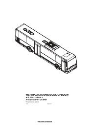
WORKSHOP MANUAL<br />
Citea CLF PR - ND Euro 4/5/EEV<br />
Main group 4<br />
1026 DD018400
Citea CLF PR - ND Euro 4/5/EEV<br />
Foreword<br />
This workshop manual contains all the relevant<br />
information to help when tracing and solving technical<br />
problems, when making adjustments and when carrying<br />
out repair work.<br />
The book contains diagrams, system descriptions, fault<br />
finding instructions and work instructions.<br />
It also contains safety regulations, which must be strictly<br />
observed.<br />
Experienced mechanics<br />
The technical information and the explanations of the<br />
repair work stated in this workshop manual have been<br />
compiled with the utmost care.<br />
Whilst compiling this workshop manual, it has been<br />
assumed that the mechanic has the necessary<br />
experience and has had the required education or<br />
training to be able to carry out the work in a responsible<br />
and safe manner.<br />
Vehicle type<br />
The information in this workshop manual has been<br />
updated until the time of printing and only concerns the<br />
following series of vehicles:<br />
Citea CLF 120-255<br />
Citea CLF 120-310<br />
This vehicle series is indicated as "Citea CLF PR - ND<br />
Euro 4/5/EEV" in this workshop manual.<br />
The letters PR indicate that this workshop manual relates<br />
to the 9.2 litre PR engine of DAF / PACCAR.<br />
The letters ND are an abbreviation of Normal Duty.<br />
Euro 4/5/EEV indicates that this workshop manual<br />
contains guidelines for the engines which are in<br />
accordance with the Euro 4, Euro 5 and EEV emission<br />
requirements.<br />
1026
Citea CLF PR - ND Euro 4/5/EEV<br />
CONTENTS<br />
Technical information<br />
1026<br />
Engine – general information ...................... 1-1<br />
General information ........................................ 1-1<br />
Specifications and adjustment information ..... 1-2<br />
Fuel system ................................................... 2-1<br />
General information ........................................ 2-1<br />
Tightening torques .......................................... 2-3<br />
Intake/exhaust system.................................. 3-1<br />
General information ........................................ 3-1<br />
Tightening torques .......................................... 3-2<br />
Throttle control ............................................. 4-1<br />
General information ........................................ 4-1<br />
Diagnosis<br />
Traction problems......................................... 1-1<br />
Traction problems ........................................... 1-1<br />
Fuel system ................................................... 2-1<br />
Introduction ..................................................... 2-1<br />
Fault finding tables.......................................... 2-2<br />
Intake/exhaust system.................................. 3-1<br />
Introduction ..................................................... 3-1<br />
Fault finding tables.......................................... 3-2<br />
Throttle control ............................................. 4-1<br />
Introduction ..................................................... 4-1<br />
Fault finding tables.......................................... 4-2<br />
Engine error codes ....................................... 5-1<br />
General information ........................................ 5-1<br />
Fuel system<br />
Safety instructions........................................ 1-1<br />
Areas of risk .................................................... 1-1<br />
General information...................................... 2-1<br />
Location of components.................................. 2-1<br />
<strong>System</strong> description.......................................... 2-3<br />
Component description................................ 3-1<br />
Fuel tanks ....................................................... 3-1<br />
Fuel level sensor............................................. 3-2<br />
Fuel level control valve ................................... 3-3<br />
Tank aeration unit ........................................... 3-3<br />
Engine preliminary fuel filter/water separator.. 3-4<br />
Engine fuel filter .............................................. 3-5<br />
Inspection and adjustment .......................... 4-1<br />
Inspecting the fuel tank level control valve ..... 4-1<br />
Bleeding the fuel system................................. 4-2<br />
Removal and installation.............................. 5-1<br />
Removing and installing the battery terminal<br />
clamps............................................................. 5-1<br />
Removing and installing the fuel tank ............. 5-3<br />
Removing and installing the AdBlue tank ........5-5<br />
Removing and installing the suction<br />
unit/fuel level gauge.........................................5-8<br />
Removing and installing the AdBlue<br />
suction unit/level gauge .................................5-11<br />
Cleaning .........................................................6-1<br />
Cleaning the fuel gauge sieve .........................6-1<br />
Cleaning the AdBlue-tank supply filter sieve ...6-3<br />
Intake/exhaust system<br />
Safety instructions ........................................1-1<br />
Safety instructions ...........................................1-1<br />
General information ......................................2-1<br />
Location of components ..................................2-1<br />
<strong>System</strong> description ..........................................2-5<br />
Component description ................................3-1<br />
EAS unit...........................................................3-1<br />
Air filter/oil separator........................................3-3<br />
Dosing unit.......................................................3-4<br />
AdBlue injection nozzle ...................................3-5<br />
Tank module....................................................3-6<br />
Exhaust gas temperature sensor before the<br />
catalytic convertor............................................3-7<br />
Exhaust gas temperature sensor after the<br />
catalytic converter............................................3-7<br />
NOx sensor......................................................3-8<br />
Catalytic convertors .........................................3-9<br />
Soot filter .......................................................3-11<br />
SMF soot filter element..................................3-13<br />
Oxidation catalytic converter .........................3-14<br />
Turbo compressor with wastegate.................3-15<br />
Cyclone filter..................................................3-16<br />
Inspection and adjustment ...........................4-1<br />
Inspecting the turbo compressor's wastegate .4-1<br />
Checking the turbo compressor’s<br />
bearing play .....................................................4-2<br />
Inspecting the air filter blockage indicator .......4-3<br />
Inspecting the air intake system ......................4-4<br />
Inspecting the exhaust system ........................4-6<br />
Inspecting the exhaust gas temperature<br />
sensor..............................................................4-8<br />
Inspecting the exhaust gas back pressure ......4-9<br />
Inspecting the emission after-treatment<br />
system ...........................................................4-16<br />
Removal and installation ..............................5-1<br />
Removing and installing the battery terminal<br />
clamps .............................................................5-1<br />
Removing and installing the turbo compressor5-3<br />
Removing and installing the intercooler unit....5-6<br />
Removing and installing the air filter element..5-8<br />
Removing and installing the catalytic<br />
convertor/silencer ............................................5-9<br />
Removing and installing a closed<br />
soot filter (DPF) .............................................5-11<br />
DD018400<br />
0<br />
1<br />
2<br />
3<br />
4
CONTENTS<br />
Citea CLF PR - ND Euro 4/5/EEV<br />
0<br />
1<br />
2<br />
3<br />
4<br />
Removing and installing the EAS system’s<br />
air filter/oil separator ..................................... 5-14<br />
Removing and installing the AdBlue filter<br />
element + EAS system’s preliminary filter..... 5-16<br />
Removing and installing the AdBlue injector. 5-19<br />
Removing and installing the exhaust gas<br />
temperature sensor....................................... 5-21<br />
Removing and installing the NOx-sensor...... 5-23<br />
Removing and installing the soot filter .......... 5-25<br />
Removing and installing the AdBlue<br />
dosing unit..................................................... 5-29<br />
Removing and installing the EAS unit........... 5-30<br />
Cleaning......................................................... 6-1<br />
Cleaning the AdBlue injector........................... 6-1<br />
Cleaning the radiator, the oil cooler and the<br />
intercooler element ......................................... 6-2<br />
Cleaning the soot filter .................................... 6-4<br />
Throttle control<br />
Safety instructions........................................ 1-1<br />
Safety instructions........................................... 1-1<br />
General information...................................... 2-1<br />
Location of components.................................. 2-1<br />
<strong>System</strong> description.......................................... 2-2<br />
Component description................................ 3-1<br />
Engine's electronic unit (DMCI)....................... 3-1<br />
Accelerator pedal sensor ................................ 3-2<br />
Control if the accelerator pedal sensor is not<br />
functioning....................................................... 3-3<br />
Inspection and adjustment .......................... 4-1<br />
Adjusting the accelerator pedal....................... 4-1<br />
DD018400<br />
1026
Citea CLF PR - ND Euro 4/5/EEV<br />
Disclaimers<br />
© 1026 <strong>VDL</strong> <strong>Bus</strong> & <strong>Coach</strong> bv, Valkenswaard,<br />
The Netherlands.<br />
0<br />
In the interest of continuous product development <strong>VDL</strong><br />
<strong>Bus</strong> & <strong>Coach</strong> reserves the right to change specifications<br />
or products at any time without prior notice.<br />
No part of this publication may be reproduced and/or<br />
published by printing, by photocopying, in digital format<br />
or in any way whatsoever without the prior consent in<br />
writing of <strong>VDL</strong> <strong>Bus</strong> & <strong>Coach</strong>.<br />
This manual shall be governed by and applied in<br />
accordance with the laws of the Netherlands.<br />
Any dispute here under shall be referred to the decision<br />
of the District Court of ’s-Hertogenbosch in the<br />
Netherlands<br />
Next remark is relevant if the text has been translated for<br />
your convenience from the English original into an other<br />
language.<br />
A translation, however, can have the consequence that<br />
differences of interpretation arise with respect to the<br />
content and meaning of the text.<br />
In all cases, therefore, the English version of this<br />
document will be regarded exclusively as the single and<br />
authentic source to establish the content and the<br />
meaning of the text in case of a dispute.<br />
3 - 3
Citea CLF PR - ND Euro 4/5/EEV<br />
0<br />
3 - 4
4<br />
Citea CLF PR - ND Euro 4/5/EEV<br />
TECHNICAL INFORMATION<br />
TECHNICAL INFORMATION<br />
0<br />
1026
TECHNICAL INFORMATION<br />
4<br />
Citea CLF PR - ND Euro 4/5/EEV<br />
0<br />
1026
4<br />
Citea CLF PR - ND Euro 4/5/EEV<br />
TECHNICAL INFORMATION<br />
Engine – general information<br />
1. ENGINE – GENERAL INFORMATION<br />
1.1 GENERAL INFORMATION<br />
0<br />
A COLD and WARM engine are define as follows:<br />
COLD engine<br />
An engine which has cooled down for at least six hours after<br />
having been at the operating temperature.<br />
WARM engine<br />
An engine which has stood still for no more than thirty<br />
minutes after having been at the operating temperature.<br />
Engine’s direction of rotation<br />
The engine’s direction of rotation is clockwise, as viewed<br />
from the same side of the engine as the vibration damper.<br />
Engine’s first cylinder<br />
The engine’s first cylinder is the cylinder located on the<br />
engine’s vibration damper.<br />
Left-hand and right-hand side of the engine<br />
The right-hand side of the engine is the side where the DMCI<br />
electronic unit is located.<br />
The left-hand side of the engine is the side where the turbo<br />
compressor is located.<br />
Engine identification by means of the engine number<br />
The engine number is located in two places on<br />
the engine:<br />
– On the engine identification plate, which is fitted against the<br />
engine’s inlet manifold.<br />
ILAj0559<br />
– Stamped on the engine block at the same height as the<br />
generator.<br />
ILAj0518<br />
1026<br />
1 - 1
TECHNICAL INFORMATION<br />
Engine – general information<br />
4<br />
Citea CLF PR - ND Euro 4/5/EEV<br />
0<br />
1.2 SPECIFICATIONS AND ADJUSTMENT<br />
INFORMATION<br />
1.2.1 ENGINE<br />
Manufacturer<br />
DAF<br />
Type<br />
PR<br />
Environmental standard<br />
Euro 4/5/EEV<br />
Engine management system<br />
DMCI<br />
No. of cylinders and cylinder configuration<br />
6 in line, vertical<br />
Valves<br />
4 per cylinder<br />
Bore x stroke<br />
118 x 140 mm<br />
Cylinder volume<br />
9.2 litres<br />
Compression ratio 17,4 : 1<br />
Fuel injection<br />
Direct<br />
Injection sequence 1-5-3-6-2-4<br />
Air intake system<br />
Turbo intercooling<br />
Cooling<br />
Liquid<br />
Weight<br />
Approx. 900 kg<br />
Injection pressure<br />
Minimum 225 bar<br />
Max. 1,750 bar<br />
Type Power (kw (pk)/<br />
rpm)<br />
Torque (Nm/<br />
rpm)<br />
PR183 183 (249) / 2200 1050 / 1100 - 1700<br />
PR228 228 (310) / 2200 1275 / 1100 - 1700<br />
PR265 265 (360) / 2200 1450 / 1100 - 1700<br />
1.2.2 VALVE CLEARANCE 1<br />
Valve clearance (cold 2 /warm 3 )<br />
Inlet<br />
Outlet<br />
0.50 mm<br />
0.50 mm<br />
1. Always see https://eportal.daf.com for the up-to-date, applicable<br />
adjustment sizes<br />
2. Cold: an engine which has cooled down for at least six hours after having<br />
been at the operating temperature.<br />
3. Warm: an engine which has stood still for no more than thirty minutes<br />
after having been at the operating temperature.<br />
1 - 2 1026
4<br />
Citea CLF PR - ND Euro 4/5/EEV<br />
TECHNICAL INFORMATION<br />
Fuel system<br />
2. FUEL SYSTEM<br />
2.1 GENERAL INFORMATION<br />
0<br />
Fuel system<br />
Idling engine speed<br />
Max. controlled engine speed<br />
(unloaded)<br />
600 ± 25 rpm<br />
2,200 ± 25 rpm<br />
Fuel level gauge (fuel tank supply unit)<br />
Vacuum pressure valve<br />
0,01 < P 0.02 bar<br />
Pressure relief valve<br />
0,16 < P < 0.20 bar<br />
Fuel level element<br />
Fuel level sensor resistance value L = 400 mm<br />
Length H (mm) Resistance (Ω)<br />
>328 10<br />
328 43<br />
307 76<br />
286 109<br />
265 142<br />
244 178<br />
223 214<br />
202 250<br />
181 286<br />
160 322<br />
139 358<br />
118 394<br />
97 430<br />
76 466<br />
55 502<br />
Fuel tanks<br />
Volume left-hand tank<br />
Volume right-hand tank<br />
175 litres<br />
140 litres<br />
ILAh0157<br />
1026<br />
2 - 1
TECHNICAL INFORMATION<br />
Fuel system<br />
4<br />
Citea CLF PR - ND Euro 4/5/EEV<br />
0<br />
AdBlue level element<br />
Sensor type<br />
AdBlue level sensor type<br />
AdBlue temperature sensor<br />
type<br />
Level/Temperature<br />
Reed switch in combination with<br />
resistances<br />
NTC<br />
1. AdBlue level sensor earth<br />
2. AdBlue level sensor signal<br />
3. AdBlue temperature sensor earth<br />
4. AdBlue temperature sensor signal<br />
AdBlue temperature sensor resistance value 1,000 Ohm (± 5%) at 25° C<br />
AdBlue level sensor resistance value L = 385<br />
Length H (mm) Resistance (Ω)<br />
>307 120<br />
307 211<br />
286 302<br />
265 422<br />
244 542<br />
223 692<br />
202 842<br />
181 1022<br />
160 1412<br />
139 1882<br />
118 2392<br />
97 2952<br />
76 5652<br />
55 9552<br />
AdBlue tank<br />
Volume<br />
Approx. 30 litres<br />
For further technical information concerning the fuel system,<br />
see https://eportal.daf.com.<br />
ILAh0156<br />
2 - 2 1026
4<br />
Citea CLF PR - ND Euro 4/5/EEV<br />
TECHNICAL INFORMATION<br />
Fuel system<br />
2.2 TIGHTENING TORQUES<br />
The tightening torques stated in this chapter deviate from the<br />
standard tightening torques given in the standard tightening<br />
torques overview.<br />
The threaded connections which are not stated here must,<br />
therefore, be tightened to the torque given in the summary of<br />
the standard tightening torques.<br />
If any attachment aids (attachment nuts and bolts) are<br />
replaced, it is very important that the new attachment aids<br />
are exactly the same length and quality as those being<br />
replaced, unless otherwise stated.<br />
0<br />
Fuel system<br />
Fuel filter screw cap<br />
40 Nm<br />
Fuel level gauge<br />
A. Plug 2 - 3 Nm<br />
B. Plug 2 - 3 Nm<br />
C. Fuel tank supply 20 Nm<br />
D. Fuel tank return 20 Nm<br />
E. Bleed unit 2 - 3 Nm<br />
Assembly<br />
Compression force<br />
Torque (30° clockwise)<br />
↓ 30 - 40 kg<br />
↵ max. 50 Nm<br />
ILAf0006<br />
EAS system<br />
EAS unit attachment bolt<br />
AdBlue injection nozzle lock nut<br />
AdBlue line hexagonal nut<br />
EAS air filter<br />
AdBlue filter element screw cap<br />
EAS unit drain plug<br />
EAS unit preliminary filter<br />
AdBlue tank drain plug<br />
Exhaust gas back pressure measurement<br />
plug (M14 x 1.5)<br />
24 Nm<br />
..... Nm<br />
31 ± 1 Nm<br />
3/4 - 1 revolution after touching the sealing ring<br />
25 Nm<br />
4 Nm<br />
0.4 ± 0.1 Nm<br />
90 ± 10 Nm<br />
30 Nm<br />
For the other fuel system tightening torques, see https://<br />
eportal.daf.com.<br />
1026<br />
2 - 3
TECHNICAL INFORMATION<br />
Fuel system<br />
4<br />
Citea CLF PR - ND Euro 4/5/EEV<br />
0 Battery terminal clamp A Battery terminal clamp a<br />
12 ± 2 Nm<br />
B Battery terminal clamp a + 40 ± 4 Nm<br />
C Battery terminal clamp a - 12 ± 2 Nm<br />
D Battery terminal clamp a - 30 ± 4 Nm<br />
a. To prevent corrosion, lubricate the outside of the connections with acidfree<br />
Vaseline.<br />
ILAh0338<br />
2 - 4 1026
4<br />
Citea CLF PR - ND Euro 4/5/EEV<br />
TECHNICAL INFORMATION<br />
Intake/exhaust system<br />
3. INTAKE/EXHAUST SYSTEM<br />
3.1 GENERAL INFORMATION<br />
0<br />
Exhaust gas back pressure (for maximum loaded engine<br />
speed)<br />
Engine<br />
type<br />
Layout<br />
Max. full load<br />
value (mbar) a<br />
PR 183 SCR 140<br />
SCR + DPF<br />
Engine<br />
type<br />
Layout<br />
Max. full load<br />
value (mbar) a<br />
PR 228 SCR 140<br />
SCR + DPF<br />
a. Measured at the operating temperature, under full load at 2,200 rpm<br />
K value for the soot emission<br />
The K value (m -1 ) for the soot measurement is given in the<br />
bottom right-hand corner of the engine’s type plate.<br />
Engine Layout K value (m -1 )<br />
type<br />
PR 183 U1 0,58<br />
U2 0,58<br />
Engine Layout K value (m -1 )<br />
type<br />
PR 228 U1 0,57<br />
U2 0,57<br />
ILAj0484<br />
Turbo compressor<br />
Control rod movement at 1.83 bar<br />
Axial bearing play<br />
Radial bearing play<br />
0.3 - 1.3 mm<br />
0.025 - 0.127 mm<br />
0.326 - 0.508 mm<br />
For the other technical information concerning the intake/<br />
exhaust system, see https://eportal.daf.com.<br />
1026<br />
3 - 1
TECHNICAL INFORMATION<br />
Intake/exhaust system<br />
4<br />
Citea CLF PR - ND Euro 4/5/EEV<br />
0<br />
3.2 TIGHTENING TORQUES<br />
The tightening torques stated in this chapter deviate from the<br />
standard tightening torques given in the standard tightening<br />
torques overview.<br />
The threaded connections which are not stated here must,<br />
therefore, be tightened to the torque given in the summary of<br />
the standard tightening torques.<br />
If any attachment aids (attachment nuts and bolts) are<br />
replaced, it is very important that the new attachment aids<br />
are exactly the same length and quality as those being<br />
replaced, unless otherwise stated.<br />
Turbo compressor<br />
Attachment bolts<br />
Banjo bolt M22<br />
Attachment bolts M8<br />
Flexible pipe<br />
45 Nm<br />
105 Nm<br />
30 Nm<br />
30 Nm<br />
Soot filter<br />
Soot filter V-clamping straps<br />
Clamping strap lock nut<br />
15 Nm ab<br />
15 Nm<br />
a. Tighten the V-clamping straps to the specified torque. Tap the edge of<br />
the clamping strap with a plastic hammer. Retighten the clamping<br />
straps to the specified torque.<br />
b. Evenly tighten the clamping straps in a number of phases.<br />
ILAj0678<br />
3 - 2 1026
4<br />
Citea CLF PR - ND Euro 4/5/EEV<br />
TECHNICAL INFORMATION<br />
Intake/exhaust system<br />
Exhaust gas temperature sensor<br />
Cap nut<br />
30 ± 15 Nm<br />
0<br />
NOx sensor<br />
Attachment nut<br />
50 ± 10 Nm<br />
AdBlue dosing unit<br />
AdBlue hose hexagonal nut<br />
EAS unit<br />
Attachment bolts<br />
31 ± 1 Nm<br />
24 Nm<br />
Hose clamps<br />
A. Torro Normaclamp 5 Nm<br />
B. “GBS” M Norma clamp 20 Nm<br />
C. Normaconnect 117 7 Nm<br />
D. Breeze HKE 12 Nm<br />
E. Breeze Torca B9222 7.5 Nm<br />
For the other intake/exhaust system tightening torques, see<br />
https://eportal.daf.com.<br />
ILAj0430<br />
1026<br />
3 - 3
TECHNICAL INFORMATION<br />
Intake/exhaust system<br />
4<br />
Citea CLF PR - ND Euro 4/5/EEV<br />
0<br />
3 - 4 1026
4<br />
Citea CLF PR - ND Euro 4/5/EEV<br />
TECHNICAL INFORMATION<br />
Throttle control<br />
4. THROTTLE CONTROL<br />
4.1 GENERAL INFORMATION<br />
0<br />
Accelerator pedal sensor<br />
Supply voltage potentiometer a<br />
Potentiometer voltage (between ports 2 and 5)<br />
Potentiometer voltage (between ports 3 and 5), not depressed<br />
Potentiometer voltage (between ports 3 and 5), depressed to the kick-down position<br />
Potentiometer voltage (between ports 3 and 5), kick-down position<br />
Approx. 5 V<br />
Approx. 5 V<br />
Approx. 0.39 V<br />
Approx. 3.15 V<br />
Approx. 3.71 V<br />
Potentiometer resistance (between ports 2 and 5)<br />
Potentiometer resistance (between ports 3 and 5), not depressed<br />
Potentiometer resistance (between ports 3 and 5), depressed to the kick-down position<br />
Potentiometer resistance (between ports 3 and 5), kick-down position<br />
a. Measured with an open connection<br />
Approx. 1 kOhm<br />
Approx. 1.16 kOhm<br />
Approx. 1.74 kOhm<br />
Approx. 1.86 kOhm<br />
ILAj0287<br />
1026<br />
4 - 1
TECHNICAL INFORMATION<br />
Throttle control<br />
4<br />
Citea CLF PR - ND Euro 4/5/EEV<br />
0 Accelerator pedal electrical values<br />
Function<br />
Kick-down<br />
switch (KD)<br />
Safety switch<br />
(SK)<br />
Type of<br />
switch<br />
Closer<br />
contact<br />
Closer<br />
contact<br />
Indication<br />
Accelerator pedal mechanical values<br />
Tightening<br />
angle<br />
S2 74° ± 3°<br />
S1 9° ± 3°<br />
Function Indication Tightening Voltage<br />
angle<br />
Kick-down T1 70° +1/-2° 0.66<br />
switch (KD)<br />
Mechanical T2 88° 0.813<br />
stop<br />
Idling (LL) - 0° 0.08<br />
ILAj0288<br />
4 - 2 1026
4<br />
Citea CLF PR - ND Euro 4/5/EEV<br />
DIAGNOSIS<br />
DIAGNOSIS<br />
1<br />
1026
DIAGNOSIS<br />
4<br />
Citea CLF PR - ND Euro 4/5/EEV<br />
1<br />
1026
4<br />
Citea CLF PR - ND Euro 4/5/EEV<br />
DIAGNOSIS<br />
Traction problems<br />
1. TRACTION PROBLEMS<br />
1.1 TRACTION PROBLEMS<br />
The first test that must be performed when investigating<br />
traction problems is the acceleration test. Contact <strong>VDL</strong> <strong>Bus</strong><br />
& <strong>Coach</strong> for more information.<br />
1<br />
1026<br />
1 - 1
DIAGNOSIS<br />
Traction problems<br />
4<br />
Citea CLF PR - ND Euro 4/5/EEV<br />
1<br />
1 - 2 1026
4<br />
Citea CLF PR - ND Euro 4/5/EEV<br />
DIAGNOSIS<br />
Fuel system<br />
2. FUEL SYSTEM<br />
2.1 INTRODUCTION<br />
If there is a fault in the system, then, in most cases, this fault<br />
will be detected by the electronic unit in the form of an error<br />
code. This error code can be read with the aid of diagnosis<br />
equipment or a flash code. Possible causes of symptoms<br />
that are not detected by the electronic unit are given in the<br />
fault finding tables.<br />
1<br />
Comment<br />
See https://eportal.daf.com for detailed fault finding tables<br />
and error code tables.<br />
1026<br />
2 - 1
DIAGNOSIS<br />
Fuel system<br />
4<br />
Citea CLF PR - ND Euro 4/5/EEV<br />
1<br />
2.2 FAULT FINDING TABLES<br />
THE STARTER TURNS THE ENGINE OVER BUT THE<br />
ENGINE DOES NOT START<br />
Possible cause<br />
There is air in the fuel system.<br />
The fuel filter is blocked.<br />
No fuel supply/the fuel supply pump is faulty, no delivery.<br />
The fuel pressure control valve remains open.<br />
Poor fuel quality.<br />
Remedy<br />
Check whether any air is drawn in. Pay particular<br />
attention to the suction line and the oil seal for the fuel<br />
delivery pump.<br />
Bleed the fuel system.<br />
Replace the fuel filter and clean the system.<br />
Check the fuel level.<br />
Check the lines for blockages and leaks.<br />
Check the fuel supply pump.<br />
Check the gallery pressure.<br />
Check the gallery pressure.<br />
Drain the fuel, rinse the fuel system, replace the fuel<br />
filters and fill the fuel tank with fuel.<br />
THE ENGINE STALLS, BUT RUNS AGAIN AFTER IT HAS<br />
BEEN RESTARTED<br />
Possible cause<br />
There is air in the fuel system.<br />
The fuel pressure control valve remains open.<br />
Remedy<br />
Check whether any air is drawn in. Pay particular<br />
attention to the suction line and the oil seal for the fuel<br />
delivery pump.<br />
Bleed the fuel system.<br />
Check the gallery pressure.<br />
THE ENGINE IS DIFFICULT TO START<br />
Possible cause<br />
There is air in the fuel system.<br />
The fuel pressure control valve remains open.<br />
The fuel supply pump’s delivery is too small.<br />
The fuel filter is blocked.<br />
There is a fuel leak between the injector line and the<br />
injector.<br />
Poor fuel quality.<br />
There is a mechanical fault with the pump unit or it is<br />
blocked.<br />
There is a mechanical fault with the injector or it is<br />
blocked.<br />
Remedy<br />
Check whether any air is drawn in.<br />
Bleed the fuel system.<br />
Check the gallery pressure.<br />
Check the fuel supply pump and, if necessary, replace it.<br />
Check the gallery pressure.<br />
Replace the fuel filter and clean the system.<br />
Check around the injector for fuel leaks.<br />
If necessary, replace the injector line.<br />
Drain the fuel, rinse the fuel system, replace the fuel<br />
filters and fill the fuel tank with fuel.<br />
Check the operation of the pump unit.<br />
Check the operation of the injector.<br />
2 - 2 1026
4<br />
Citea CLF PR - ND Euro 4/5/EEV<br />
DIAGNOSIS<br />
Fuel system<br />
THE ENGINE IDLES (TOO FAST) AND DOES NOT REACT<br />
TO THE ACCELERATOR PEDAL<br />
Possible cause<br />
There is a mechanical fault with the accelerator pedal<br />
sensor.<br />
Remedy<br />
Check:<br />
- The mechanical connection of the sensor/accelerator<br />
pedal.<br />
- The accelerator pedal.<br />
1<br />
DIESEL KNOCK DURING ACCELERATION<br />
Possible cause<br />
There is air in the fuel system.<br />
Poor fuel quality.<br />
There is a mechanical fault with the pump unit(s).<br />
There is a mechanical fault with the injector(s).<br />
Remedy<br />
Check whether any air is drawn in. Pay particular<br />
attention to the suction line and the oil seal for the fuel<br />
delivery pump.<br />
Bleed the fuel system.<br />
Drain the fuel, rinse the fuel system, replace the fuel<br />
filters and fill the fuel tank with fuel.<br />
Check the operation of the pump unit(s).<br />
Check the operation of the injector(s).<br />
THE ENGINE RUNS ERRATICALLY<br />
Possible cause<br />
There is air in the fuel system.<br />
The fuel pressure control valve remains open.<br />
The fuel filter is blocked.<br />
There is a fuel leak between the injector line(s) and the<br />
injector(s).<br />
Poor fuel quality.<br />
The fuel supply pump’s delivery is too small.<br />
There is a mechanical fault with the pump unit(s) or it/<br />
they is/are blocked.<br />
There is a mechanical fault with the injector(s).<br />
Incorrectly programmed pump unit(s)/injector(s).<br />
Remedy<br />
Check whether any air is drawn in. Pay particular<br />
attention to the suction line and the oil seal for the fuel<br />
delivery pump.<br />
Bleed the fuel system.<br />
Check the gallery pressure.<br />
Replace the fuel filter and clean the system.<br />
Check around the injector(s) for fuel leaks and, if<br />
necessary, replace the injector line(s).<br />
Drain the fuel, rinse the fuel system, replace the fuel<br />
filters and fill the fuel tank with fuel.<br />
Check the fuel supply pump and the gallery pressure.<br />
Check the operation of the pump unit(s).<br />
Check the operation of the injector(s).<br />
Check the calibration codes and, if necessary,<br />
reprogram them.<br />
REDUCED ENGINE POWER AT ALL ENGINE SPEEDS<br />
Possible cause<br />
The fuel filter is blocked.<br />
There is air in the fuel system.<br />
The fuel pressure control valve remains open.<br />
The fuel supply pump’s delivery is too small.<br />
Remedy<br />
Replace the fuel filter and clean the system.<br />
Check whether any air is drawn in. Pay particular<br />
attention to the suction line and the oil seal for the fuel<br />
delivery pump.<br />
Bleed the fuel system.<br />
Check the gallery pressure.<br />
Check the fuel supply pump and the gallery pressure.<br />
1026<br />
2 - 3
DIAGNOSIS<br />
Fuel system<br />
4<br />
Citea CLF PR - ND Euro 4/5/EEV<br />
1<br />
Poor fuel quality.<br />
Possible cause<br />
There is a fuel leak between the injector line(s) and the<br />
injector(s).<br />
There is a mechanical fault with the pump unit(s) or it/<br />
they is/are blocked.<br />
There is a mechanical fault with the injector(s).<br />
Remedy<br />
Drain the fuel, rinse the fuel system, replace the fuel<br />
filters and fill the fuel tank with fuel.<br />
Check around the injector(s) for fuel leaks and, if<br />
necessary, replace the injector line(s).<br />
Check the operation of the pump unit(s).<br />
Check the operation of the injector(s).<br />
THE ENGINE STOPS DURING ACCELERATION OR<br />
WHEN UNDER A HEAVY LOAD<br />
Possible cause<br />
There is an internal fuel leak between the fuel delivery<br />
pipe(s) and the injector(s).<br />
Not enough fuel supplied by the high-pressure pump or<br />
the fuel delivery pump.<br />
Remedy<br />
Check the quantity of return fuel.<br />
Check:<br />
- The high-pressure pump.<br />
- The fuel delivery pump.<br />
REDUCED POWER AT ALL ENGINE SPEEDS<br />
Possible cause<br />
The fuel fine filter is blocked.<br />
The fuel pressure control valve remains open.<br />
The fuel supply pump’s delivery is too small.<br />
Poor fuel quality.<br />
There is a fuel leak between the injector line(s) and the<br />
injector(s).<br />
There is a mechanical fault with the pump unit(s) or it/<br />
they is/are blocked.<br />
There is a mechanical fault with the injector(s).<br />
Remedy<br />
Replace the fuel filter and clean the system.<br />
Check the gallery pressure.<br />
Check the fuel supply pump and the gallery pressure.<br />
Drain the fuel, rinse the fuel system, replace the fuel<br />
filters and fill the fuel tank with fuel.<br />
Check around the injector(s) for fuel leaks and, if<br />
necessary, replace the injector line(s).<br />
Check the operation of the pump unit(s).<br />
Check the operation of the injector(s).<br />
BLACK SMOKE DEVELOPMENT<br />
Possible cause<br />
Incorrectly programmed pump unit(s)/injector(s).<br />
There is a mechanical fault with the pump unit(s).<br />
There is a mechanical fault with the injector(s).<br />
Remedy<br />
Check the calibration codes and, if necessary,<br />
reprogram them.<br />
Check the operation of the pump unit(s).<br />
Check the operation of the injector(s).<br />
THE ENGINE OVERHEATS<br />
Poor fuel quality.<br />
Possible cause<br />
Remedy<br />
Drain the fuel, rinse the fuel system, replace the fuel<br />
filters and fill the fuel tank with the specified fuel.<br />
TOO HIGH FUEL CONSUMPTION<br />
Poor fuel quality.<br />
Possible cause<br />
Remedy<br />
Drain the fuel, rinse the fuel system, replace the fuel<br />
filters and fill the fuel tank with the specified fuel.<br />
2 - 4 1026
4<br />
Citea CLF PR - ND Euro 4/5/EEV<br />
DIAGNOSIS<br />
Fuel system<br />
Possible cause<br />
The fuel fine filter/fuel coarse filter is blocked.<br />
There is a mechanical fault with the injector(s) or it/they<br />
is/are blocked.<br />
The fuel system leaks.<br />
REDUCED MAXIMUM ENGINE SPEED<br />
Possible cause<br />
There is air in the fuel system.<br />
The fuel fine filter/fuel coarse filter is blocked.<br />
There is a mechanical fault with the injector(s) or it/they<br />
is/are blocked.<br />
Not enough fuel supplied by the high-pressure pump or<br />
the fuel delivery pump.<br />
Replace the fuel fine filter and clean the system.<br />
Replace the injectors.<br />
Check for leaks.<br />
Remedy<br />
Remedy<br />
Check whether any air is drawn in:<br />
- Via the suction line.<br />
Replace the fuel fine filter and clean the system.<br />
Replace the injectors.<br />
Check:<br />
- The high-pressure pump.<br />
- The fuel delivery pump.<br />
1<br />
1026<br />
2 - 5
DIAGNOSIS<br />
Fuel system<br />
4<br />
Citea CLF PR - ND Euro 4/5/EEV<br />
1<br />
2 - 6 1026
4<br />
Citea CLF PR - ND Euro 4/5/EEV<br />
DIAGNOSIS<br />
Intake/exhaust system<br />
3. INTAKE/EXHAUST SYSTEM<br />
3.1 INTRODUCTION<br />
If there is a fault in the system, then, in most cases, this fault<br />
will be detected by the electronic unit in the form of an error<br />
code. This error code can be read with the aid of diagnosis<br />
equipment or a flash code. Possible causes of symptoms<br />
that are not detected by the electronic unit are given in the<br />
fault finding tables.<br />
1<br />
Comment<br />
See https://eportal.daf.com for detailed fault finding tables<br />
and error code tables.<br />
1026<br />
3 - 1
DIAGNOSIS<br />
Intake/exhaust system<br />
4<br />
Citea CLF PR - ND Euro 4/5/EEV<br />
1<br />
3.2 FAULT FINDING TABLES<br />
REDUCED POWER AT ALL ENGINE SPEEDS<br />
Possible cause<br />
The fuel fine filter is blocked.<br />
The fuel pressure control valve remains open.<br />
The fuel supply pump’s delivery is too small.<br />
Poor fuel quality.<br />
There is a fuel leak between the injector line(s) and the<br />
injector(s).<br />
There is a mechanical fault with the pump unit(s) or it/<br />
they is/are blocked.<br />
There is a mechanical fault with the injector(s).<br />
Remedy<br />
Replace the fuel filter and clean the system.<br />
Check the gallery pressure.<br />
Check the fuel supply pump and the gallery pressure.<br />
Drain the fuel, rinse the fuel system, replace the fuel<br />
filters and fill the fuel tank with fuel.<br />
Check around the injector(s) for fuel leaks and, if<br />
necessary, replace the injector line(s).<br />
Check the operation of the pump unit(s).<br />
Check the operation of the injector(s).<br />
REDUCED POWER ABOVE A CERTAIN ENGINE SPEED.<br />
Possible cause<br />
The fuel fine filter is partially blocked.<br />
There is a mechanical fault with the pump unit(s) or it/<br />
they is/are blocked.<br />
The gallery pressure is too low because the fuel<br />
pressure control valve remains open.<br />
The gallery pressure is too low because of a low fuel<br />
supply pump delivery.<br />
Remedy<br />
Replace the fuel filter and clean the system.<br />
Check the operation of the pump unit(s).<br />
Check the fuel pressure control valve.<br />
Check the fuel supply pump.<br />
TOO HIGH FUEL CONSUMPTION<br />
Possible cause<br />
The turbo compressor is faulty.<br />
There is an air leak in the intake system.<br />
Remedy<br />
Check the turbo compressor.<br />
Pressure-test the intake system.<br />
REDUCED MAXIMUM ENGINE SPEED<br />
Possible cause<br />
The turbo compressor is faulty.<br />
Remedy<br />
Check the turbo compressor.<br />
FLUCTUATING TURBOCHARGER NOISES<br />
Possible cause<br />
Blocked air inlet to the turbo compressor.<br />
The compressor side of the turbo compressor is<br />
contaminated.<br />
The turbo compressor is damaged.<br />
Remedy<br />
Check the air inlet and remove any blockages.<br />
Clean the compressor side with a non-corrosive cleaning<br />
product or a soft brush.<br />
Check the inlet side for carbon deposits and other<br />
contamination.<br />
Replace the turbo compressor and trace the cause.<br />
3 - 2 1026
4<br />
Citea CLF PR - ND Euro 4/5/EEV<br />
DIAGNOSIS<br />
Intake/exhaust system<br />
THE ENGINE EMITS BLACK SMOKE<br />
Possible cause<br />
The air filter element is blocked.<br />
Air leak between the turbo compressor and the inlet<br />
manifold.<br />
There is an air leak between the inlet manifold and the<br />
cylinder head.<br />
The compressor side of the turbo compressor is<br />
contaminated.<br />
Gas leak between the exhaust manifold and the cylinder<br />
head.<br />
Gas leak between the exhaust manifold and the turbo<br />
compressor.<br />
The turbo compressor is damaged.<br />
Remedy<br />
Replace the air filter element.<br />
Check the hoses and pressure-test the intake section.<br />
Check for leaks. If necessary, replace the gaskets.<br />
Clean the compressor side with a non-corrosive cleaning<br />
product or a soft brush.<br />
Check the inlet side for carbon deposits and other<br />
contamination.<br />
Check the attachment bolts and the gaskets.<br />
Check the attachment bolts and the gaskets.<br />
Replace the turbo compressor and trace the cause.<br />
1<br />
THE ENGINE EMITS BLUE SMOKE<br />
Possible cause<br />
The air filter element is blocked.<br />
Air leak between the turbo compressor and the inlet<br />
manifold.<br />
There is an air leak between the inlet manifold and the<br />
cylinder head.<br />
The compressor side of the turbo compressor is<br />
contaminated.<br />
The turbo compressor oil return line is blocked.<br />
The turbo compressor is damaged.<br />
Remedy<br />
Replace the air filter element.<br />
Check the hoses and pressure-test the intake section.<br />
Check for leaks. If necessary, replace the gaskets.<br />
Clean the compressor side with a non-corrosive cleaning<br />
product or a soft brush.<br />
Check the inlet side for carbon deposits and other<br />
contamination.<br />
Check the oil line. If necessary, replace it.<br />
Replace the turbo compressor and trace the cause.<br />
OIL LEAKAGE ON THE TURBINE SIDE OF THE TURBO<br />
COMPRESSOR<br />
Possible cause<br />
The compressor side of the turbo compressor is<br />
contaminated.<br />
The turbo compressor oil return line is blocked.<br />
The turbo compressor is damaged.<br />
Remedy<br />
Clean the compressor side with a non-corrosive cleaning<br />
product or a soft brush.<br />
Check the inlet side for carbon deposits and other<br />
contamination.<br />
Check the oil line. If necessary, replace it.<br />
Replace the turbo compressor and trace the cause.<br />
1026<br />
3 - 3
DIAGNOSIS<br />
Intake/exhaust system<br />
4<br />
Citea CLF PR - ND Euro 4/5/EEV<br />
1<br />
OIL LEAK ON COMPRESSOR SIDE OF THE TURBO<br />
COMPRESSOR.<br />
Possible cause<br />
The compressor side of the turbo compressor is<br />
contaminated.<br />
The turbo compressor oil line is blocked.<br />
The turbo compressor is damaged.<br />
Remedy<br />
Clean the compressor side with a non-corrosive cleaning<br />
product or a soft brush.<br />
Check the inlet side for carbon deposits and other<br />
contamination.<br />
Check the oil line. If necessary, replace it.<br />
Replace the turbo compressor and trace the cause.<br />
THE EXHAUST GAS BACK PRESSURE IS TOO HIGH<br />
Possible cause<br />
Incorrect butterfly valve setting.<br />
The butterfly valve is fitted in the wrong position.<br />
The butterfly valve is partially operated by a residual<br />
pressure in the operating cylinder.<br />
No original silencer fitted.<br />
The exhaust pipe has been squeezed closed or has<br />
been internally blocked by a loose part.<br />
The catalytic converter in the silencer is blocked.<br />
The soot filter is blocked.<br />
Remedy<br />
Check the butterfly valve’s setting.<br />
Check whether the butterfly valve has been fitted<br />
correctly.<br />
Check the operating cylinder.<br />
Check the silencer.<br />
Check the exhaust system for blockages and/or<br />
damage.<br />
Replace the silencer.<br />
Clean the soot filter (only for EEV).<br />
THE INLET UNDERPRESSURE IS TOO HIGH<br />
Possible cause<br />
The air filter element is blocked.<br />
Remedy<br />
Replace the air filter element.<br />
3 - 4 1026
4<br />
Citea CLF PR - ND Euro 4/5/EEV<br />
DIAGNOSIS<br />
Throttle control<br />
4. THROTTLE CONTROL<br />
4.1 INTRODUCTION<br />
If there is a fault in the system, then, in most cases, this fault<br />
will be detected by the electronic unit in the form of an error<br />
code. This error code can be read with the aid of diagnosis<br />
equipment or a flash code. Possible causes of symptoms<br />
that are not detected by the electronic unit are given in the<br />
fault finding tables.<br />
1<br />
1026<br />
4 - 1
DIAGNOSIS<br />
Throttle control<br />
4<br />
Citea CLF PR - ND Euro 4/5/EEV<br />
4.2 FAULT FINDING TABLES<br />
THE ENGINE IDLES (TOO FAST) AND DOES NOT REACT<br />
TO THE ACCELERATOR PEDAL<br />
1<br />
Possible cause<br />
There is a mechanical fault with the accelerator pedal<br />
sensor.<br />
Remedy<br />
Check:<br />
- The mechanical connection of the sensor/accelerator<br />
pedal.<br />
- The accelerator pedal<br />
- The accelerator pedal modulator.<br />
THE ENGINE IDLES TOO FAST (1,000 RPM) AND DOES<br />
NOT REACT TO THE ACCELERATOR PEDAL<br />
Possible cause<br />
Short circuit to earth of the idling switch in the accelerator<br />
pedal sensor.<br />
Remedy<br />
Check:<br />
- The idling switch in the accelerator pedal sensor.<br />
- The wiring.<br />
THE ENGINE IDLES TOO FAST (1,000 RPM) AND<br />
REACTS TO THE ACCELERATOR PEDAL<br />
Possible cause<br />
Accelerator pedal sensor, signal fault/short circuit/break<br />
in potentiometer connection<br />
Remedy<br />
Check:<br />
- The accelerator pedal sensor potentiometer.<br />
- The wiring.<br />
THE MAXIMUM ENGINE SPEED IS 1,000 RPM<br />
Possible cause<br />
Accelerator pedal sensor, signal fault/short circuit/break<br />
in potentiometer connection<br />
Remedy<br />
Check:<br />
- The idling switch in the accelerator pedal sensor.<br />
- The wiring.<br />
REDUCED POWER AT ALL ENGINE SPEEDS<br />
Possible cause<br />
There is a mechanical fault with the accelerator pedal<br />
sensor.<br />
Accelerator pedal sensor, signal error/short circuit/break<br />
in connection.<br />
Remedy<br />
Check:<br />
- The mechanical connection of the sensor/accelerator<br />
pedal.<br />
- The accelerator pedal.<br />
Check:<br />
- The accelerator pedal<br />
- The idling switch in the accelerator pedal sensor<br />
- The wiring.<br />
- The accelerator pedal setting.<br />
REDUCED MAXIMUM ENGINE SPEED<br />
Possible cause<br />
Short circuit to positive or there is a break in the<br />
connection for the idling switch in the accelerator pedal<br />
sensor.<br />
Remedy<br />
Check:<br />
- The idling switch in the accelerator pedal sensor.<br />
4 - 2 1026
4<br />
Citea CLF PR - ND Euro 4/5/EEV<br />
DIAGNOSIS<br />
Engine error codes<br />
5. ENGINE ERROR CODES<br />
5.1 GENERAL INFORMATION<br />
If there is a fault in the system, then, in most cases, this fault<br />
will be detected by the electronic unit in the form of an error<br />
code. This error code can be read with the aid of diagnosis<br />
equipment or a flash code.<br />
1<br />
In the fault finding tables, a description of the error code is<br />
given after the error code.<br />
For an explanation of the meaning of the error codes, see the<br />
DMCI error code list: <strong>VDL</strong> <strong>Bus</strong> & <strong>Coach</strong> document<br />
DD0193xx.<br />
For an up-to-date overview of the error codes and fault<br />
diagnosis, please refer to https://eportal.daf.com.<br />
0930<br />
5 - 1
DIAGNOSIS<br />
Engine error codes<br />
4<br />
Citea CLF PR - ND Euro 4/5/EEV<br />
1<br />
5 - 2 0930
4<br />
Citea CLF PR - ND Euro 4/5/EEV<br />
FUEL SYSTEM<br />
FUEL SYSTEM<br />
2<br />
1026
FUEL SYSTEM<br />
4<br />
Citea CLF PR - ND Euro 4/5/EEV<br />
2<br />
1026
4<br />
Citea CLF PR - ND Euro 4/5/EEV<br />
FUEL SYSTEM<br />
Safety instructions<br />
1. SAFETY INSTRUCTIONS<br />
1.1 AREAS OF RISK<br />
1.1.1 MOVING PARTS<br />
Remain a safe distance from rotating and/or moving<br />
components.<br />
1.1.2 ELECTRICAL SHORT CIRCUIT<br />
2<br />
It is recommended to always disconnect the earth cable from<br />
the battery when carrying out work that does not require the<br />
vehicle to have an electrical power source.<br />
1.1.3 VARIOUS LIQUIDS<br />
Various types of oil and other lubricants used on the vehicle<br />
can harm your health. This also applies to engine coolant,<br />
screenwash fluid, coolant in air conditioning systems, battery<br />
acid and clutch fluid.<br />
Avoid internal and external bodily contact with these liquids.<br />
1.1.4 FUEL<br />
Diesel is an extremely flammable liquid. It<br />
must not be exposed to a naked flame or<br />
come into contact with hot components.<br />
The diesel fumes remaining in an empty<br />
fuel tank form an extremely explosive<br />
mixture.<br />
A certain quantity of fuel will be released when removing the<br />
fuel system’s components. To keep this quantity of fuel to a<br />
minimum, unscrew the tank cap to allow any excess<br />
pressure to escape.<br />
Collect any fuel that escapes and remain aware of the fire<br />
risk.<br />
1026<br />
1 - 1
FUEL SYSTEM<br />
Safety instructions<br />
4<br />
Citea CLF PR - ND Euro 4/5/EEV<br />
1.1.5 ADBLUE<br />
See the AdBlue safety data sheet for the<br />
properties, risks and safety information.<br />
Always wear gloves and safety goggles<br />
when working on the AdBlue unit/<br />
exhaust gas after-treatment system.<br />
2<br />
AdBlue is non-inflammable. If AdBlue is exposed to high<br />
temperatures, the solution breaks down into ammonia and<br />
carbon dioxide.<br />
Although AdBlue is not poisonous and not harmful to<br />
the environment, collect AdBlue separately.<br />
Avoid AdBlue coming into contact with painted components.<br />
Spilt AdBlue can be easily removed with water. If AdBlue<br />
dries, it leaves a white film, which can be removed with<br />
water.<br />
AdBlue corrodes metals, such as copper and aluminium.<br />
Alloys, such as brass, can also be damaged.<br />
If AdBlue comes into contact with the electrical installation<br />
(wiring harnesses and contacts), then the components<br />
concerned must be replaced.<br />
Do not allow AdBlue to come into contact with other<br />
chemicals.<br />
Carefully check the AdBlue lines for leaks.<br />
Avoid bodily contact with AdBlue.<br />
• In the event of skin contact: rinse with plenty of water.<br />
• In the event of contact with the eyes: rinse with plenty of<br />
water for at least 15 minutes and seek medical assistance.<br />
• If swallowed: rinse your mouth with plenty of water. Do not<br />
induce vomiting. Seek medical assistance.<br />
• In the event of inhalation: get some fresh air and take a<br />
rest. Seek medical assistance.<br />
When refuelling the AdBlue, the Webasto (if installed) and<br />
the engine must be turned off and the main switch must be<br />
turned to the off position.<br />
If the AdBlue cap is opened at a high exterior temperature,<br />
then it is possible that ammonia fumes may escape.<br />
Ammonia has a strong, irritating smell and affects the eyes,<br />
skin and mucous membrane.<br />
Therefore, turn your face away when<br />
removing the cap from the tank.<br />
Refuelling with liquids other than AdBlue can cause<br />
problems with the exhaust gas after-treatment system and<br />
may cause the OBD symbol on the dashboard to light up.<br />
1 - 2 1026
4<br />
Citea CLF PR - ND Euro 4/5/EEV<br />
FUEL SYSTEM<br />
Safety instructions<br />
1.1.6 EXHAUST GASES<br />
Do not allow the engine to run in a confined or unventilated<br />
space. Make sure the exhaust fumes are properly extracted.<br />
Exhaust gases contain carbon monoxide.<br />
Carbon monoxide is a deadly, colourless<br />
and odourless gas which, when inhaled,<br />
deprives the body of oxygen, leading to<br />
asphyxiation.<br />
Serious carbon monoxide poisoning can<br />
result in brain damage or even death.<br />
2<br />
Intake and exhaust systems<br />
There is a risk of being burnt, because a number of<br />
components, such as the exhaust pipe and the catalytic<br />
converter, are hot when the engine is running (or has been<br />
running). It can take some time for the hot components to<br />
cool down.<br />
A silencer with an integrated catalytic converter remains hot<br />
for longer than a silencer without a catalytic converter.<br />
Dust and materials that are released from a silencer when,<br />
for example, removing a silencer are harmful and must not<br />
be inhaled.<br />
The ceramic element of a silencer with a catalytic converter<br />
has a highly poisonous coating.<br />
It is not permitted to avoid the use of the exhaust gas aftertreatment<br />
system or to strip it of components. It is also not<br />
permitted to use a urea solution (AdBlue) that does not meet<br />
the required specifications or to use the vehicle or the device<br />
without a urea solution (AdBlue).<br />
The vehicle is equipped with a catalytic converter. The<br />
catalytic converter/exhaust system becomes very hot when<br />
driving.<br />
NEVER park or stop the vehicle on a<br />
surface that is easily inflammable. This<br />
will cause a fire risk.<br />
If the vehicle is equipped with a Webasto water heater, the<br />
Webasto outlet is located underneath the vehicle.<br />
1026<br />
1 - 3
FUEL SYSTEM<br />
Safety instructions<br />
4<br />
Citea CLF PR - ND Euro 4/5/EEV<br />
1.1.7 SCR UNIT<br />
The SCR unit contains vanadium pentoxide (see DNX<br />
(Denox catalyst) “Safety data sheet”).<br />
2<br />
See the product safety data sheets for the<br />
properties, risks and safety information.<br />
The SCR unit must be removed and<br />
disposed of in accordance with Directive<br />
91/689/EC-160802 and the local, regional<br />
and national legislation.<br />
Always wear gloves and safety goggles<br />
when working on the SCR unit.<br />
It is not permitted to open the SCR unit!<br />
1 - 4 1026
4<br />
Citea CLF PR - ND Euro 4/5/EEV<br />
FUEL SYSTEM<br />
General information<br />
2. GENERAL INFORMATION<br />
2.1 LOCATION OF COMPONENTS<br />
2<br />
1. Left-hand fuel tank<br />
2. Right-hand fuel tank<br />
3. Bleed opening<br />
4. Fuel delivery unit/level gauge<br />
5. AdBlue tank<br />
6. AdBlue delivery unit<br />
7. Fuel filter<br />
8. Preliminary fuel filter/water separator<br />
9. Fuel filler cap<br />
10. AdBlue filler cap<br />
ILAj0673<br />
1026<br />
2 - 1
FUEL SYSTEM<br />
General information<br />
4<br />
Citea CLF PR - ND Euro 4/5/EEV<br />
Engine<br />
2<br />
1 Connection from the fuel tank<br />
2 Return connection to the fuel tank<br />
3 Fuel delivery pump<br />
4 Fuel filter<br />
5 Pump unit<br />
6 Injector<br />
ILAj0164<br />
Fuel diagram<br />
1 Fuel tank<br />
2 Webasto (optional)<br />
3 Preliminary fuel filter/water separator<br />
4 Engine<br />
2 - 2 1026
4<br />
Citea CLF PR - ND Euro 4/5/EEV<br />
FUEL SYSTEM<br />
General information<br />
2.2 SYSTEM DESCRIPTION<br />
2<br />
A. Pump unit housing<br />
B. Cylinder head<br />
1. Fuel tank<br />
1a. Suction unit fuel filter<br />
3. Fuel pump<br />
3a. Delivery pump<br />
3b. Hand pump<br />
3c. Recirculation valve<br />
3d. Pressure relief valve<br />
4. Fuel filter<br />
4a. Filter element<br />
4b. Bleed constriction<br />
4c. Check valve<br />
5. Fuel pressure regulating valve<br />
5a. Pressure regulating valve<br />
5b. Bleeding and idling constriction<br />
5c. Fuel pressure measurement point<br />
6. Pump units<br />
7. Injection nozzles<br />
9. Fuel pressure and temperature sensor<br />
10. Preliminary fuel filter/water separator<br />
ILAj0566<br />
1026<br />
2 - 3
FUEL SYSTEM<br />
General information<br />
4<br />
Citea CLF PR - ND Euro 4/5/EEV<br />
The fuel delivery pump (3a) draws in fuel from the fuel tank<br />
(1). The fuel flows through the hand pump (3b) to the fuel<br />
pump (3). The fuel is pumped to the fuel gallery in the pump<br />
unit housing via the fuel filter (4) by the fuel delivery pump<br />
(3a). The pressure regulating valve (5a) in the fuel pressure<br />
regulating valve (5) regulates the pressure in the fuel gallery.<br />
At a certain pressure, the valve (5a) opens and the fuel is led<br />
back to the suction side of the fuel pump (3).<br />
2<br />
There is a calibrated opening (5b) in the fuel regulating valve<br />
(5) which, due to the return flow of fuel, cools the fuel system<br />
at low engine speeds and in situations where no fuel is<br />
injected. This calibrated opening (5b) also ensures a stable<br />
pressure in the fuel gallery at low engine speeds and,<br />
therefore, at low pump pressures.<br />
There is a measurement connection (5c) on the fuel pressure<br />
control valve (5) for measuring the fuel gallery pressure.<br />
The fuel flows to the pump units (6) from the fuel gallery. If<br />
the solenoid in the pump unit is not activated, the pump unit<br />
pumps the fuel back into the fuel gallery. If the solenoid in the<br />
pump unit is activated, the fuel is pumped to the injectors (7)<br />
under high pressure via the fuel injector lines.<br />
If the solenoid in the injector is activated, then injection takes<br />
place.<br />
The lubrication and leak-off fuel from the pump unit plunger<br />
is returned to the return gallery in the pump unit housing via<br />
a bore. The return and leak-off fuel from the injectors flows<br />
through a fuel return line with a check valve (4c) back to the<br />
return.<br />
The return fuel flows via a shut-off valve (2b) back into the<br />
tank.<br />
The shut-off valves (2a and 2b) are open when the fuel lines<br />
are connected. If the fuel lines between the engine and the<br />
chassis are disconnected, the valves close the opening to<br />
the cylinder block.<br />
Fuel filter<br />
The supply filter (1a) for the fuel level gauge in the fuel tank<br />
(1) prevents large contamination particles from getting into<br />
the fuel delivery pump. The fuel is pumped to the fuel gallery<br />
from the fuel delivery pump via the fuel fine filter (4).<br />
The fuel filter is self-bleeding. There is a constriction (4b) at<br />
the highest point in the fuel fine filter (4), so that the air in the<br />
system is led to the fuel tank.<br />
2 - 4 1026
4<br />
Citea CLF PR - ND Euro 4/5/EEV<br />
FUEL SYSTEM<br />
Component description<br />
3. COMPONENT DESCRIPTION<br />
3.1 FUEL TANKS<br />
2<br />
ILAj0692<br />
1. Fuel filler opening 6. Tank aeration unit<br />
2. AdBlue filler opening 7. Suction unit/fuel level gauge<br />
3. Right-hand fuel tank 8. AdBlue suction unit/level gauge<br />
4. Connecting tube 9. AdBlue tank<br />
5. Left-hand fuel tank<br />
There are two aluminium fuel tanks in the vehicle. One fuel<br />
tank (5) is located on the left-hand side of the vehicle and the<br />
other fuel tank (3) is located on the right-hand side of the<br />
vehicle. An AdBlue tank (9) is fitted in the right-hand fuel<br />
tank. This AdBlue tank can be removed separately.<br />
Both tanks are connected to each other by a connecting tube<br />
(4).<br />
Fuel tank (5) consists of the following:<br />
• Suction unit/fuel level gauge (7).<br />
• Tank aeration unit (6).<br />
Fuel tank (3) consists of the following:<br />
• Fuel filler opening with automatic filling mechanism (1).<br />
• AdBlue tank filler opening (2).<br />
• AdBlue suction unit/level gauge (8).<br />
• AdBlue tank (9).<br />
1026<br />
3 - 1
FUEL SYSTEM<br />
Component description<br />
4<br />
Citea CLF PR - ND Euro 4/5/EEV<br />
3.2 FUEL LEVEL SENSOR<br />
The fuel tank sensor is located in the fuel tank.<br />
2<br />
Fuel level sensor<br />
The fuel level sensor measures the fuel level in the fuel tank.<br />
The level sensor consists of micro switches (reed switches)<br />
that are connected in parallel to the resistors. The number of<br />
resistors depends on the tank module design. The micro<br />
switches are influenced by a magnetic field that is located<br />
outside of the sensor. A float is fitted around the sensor,<br />
which floats on the fuel and which has a permanent magnet.<br />
The permanent magnet ensures that one of the switches is<br />
closed. Depending on the closed switch, two or more<br />
resistors are connected in series, which causes the<br />
resistance value to change. The resistance value is<br />
converted by the EAS unit's ECU into a CAN message for the<br />
VFC. The VFC activates the display on the ICM on which the<br />
fuel level is indicated.<br />
ILAh0536<br />
3 - 2 1026
4<br />
Citea CLF PR - ND Euro 4/5/EEV<br />
FUEL SYSTEM<br />
Component description<br />
3.3 FUEL LEVEL CONTROL VALVE<br />
There are three balls in the level control valve:<br />
• One metal ball (1) at the bottom.<br />
• One cork ball (2) in the middle.<br />
• One (hollow) aluminium ball (3) at the top.<br />
When refuelling the fuel tank, the cork ball will start to float<br />
and will push the aluminium ball (3) upwards.<br />
When the fuel tanks are more than 95% full, the aluminium<br />
ball (3) automatically closes the level control valve so that<br />
bleeding no longer takes place. This produces a slight<br />
excess pressure in the tanks.<br />
The fuel nozzle shuts off automatically at an excess pressure<br />
of 0.05 - 1 bar.<br />
2<br />
Make sure the level control valve’s line is<br />
never bent or blocked.<br />
If the line is blocked, the fuel nozzle will<br />
shut off too soon.<br />
ILAj0603<br />
No modifications may be made to the fuel<br />
tank installation. Altering the fuel tank<br />
installation without explicit permission<br />
from <strong>VDL</strong> <strong>Bus</strong> & <strong>Coach</strong> will lead to<br />
overfilling/fuel leaks.<br />
3.4 TANK AERATION UNIT<br />
The level control valve ensures the aeration/bleeding of the<br />
fuel tanks.<br />
The level control valve only shuts off the bleed opening if the<br />
fuel tanks are more than 95% full.<br />
In this situation, the fuel tanks will be bled via the tank cap.<br />
When the fuel level drops, the level control valve will open<br />
again and assume the task of bleeding the fuel tank again.<br />
1026<br />
3 - 3
FUEL SYSTEM<br />
Component description<br />
4<br />
Citea CLF PR - ND Euro 4/5/EEV<br />
3.5 ENGINE PRELIMINARY FUEL FILTER/<br />
WATER SEPARATOR<br />
The fuel filter filters dirt and separates the water from the fuel.<br />
Water in the fuel can cause corrosion to the fuel system’s<br />
components.<br />
2<br />
The fuel flows from the fuel tank to the preliminary fuel filter<br />
(A). The fuel first flows through the heating element (7) and<br />
then through the filter element (4). The filter element<br />
separates water from the fuel. This water drips into the base<br />
cover (5). Dirt in the fuel is held by the filter element. After the<br />
filter element has been replaced, the system can be bled<br />
using the hand pump (1) and the bleed plug (2).<br />
The heating element (7) can be used to prevent the formation<br />
of paraffin crystals (flakes) at low temperatures. Paraffin<br />
crystals can block fuel lines and the fuel system’s<br />
components.<br />
The heating element is self-regulating. The heating element<br />
is turned on at a temperature of approx. 5° C.<br />
If the water level sensor (8) indicates that the water level in<br />
the base cover is too high, then a signal is sent to the ICM via<br />
de VFC. The VFC ensures that a warning is activated. The<br />
water can be drained via the drain plug (6) in the base cover<br />
(5).<br />
1. Hand pump<br />
2. Bleed plug<br />
3. Filter housing<br />
4. Filter element<br />
5. Base cover with water reservoir<br />
6. Drain plug<br />
7. Heating element (R004)<br />
8. Water level sensor (B326)<br />
A. Fuel supply<br />
B. Fuel discharge<br />
C. Water to be drained<br />
ILAj0637<br />
3 - 4 1026
4<br />
Citea CLF PR - ND Euro 4/5/EEV<br />
FUEL SYSTEM<br />
Component description<br />
3.6 ENGINE FUEL FILTER<br />
The fuel filter consists of a filter housing (1) with a screw cap<br />
(2) in which the filter element (3) is clamped. The inner<br />
section of the filter housing consists of a central tube (4) with<br />
a supply side (A) and a permanent bleed side (B).<br />
The fuel enters via the connection (5) and is forced through<br />
the filter element (3). The filter element contains a central<br />
tube (4) with a supply side (A) and a permanent bleed side<br />
(B). The filtered fuel goes to the pump housing via bores in<br />
the supply side (A).<br />
2<br />
A small quantity of fuel and any air that may be present ends<br />
up at the permanent bleed side (B) via a calibrated hole (6)<br />
at the top of the central tube (4) from where the fuel and air<br />
are led to the bottom of the filter housing.<br />
The small quantity of fuel and any air that may be present join<br />
the leak-off fuel from the injectors (9) and the excess fuel<br />
from the pump housing (10) at the bottom of the filter<br />
housing. There is a banjo bolt with an integrated check valve<br />
(11) in the connection for the injector leak-off line. The<br />
excess fuel and any air that may be present goes from the<br />
bottom of the filter housing back to the tank (7).<br />
ILAj0638<br />
1026<br />
3 - 5
FUEL SYSTEM<br />
Component description<br />
4<br />
Citea CLF PR - ND Euro 4/5/EEV<br />
2<br />
3 - 6 1026
4<br />
Citea CLF PR - ND Euro 4/5/EEV<br />
FUEL SYSTEM<br />
Inspection and adjustment<br />
4. INSPECTION AND ADJUSTMENT<br />
4.1 INSPECTING THE FUEL TANK LEVEL<br />
CONTROL VALVE<br />
It is essential that the level control valve works correctly.<br />
If the level control valve does not work correctly, it may result<br />
in overfilling or underfilling.<br />
The level control valve’s components must be regularly<br />
inspected (at least once a year).<br />
• Visually check the housing (1) for cracks. If the housing is<br />
cracked or if the internal gasket leaks, then the level control<br />
valve must be replaced.<br />
• Visually check the gasket (2) for leaks. If necessary,<br />
replace it. Check whether the outlet is free of obstacles. If<br />
necessary, correct it.<br />
• Check the fuel tank’s bleed hose for contamination.<br />
• Use a suitable cleaning product to clean the hose.<br />
2<br />
If the bleed unit no longer bleeds the fuel tank correctly, the<br />
fuel tank can no longer be filled to the top. The fuel pump will<br />
cut out too soon.<br />
ILAj0693<br />
1026<br />
4 - 1
FUEL SYSTEM<br />
Inspection and adjustment<br />
4<br />
Citea CLF PR - ND Euro 4/5/EEV<br />
4.2 BLEEDING THE FUEL SYSTEM<br />
A quantity of fuel will be released when<br />
bleeding the system. Collect the fuel and<br />
avoid the risk of fire.<br />
Dirt in the fuel can lead to serious<br />
damage to the fuel system.<br />
2<br />
1. Open the bleed screw (2) on the filter housing.<br />
2. Use the hand pump (1) to pump fuel through the system<br />
until there are no more air bubbles in the fuel that flows<br />
out of the bleed screw.<br />
3. Tighten the bleed screw (2).<br />
Comment<br />
For further information concerning inspecting and adjusting<br />
the fuel system, please refer to Service Rapido from DAF.<br />
See https://eportal.daf.com.<br />
ILAj0111<br />
4 - 2 1026
4<br />
Citea CLF PR - ND Euro 4/5/EEV<br />
FUEL SYSTEM<br />
Removal and installation<br />
5. REMOVAL AND INSTALLATION<br />
The battery terminal clamps must always<br />
be disconnected when removing and<br />
installing fuel system components.<br />
5.1 REMOVING AND INSTALLING THE<br />
BATTERY TERMINAL CLAMPS<br />
In order to prevent the tachograph from<br />
saving an error code, the driver's card<br />
must be replaced by the workshop card<br />
before the battery terminal clamp is<br />
disconnected from the negative pole.<br />
2<br />
Do not place tools or other materials on<br />
or near the batteries. This could shortcircuit<br />
the battery or may even cause the<br />
battery to explode.<br />
Always disconnect the connection<br />
between the battery terminal clamp and<br />
the negative pole when working on the<br />
vehicle.<br />
To prevent damage to electronic<br />
components, never disconnect the<br />
battery terminal clamps when the engine<br />
is running.<br />
Turn off the contact switch before<br />
disconnecting the connection between<br />
the battery terminal clamp and the<br />
negative pole.<br />
Wait at least 80 seconds after turning off<br />
the contact switch before disconnecting<br />
the connection between the battery<br />
terminal clamp and the negative pole.<br />
If the connection is disconnected too<br />
quickly, the AdBlue lines may become<br />
blocked.<br />
Avoid sparks and naked flames near the<br />
batteries.<br />
1026<br />
5 - 1
FUEL SYSTEM<br />
Removal and installation<br />
4<br />
Citea CLF PR - ND Euro 4/5/EEV<br />
Battery acid is an aggressive fluid.<br />
2<br />
In the event of skin contact: wash the<br />
affected area thoroughly with plenty of<br />
water. Contact a doctor if the affected<br />
area remains red or painful. Remove<br />
affected clothing and rinse with water.<br />
In the event of contact with the eyes:<br />
Wash for at least 15 minutes with plenty<br />
of water and visit a doctor.<br />
If swallowed: DO NOT induce vomiting,<br />
rinse your mouth, drink two glasses of<br />
water and visit a doctor.<br />
In the event of inhalation: get some fresh<br />
air, take a rest and contact a doctor.<br />
See 0 - 2.2 Tightening torques (2 -3) for the battery<br />
terminal clamp tightening torques.<br />
5 - 2 1026
4<br />
Citea CLF PR - ND Euro 4/5/EEV<br />
FUEL SYSTEM<br />
Removal and installation<br />
5.2 REMOVING AND INSTALLING THE FUEL<br />
TANK<br />
Always read the safety data sheet.<br />
A quantity of fuel may be released when<br />
removing fuel lines/components.<br />
Collect the fuel and avoid the risk of fire.<br />
Plug the openings immediately.<br />
Diesel is an inflammable liquid and must<br />
not be exposed to a naked flame or other<br />
heat sources. Collect any drained fuel in<br />
a suitable container.<br />
Diesel fumes that remain in an empty fuel<br />
tank form an extremely explosive<br />
mixture.<br />
2<br />
Dirt in the system can cause serious<br />
damage to the fuel system’s<br />
components. Prevent this by cleaning the<br />
components before disassembling them<br />
and by plugging all the openings.<br />
Diesel fuel is toxic and can, therefore,<br />
have a damaging effect on your health.<br />
Avoid any direct or indirect physical<br />
contact.<br />
Removing the fuel tank<br />
1. Remove the earth cable (-ve) from the battery terminal<br />
(see 2 - 5.1 Removing and installing the battery terminal<br />
clamps (5 -1)).<br />
2. To prevent dirt from entering, the outside of the fuel tank<br />
must first be cleaned.<br />
3. Drain the left-hand and right-hand fuel tanks via the drain<br />
plug in the left-hand fuel tank.<br />
NOTE!<br />
The total volume of both fuel tanks is 315 litres!<br />
4. Remove the fuel filler hose from the fuel tank.<br />
5. Disconnect the connecting tube between both fuel tanks.<br />
6. Remove the AdBlue filler hose from the AdBlue tank.<br />
7. Remove the AdBlue tank’s suction unit (see<br />
2 - 5.5 Removing and installing the AdBlue suction unit/<br />
level gauge (5 -11)).<br />
8. Remove the fuel level element (see 2-5.4Removing<br />
and installing the suction unit/fuel level gauge (5 -8)).<br />
9. Place suitable lifting equipment under the fuel tank(s).<br />
10. Disconnect the fuel tank’s attachment.<br />
11. Carefully lower the fuel tank(s).<br />
ILAj0605<br />
1026<br />
5 - 3
FUEL SYSTEM<br />
Removal and installation<br />
4<br />
Citea CLF PR - ND Euro 4/5/EEV<br />
2<br />
Installing the fuel tank<br />
1. Remove the earth cable (-ve) from the battery terminal<br />
(see 2 - 5.1 Removing and installing the battery terminal<br />
clamps (5 -1)).<br />
2. Check whether the protective profiles are present. If<br />
necessary, fit new ones.<br />
3. Use suitable lifting equipment to install the fuel tank(s)<br />
under the vehicle.<br />
4. Attach the fuel tank(s).<br />
5. Reattach the connecting tube between both fuel tanks.<br />
6. Fit the fuel level element (see 2 - 5.4 Removing and<br />
installing the suction unit/fuel level gauge (5 -8)).<br />
7. Fit the AdBlue tank’s suction unit (see 2 - 5.5 Removing<br />
and installing the AdBlue suction unit/level<br />
gauge (5 -11)).<br />
8. Connect the AdBlue filler hose to the AdBlue tank.<br />
9. Connect the fuel filler hose to the fuel tank.<br />
10. Fill the fuel tanks.<br />
11. Connect the earth cable (-ve) to the battery terminal (see<br />
2 - 5.1 Removing and installing the battery terminal<br />
clamps (5 -1)).<br />
ILAj0290<br />
ILAj0291<br />
5 - 4 1026
4<br />
Citea CLF PR - ND Euro 4/5/EEV<br />
FUEL SYSTEM<br />
Removal and installation<br />
5.3 REMOVING AND INSTALLING THE<br />
ADBLUE TANK<br />
See the AdBlue safety data sheet for the<br />
properties, risks and safety information.<br />
Always wear gloves and safety goggles<br />
when working on the AdBlue unit/<br />
exhaust gas after-treatment system.<br />
Do not allow AdBlue to come into contact<br />
with other chemicals.<br />
2<br />
Avoid AdBlue coming into contact with<br />
painted components.<br />
Immediately rinse off AdBlue with clean<br />
water.<br />
To prevent damage to electronic<br />
components, never disconnect the<br />
battery terminal clamps when the engine<br />
is running.<br />
Turn off the contact switch before<br />
disconnecting the connection between<br />
the battery terminal clamp and the<br />
negative pole.<br />
Wait at least 80 seconds after turning off<br />
the contact switch before disconnecting<br />
the connection between the battery<br />
terminal clamp and the negative pole.<br />
If the connection is disconnected too<br />
quickly, the AdBlue lines may become<br />
blocked.<br />
1026<br />
5 - 5
FUEL SYSTEM<br />
Removal and installation<br />
4<br />
Citea CLF PR - ND Euro 4/5/EEV<br />
2<br />
Removing the AdBlue tank<br />
1. Remove the earth cable (-ve) from the battery terminal<br />
(see 2 - 5.1 Removing and installing the battery terminal<br />
clamps (5 -1)).<br />
2. To prevent dirt from entering, the outside of the AdBlue<br />
tank must first be cleaned.<br />
3. Unscrew the clamping bolt (2) and the attachment bolts<br />
(4) on the bottom of the AdBlue tank and remove the<br />
mounting bracket (1).<br />
NOTE! The volume of the AdBlue tank is 30 litres!<br />
4. Place a suitable container under the AdBlue tank.<br />
5. Remove the bracket (1) on the underside of the AdBlue<br />
tank.<br />
6. Drain the AdBlue tank via the drain plug (5).<br />
NOTE!<br />
The volume of the AdBlue tank is 30<br />
litres.<br />
7. Remove the right-hand fuel tank (see 2 - 5.2 Removing<br />
and installing the fuel tank (5 -3)).<br />
1. Mounting bracket<br />
2. Clamping bolt<br />
3. Attachment bolt<br />
4. AdBlue tank<br />
5. Drain plug<br />
ILAj0650<br />
8. Remove the attachment bolts at the top.<br />
9. Remove the AdBlue tank.<br />
ILAj0292<br />
ILAj0291<br />
5 - 6 1026
4<br />
Citea CLF PR - ND Euro 4/5/EEV<br />
FUEL SYSTEM<br />
Removal and installation<br />
Installing the AdBlue tank<br />
1. Check the AdBlue tank for damage.<br />
2. Fit the AdBlue tank in the fuel tank.<br />
3. Fit the top attachment bolts, but do not tighten them.<br />
2<br />
4. Fit the drain plug with a new sealing ring. Tighten the<br />
drain plug to the specified torque (see 0 - 2.2 Tightening<br />
torques (2 -3)).<br />
5. Fit the bracket (1).<br />
6. Centre the AdBlue tank and tighten the top attachment<br />
bolts and the attachment bolts on the bottom of the<br />
bracket.<br />
7. Fit the right-hand fuel tank (see 2 - 5.2 Removing and<br />
installing the fuel tank (5 -3)).<br />
8. Fill the AdBlue tank with AdBlue (see the instructions in<br />
the driver’s instruction manual).<br />
9. Connect the earth cable (-ve) to the battery terminal (see<br />
2 - 5.1 Removing and installing the battery terminal<br />
clamps (5 -1)).<br />
10. Check the exhaust gas after-treatment system for leaks.<br />
ILAj0291<br />
ILAj0650<br />
1026<br />
5 - 7
FUEL SYSTEM<br />
Removal and installation<br />
4<br />
Citea CLF PR - ND Euro 4/5/EEV<br />
5.4 REMOVING AND INSTALLING THE<br />
SUCTION UNIT/FUEL LEVEL GAUGE<br />
Always read the safety data sheet.<br />
A quantity of fuel may be released when<br />
removing fuel lines/components.<br />
Collect the fuel and avoid the risk of fire.<br />
Plug the openings immediately.<br />
2<br />
Diesel is an inflammable liquid and must<br />
not be exposed to a naked flame or other<br />
heat sources.<br />
Collect any drained fuel in a suitable<br />
container.<br />
Diesel fumes that remain in an empty fuel<br />
tank form an extremely explosive<br />
mixture.<br />
Dirt in the system can cause serious<br />
damage to the fuel system’s<br />
components. Prevent this by cleaning the<br />
components before disassembling them<br />
and by plugging all the openings.<br />
Diesel fuel is toxic and can, therefore,<br />
have a damaging effect on your health.<br />
Avoid any direct or indirect physical<br />
contact.<br />
Removing the fuel level gauge<br />
1. Disconnect the earth cable (-ve) from the battery<br />
connection (see 2 - 5.1 Removing and installing the<br />
battery terminal clamps (5 -1)).<br />
2. Open the inspection cover under the seat above the lefthand<br />
fuel tank.<br />
3. Thoroughly clean the area surrounding the fuel level<br />
gauge on the fuel tank.<br />
5 - 8 1026
4<br />
Citea CLF PR - ND Euro 4/5/EEV<br />
FUEL SYSTEM<br />
Removal and installation<br />
4. Remove the fuel level gauge’s connector (1).<br />
5. Remove the fuel lines from the fuel level gauge.<br />
6. Use a suitable spanner to carefully rotate the fuel level<br />
gauge housing (2) by 30° anticlockwise.<br />
7. Carefully remove the fuel level gauge from the fuel tank.<br />
8. Drain all the fuel from the suction unit.<br />
9. Rinse the sieve (4) in clean diesel and then blow it clean<br />
and dry with compressed air.<br />
10. Replace the O-ring (3).<br />
2<br />
1 Connector<br />
2 Fuel level gauge housing<br />
3 O-ring<br />
4 Sieve<br />
ILAj0084<br />
Installing the fuel level gauge<br />
1. Place the fuel level gauge in the fuel tank. Use a suitable<br />
spanner to rotate the gauge by 30° clockwise by applying<br />
a vertical force of 30 - 40 kg (maximum torque 50 Nm).<br />
1026<br />
5 - 9
FUEL SYSTEM<br />
Removal and installation<br />
4<br />
Citea CLF PR - ND Euro 4/5/EEV<br />
2<br />
2. Connect the fuel lines.<br />
See “Technical information” for the maximum specified<br />
tightening torques for the line unions (see<br />
0 - 2.2 Tightening torques (2 -3)).<br />
3. Connect the fuel level gauge’s connector.<br />
4. Refit the inspection cover under the seat above the lefthand<br />
fuel tank.<br />
5. Connect the earth cable (-ve) to the battery (see<br />
2 - 5.1 Removing and installing the battery terminal<br />
clamps (5 -1)).<br />
A<br />
B<br />
C<br />
D<br />
E<br />
Plug<br />
Plug<br />
Fuel tank supply<br />
Fuel tank return<br />
Bleed opening<br />
ILAf0006<br />
5 - 10 1026
4<br />
Citea CLF PR - ND Euro 4/5/EEV<br />
FUEL SYSTEM<br />
Removal and installation<br />
5.5 REMOVING AND INSTALLING THE<br />
ADBLUE SUCTION UNIT/LEVEL GAUGE<br />
See the AdBlue safety data sheet for the<br />
properties, risks and safety information.<br />
Always wear gloves and safety goggles<br />
when working on the AdBlue unit/<br />
exhaust gas after-treatment system.<br />
Do not allow AdBlue to come into contact<br />
with other chemicals.<br />
Removing the AdBlue suction unit/level gauge<br />
1. Disconnect the earth cable (-ve) from the battery<br />
connection (see 2 - 5.1 Removing and installing the<br />
battery terminal clamps (5 -1)).<br />
2. Open the inspection cover under the seat above the<br />
right-hand fuel tank.<br />
3. First, clean the area surrounding the suction unit on the<br />
AdBlue tank!<br />
4. Disconnect the supply/return line on the suction unit.<br />
5. Use a suitable spanner to carefully rotate the AdBlue<br />
suction unit housing by 30° anticlockwise.<br />
6. Carefully remove the AdBlue suction unit (3) from the<br />
AdBlue tank.<br />
7. Drain all the AdBlue liquid from the suction unit.<br />
8. Remove the AdBlue filter (6) from the supply tube.<br />
9. Replace the O-ring (4).<br />
2<br />
1 Supply connection<br />
2 Return connection<br />
3 Suction unit<br />
4 O-ring<br />
5 Supply tube<br />
6 Supply filter<br />
ILAj0085<br />
1026<br />
5 - 11
FUEL SYSTEM<br />
Removal and installation<br />
4<br />
Citea CLF PR - ND Euro 4/5/EEV<br />
2<br />
Installing the AdBlue suction unit/level gauge<br />
1. Place the AdBlue suction unit back in the fuel tank and<br />
use a suitable spanner to apply a vertical force to rotate<br />
the unit by 30° clockwise.<br />
2. Connect the supply/return line.<br />
3. Refit the inspection cover under the seat above the righthand<br />
fuel tank.<br />
4. Connect the earth cable (-ve) to the battery (see<br />
2 - 5.1 Removing and installing the battery terminal<br />
clamps (5 -1)).<br />
5 - 12 1026
4<br />
Citea CLF PR - ND Euro 4/5/EEV<br />
FUEL SYSTEM<br />
Cleaning<br />
6. CLEANING<br />
6.1 CLEANING THE FUEL GAUGE SIEVE<br />
Diesel is an inflammable liquid and must<br />
not be exposed to a naked flame or other<br />
heat sources. Collect any drained fuel in<br />
a suitable container.<br />
Diesel fumes that remain in an empty fuel<br />
tank form an extremely explosive<br />
mixture.<br />
2<br />
1. Disconnect the earth cable (-ve) from the battery<br />
connection (see 2 - 5.1 Removing and installing the<br />
battery terminal clamps (5 -1)).<br />
2. First, clean the area surrounding the fuel gauge on the<br />
fuel tank.<br />
3. Remove the fuel level gauge’s connector (1).<br />
4. If necessary, remove the fuel lines from the fuel gauge.<br />
5. Use a suitable spanner to carefully rotate the fuel level<br />
gauge housing (2) by 30° anticlockwise.<br />
6. Carefully remove the fuel gauge from the fuel tank.<br />
7. Rinse the sieve (4) in clean diesel and then blow it dry<br />
with compressed air.<br />
8. Replace the O-ring (3).<br />
9. Place the fuel gauge back in the fuel tank, apply a vertical<br />
force of 30 - 40 kg and use a suitable spanner to rotate<br />
the gauge 30° clockwise (maximum torque 50 Nm).<br />
1 Connector<br />
2 Fuel gauge housing<br />
3 O-ring<br />
4 Sieve<br />
ILAj0084<br />
1026<br />
6 - 1
FUEL SYSTEM<br />
Cleaning<br />
4<br />
Citea CLF PR - ND Euro 4/5/EEV<br />
10. Reconnect the fuel lines. See “Technical information” for<br />
the maximum specified tightening torques for the line<br />
unions (see 0 - 2.2 Tightening torques (2 -3)).<br />
11. Connect the fuel level gauge’s connector.<br />
12. Connect the earth cable (-ve) to the battery (see<br />
2 - 5.1 Removing and installing the battery terminal<br />
clamps (5 -1)).<br />
2<br />
A<br />
B<br />
C<br />
D<br />
E<br />
Plugged off<br />
Plugged off<br />
Fuel tank supply<br />
Fuel tank return<br />
Bleed opening<br />
ILAf0006<br />
6 - 2 1026
4<br />
Citea CLF PR - ND Euro 4/5/EEV<br />
FUEL SYSTEM<br />
Cleaning<br />
6.2 CLEANING THE ADBLUE-TANK SUPPLY<br />
FILTER SIEVE<br />
See the AdBlue safety data sheet for the<br />
properties, risks and safety information.<br />
Always wear gloves and safety goggles<br />
when working on the AdBlue unit/<br />
exhaust gas after-treatment system.<br />
Do not allow AdBlue to come into contact<br />
with other chemicals.<br />
1. Disconnect the earth cable (-ve) from the battery<br />
connection (see 2 - 5.1 Removing and installing the<br />
battery terminal clamps (5 -1)).<br />
2. First, clean the area surrounding the suction unit on the<br />
AdBlue tank!<br />
3. Disconnect the supply/return line on the suction unit.<br />
4. Use a suitable spanner to carefully rotate the AdBlue<br />
suction unit housing by 30° anticlockwise.<br />
5. Carefully remove the AdBlue suction unit (3) from the<br />
AdBlue tank.<br />
6. Drain all the AdBlue liquid from the suction unit.<br />
7. Remove the AdBlue filter (6) from the supply tube.<br />
8. Replace the O-ring (4).<br />
9. Place the AdBlue suction unit back in the fuel tank and<br />
use a suitable spanner to apply a vertical force to rotate<br />
the unit by 30° clockwise.<br />
10. Connect the supply/return line.<br />
11. Connect the earth cable (-ve) to the battery (see<br />
2 - 5.1 Removing and installing the battery terminal<br />
clamps (5 -1)).<br />
2<br />
1 Supply connection<br />
2 Return connection<br />
3 Suction unit<br />
4 O-ring<br />
5 Supply tube<br />
6 Supply filter<br />
ILAj0085<br />
1026<br />
6 - 3
FUEL SYSTEM<br />
Cleaning<br />
4<br />
Citea CLF PR - ND Euro 4/5/EEV<br />
2<br />
6 - 4 1026
4<br />
Citea CLF PR - ND Euro 4/5/EEV<br />
INTAKE/EXHAUST SYSTEM<br />
INTAKE/EXHAUST SYSTEM<br />
3<br />
1026
INTAKE/EXHAUST SYSTEM<br />
4<br />
Citea CLF PR - ND Euro 4/5/EEV<br />
3<br />
1026
4<br />
Citea CLF PR - ND Euro 4/5/EEV<br />
INTAKE/EXHAUST SYSTEM<br />
Safety instructions<br />
1. SAFETY INSTRUCTIONS<br />
1.1 SAFETY INSTRUCTIONS<br />
Exhaust gases<br />
Do not allow the engine to run in a confined or unventilated<br />
space. Make sure the exhaust fumes are properly extracted.<br />
Exhaust gases contain carbon monoxide.<br />
Carbon monoxide is a deadly, colourless<br />
and odourless gas which, when inhaled,<br />
deprives the body of oxygen, leading to<br />
asphyxiation.<br />
Serious carbon monoxide poisoning can<br />
result in brain damage or even death.<br />
3<br />
Electrical short circuit<br />
It is recommended to always disconnect the earth cable from<br />
the battery when carrying out work that does not require the<br />
vehicle to have an electrical power source.<br />
Intake and exhaust systems<br />
There is a risk of being burnt, because a number of<br />
components, such as the exhaust pipe and the catalytic<br />
converter, are hot when the engine is running (or has been<br />
running). It can take some time for the hot components to<br />
cool down.<br />
A silencer with an integrated catalytic converter remains hot<br />
for longer than a silencer without a catalytic converter.<br />
Dust and materials that are released from a silencer when,<br />
for example, removing a silencer are harmful and must not<br />
be inhaled.<br />
The ceramic element of a silencer with a catalytic converter<br />
has a highly poisonous coating.<br />
It is not permitted to avoid the use of the exhaust gas aftertreatment<br />
system or to strip it of components. It is also not<br />
permitted to use a urea solution (AdBlue) that does not meet<br />
the required specifications or to use the vehicle or the device<br />
without a urea solution (AdBlue).<br />
The vehicle is equipped with a catalytic converter. The<br />
catalytic converter/exhaust system becomes very hot when<br />
driving.<br />
NEVER park or stop the vehicle on a<br />
surface that is easily inflammable. This<br />
will cause a fire risk.<br />
1026<br />
1 - 1
INTAKE/EXHAUST SYSTEM<br />
Safety instructions<br />
4<br />
Citea CLF PR - ND Euro 4/5/EEV<br />
AdBlue<br />
See the AdBlue safety data sheet for the<br />
properties, risks and safety information.<br />
Always wear gloves and safety goggles<br />
when working on the AdBlue unit/<br />
exhaust gas after-treatment system.<br />
AdBlue is non-inflammable. If AdBlue is exposed to high<br />
temperatures, the solution breaks down into ammonia and<br />
carbon dioxide.<br />
Although AdBlue is not poisonous and<br />
not harmful to the environment, collect<br />
AdBlue separately.<br />
3<br />
Avoid AdBlue coming into contact with painted components.<br />
Spilt AdBlue can be easily removed with water. If AdBlue<br />
dries, it leaves a white film, which can be removed with<br />
water.<br />
AdBlue corrodes metals, such as copper and aluminium.<br />
Alloys, such as brass, can also be damaged.<br />
If AdBlue comes into contact with the electrical installation<br />
(wiring harnesses and contacts), then the components<br />
concerned must be replaced.<br />
Do not allow AdBlue to come into contact with other<br />
chemicals.<br />
Carefully check the AdBlue lines for leaks.<br />
Avoid bodily contact with AdBlue.<br />
• In the event of skin contact: rinse with plenty of water.<br />
• In the event of contact with the eyes: rinse with plenty of<br />
water for at least 15 minutes and seek medical assistance.<br />
• If swallowed: rinse your mouth with plenty of water. Do not<br />
induce vomiting. Seek medical assistance.<br />
• In the event of inhalation: get some fresh air and take a<br />
rest. Seek medical assistance.<br />
When refuelling the AdBlue, the Webasto (if installed) and<br />
the engine must be turned off and the main switch must be<br />
turned to the off position.<br />
If the AdBlue cap is opened at a high exterior temperature,<br />
then it is possible that ammonia fumes may escape.<br />
Ammonia has a strong, irritating smell and affects the eyes,<br />
skin and mucous membrane.<br />
Therefore, turn your face away when removing the cap from<br />
the tank.<br />
Refuelling with liquids other than AdBlue can cause<br />
problems with the exhaust gas after-treatment system and<br />
cause the OBD symbol on the dashboard to light up.<br />
1 - 2 1026
4<br />
Citea CLF PR - ND Euro 4/5/EEV<br />
INTAKE/EXHAUST SYSTEM<br />
Safety instructions<br />
SCR unit<br />
The SCR unit contains vanadium pentoxide (see DNX<br />
(Denox catalyst) “Safety data sheet”).<br />
See the product safety data sheets for the<br />
properties, risks and safety information.<br />
The SCR unit must be removed and<br />
disposed of in accordance with Directive<br />
91/689/EC-160802 and the local, regional<br />
and national legislation.<br />
Always wear gloves and safety goggles<br />
when working on the SCR unit.<br />
It is not permitted to open the SCR unit!<br />
3<br />
1026<br />
1 - 3
INTAKE/EXHAUST SYSTEM<br />
Safety instructions<br />
4<br />
Citea CLF PR - ND Euro 4/5/EEV<br />
3<br />
1 - 4 1026
4<br />
Citea CLF PR - ND Euro 4/5/EEV<br />
INTAKE/EXHAUST SYSTEM<br />
General information<br />
2. GENERAL INFORMATION<br />
2.1 LOCATION OF COMPONENTS<br />
2.1.1 AIR INTAKE SYSTEM<br />
3<br />
ILAj0202<br />
The exhaust gases are led to the turbo compressor’s (5)<br />
turbine housing via the engine's exhaust manifold (2).<br />
The exhaust gases drive the turbo's turbine wheel. The<br />
turbine wheel is connected to the compressor via a rigid<br />
shaft.<br />
The turbo's compressor draws in clean air via the air filter (4)<br />
and compresses this air, which then flows to the intercooler<br />
(1) under high pressure. The compressed air is cooled in the<br />
intercooler before it is sent to the inlet manifold (3). The<br />
compressed air is sent from here to the cylinders via the inlet<br />
manifold.<br />
1. Intercooler<br />
2. Exhaust manifold<br />
3. Inlet manifold<br />
4. Air filter/cyclone filter<br />
5. Turbo compressor<br />
6. Air intake from the air filter<br />
7. Air outlet to the intercooler<br />
8. Exhaust<br />
1026<br />
2 - 1
INTAKE/EXHAUST SYSTEM<br />
General information<br />
4<br />
Citea CLF PR - ND Euro 4/5/EEV<br />
2.1.2 SILENCER/CATALYTIC CONVERTER (SCR)<br />
3<br />
1. Silencer/catalytic converter (SCR)<br />
2. Exhaust gas temperature sensor before the<br />
catalytic convertor<br />
3. Exhaust gas temperature sensor after the<br />
catalytic converter<br />
4. NOx sensor before the catalytic convertor<br />
ILAj0675<br />
2 - 2 1026
4<br />
Citea CLF PR - ND Euro 4/5/EEV<br />
INTAKE/EXHAUST SYSTEM<br />
General information<br />
5. NOx sensor after the catalytic convertor<br />
6. Exhaust manifold<br />
2.1.3 SILENCER/CATALYTIC CONVERTER (SCR)<br />
WITH CLOSED SOOT FILTER (DPF UNIT)<br />
3<br />
ILAj0676<br />
1. Silencer/catalytic converter (SCR)<br />
2. Exhaust gas temperature sensor before the catalytic convertor<br />
3. Exhaust gas temperature sensor after the catalytic converter<br />
4. NOx sensor before the catalytic convertor<br />
5. NOx sensor after the catalytic convertor<br />
6. Pressure sensor data logger<br />
1026<br />
2 - 3
INTAKE/EXHAUST SYSTEM<br />
General information<br />
4<br />
Citea CLF PR - ND Euro 4/5/EEV<br />
7. Temperature sensor data logger<br />
8. Closed soot filter (DPF unit)<br />
9. EEV data logger<br />
2.1.4 EAS COMPONENTS<br />
3<br />
1. EAS unit<br />
2. Air filter/oil separator<br />
3. Dosing unit<br />
4. Injector (exhaust)<br />
5. AdBlue tank connection points<br />
ILAh0045<br />
2 - 4 1026
4<br />
Citea CLF PR - ND Euro 4/5/EEV<br />
INTAKE/EXHAUST SYSTEM<br />
General information<br />
2.2 SYSTEM DESCRIPTION<br />
2.2.1 EXHAUST GASES<br />
A diesel engine’s combustion process produces the following<br />
substances, which are emitted via the exhaust as gases:<br />
• Water vapour (H 2 O)<br />
• Carbon dioxide (CO 2 )<br />
• Hydrocarbons (CH)<br />
• Carbon monoxide (CO)<br />
• Sulphur oxide (SO x )<br />
• Soot particles<br />
• Nitrogen oxide (NO x )<br />
If the combustion process is complete and successful (all the<br />
injected diesel is fully burnt), then only water (H2O) and<br />
carbon dioxide (CO2) will be released.<br />
3<br />
If all of the fuel is not burnt, then hydrocarbons (CH) and<br />
carbon monoxide (CO) will be produced. However, the<br />
quantities that are produced during the combustion in the<br />
diesel engine are so small that they play a minor role in the<br />
emission level.<br />
Sulphur oxide (SOx) is produced as a result of the sulphur<br />
that is present in the fuel. These quantities are small due to<br />
the low sulphur content of the diesel.<br />
The soot particles and the nitrogen oxides are the most<br />
critical for the exhaust gas emissions. The soot particles can<br />
be reduced to a low level by tuning the engine (for example,<br />
the injection time and the injection duration).<br />
Nitrogen and oxygen are present in air (80% nitrogen and<br />
18% oxygen). Nitrogen oxides are produced when nitrogen<br />
combines with oxygen. This reaction takes place at the high<br />
pressure and high temperature that occur in the combustion<br />
chamber. Approximately 90% of nitrogen oxides is nitrogen<br />
oxide and 10% is nitrogen dioxide; together they are<br />
indicated as NOx.<br />
The EAS system is used in order to meet the strict emission<br />
requirements concerning nitrogen oxides.<br />
1026<br />
2 - 5
INTAKE/EXHAUST SYSTEM<br />
General information<br />
4<br />
Citea CLF PR - ND Euro 4/5/EEV<br />
2.2.2 OPERATION OF THE EAS SYSTEM<br />
General view<br />
3<br />
ILAj0249<br />
A AdBlue tank<br />
B AdBlue temperature/level sensor<br />
B1 AdBlue level sensor<br />
B2 AdBlue temperature sensor<br />
C Air supply<br />
D Air filter<br />
E EAS unit<br />
E1 Electronic unit<br />
E2 AdBlue pressure sensor<br />
E3 AdBlue pump<br />
E4 Internal relay<br />
E5 AdBlue temperature sensor<br />
E6 AdBlue filter<br />
E7 Air pressure regulating valve<br />
E8 Ventilation valve<br />
E9 Pressure sensor before the constriction<br />
E10 Pressure sensor after the constriction<br />
E11 Pressure relief valve<br />
E12 Preliminary filter<br />
F Dosing module<br />
F1 Dosing valve<br />
F2 Mixing chamber<br />
G Exhaust gas temperature sensor before the catalytic<br />
convertor<br />
H AdBlue injector<br />
I Catalytic converter<br />
J Exhaust gas temperature sensor after the catalytic<br />
converter<br />
2 - 6 1026
4<br />
Citea CLF PR - ND Euro 4/5/EEV<br />
INTAKE/EXHAUST SYSTEM<br />
General information<br />
K<br />
L<br />
NOx sensor before the catalytic convertor<br />
NOx sensor after the catalytic convertor<br />
General information<br />
3<br />
EAS is an abbreviation of Emission After-treatment <strong>System</strong>.<br />
The EAS system treats the exhaust gases so as to reduce<br />
the exhaust gas emissions. The EAS system works in<br />
combination with a catalytic converter. The EAS unit makes<br />
sure the exhaust gases contain the correct quantity of<br />
AdBlue (reducer) under varying operating conditions. AdBlue<br />
is a liquid that consists of 32.5% urea and 67.5% water.<br />
The EAS unit consists of various components. In order to<br />
explain how the system works, all the components in the<br />
EAS unit are described separately. It is not permitted to open<br />
the EAS unit. Individual EAS components may, therefore, not<br />
be replaced separately.<br />
The EAS system consists of the following main components:<br />
– AdBlue tank (A)<br />
– Tank module (B)<br />
– Storage air (C)<br />
– Air filter (D)<br />
– EAS unit (E)<br />
– Dosing module (F)<br />
– Exhaust gas temperature sensor after the catalytic<br />
convertor (G)<br />
– AdBlue injector (H)<br />
ILAj0249<br />
1026<br />
2 - 7
INTAKE/EXHAUST SYSTEM<br />
General information<br />
4<br />
Citea CLF PR - ND Euro 4/5/EEV<br />
– Catalytic converter (I)<br />
– Exhaust gas temperature sensor after the catalytic<br />
converter (J)<br />
– NOx sensor before the catalytic convertor (K)<br />
– NOx sensor after the catalytic convertor (L)<br />
3<br />
A quantity of AdBlue is injected in order to reduce the<br />
emission of nitrogen oxides. The quantity of AdBlue to be<br />
injected depends on the engine speed, the torque provided<br />
by the engine and the temperature of the exhaust gas. The<br />
engine torque and the engine speed are available to the<br />
electronic unit (E1) in the EAS unit (E) via the CAN network.<br />
To ensure that the AdBlue is well distributed before the<br />
catalytic convertor (I), it is mixed with a certain volume of air<br />
in advance in the dosing module (F). The quantity of AdBlue/<br />
volume of air is determined by the electronic unit (E1) in the<br />
EAS unit (E). There is an AdBlue injector (H) located before<br />
the catalytic convertor, which ensures that the AdBlue is<br />
atomized before the catalytic convertor. There is an exhaust<br />
gas temperature sensor (J) fitted after the catalytic convertor<br />
(I). This sensor gives the temperature of the exhaust gases<br />
to the electronic unit (E1) in the EAS unit (E). No AdBlue is<br />
injected if the temperature of the exhaust gas is lower than<br />
200° C. Below this temperature, hardly any reaction takes<br />
place in the catalytic convertor (I). AdBlue is also not injected<br />
if the temperature of the AdBlue is less than approx. -10° C.<br />
The NOx sensors (K and L) before and after the catalytic<br />
convertor monitor the quantity of NOx in the exhaust gases.<br />
The catalytic conversion is calculated based on this.<br />
Air circuit<br />
The storage air (C), from circuit 4 of the pneumatic system,<br />
is connected to the air pressure regulating valve (E7) in the<br />
EAS unit (E) via an air filter (D). The air pressure ensures the<br />
transport of AdBlue to the AdBlue injector (H). Depending on<br />
the activation of the air pressure regulating valve (E7), a<br />
certain air pressure is allowed through to the dosing<br />
module’s (F) mixing chamber (F2). The air pressure is<br />
measured by the air pressure sensors (E9 and E10).<br />
AdBlue circuit<br />
There is a tank module (B) in the AdBlue tank (A), which<br />
consists of an AdBlue level sensor (B1) and an AdBlue<br />
temperature sensor (B2). These sensors give the level and<br />
the temperature to the electronic unit (E1) in the EAS unit (E).<br />
The AdBlue is pumped to the dosing valve (F1) through the<br />
AdBlue filter (E6) via the preliminary filter (E6) by the AdBlue<br />
pump (E3). Depending on the activation of the dosing valve<br />
(F1), a certain quantity of AdBlue is allowed through to the<br />
AdBlue injector (H). There is an AdBlue temperature sensor<br />
(E5) and an AdBlue pressure sensor (E2) located after the<br />
AdBlue filter (E6), which give the temperature and the<br />
pressure of the AdBlue to the electronic unit (E1) in the EAS<br />
unit (E).<br />
2 - 8 1026
4<br />
Citea CLF PR - ND Euro 4/5/EEV<br />
INTAKE/EXHAUST SYSTEM<br />
Component description<br />
3. COMPONENT DESCRIPTION<br />
3.1 EAS UNIT<br />
The EAS unit consists of the following components:<br />
– AdBlue pump<br />
– Ventilation valve<br />
– Air pressure regulating valve<br />
– AdBlue pressure sensor<br />
– AdBlue temperature sensor<br />
– Air pressure sensor before the constriction<br />
– Air pressure sensor after the constriction<br />
– Constriction<br />
– Electronic unit<br />
– Heating elements.<br />
3<br />
AdBlue pump<br />
The AdBlue pump is a diaphragm pump that pumps the<br />
AdBlue under pressure to the dosing module.<br />
The pressure does not depend on the quantity of AdBlue to<br />
be injected. There is a pressure regulating valve in the pump<br />
which keeps the pressure constant when small quantities of<br />
AdBlue are injected. There is also a damper in the pump that<br />
suppresses any pressure peaks in the pump. The AdBlue<br />
pump is controlled by the electronic unit by means of a duty<br />
cycle. The AdBlue pressure is kept constant by controlling<br />
the duty cycle and the pump speed. The pump speed<br />
depends on the quantity of AdBlue to be injected.<br />
ILAj0250<br />
Ventilation valve<br />
The valve’s function is to open the AdBlue return line so that<br />
the AdBlue lines can be blown through during the control<br />
phase. This valve is also activated during the start-up phase<br />
to bleed the AdBlue circuit. The ventilation valve is controlled<br />
by the electronic unit by means of a duty cycle.<br />
Air pressure regulating valve<br />
The air pressure regulating valve ensures that the air<br />
pressure to the dosing module in the EAS system remains<br />
constant. The air pressure depends on the quantity of<br />
AdBlue to be injected. The pressure is lower for small<br />
quantities of AdBlue than for larger quantities. This prevents<br />
the AdBlue that is already in the AdBlue injector from<br />
vaporizing, which can lead to the formation of crystals in the<br />
line. The air pressure regulating valve is controlled by the<br />
electronic unit by means of a duty cycle.<br />
AdBlue pressure sensor<br />
The pressure sensor measures the AdBlue pressure after<br />
the filter. The pressure sensor is a piezo sensor. The higher<br />
the pressure, the higher the voltage signal. The sensor’s<br />
signal is an input signal for the electronic unit. The control of<br />
the dosing module also depends on the measured AdBlue<br />
1026<br />
3 - 1
INTAKE/EXHAUST SYSTEM<br />
Component description<br />
4<br />
Citea CLF PR - ND Euro 4/5/EEV<br />
pressure. As a result, the injected quantity of AdBlue is not<br />
influenced by the AdBlue pressure.<br />
AdBlue temperature sensor<br />
The temperature sensor measures the AdBlue temperature<br />
after the filter. The sensor’s signal is an input signal for the<br />
electronic unit.<br />
This value is used to determine whether the EAS unit must<br />
be turned on or not.<br />
3<br />
Air pressure sensor before the constriction<br />
The air pressure sensor measures the air pressure after the<br />
air pressure regulating valve before the constriction. The<br />
pressure sensor is a piezo sensor. The higher the pressure,<br />
the higher the voltage signal. The sensor’s signal is an input<br />
signal for the electronic unit. The air pressure regulating<br />
valve is activated depending on the measured pressure.<br />
Air pressure sensor after the constriction<br />
The air pressure sensor measures the air pressure after the<br />
constriction. The pressure sensor is a piezo sensor. The<br />
higher the pressure, the higher the voltage signal.<br />
The sensor’s signal is an input signal for the electronic unit.<br />
The electronic unit uses this signal to check the plausibility of<br />
the value from the other sensor. The signal is also used to<br />
trace a possible air leak or blockage to the dosing module<br />
and the injector.<br />
Constriction<br />
The constriction ensures that a constant volume of air flows<br />
to the dosing module. The flow of the constant volume of air<br />
is "monitored" by the pressure sensors before and after the<br />
constriction.<br />
Electronic unit<br />
The electronic unit continuously processes the input signals<br />
from the various sensors and the information that is received<br />
via the CAN network.<br />
The electronic unit processes these signals and, depending<br />
on the programmed values that are saved in the various<br />
ignition maps, activates the various EAS valves.<br />
3 - 2 1026
4<br />
Citea CLF PR - ND Euro 4/5/EEV<br />
INTAKE/EXHAUST SYSTEM<br />
Component description<br />
3.2 AIR FILTER/OIL SEPARATOR<br />
The air from the compressor is filtered before it enters the<br />
EAS unit. The air filter/oil separator filters any oil that may be<br />
present in the air. Oil particles in the air can harm the EAS<br />
unit’s components and seals.<br />
3<br />
ILAi0021<br />
1026<br />
3 - 3
INTAKE/EXHAUST SYSTEM<br />
Component description<br />
4<br />
Citea CLF PR - ND Euro 4/5/EEV<br />
3.3 DOSING UNIT<br />
In the dosing module, a certain quantity of AdBlue is mixed<br />
with air. For an accurate calculation of the quantity of AdBlue<br />
to be injected, the electronic unit activates the dosing module<br />
by means of a duty cycle.<br />
The AdBlue is mixed with air for the following reasons:<br />
• To produce an even distribution of AdBlue in the exhaust<br />
pipe and, therefore, also in the catalytic converter.<br />
• To achieve a good atomization of the AdBlue.<br />
3<br />
ILAh0041<br />
3 - 4 1026
4<br />
Citea CLF PR - ND Euro 4/5/EEV<br />
INTAKE/EXHAUST SYSTEM<br />
Component description<br />
3.4 ADBLUE INJECTION NOZZLE<br />
The AdBlue injector is located in the exhaust pipe before the<br />
catalytic converter. The AdBlue injector ensures good<br />
injection and good distribution of AdBlue in the exhaust gas<br />
flow.<br />
3<br />
ILAj0198<br />
Since AdBlue adheres to the inside of the injector’s wall (A),<br />
a film of AdBlue is formed along the wall (B). The AdBlue is<br />
transported along the injector wall to the end of the injector<br />
by the flow of air (C). A mixture of AdBlue and air forms at the<br />
injector’s holes (D). The mixture of AdBlue and air (E) is<br />
evenly injected into the exhaust gas flow to produce a<br />
homogeneous mixture.<br />
ILAj0218<br />
1026<br />
3 - 5
INTAKE/EXHAUST SYSTEM<br />
Component description<br />
4<br />
Citea CLF PR - ND Euro 4/5/EEV<br />
3.5 TANK MODULE<br />
The tank module is a combined sensor which consists of a<br />
level sensor and a temperature sensor. The AdBlue<br />
temperature/level sensor is located in the AdBlue tank.<br />
Temperature sensor<br />
The temperature sensor measures the temperature of the<br />
AdBlue liquid in the AdBlue tank. The temperature sensor is<br />
an NTC sensor (the resistance decreases as the<br />
temperature increases). This value is compared to the<br />
AdBlue temperature in the EAS unit and is used to activate<br />
the heating spirals in the EAS unit.<br />
3<br />
Level sensor<br />
The level sensor measures the AdBlue level in the AdBlue<br />
tank. The level sensor consists of RS1-RSx micro switches<br />
(reed switches) that are connected in parallel with the Rfull-<br />
Rx resistors. The micro switches are influenced by a<br />
magnetic field that is located outside of the sensor. A float is<br />
fitted around the sensor. This float has a permantent magnet<br />
and floats on the AdBlue liquid. One of the switches is closed<br />
by the permanent magnet. Depending on the closed switch,<br />
two or more resistors are switched in series, which changes<br />
the resistance value. The resistance value is converted by<br />
the EAS unit into a CAN message for the VFC. Based on this,<br />
the VFC will activate the AdBlue gauge on the instrument<br />
panel.<br />
Reading the AdBlue level on the instrument panel<br />
• The AdBlue level is displayed on the instrument panel.<br />
• If the AdBlue level in the tank falls to less than 9% (of the<br />
volume), then the warning "Low AdBlue level" will be<br />
displayed on the instrument panel.<br />
• If the AdBlue level in the tank falls to less than 2% (of the<br />
volume), then the warning "AdBlue tank empty" will be<br />
displayed on the instrument panel. The EAS system will be<br />
switched off. This will prevent the tank from becoming<br />
completely empty and air being drawn into the system.<br />
ILAh0042<br />
3 - 6 1026
4<br />
Citea CLF PR - ND Euro 4/5/EEV<br />
INTAKE/EXHAUST SYSTEM<br />
Component description<br />
3.6 EXHAUST GAS TEMPERATURE<br />
SENSOR BEFORE THE CATALYTIC<br />
CONVERTOR<br />
The exhaust gas temperature sensor measures the exhaust<br />
gas temperature before the catalytic convertor. The<br />
temperature sensor is a PTC sensor (the resistance<br />
increases as the temperature increases). This value is one of<br />
the parameters for determining whether and how much<br />
AdBlue must be injected. Below a certain temperature,<br />
AdBlue is not injected, because the catalytic converter is not<br />
active.<br />
Two different types of sensor can be<br />
fitted.<br />
3.7 EXHAUST GAS TEMPERATURE<br />
SENSOR AFTER THE CATALYTIC<br />
CONVERTER<br />
ILAh0043<br />
3<br />
The exhaust gas temperature sensor measures the exhaust<br />
gas temperature after the catalytic convertor. The<br />
temperature sensor is a PTC sensor (the resistance<br />
increases as the temperature increases). This value is one of<br />
the parameters for determining whether and how much<br />
AdBlue must be injected. Below a certain temperature,<br />
AdBlue is not injected, because the catalytic converter is not<br />
active.<br />
Two different types of sensor can be<br />
fitted.<br />
ILAh0043<br />
1026<br />
3 - 7
INTAKE/EXHAUST SYSTEM<br />
Component description<br />
4<br />
Citea CLF PR - ND Euro 4/5/EEV<br />
3.8 NOX SENSOR<br />
3<br />
The NOx sensor consists of a ceramic sensor element and<br />
an electronic unit. The ceramic sensor element is located in<br />
the exhaust pipe and the electronic unit is located on the<br />
chassis.<br />
The NOx sensor measures the NOx concentration in the<br />
exhaust gas. The electronic unit sends the measured NOx<br />
concentration via the EAS-CAN bus in the form of a digital<br />
message.<br />
There is a heating element in the sensor. The heating<br />
element’s power is controlled via the electronic unit. The<br />
sensor is heated in two phases. The first phase begins when<br />
the contact switch is turned on. The sensor is heated to<br />
approx. 100° C and any condensation on the sensor<br />
evaporates. The exhaust gas temperature increases when<br />
the engine is running. A timer is started as soon as the<br />
exhaust gas temperature measured by the exhaust gas<br />
temperature sensor after the catalytic convertor is greater<br />
than 150° C. During this time, the sensor remains heated to<br />
approx. 100° C. After the time period has elapsed, the EAS<br />
electronic unit sends a “dew point” message via the EAS-<br />
CAN. The NOx sensor receives this message and the<br />
heating element begins the second phase and heats the<br />
sensor to the operating temperature of approx. 800° C. The<br />
sensor is heated to 800° C for as long as the exhaust gas<br />
temperature after the catalytic convertor is greater than the<br />
programmed minimum value whilst the engine is running.<br />
ILAh0044<br />
3 - 8 1026
4<br />
Citea CLF PR - ND Euro 4/5/EEV<br />
INTAKE/EXHAUST SYSTEM<br />
Component description<br />
3.9 CATALYTIC CONVERTORS<br />
A catalytic converter starts a chemical reaction without being<br />
part of the reaction itself. The catalytic converter is of the<br />
SCR (Selective Catalytic Reduction) type and is integrated in<br />
the exhaust silencer. Three ceramic elements are located in<br />
the exhaust silencer. All the elements are in series.<br />
3<br />
ILAj0251<br />
Construction<br />
The catalytic convertor is a cylindrical element with extremely<br />
narrow, continuous ducts that produce a very large surface<br />
area. A base material (2), which contains the active catalytic<br />
material (3), is applied to the element (1). This catalytic<br />
material is vanadium oxide. Since the base material has a<br />
very rough, porous surface, there is a very large active<br />
surface area along which the exhaust gas flows.<br />
ILAj0219<br />
1026<br />
3 - 9
INTAKE/EXHAUST SYSTEM<br />
Component description<br />
4<br />
Citea CLF PR - ND Euro 4/5/EEV<br />
Operation<br />
AdBlue is a solution consisting of 32.5% urea (NH 2 CONH 2 )<br />
and 67.5% water (H 2 O). After dosing before the catalytic<br />
converter, the AdBlue (NH 2 CONH 2 + H 2 O) breaks down into<br />
ammonia (2NH 3 ) and carbon monoxide (CO 2 ). The<br />
vanadium in the catalytic converter has the property to attract<br />
ammonia (2NH 3 ). The nitrogen oxides (NOx) in the exhaust<br />
gases consist of 90% nitrogen oxide (NO) and 10% nitrogen<br />
dioxide (NO 2 ). Ammonia (2NH 3 ) is mixed with the exhaust<br />
gases and, as a result, at the end of the reaction, the nitrogen<br />
oxides are converted into nitrogen (N 2 ) and water (H 2 O).<br />
3<br />
Reaction<br />
The formulas for the reactions that take place are as follows:<br />
Quick reaction<br />
2NH 3 + NO + NO 2 ----- 2N 2 + 3H 2 O (nitrogen + water)<br />
Slow reaction<br />
4NH 3 + 4NO + O 2 ----- 4N 2 + 6H 2 O (nitrogen + water)<br />
8NH 3 + 6NO 2 ----- 7N 2 + 12H 2 O (nitrogen + water)<br />
ILAj0220<br />
3 - 10 1026
4<br />
Citea CLF PR - ND Euro 4/5/EEV<br />
INTAKE/EXHAUST SYSTEM<br />
Component description<br />
3.10 SOOT FILTER<br />
3.10.1 GENERAL INFORMATION<br />
A diesel engine’s combustion process produces various<br />
gases and soot particles (PM).<br />
The soot particles (PM) and the nitrogen oxides (NO x ) are<br />
the most critical substances for the exhaust gas emissions.<br />
The soot particles can be reduced to a low level by tuning the<br />
engine (for example, the injection time, the injection duration<br />
and the after-injection).<br />
The remaining soot particles must be filtered out to limit the<br />
emissions as much as possible. This takes place in the soot<br />
filter.<br />
Depending on the vehicle configuration, one of two different<br />
soot filters can be fitted.<br />
Operation<br />
3<br />
The exhaust gas flows through the oxidation catalytic<br />
converter (A) to the soot filter (B).<br />
Soot particles (PM) are collected in the filter membrane (1)<br />
that is located between the soot filter’s folded metal foil (2).<br />
The soot filter is an open filter with a partial flow. This means<br />
that when the filter material is saturated, the exhaust gas can<br />
still flow through the filter to the exhaust without the back<br />
pressure becoming too great in the exhaust system.<br />
The soot particles (PM) collected in the particle filter are<br />
“burnt” by the nitrogen dioxide (NO 2 ) in the exhaust gas. To<br />
ensure there is enough nitrogen dioxide present, an<br />
oxidation catalytic converter (A) is located before the soot<br />
filter (B).<br />
ILAj0613<br />
There is a thin layer of platinum on the surface of the<br />
oxidation catalytic converter. Here, the nitrogen monoxide<br />
(NO) in the exhaust gas undergoes a chemical reaction with<br />
the oxygen (O 2 ).<br />
As a result, there is less nitrogen monoxide and more<br />
nitrogen dioxide.<br />
The nitrogen dioxide is used to “burn” the soot in the particle<br />
filter (B). This results in nitrogen oxide (NO) and carbon<br />
dioxide (CO 2 ) in the exhaust gas.<br />
This chemical reaction can only take place correctly when<br />
the exhaust gas temperature is high enough. This is<br />
achieved by constricting the air inlet and using fuel afterinjection.<br />
This is automatically taken care of by the engine<br />
management system.<br />
1026<br />
3 - 11
INTAKE/EXHAUST SYSTEM<br />
Component description<br />
4<br />
Citea CLF PR - ND Euro 4/5/EEV<br />
3.10.2 CLOSED SOOT FILTER (DPF UNIT)<br />
The closed soot filter (1) is used in combination with the SCR<br />
unit (2).<br />
The closed soot filter reduces the quantity of soot particles in<br />
the exhaust gas. The soot particles are held and oxidized in<br />
the DPF unit.<br />
The DPF unit concists of an oxidation catalytic converter<br />
(cat) and a soot filter (SMF). The oxidation catalytic converter<br />
and the soot filter (SMF) are located in a single housing (1).<br />
3<br />
In order for the soot filter (SMF) to be used for a long time, it<br />
must be regularly cleaned by means of regeneration. This<br />
process requires nitrogen oxide (NO x ).<br />
It is difficult to convert nitrogen dioxide into nitrogen and<br />
oxygen, because there is oxygen in a diesel engine’s<br />
exhaust gases.<br />
Operation<br />
The nitrogen oxides (NO x ) can be reduced by enriching the<br />
mixture for a short period of time so that there is a lack of<br />
oxygen.<br />
The nitrogen oxides (NO x ) are temporarily stored in the<br />
oxidation catalytic converter.<br />
These stored nitrogen oxides (NO x ) can be used later to<br />
clean the soot filter.<br />
The nitrogen dioxide is used to “burn” the soot in the particle<br />
filter (4). This results in nitrogen oxide (NO) and carbon<br />
dioxide (CO 2 ) in the exhaust gas.<br />
ILAj0677<br />
This chemical reaction can only take place correctly when<br />
the exhaust gas temperature is high enough. This is<br />
achieved by constricting the air inlet and using fuel afterinjection.<br />
This is automatically taken care of by the engine<br />
management system.<br />
ILAj0678<br />
3 - 12 1026
4<br />
Citea CLF PR - ND Euro 4/5/EEV<br />
INTAKE/EXHAUST SYSTEM<br />
Component description<br />
3.11 SMF SOOT FILTER ELEMENT<br />
Construction<br />
The closed DPF unit consists of an oxidation catalytic<br />
converter and an SMF soot filter. The SMF soot filter has a<br />
filter element made from a porous ceramic material. The<br />
ducts in the closed SMF filter are closed on one side. The<br />
inlet ducts are closed at the end and the outlet ducts are<br />
closed at the beginning. As a result, the exhaust gases are<br />
forced through the side walls. During this process, the small<br />
soot particles remain stuck in the pores and the rest of the<br />
exhaust gas continues flowing.<br />
Operation<br />
The exhaust gases enter the SMF soot filter after passing<br />
through the oxidation catalytic converter.<br />
Soot particles (PM) are collected by the filter material. The<br />
soot particles (PM) that are filtered out ensure that the filter’s<br />
effective surface area becomes increasingly smaller.<br />
That is why the filter must be regularly cleaned. This is done<br />
by means of regeneration.<br />
3<br />
Regeneration<br />
The soot particles (PM) which are filtered out are burnt by the<br />
nitrogen dioxide (NO 2 ) in the exhaust gas.<br />
The nitrogen dioxide (NO 2 ) that is used comes from the<br />
oxidation catalytic converter (see 3 - 3.12 Oxidation catalytic<br />
converter (3 -14)).<br />
ILAj0590<br />
During the regeneration, the nitrogen dioxide (NO 2 ) reacts<br />
with the soot particles (PM) to produce nitrogen monoxide<br />
(NO) and carbon dioxide (CO 2 ).<br />
As a result of this reaction, the filtered soot particles (PM) are<br />
burnt and the filter becomes clean.<br />
Regeneration can only take place if the exhaust gas<br />
temperature is at least 200° C.<br />
The reaction takes place slowly and is sensitive to sulphur.<br />
As a result, it is recommended to use diesel with a low sulpur<br />
content.<br />
If regeneration takes place, the driver is informed by means<br />
of a symbol being lit on the display.<br />
ILAh0322<br />
1026<br />
3 - 13
INTAKE/EXHAUST SYSTEM<br />
Component description<br />
4<br />
Citea CLF PR - ND Euro 4/5/EEV<br />
3.12 OXIDATION CATALYTIC CONVERTER<br />
Construction<br />
The oxidation catalytic converter consists of a stainless steel<br />
housing which contains an element on which a monolith is<br />
fitted. This element consist of very fine, continuous ducts,<br />
which produces a very large surface area.<br />
3<br />
ILAj0219<br />
Operation<br />
The exhaust gases enter the oxidation catalytic converter (3)<br />
after passing through the SCR unit.<br />
In the oxidation catalytic converter, the untreated<br />
hydrocarbons (CH) and carbon monoxide (CO) react with<br />
each other to produce carbon dioxide (CO 2 ) and water<br />
(H 2 O). Furthermore, part of the nitrogen monoxide (NO) is<br />
oxidized to produce nitrogen dioxide (NO 2 ).<br />
The nitrogen dioxide (NO 2 ) is used for the regeneration of the<br />
soot filter (see 3 - 3.10 Soot filter (3 -11).<br />
).<br />
ILAj0678<br />
3 - 14 1026
4<br />
Citea CLF PR - ND Euro 4/5/EEV<br />
INTAKE/EXHAUST SYSTEM<br />
Component description<br />
3.13 TURBO COMPRESSOR WITH<br />
WASTEGATE<br />
In order to allow the engine to react more quickly at low<br />
engine speeds, a turbo compressor is used, which provides<br />
a better degree of filling.<br />
Without taking measures, the turbo compressor would<br />
produce a filling pressure at the maximum engine speed that<br />
is too high. For this reason, a wastegate is used.<br />
There is an air connection on the turbo compressor’s<br />
compression housing which is connected to a diaphragm.<br />
The filling pressure provided by the turbo compressor<br />
operates the diaphragm and the operating rod that is<br />
connected to it.<br />
The operating rod operates a valve in the turbine housing.<br />
The valve in the turbine housing is opened when the set<br />
maximum pressure is reached.<br />
When the valve is opened, some of the exhaust gases will<br />
pass directly to the exhaust and will not be used to drive the<br />
turbo compressor's turbine wheel.<br />
1. Wastegate diaphragm box<br />
2. Oil supply line<br />
3. Oil return line<br />
4. Turbo compressor<br />
5. Turbine housing<br />
6. Valve<br />
7. Turbine wheel<br />
ILAj0203<br />
3<br />
The filling pressure is measured by a diaphragm box (1),<br />
which is located on the delivery side of the turbo compressor.<br />
The diaphragm is pushed backwards against the force of the<br />
spring by the filling pressure. The operating rod (2) that is<br />
connected to it is also pushed backwards. The operating rod<br />
operates a valve in the turbine housing (5).<br />
The valve in the turbine housing is opened when the set<br />
maximum pressure is reached.<br />
If the valve (6) is opened, some of the exhaust gases will<br />
pass directly to the exhaust and will not be used to drive the<br />
turbo compressor's turbine wheel (7).<br />
ILAj0206<br />
1026<br />
3 - 15
INTAKE/EXHAUST SYSTEM<br />
Component description<br />
4<br />
Citea CLF PR - ND Euro 4/5/EEV<br />
3.14 CYCLONE FILTER<br />
A cyclone filter is used in very dusty conditions.<br />
The cyclone filter ensures that the air that flows to the air filter<br />
is pre-cleaned.<br />
3<br />
ILAj0615<br />
Principle<br />
The unfiltered air (A) enters the cyclone housing (1). As a<br />
result of the shape of the cyclone housing, the unfiltered air<br />
within the cyclone filter begins to swirl. As a result of this<br />
swirling, the dust in the unfiltered air is thrown against the<br />
cyclone housing’s wall.<br />
The dust is then led outside via the dust removal opening (C).<br />
The pre-cleaned air (B) flows from the cyclone housing to the<br />
air filter (D).<br />
ILAj0306<br />
3 - 16 1026
4<br />
Citea CLF PR - ND Euro 4/5/EEV<br />
INTAKE/EXHAUST SYSTEM<br />
Inspection and adjustment<br />
4. INSPECTION AND ADJUSTMENT<br />
4.1 INSPECTING THE TURBO<br />
COMPRESSOR'S WASTEGATE<br />
1. Place a dial gauge at the end of the control rod.<br />
2. Remove the hose from the wastegate's diaphragm box.<br />
3. Make a connection from a pressure reducing valve to the<br />
wastegate's diaphragm box.<br />
Use the air pressure reducing valve to apply the specified<br />
pressure to the diaphragm housing’s connection.<br />
4. Carefully check the diaphragm box’s diaphragm for leaks<br />
by listening for a hissing sound from the diaphragm box.<br />
5. Use the dial gauge to measure the movement of the<br />
control rod and compare it to the specified value (see<br />
0 - 3.1 General information (3 -1)).<br />
3<br />
6. If the wastegate setting does not meet the specified<br />
value (see 0 - 3.1 General information (3 -1)), then<br />
the turbo compressor must be replaced.<br />
ILAj0210<br />
It is not permitted to adjust the turbo<br />
compressor’s wastegate.<br />
ILAj0211<br />
1026<br />
4 - 1
INTAKE/EXHAUST SYSTEM<br />
Inspection and adjustment<br />
4<br />
Citea CLF PR - ND Euro 4/5/EEV<br />
3<br />
4.2 CHECKING THE TURBO<br />
COMPRESSOR’S BEARING PLAY<br />
Comment<br />
Only check the turbo compressor's axial bearing play when<br />
the engine is cold.<br />
Axial play<br />
1. Remove the turbo compressor from the exhaust manifold<br />
(see 3 - 5.2 Removing and installing the turbo<br />
compressor (5 -3)).<br />
2. Fit a dial gauge to the turbo compressor's air intake<br />
flange.<br />
3. Push the compressor shaft away from the dial gauge and<br />
zero the gauge.<br />
4. Push the compressor shaft towards the dial gauge and<br />
read the axial play. Compare the measured play to the<br />
specified value (see 0 - 3.1 General<br />
information (3 -1)). If necessary, replace the turbo<br />
compressor.<br />
5. Fit the turbo compressor (see 3 - 5.2 Removing and<br />
installing the turbo compressor (5 -3)).<br />
Radial play<br />
1. Remove the turbo compressor from the exhaust manifold<br />
(see 3 - 5.2 Removing and installing the turbo<br />
compressor (5 -3)).<br />
2. Fit a dial gauge to the turbo compressor's air intake<br />
flange.<br />
3. Push the compressor shaft away from the dial gauge and<br />
zero the gauge.<br />
4. Push the compressor shaft towards the dial gauge and<br />
read the radial play. Compare the measured play to the<br />
specified value (see 0 - 3.1 General<br />
information (3 -1)). If necessary, replace the turbo<br />
compressor.<br />
5. Fit the turbo compressor (see 3 - 5.2 Removing and<br />
installing the turbo compressor (5 -3)).<br />
ILAj0212<br />
ILAj0213<br />
4 - 2 1026
4<br />
Citea CLF PR - ND Euro 4/5/EEV<br />
INTAKE/EXHAUST SYSTEM<br />
Inspection and adjustment<br />
4.3 INSPECTING THE AIR FILTER<br />
BLOCKAGE INDICATOR<br />
The indicator indicates whether the air filter element needs to<br />
be replaced.<br />
When the air filter element is normal/clean, then the yellow<br />
piston is in the green area (between A and B).<br />
When the yellow piston is in the red area (above B), the air<br />
filter element is seriously contaminated and must be<br />
replaced.<br />
A dirty air filter element leads to increased fuel consumption<br />
and a loss of power.<br />
It is not permitted to blow through or<br />
clean the air filter element with an air<br />
hose and to then reuse it.<br />
Normal duty<br />
1. Check whether the yellow indicator (piston) has reached<br />
the maximum contamination limit.<br />
Note the level of contamination and compare this to the<br />
previous inspection.<br />
A sudden increase in the level of contamination can<br />
indicate a temporary blockage caused by snow or<br />
moisture.<br />
2. Press the (yellow) reset button to check the operation of<br />
the indicator.<br />
Check the vacuum hose and its connection for faults.<br />
3. Replace the air filter element if the indicator has reached<br />
the maximum contamination limit.<br />
3<br />
A<br />
B<br />
ILAj0025<br />
Normal, clean air filter<br />
Filter with maximum contamination. Replace<br />
the air filter.<br />
1026<br />
4 - 3
INTAKE/EXHAUST SYSTEM<br />
Inspection and adjustment<br />
4<br />
Citea CLF PR - ND Euro 4/5/EEV<br />
4.4 INSPECTING THE AIR INTAKE SYSTEM<br />
– Check the condition and the attachment of the air intake<br />
ducts, as well as the hoses and the hose clips of the air<br />
intake system.<br />
– If in doubt about whether the air intake system is airtight,<br />
which may be recognized by:<br />
• The loss of power.<br />
• High fuel consumption.<br />
• Unusual sounds.<br />
Check the air intake system for leaks by carrying out a<br />
pressure test.<br />
3<br />
Pressure-testing the air intake system<br />
Plugs may spring off if they are not properly<br />
secured. For this reason and because of the<br />
risk of damage to the air intake system, the<br />
pressure must never be greater than 1.0 bar.<br />
1. Disconnect the flexible intake hose (1) between the<br />
intercooler and the inlet manifold at the inlet manifold.<br />
2. Fit the sealing cap (special tool <strong>VDL</strong> <strong>Bus</strong> & <strong>Coach</strong> no.<br />
41453164) into the flexible intake hose.<br />
ILAj0118<br />
4 - 4 1026
4<br />
Citea CLF PR - ND Euro 4/5/EEV<br />
INTAKE/EXHAUST SYSTEM<br />
Inspection and adjustment<br />
3. Remove the intake elbow piece (2) between the air filter<br />
housing and the turbo compressor.<br />
3<br />
4. Fit the hose (B) and the sealing cap (C) (special tool <strong>VDL</strong><br />
<strong>Bus</strong> & <strong>Coach</strong> no. 41329310 and <strong>VDL</strong> <strong>Bus</strong> & <strong>Coach</strong> no.<br />
41329311) to the suction side of the turbo compressor.<br />
5. Connect an air hose with a pressure reducing valve to<br />
the sealing cap (C) and pressurize the system to<br />
approximately 2 bar.<br />
6. Use soapsuds to check the entire air intake system for air<br />
leaks.<br />
7. Bleed the pressure reducing valve and check whether<br />
the pressure remains constant for some time.<br />
8. Refit the hoses for the intake system that were<br />
disconnected.<br />
ILAj0119<br />
ILAj0196<br />
1026<br />
4 - 5
INTAKE/EXHAUST SYSTEM<br />
Inspection and adjustment<br />
4<br />
Citea CLF PR - ND Euro 4/5/EEV<br />
4.5 INSPECTING THE EXHAUST SYSTEM<br />
Exhaust gases contain carbon monoxide.<br />
Carbon monoxide is a deadly, colourless<br />
and odourless gas which, when inhaled,<br />
deprives the body of oxygen, leading to<br />
asphyxiation.<br />
Serious carbon monoxide poisoning can<br />
result in brain damage or death.<br />
3<br />
RISK OF BEING BURNT:<br />
The catalytic converter becomes very hot<br />
and cools down more slowly than a<br />
standard silencer.<br />
1. Check the attachment of the exhaust system for faults.<br />
2. Visually check the exhaust system for leaks.<br />
3. Check to make sure there can be no heat transfer (by, for<br />
example, the build-up of contamination) to components<br />
near the exhaust system, such as lines, etc.<br />
4. Check whether all the heat shields and the insulation<br />
materials are present and undamaged.<br />
5. Check the attachment of the temperature sensors, the<br />
NOX sensor and the AdBlue injector.<br />
ILAj0269<br />
4 - 6 1026
4<br />
Citea CLF PR - ND Euro 4/5/EEV<br />
INTAKE/EXHAUST SYSTEM<br />
Inspection and adjustment<br />
EURO 5<br />
General information<br />
The catalytic converter becomes very hot and cools down<br />
more slowly than a standard silencer.<br />
This causes the exhaust fumes that leave the silencer when,<br />
for example, the engine is idling after the vehicle has been<br />
driven to maintain a high temperature for longer.<br />
The exhaust fumes smell differently to exhaust fumes from<br />
an engine without exhaust fumes cleaning. The difference is<br />
more noticeable when the engine is cold.<br />
When pulling away when the engine is cold, a cloud of steam<br />
may form. This is more noticeable than for an engine without<br />
exhaust fumes cleaning. A steam cloud may form at<br />
temperatures up to +5° C. Steam may also form when<br />
starting the engine after a short break, but to a lesser extent<br />
than in the case of a cold start.<br />
3<br />
ILAj0146<br />
EURO 5 + EEV<br />
1026<br />
4 - 7
INTAKE/EXHAUST SYSTEM<br />
Inspection and adjustment<br />
4<br />
Citea CLF PR - ND Euro 4/5/EEV<br />
4.6 INSPECTING THE EXHAUST GAS<br />
TEMPERATURE SENSOR<br />
1. Disconnect the temperature sensor’s connector.<br />
2. Use a digital voltmeter to measure the resistance<br />
between both pins.<br />
3. See the table for the normal resistance (Ω) versus<br />
temperature.<br />
3<br />
4. Measure the resistance between each pin and the<br />
sensor body. The resistance must be greater than 1 MΩ.<br />
ILAh0039<br />
ILAh0040<br />
4 - 8 1026
4<br />
Citea CLF PR - ND Euro 4/5/EEV<br />
INTAKE/EXHAUST SYSTEM<br />
Inspection and adjustment<br />
4.7 INSPECTING THE EXHAUST GAS BACK<br />
PRESSURE<br />
4.7.1 VEHICLES WITH ONLY A CATALYTIC<br />
CONVERTER (SCR UNIT)<br />
Exhaust gases contain carbon monoxide.<br />
Carbon monoxide is a deadly, colourless<br />
and odourless gas which, when inhaled,<br />
deprives the body of oxygen, leading to<br />
asphyxiation.<br />
Serious carbon monoxide poisoning can<br />
result in brain damage or death.<br />
RISK OF BEING BURNT:<br />
The catalytic converter becomes very hot<br />
and cools down more slowly than a<br />
standard silencer.<br />
3<br />
General information<br />
The exhaust gas back pressure must be checked:<br />
1. At every service.<br />
2. In the event of error codes or traction problems.<br />
The reason for this inspection is to prevent:<br />
• Engine damage as a result of a too high back pressure.<br />
• An exhaust pipe fire.<br />
Measuring the exhaust gas back pressure<br />
To enable a correct comparison of the measured values,<br />
measure at the correct measuring point.<br />
• If the exhaust gas back pressure is a little bit high, but is still<br />
significantly lower than the maximum permitted value, then<br />
the measurements must be made more frequently.<br />
Always check for active error codes<br />
before taking the measurement.<br />
For some active errors, the engine must<br />
be running. Follow the instructions on<br />
the diagnosis equipment.<br />
1026<br />
4 - 9
INTAKE/EXHAUST SYSTEM<br />
Inspection and adjustment<br />
4<br />
Citea CLF PR - ND Euro 4/5/EEV<br />
1. Remove one of the hose clips (1) and place special tool<br />
(A) between the flexible hose (2) and the exhaust elbow<br />
piece.<br />
2. Connect a manometer with a range of at least 0.1 bar -<br />
1.0 bar (10 - 100 Kpa) to the special tool’s connection<br />
point.<br />
3<br />
Comment<br />
To prevent strong vibrations of the gauge’s needle, a<br />
dampened gauge should be used.<br />
3. Bring the engine to the operating temperature.<br />
4. Measure the exhaust gas back pressure at the maximum<br />
loaded engine speed and compare the value to the<br />
maximum permitted value (see 0-3.1General<br />
information (3 -1)).<br />
5. Remove the manometer after taking the measurement.<br />
ILAj0694<br />
ILAj0618<br />
4 - 10 1026
4<br />
Citea CLF PR - ND Euro 4/5/EEV<br />
INTAKE/EXHAUST SYSTEM<br />
Inspection and adjustment<br />
Soot measurement<br />
Before a soot measurement can be carried out, the speed<br />
signal must be imitated in order to reach the maximum<br />
engine speed. This can be carried out in two different ways:<br />
a. Statically, with the aid of a workshop card (only DTCO) +<br />
a tachograph test device, for example, TVI. (When using<br />
the workshop card, the DTCO must always be<br />
recalibrated.)<br />
b. Dynamically, with the aid of a roller test stand.<br />
3<br />
1026<br />
4 - 11
INTAKE/EXHAUST SYSTEM<br />
Inspection and adjustment<br />
4<br />
Citea CLF PR - ND Euro 4/5/EEV<br />
4.7.2 VEHICLES WITH A CATALYTIC CONVERTER +<br />
CLOSED SOOT FILTER (DPF-UNIT)<br />
Exhaust gases contain carbon monoxide.<br />
Carbon monoxide is a deadly, colourless<br />
and odourless gas which, when inhaled,<br />
deprives the body of oxygen, leading to<br />
asphyxiation.<br />
Serious carbon monoxide poisoning can<br />
result in brain damage or death.<br />
3<br />
RISK OF BEING BURNT:<br />
The catalytic converter becomes very hot<br />
and cools down more slowly than a<br />
standard silencer.<br />
General information<br />
The exhaust gas back pressure must be checked:<br />
1. At every service.<br />
2. In the event of error codes or traction problems.<br />
The reason for this inspection is to prevent:<br />
• Engine damage as a result of a too high back pressure.<br />
• An exhaust pipe fire.<br />
When the vehicle is stationary, the exhaust gas back<br />
pressure can be checked at the measurement nipple (A) in<br />
the bend between the SCR unit and the DPF unit.<br />
Measuring the exhaust gas back pressure<br />
To enable a correct comparison of the measured values,<br />
measure at the correct measuring point.<br />
• If the exhaust gas back pressure is a little bit high, but is still<br />
significantly lower than the maximum permitted value, then<br />
the measurements must be made more frequently.<br />
• If a value of 220 - 230 mbar is measured (depending on the<br />
type of engine), then the soot filter must be replaced.<br />
• If the exhaust gas pressure measured between the SCR<br />
unit and the DPF is too high, then the area around the<br />
AdBlue nozzle must be inspected first.<br />
Measurement point after the<br />
SCR<br />
Cold new/<br />
clean<br />
Warm new/<br />
clean<br />
Engine rpm<br />
Maximum<br />
values<br />
4 6 600 In neutral<br />
7 12 1,000 In neutral<br />
15 23 1,500 In neutral<br />
25 37 2,000 In neutral<br />
52 60 1,680 In drive/100%<br />
acceleration<br />
(stall test)<br />
Reference values<br />
Measurement point<br />
SCR unit on turbo<br />
Maximum value<br />
DPF after SCR unit<br />
4 - 12 1026
4<br />
Citea CLF PR - ND Euro 4/5/EEV<br />
INTAKE/EXHAUST SYSTEM<br />
Inspection and adjustment<br />
Comment<br />
The values given in columns 1 to 4 of the table are:<br />
• For a new vehicle equipped with an SCR and a DPF.<br />
• Measured between the SCR and the DPF.<br />
• Reference values (the measurement values should be<br />
close to these values after the soot filter has been<br />
cleaned).<br />
Columns 5 and 6 of the table show various measurement<br />
points with the maximum permitted values. (Intermediate<br />
values are not given. These differ per engine and situation.<br />
Intermediate values depend on the quantity of soot, the burnt<br />
ash residue, etc.)<br />
Always check for active error codes<br />
before taking the measurement.<br />
3<br />
For some active errors, the engine must<br />
be running. Follow the instructions on<br />
the diagnosis equipment.<br />
1. Bring the engine to the operating temperature.<br />
2. Remove the plug (A) (= M14 x 1.5).<br />
3. Connect a pressure gauge with a range of up to approx.<br />
0.1 bar - 0.3 bar (10 - 30 Kpa) to the connection point.<br />
Comment<br />
To prevent strong vibrations of the gauge’s needle, a<br />
dampened gauge should be used.<br />
4. Measure the exhaust gas back pressure at the maximum<br />
loaded engine speed and compare the value to the<br />
maximum permitted value (see 0-3.1General<br />
information (3 -1)).<br />
5. If the maximum permitted value is exceeded, the soot<br />
filter (SMF filter) must be cleaned (see 3 - 6.3 Cleaning<br />
the soot filter (6 -4)).<br />
6. Lubricate the plug’s screw thread with Loctite 8009.<br />
Tighten the plug to the specified torque (see<br />
3 - 6.3 Cleaning the soot filter (6 -4)).<br />
ILAj0670<br />
1026<br />
4 - 13
INTAKE/EXHAUST SYSTEM<br />
Inspection and adjustment<br />
4<br />
Citea CLF PR - ND Euro 4/5/EEV<br />
Warning light Cause Action<br />
Exhaust gas back pressure > …<br />
mbar<br />
The soot filter (SMF filter) must be<br />
cleaned as quickly as possible.<br />
Exhaust gas back pressure > …<br />
mbar<br />
The yellow warning light is reset<br />
automatically after the soot filter has<br />
been cleaned.<br />
The soot filter (SMF filter) must be<br />
cleaned immediately. The engine<br />
power must be reduced. The vehicle<br />
must not be driven any further.<br />
3<br />
The red warning light can only be<br />
reset using the reset switch/<br />
diagnosis equipment after the soot<br />
filter has been cleaned.<br />
4 - 14 1026
4<br />
Citea CLF PR - ND Euro 4/5/EEV<br />
INTAKE/EXHAUST SYSTEM<br />
Inspection and adjustment<br />
3<br />
ILAj0622<br />
Soot measurement<br />
Before a soot measurement can be carried out, the speed<br />
signal must be imitated in order to reach the maximum<br />
engine speed. This can be carried out in two different ways:<br />
a. Statically, with the aid of a workshop card (only DTCO) +<br />
a tachograph test device, for example, TVI. (When using<br />
the workshop card, the DTCO must always be<br />
recalibrated.)<br />
b. Dynamically, with the aid of a roller test stand.<br />
1026<br />
4 - 15
INTAKE/EXHAUST SYSTEM<br />
Inspection and adjustment<br />
4<br />
Citea CLF PR - ND Euro 4/5/EEV<br />
4.8 INSPECTING THE EMISSION AFTER-<br />
TREATMENT SYSTEM<br />
RISK OF BEING BURNT:<br />
The catalytic converter becomes very hot<br />
and cools down more slowly than a<br />
standard silencer.<br />
Exhaust gases contain carbon monoxide.<br />
Carbon monoxide is a deadly, colourless<br />
and odourless gas which, when inhaled,<br />
deprives the body of oxygen, leading to<br />
asphyxiation.<br />
3<br />
Serious carbon monoxide poisoning can<br />
result in brain damage or death.<br />
See the AdBlue safety data sheet for the<br />
properties, risks and safety information.<br />
Always wear gloves and safety goggles<br />
when working on the AdBlue unit/<br />
exhaust gas after-treatment system.<br />
Do not allow AdBlue to come into contact<br />
with other chemicals.<br />
Avoid AdBlue coming into contact with<br />
painted components. Immediately rinse<br />
off AdBlue with clean water.<br />
Inspection<br />
1. Check the AdBlue supply and return lines, the injector<br />
line and the dosing module for leaks.<br />
A white deposit indicates an AdBlue leak.<br />
Replace the component if there is a leak.<br />
The dosing module and EAS unit cannot<br />
be repaired and the entire component<br />
must, therefore, be replaced.<br />
AdBlue circuit test<br />
The emission gas after-treatment system (EAS) is checked<br />
by carrying out an AdBlue-circuit test.<br />
The test can be carried out with or without the injection of<br />
AdBlue.<br />
4 - 16 1026
4<br />
Citea CLF PR - ND Euro 4/5/EEV<br />
INTAKE/EXHAUST SYSTEM<br />
Inspection and adjustment<br />
4.8.1 INSPECTION OF THE ADBLUE INJECTOR<br />
Crystals which form around the AdBlue injector can block<br />
most of the flow.<br />
As a result of this blockage, the exhaust system back<br />
pressure will be too high, whilst the measurement value<br />
between the SCR and the DPF will be correct.<br />
Clean the AdBlue nozzle (see 3 - 6.1 Cleaning the AdBlue<br />
injector (6 -1)).<br />
Is the exhaust gas back pressure too high?<br />
An exhaust gas back pressure which is too high will result in<br />
less acceleration and will, in time, cause engine and/or fire<br />
damage.<br />
Disassemble the DPF filter.<br />
An exhaust gas back pressure which is too high can be<br />
caused by:<br />
• Burnt exhaust gas parts, such as soot particles and/or ash<br />
(ash = burnt soot particles).<br />
• A faulty SCR stone in the SCR unit.<br />
3<br />
Clean the SMF soot filter (only if there is a DPF unit) (see<br />
3 - 6.3 Cleaning the soot filter (6 -4)).<br />
If yellow, powdery dust and/or honeycomb parts are<br />
observed, then the SCR unit must be replaced.<br />
A faulty SCR can usually be recognized<br />
by the end of the exhaust pipe turning<br />
white.<br />
Measure the exhaust gas back pressure again after a couple<br />
of days. (It is pointless to measure the back pressure<br />
immediately after cleaning because of the water in the soot<br />
filter.)<br />
Allow the soot filter to drip dry for some time after cleaning.<br />
Avoid running the engine at the maximum speed after<br />
assembling a wet soot filter. Drive the vehicle slowly so that<br />
the engine warms up slowly and then increase the engine<br />
speed.<br />
1026<br />
4 - 17
INTAKE/EXHAUST SYSTEM<br />
Inspection and adjustment<br />
4<br />
Citea CLF PR - ND Euro 4/5/EEV<br />
4.8.2 ADBLUE CIRCUIT TEST WITHOUT THE<br />
INJECTION OF ADBLUE<br />
The main objective of this test is to check whether the<br />
EAS-system can build up AdBlue-pressure.<br />
Except for checking the AdBlue-pressure, this test can also<br />
be used to trace mechanical faults in the EAS system.<br />
Make sure the tank contains enough<br />
AdBlue for the test to be carried out.<br />
3<br />
Explanation of the test<br />
The test consists of three different phases:<br />
1. The rinsing phase (approx. 30 seconds).<br />
2. The pressure phase (approx. 45 seconds).<br />
3. The control phase (approx. 30 seconds).<br />
This test is performed automatically, so the one phase<br />
follows the other. The test can be stopped at any time.<br />
Rinsing phase<br />
The test starts with the rinsing phase. The EAS unit’s bleed<br />
valve is opened. The EAS unit’s AdBlue pump pumps the<br />
AdBlue from the AdBlue tank to the EAS unit. The AdBlue is<br />
returned to the tank via the bleed valve so that the AdBlue<br />
circuit is bled.<br />
Pressure phase<br />
The pressure phase is started after the rinsing phase has<br />
been completed.<br />
The bleed valve is closed during this phase.<br />
The AdBlue pump runs in order to increase the AdBlue<br />
pressure.<br />
This part of the test can be used to trace mechanical faults in<br />
the EAS system, such as a leak from the dosing unit, a<br />
blocked AdBlue suction line and an internal leak in the EAS<br />
unit.<br />
Control phase<br />
The final part of this test is the control phase. The last phase<br />
is started after the “OK/Unknown” button has been pressed.<br />
During this phase, the bleed valve is opened so that the<br />
system is depressurized.<br />
The control phase is always performed, even if the test is<br />
stopped.<br />
4.8.3 MECHANICAL FAULT<br />
Too little or no AdBlue pressure<br />
Possible causes of too little or no AdBlue pressure:<br />
• The AdBlue suction line and the AdBlue return line have<br />
been swapped over.<br />
• (Partial) blockage of the AdBlue suction line.<br />
4 - 18 1026
4<br />
Citea CLF PR - ND Euro 4/5/EEV<br />
INTAKE/EXHAUST SYSTEM<br />
Inspection and adjustment<br />
• (Partial) blockage of the preliminary AdBlue filter in the<br />
delivery line connection to the EAS unit.<br />
• (Partial) blockage of the AdBlue filter.<br />
• (Partial) blockage of the AdBlue tank filter.<br />
• Mechanical bleed valve fault.<br />
• Dosing module leak.<br />
• Internal EAS unit leak.<br />
4.8.4 CARRYING OUT THE TEST<br />
Explanation of the test<br />
• All the EAS related error codes must be rectified and<br />
removed before the dosing module override test can be<br />
carried out.<br />
• Make sure the AdBlue tank is full.<br />
• The AdBlue circuit test must be performed according to the<br />
instructions and conditions that are given on the diagnosis<br />
equipment’s display.<br />
3<br />
1. Connect the diagnosis equipment (Texa/DAVIE).<br />
2. Remove the AdBlue dosing line (1) from the injector (2).<br />
Plug the opening in the injector.<br />
The AdBlue dosing line must be removed<br />
before starting the AdBlue circuit test.<br />
This will avoid damage to the catalytic<br />
converter.<br />
3. Place the AdBlue dosing line in a measuring jug.<br />
See the AdBlue safety data sheet for the<br />
properties, risks and safety information.<br />
Always wear gloves and safety goggles<br />
when working on the AdBlue unit/<br />
exhaust gas after-treatment system.<br />
Do not allow AdBlue to come into contact<br />
with other chemicals.<br />
ILAj0199<br />
4. Once the test has been completed, the measuring jug<br />
must contain the quantity of AdBlue shown on the<br />
diagnosis equipment’s screen.<br />
Do not pour the measured quantity of<br />
AdBlue back into the AdBlue tank.<br />
1026<br />
4 - 19
INTAKE/EXHAUST SYSTEM<br />
Inspection and adjustment<br />
4<br />
Citea CLF PR - ND Euro 4/5/EEV<br />
5. Connect the AdBlue dosing line to the AdBlue injector.<br />
Tighten the nut to the specified torque (see<br />
0 - 2.2 Tightening torques (2 -3)).<br />
6. Delete the error code:<br />
• Delete the error code.<br />
• Delete the non-active error codes.<br />
7. Disconnect the diagnosis equipment.<br />
4.8.5 ADBLUE CIRCUIT TEST WITH THE INJECTION<br />
OF ADBLUE<br />
3<br />
The objective of the test is to allow the EAS unit and the<br />
dosing module to undergo the dosing phase and to check<br />
whether a specified quantity of AdBlue is delivered within the<br />
specified time.<br />
Except for checking the delivery, this test is also used to<br />
trace mechanical faults in the EAS system, such as in the<br />
dosing module and the AdBlue lines.<br />
Make sure the tank contains enough<br />
AdBlue for the test to be carried out.<br />
Explanation of the test<br />
The test consists of four different phases:<br />
1. The rinsing phase (approx. 30 seconds).<br />
2. The pressure phase (approx. 60 seconds).<br />
3. The dosing phase (approx. 70 seconds).<br />
4. The control phase (approx. 40 seconds).<br />
This test is performed automatically, so the one phase<br />
follows the other. The test can be stopped at any time.<br />
Rinsing phase<br />
The test starts with the rinsing phase. The EAS unit’s bleed<br />
valve is opened. The EAS unit’s AdBlue pump pumps the<br />
AdBlue from the AdBlue tank to the EAS unit. The AdBlue is<br />
returned to the tank via the bleed valve so that the AdBlue<br />
circuit is bled.<br />
Pressure phase<br />
The pressure phase is started after the rinsing phase has<br />
been completed.<br />
The bleed valve is closed during this phase.<br />
The AdBlue pump runs in order to increase the AdBlue<br />
pressure.<br />
The dosing phase<br />
The dosing phase is started after the pressure phase has<br />
been completed.<br />
During this phase, the dosing valve is activated and AdBlue<br />
is fed to the AdBlue dosing line.<br />
Depending on the version of the<br />
software, the air pressure control valve<br />
may be activated during this part of the<br />
test.<br />
4 - 20 1026
4<br />
Citea CLF PR - ND Euro 4/5/EEV<br />
INTAKE/EXHAUST SYSTEM<br />
Inspection and adjustment<br />
Control phase<br />
The final part of this test is the control phase. The last phase<br />
is started after the “OK/Unknown” button has been pressed.<br />
During this phase, the bleed valve is opened so that the<br />
system is depressurized.<br />
The control phase is always performed, even if the test is<br />
stopped.<br />
Depending on the version of the<br />
software, the air pressure control valve<br />
may be activated during this part of the<br />
test.<br />
4.8.6 MECHANICAL FAULT<br />
Too little or no AdBlue delivered.<br />
Possible causes of too little or no AdBlue being delivered<br />
after the test has been completed are:<br />
• The AdBlue suction line and the AdBlue return line have<br />
been swapped over.<br />
• (Partial) blockage of the AdBlue suction line.<br />
• (Partial) blockage of the preliminary AdBlue filter in the<br />
delivery line connection to the EAS unit.<br />
• (Partial) blockage of the AdBlue filter.<br />
• (Partial) blockage of the AdBlue tank filter.<br />
• (Partial) blockage of the AdBlue-suction line to the dosing<br />
module.<br />
• (Partial) blockage of the AdBlue-dosing line.<br />
• The AdBlue pressure is too low.<br />
• Internal leak in the EAS unit.<br />
• Mechanical dosing valve fault.<br />
3<br />
1026<br />
4 - 21
INTAKE/EXHAUST SYSTEM<br />
Inspection and adjustment<br />
4<br />
Citea CLF PR - ND Euro 4/5/EEV<br />
3<br />
4 - 22 1026
4<br />
Citea CLF PR - ND Euro 4/5/EEV<br />
INTAKE/EXHAUST SYSTEM<br />
Removal and installation<br />
5. REMOVAL AND INSTALLATION<br />
5.1 REMOVING AND INSTALLING THE<br />
BATTERY TERMINAL CLAMPS<br />
In order to prevent the tachograph from<br />
saving an error code, the driver's card<br />
must be replaced by the workshop card<br />
before the battery terminal clamp is<br />
disconnected from the negative pole.<br />
Do not place tools or other materials on<br />
or near the batteries. This could shortcircuit<br />
the battery or may even cause the<br />
battery to explode.<br />
Always disconnect the connection<br />
between the battery terminal clamp and<br />
the negative pole when working on the<br />
vehicle.<br />
3<br />
To prevent damage to electronic<br />
components, never disconnect the<br />
battery terminal clamps when the engine<br />
is running.<br />
Turn off the contact switch before<br />
disconnecting the connection between<br />
the battery terminal clamp and the<br />
negative pole.<br />
Wait at least 80 seconds after turning off<br />
the contact switch before disconnecting<br />
the connection between the battery<br />
terminal clamp and the negative pole.<br />
If the connection is disconnected too<br />
quickly, the AdBlue lines may become<br />
blocked.<br />
Avoid sparks and naked flames near the<br />
batteries.<br />
Battery acid is an aggressive fluid.<br />
In the event of skin contact: wash the<br />
affected area thoroughly with plenty of<br />
water. Contact a doctor if the affected<br />
area remains red or painful. Remove<br />
affected clothing and rinse with water.<br />
In the event of contact with the eyes:<br />
Wash for at least 15 minutes with plenty<br />
of water and visit a doctor.<br />
If swallowed: DO NOT induce vomiting,<br />
rinse your mouth, drink two glasses of<br />
water and visit a doctor.<br />
In the event of inhalation: get some fresh<br />
air, take a rest and contact a doctor.<br />
1026<br />
5 - 1
INTAKE/EXHAUST SYSTEM<br />
Removal and installation<br />
4<br />
Citea CLF PR - ND Euro 4/5/EEV<br />
See 0 - 2.2 Tightening torques (2 -3) for the battery<br />
terminal clamp tightening torques.<br />
3<br />
5 - 2 1026
4<br />
Citea CLF PR - ND Euro 4/5/EEV<br />
INTAKE/EXHAUST SYSTEM<br />
Removal and installation<br />
5.2 REMOVING AND INSTALLING THE<br />
TURBO COMPRESSOR<br />
If the turbo compressor is faulty, broken<br />
parts and/or lubrication oil may enter the<br />
exhaust system.<br />
Always check the intake system and the<br />
exhaust system and clean them<br />
thoroughly to prevent serious damage to<br />
the engine.<br />
Removing the turbo compressor<br />
1. Remove the heat shield (1).<br />
2. Remove the outlet elbow piece (2), the air inlet hose (3)<br />
and the air outlet hose from the turbo compressor's air<br />
outlet elbow piece (4).<br />
3. Remove the heat shield (5).<br />
4. Remove the oil supply and return lines from the turbo<br />
compressor.<br />
5. Remove the turbo compressor.<br />
6. Plug the openings immediately.<br />
3<br />
ILAj0307<br />
1. Heat shield<br />
2. Outlet elbow piece<br />
3. Air intake hose<br />
4. Air outlet elbow piece<br />
5. Heat shield<br />
ILAj0308<br />
Installing the turbo compressor<br />
1. Clean the turbo compressor and the oil supply and return<br />
lines.<br />
1026<br />
5 - 3
INTAKE/EXHAUST SYSTEM<br />
Removal and installation<br />
4<br />
Citea CLF PR - ND Euro 4/5/EEV<br />
3<br />
2. Check the following before installing the turbo<br />
compressor:<br />
– The turbo compressor shaft must be able to rotate<br />
freely.<br />
– The turbo compressor shaft must not touch anything.<br />
– The turbo compressor pump and the turbine wheels<br />
must not be damaged.<br />
– There must not be an excessive amount of oil on the<br />
compressor side of the turbo compressor. A small<br />
amount<br />
– of oil on the interior walls on the same side as the<br />
compressor is permitted.<br />
3. Check the turbo compressor’s wastegate (see<br />
3 - 4.1 Inspecting the turbo compressor's<br />
wastegate (4 -1)).<br />
4. Check the turbo compressor’s axial bearing play (see<br />
3 - 4.2 Checking the turbo compressor’s bearing<br />
play (4 -2)).<br />
5. Check the turbo compressor’s radial bearing play (see<br />
3 - 4.2 Checking the turbo compressor’s bearing<br />
play (4 -2)).<br />
6. Clean the sealing surfaces.<br />
Always use new gaskets when installing<br />
the turbo compressor.<br />
7. Apply a layer of Copaslip to the threaded ends of the<br />
exhaust manifold.<br />
8. Fit the new gaskets with the metal side facing the<br />
manifold and fit the turbo compressor.<br />
9. Fit the attachment nuts and tighten them to the specified<br />
torque (see 0 - 3.2 Tightening torques (3 -2)).<br />
10. Check whether the oil supply and return lines are clean<br />
and not blocked, bent or cracked.<br />
If necessary, replace the lines.<br />
Serious damage may be caused to the<br />
turbo compressor and/or the engine if the<br />
turbo compressor’s oil supply and/or<br />
return do not work correctly.<br />
11. Fit new O-rings to the oil return line and apply a thin layer<br />
of engine oil to the O-rings. Fit the oil supply line. Tighten<br />
the line to the specified torque (see 0 - 3.2 Tightening<br />
torques (3 -2)).<br />
12. Pour clean engine oil into the turbo compressor's oil<br />
supply and fit the oil supply line, with a new copper ring,<br />
to the turbo compressor. Tighten the line to the specified<br />
torque (see 0 - 3.2 Tightening torques (3 -2)).<br />
ILAj0307<br />
5 - 4 1026
4<br />
Citea CLF PR - ND Euro 4/5/EEV<br />
INTAKE/EXHAUST SYSTEM<br />
Removal and installation<br />
13. Fit the heat shield (5).<br />
14. Fit the turbo compressor's outlet elbow piece (2).<br />
15. Fit the air intake hose (3) and the air outlet hose to the<br />
turbo compressor's air outlet elbow piece (4).<br />
16. Fit the heat shield (1).<br />
1. Heat shield<br />
2. Outlet elbow piece<br />
3. Air intake hose<br />
4. Air outlet elbow piece<br />
5. Heat shield<br />
ILAj0308<br />
3<br />
1026<br />
5 - 5
INTAKE/EXHAUST SYSTEM<br />
Removal and installation<br />
4<br />
Citea CLF PR - ND Euro 4/5/EEV<br />
5.3 REMOVING AND INSTALLING THE<br />
INTERCOOLER UNIT<br />
3<br />
ILAj0309<br />
Cooling unit<br />
1. Radiator<br />
2. Intercooler<br />
3. Cooling unit frame<br />
4. Wind tunnel<br />
5. Drain tap<br />
6. Oil cooler<br />
7. Hydraulic motor<br />
8. Fan frame<br />
9. Fan<br />
10. Rubber 4 x 60 x 150 mm<br />
11. Bolt M10 x 30<br />
12. Bolt M8 x 16<br />
13. Silicon rubber 6 x 60 x 240 mm<br />
14. Rubber 20/5-10/ x 900mm<br />
15. Rubber 12 x 15 x 900 mm<br />
16. Rubber 20/5-10/ x 900mm<br />
17. Oil cooler<br />
5 - 6 1026
4<br />
Citea CLF PR - ND Euro 4/5/EEV<br />
INTAKE/EXHAUST SYSTEM<br />
Removal and installation<br />
Removal<br />
1. Remove the cooling unit (see group 2, 3 - 5.3 Removing<br />
and installing the intercooler unit (5 -6)).<br />
2. Plug the inlet and outlet openings and the lines of the<br />
intercooler, radiator and oil cooler.<br />
3. Disassemble the cooling unit and remove the intercooler<br />
unit.<br />
Installation<br />
If the sealing strip and the rubber strips<br />
are NOT fitted in the correct position,<br />
then this may lead to the cooling unit<br />
becoming damaged and a loss of cooling<br />
capacity.<br />
1. Put the cooling unit together, paying attention to the<br />
position of the inlet and outlet openings with regard to the<br />
frame. Fit sealing strip/rubber strips to the new<br />
components in the same place as for the old<br />
components.<br />
2. Fit the cooling unit (see group 2, 3 - 5.3 Removing and<br />
installing the intercooler unit (5 -6)).<br />
3<br />
1026<br />
5 - 7
INTAKE/EXHAUST SYSTEM<br />
Removal and installation<br />
4<br />
Citea CLF PR - ND Euro 4/5/EEV<br />
5.4 REMOVING AND INSTALLING THE AIR<br />
FILTER ELEMENT<br />
Removing the air filter element<br />
1. Loosen the retaining clips (1) around the air filter cover.<br />
2. Remove the air filter cover (2) and the air filter element<br />
(3).<br />
Remove the air filter with a twisting<br />
movement.<br />
3<br />
When removing the filter element, make<br />
sure it does not touch the inside of the<br />
filter housing.<br />
3. Clean the inside of the air filter housing (4) and the air<br />
filter cover (2) with a damp cloth.<br />
When doing so, avoid leaving any dirt or dust behind in<br />
the air filter housing (4). Also clean the sealing surfaces<br />
between the cover (1), the filter element (3) and the filter<br />
housing (4).<br />
4. Check the air filter housing for deformation.<br />
A damaged cover will not close properly.<br />
Installing the air filter element<br />
1. Fit the air filter element in the air filter housing by hand.<br />
Only push the filter element by touching the filter’s outer<br />
circumference, NEVER by touching the inside.<br />
2. Fit the air filter cover with the sticker at the top. It must be<br />
possible to fit the cover without the need to apply a force.<br />
Use the retaining clips to secure the filter element in<br />
place.<br />
3. Reset the air filter indicator by pressing the reset button.<br />
ILAj0044<br />
ILAj0318<br />
5 - 8 1026
4<br />
Citea CLF PR - ND Euro 4/5/EEV<br />
INTAKE/EXHAUST SYSTEM<br />
Removal and installation<br />
5.5 REMOVING AND INSTALLING THE<br />
CATALYTIC CONVERTOR/SILENCER<br />
Exhaust gases contain carbon monoxide.<br />
Carbon monoxide is a deadly,<br />
colourless and odourless gas which,<br />
when inhaled, deprives the body of<br />
oxygen, leading to asphyxiation.<br />
Serious carbon monoxide poisoning can<br />
result in brain damage or even death.<br />
Inhalation of smoke and dust particles<br />
may have serious consequences for your<br />
health. Therefore, take the necessary<br />
precautions, such as wearing protective<br />
goggles and a dust mask.<br />
3<br />
Comment<br />
Regularly check the condition of the exhaust system and<br />
check the system for leaks. If in doubt, replace the<br />
component in question.<br />
Only use original components. It is not<br />
recommended to reuse the exhaust<br />
clamps.<br />
Removal and installation<br />
1. Disconnect the earth cable (-ve) from the battery<br />
connection (see 3 - 5.1 Removing and installing the<br />
battery terminal clamps (5 -1)).<br />
2. Remove the covering plate above the exhaust on the roof<br />
of the vehicle.<br />
3. Mark and remove the NOx sensors (4 and 5) (see<br />
3 - 5.11 Removing and installing the<br />
NOx-sensor (5 -23)).<br />
4. Mark and remove the temperature sensors (2 and 3) (see<br />
3 - 5.10 Removing and installing the exhaust gas<br />
temperature sensor (5 - 21)).<br />
5. Remove the AdBlue injector (see 3 - 5.9 Removing and<br />
installing the AdBlue injector (5 -19)).<br />
6. Before removing the exhaust elbow piece, mark its<br />
position with regard to the turbo compressor.<br />
7. Remove the exhaust clamp (6), which attaches the<br />
silencer to the turbo compressor's exhaust elbow piece.<br />
8. Remove the silencer's attachment bolts and remove the<br />
silencer.<br />
ILAj0679<br />
1026<br />
5 - 9
INTAKE/EXHAUST SYSTEM<br />
Removal and installation<br />
4<br />
Citea CLF PR - ND Euro 4/5/EEV<br />
3<br />
Installation<br />
1. Fit the silencer and tighten the attachment bolts.<br />
2. Fit the exhaust clamp (6) and manoeuvre the exhaust so<br />
that it can be fitted free of tension.<br />
Only use original components. It is not<br />
recommended to reuse the exhaust<br />
clamps.<br />
3. Tighten the exhaust clamp (6) and the silencer’s (1)<br />
attachment bolts.<br />
4. Fit the AdBlue injector (see 3 - 5.9 Removing and<br />
installing the AdBlue injector (5 -19)).<br />
5. Fit the temperature sensors (2 and 3) (see<br />
3 - 5.10 Removing and installing the exhaust gas<br />
temperature sensor (5 - 21)).<br />
6. Fit the NOx sensors (4 and 5) (see 3 - 5.11 Removing<br />
and installing the NOx-sensor (5 -23)).<br />
7. Check all connections for exhaust gas leaks.<br />
8. Fit the covering plate above the exhaust on the roof of the<br />
vehicle.<br />
9. Connect the earth cable (-ve) to the battery connection<br />
(see 3 - 5.1 Removing and installing the battery terminal<br />
clamps (5 -1)).<br />
ILAj0679<br />
5 - 10 1026
4<br />
Citea CLF PR - ND Euro 4/5/EEV<br />
INTAKE/EXHAUST SYSTEM<br />
Removal and installation<br />
5.6 REMOVING AND INSTALLING A<br />
CLOSED SOOT FILTER (DPF)<br />
Exhaust gases contain carbon monoxide.<br />
Carbon monoxide is a deadly,<br />
colourless and odourless gas which,<br />
when inhaled, deprives the body of<br />
oxygen, leading to asphyxiation.<br />
Serious carbon monoxide poisoning can<br />
result in brain damage or even death.<br />
Inhalation of smoke and dust particles<br />
may have serious consequences for your<br />
health. Therefore, take the necessary<br />
precautions, such as wearing protective<br />
goggles and a dust mask.<br />
3<br />
Comment<br />
Regularly check the condition of the exhaust system and<br />
check the system for leaks. If in doubt, replace the<br />
component in question.<br />
Only use original components. It is not<br />
recommended to reuse the exhaust<br />
clamps.<br />
Removal and installation<br />
1. Disconnect the earth cable (-ve) from the battery<br />
connection (see 3 - 5.1 Removing and installing the<br />
battery terminal clamps (5 -1)).<br />
2. Remove the soot filter unit (see 3 - 5.12 Removing and<br />
installing the soot filter (5 -25)).<br />
3. Remove the insulation sleeve (1) from the exhaust elbow<br />
piece between the catalytic converter and the soot filter.<br />
4. Mark and remove the NOx sensors (4 and 5) (see<br />
3 - 5.11 Removing and installing the<br />
NOx-sensor (5 -23)).<br />
5. Mark and remove the temperature sensors (2, 3 and 8)<br />
(see 3 - 5.10 Removing and installing the exhaust gas<br />
temperature sensor (5 - 21)).<br />
6. Remove the data logger’s pressure sensor (7).<br />
7. Remove the AdBlue injector (see 3 - 5.9 Removing and<br />
installing the AdBlue injector (5 -19)).<br />
8. Before removing the exhaust elbow piece, mark its<br />
position with regard to the turbo compressor.<br />
Model with closed soot filter (DPF)<br />
ILAj0679<br />
1026<br />
5 - 11
INTAKE/EXHAUST SYSTEM<br />
Removal and installation<br />
4<br />
Citea CLF PR - ND Euro 4/5/EEV<br />
9. Remove the exhaust clamp (6), which attaches the<br />
silencer to the turbo compressor's exhaust elbow piece.<br />
10. Remove the silencer's attachment bolts and remove the<br />
silencer.<br />
3<br />
ILAj0679<br />
Installation<br />
1. Fit the silencer and tighten the attachment bolts.<br />
2. Fit the exhaust clamp (6) and manoeuvre the exhaust so<br />
that it can be fitted free of tension.<br />
Only use original components. It is not<br />
recommended to reuse the exhaust<br />
clamps.<br />
3. Tighten the exhaust clamp (6) and the silencer’s<br />
attachment bolts.<br />
4. Fit the AdBlue injector (see 3 - 5.9 Removing and<br />
installing the AdBlue injector (5 -19)).<br />
5. Fit the data logger’s pressure sensor (7).<br />
6. Fit the temperature sensors (2, 3 and 8) (see<br />
3 - 5.10 Removing and installing the exhaust gas<br />
temperature sensor (5 - 21)).<br />
7. Fit the NOx sensors (4 and 5) (see 3 - 5.11 Removing<br />
and installing the NOx-sensor (5 -23)).<br />
8. Fit the soot filter unit (see 3 - 5.12 Removing and<br />
installing the soot filter (5 -25)).<br />
9. Fit the insulation sleeve (1) over the exhaust elbow piece<br />
between the catalytic converter and the soot filter.<br />
10. Fit the covering plate above the exhaust on the roof of the<br />
vehicle.<br />
ILAj0679<br />
5 - 12 1026
4<br />
Citea CLF PR - ND Euro 4/5/EEV<br />
INTAKE/EXHAUST SYSTEM<br />
Removal and installation<br />
11. Disconnect the earth cable (-ve) from the battery<br />
connection (see 3 - 5.1 Removing and installing the<br />
battery terminal clamps (5 -1)).<br />
12. Check all connections for exhaust gas leaks.<br />
13. Connect the earth cable (-ve) to the battery connection<br />
(see 3 - 5.1 Removing and installing the battery terminal<br />
clamps (5 -1)).<br />
ILAj0679<br />
3<br />
1026<br />
5 - 13
INTAKE/EXHAUST SYSTEM<br />
Removal and installation<br />
4<br />
Citea CLF PR - ND Euro 4/5/EEV<br />
5.7 REMOVING AND INSTALLING THE EAS<br />
SYSTEM’S AIR FILTER/OIL SEPARATOR<br />
The EAS system has a control system<br />
that is activated after the contact switch<br />
has been turned off. Wait until the control<br />
system has completed its cycle before<br />
starting work on the system.<br />
The system must be depressurized when<br />
removing the air filter/oil separator.<br />
3<br />
The air filter/oil separator must be<br />
replaced if the compressor is faulty.<br />
A quantity of waste and water will be<br />
forced out of the filter element when<br />
removing the air filter/oil separator<br />
element. Make sure you are well<br />
protected. Wear safety goggles when<br />
removing the oil filter/oil separator<br />
element.<br />
Removing the air filter/oil separator<br />
1. Turn OFF the main switch.<br />
2. Depressurize circuit 4 (1) by blowing off the reservoirs of<br />
circuit 4.<br />
3. Unscrew the air filter/oil separator element one and a half<br />
revolutions to bleed the system.<br />
Only remove the air filter/oil separator element when all<br />
the pressure has been removed. The screw thread is<br />
long enough for all the pressure to be removed before<br />
the element comes free.<br />
4. Remove the air filter/oil separator element.<br />
ILAi0271<br />
1 Circuit 4 (30 litres)<br />
2 Circuit 0 (37 litres)<br />
3 Circuit 1 (20 litres)<br />
4 Regeneration (5.5 litres)<br />
5 - 14 1026
4<br />
Citea CLF PR - ND Euro 4/5/EEV<br />
INTAKE/EXHAUST SYSTEM<br />
Removal and installation<br />
Installing the air filter/oil separator element<br />
1. Clean the filter head’s sealing surface.<br />
2. Lightly lubricate the sealing ring with clean oil.<br />
3. Fit the air filter/oil separator element so that it touches the<br />
sealing ring.<br />
Rotate the air filter/oil separator element approximately<br />
3/4 of a revolution further by hand.<br />
4. Pressurize circuit 4 and check the air filter/oil separator<br />
element for air leaks.<br />
Air circuit test<br />
Test the air circuit by performing the air circuit test with the<br />
diagnosis equipment (TEXA/DAVIE).<br />
The air circuit test must be performed according to the<br />
instructions and conditions that are given on the diagnosis<br />
equipment’s display.<br />
The sensors’ pressure and the drop in pressure across the<br />
constriction must be within the limiting values.<br />
Explanation of the test<br />
The test consists of two different phases:<br />
1. The air supply phase (approx. 35 seconds).<br />
2. The control phase (approx. 40 seconds).<br />
This test is performed automatically, so the one phase<br />
follows the other. The test can be stopped at any time.<br />
The air supply must be at a pressure of<br />
more than 8 bar. The test can also be<br />
performed at lower pressures. In that<br />
case, however, the pressure values<br />
before and after the constriction will be<br />
unreliable.<br />
ILAi0021<br />
3<br />
Air supply phase<br />
The test starts with the air supply phase. The air pressure<br />
control valve is activated and the air pressure passes to the<br />
dosing valve via the constriction and the air supply line, and<br />
to the injector via the dosing valve and the dosing line.<br />
The pressure sensor values before and after the constriction<br />
are displayed during this phase.<br />
Control phase<br />
The last phase is started after the OK/Unknown button has<br />
been pressed. During this phase, the bleed valve is opened<br />
so that the system is depressurized.<br />
The control phase is always performed, even if the test is<br />
stopped.<br />
1026<br />
5 - 15
INTAKE/EXHAUST SYSTEM<br />
Removal and installation<br />
4<br />
Citea CLF PR - ND Euro 4/5/EEV<br />
5.8 REMOVING AND INSTALLING THE<br />
ADBLUE FILTER ELEMENT + EAS<br />
SYSTEM’S PRELIMINARY FILTER<br />
The EAS system has a control system<br />
that is activated after the contact switch<br />
has been turned off. Wait until the control<br />
system has completed its cycle before<br />
starting work on the system.<br />
Removing the AdBlue filter element<br />
1. Place a container under the EAS unit.<br />
2. Remove the drain plug (1) and drain the filter housing.<br />
3<br />
If the drain plug (1) is not located at the<br />
lowest point, rotate the cover (2) so that<br />
the drain plug is at the lowest point.<br />
3. Remove the cover (2), together with the filter element<br />
and the spacers.<br />
4. Remove the sealing ring from the cover.<br />
ILAj0200<br />
Installing the AdBlue filter element<br />
1. Fit a new sealing ring in the cover.<br />
Fit a new O-ring to the new drain plug (1).<br />
2. Fit the new AdBlue filter element together with new<br />
spacers.<br />
3. Fit the cover (2) and tighten it to the specified torque (see<br />
0 - 2.2 Tightening torques (2 -3)).<br />
4. Tighten the new drain plug (1) to the specified torque<br />
(see 0 - 2.2 Tightening torques (2 -3)).<br />
5 - 16 1026
4<br />
Citea CLF PR - ND Euro 4/5/EEV<br />
INTAKE/EXHAUST SYSTEM<br />
Removal and installation<br />
5. Check the AdBlue filter for leaks by performing the<br />
"AdBlue filter leakage test”.<br />
Rinse off any spilt AdBlue with plenty of<br />
water.<br />
Removing the AdBlue preliminary filter<br />
1. Place a container under the EAS unit.<br />
2. Remove the AdBlue supply line (A) from the EAS unit.<br />
3. Use a screwdriver to remove the preliminary filter (B)<br />
from the AdBlue supply line’s connection opening.<br />
3<br />
ILAj0201<br />
Installing the AdBlue preliminary filter<br />
1. Carefully fit the preliminary filter (B) in the AdBlue supply<br />
line’s connection opening and tighten it to the specified<br />
torque (see 0 - 2.2 Tightening torques (2 -3)).<br />
2. Fit the EAS unit’s AdBlue supply line (A).<br />
3. Check whether the AdBlue supply line connection is<br />
securely attached.<br />
4. Check the AdBlue filter for leaks by performing the<br />
"AdBlue filter leakage test”.<br />
Rinse off any spilt AdBlue with plenty of<br />
water.<br />
AdBlue-filter leakage test<br />
This test allows the EAS system to be checked for AdBlue<br />
leaks.<br />
This test is performed automatically, so the one phase<br />
follows the other. The test can be stopped at any time.<br />
The leakage test must be performed according to the<br />
instructions and conditions that are given on the diagnosis<br />
equipment’s display.<br />
Explanation of the test<br />
The test consists of three different phases:<br />
1. The rinsing phase (approx. 30 seconds).<br />
2. The pressure phase (max. 120 seconds).<br />
3. The control phase (approx. 40 seconds).<br />
1026<br />
5 - 17
INTAKE/EXHAUST SYSTEM<br />
Removal and installation<br />
4<br />
Citea CLF PR - ND Euro 4/5/EEV<br />
Rinsing phase<br />
The test starts with the rinsing phase. The EAS-2 unit’s bleed<br />
valve is opened. The EAS-2 unit’s AdBlue pump pumps the<br />
AdBlue from the AdBlue tank to the EAS-2 unit. The AdBlue<br />
is returned to the tank via the bleed valve so that the AdBlue<br />
circuit is bled.<br />
Pressure phase<br />
The pressure phase is started after the rinsing phase has<br />
been completed.<br />
The bleed valve is closed during this phase. The AdBlue<br />
pump runs in order to increase the AdBlue pressure.<br />
3<br />
Once the system has been pressurized, the AdBlue filter<br />
cover and the connections for the AdBlue lines can be<br />
checked for leaks.<br />
If the AdBlue pressure has not reached a<br />
value of 1.5 bar after 10 seconds, the test<br />
is automatically stopped.<br />
Control phase<br />
The final part of this test is the control phase. The last phase<br />
is started when the stop button has been pressed or when<br />
the time for the pressure phase has elapsed.<br />
During this phase, the bleed valve is opened so that the<br />
system is depressurized.<br />
The control phase is always performed, even if the test is<br />
stopped.<br />
5 - 18 1026
4<br />
Citea CLF PR - ND Euro 4/5/EEV<br />
INTAKE/EXHAUST SYSTEM<br />
Removal and installation<br />
5.9 REMOVING AND INSTALLING THE<br />
ADBLUE INJECTOR<br />
RISK OF BEING BURNT: The catalytic<br />
converter becomes very hot and cools<br />
down more slowly than a standard<br />
silencer.<br />
See the AdBlue safety data sheet for the<br />
properties, risks and safety information.<br />
Always wear gloves and safety goggles<br />
when working on the AdBlue unit/<br />
exhaust gas after-treatment system.<br />
Do not allow AdBlue to come into contact<br />
with other chemicals.<br />
Removal<br />
1. Remove the AdBlue dosing line (1) from the injector (2).<br />
Plug the opening in the injector and the dosing line.<br />
3<br />
2. Remove the screw (3) and remove the injector (2) from<br />
the exhaust silencer’s catalytic converter.<br />
ILAj0199<br />
To avoid damage, handle and assemble<br />
the AdBlue injector with care.<br />
ILAj0198<br />
1026<br />
5 - 19
INTAKE/EXHAUST SYSTEM<br />
Removal and installation<br />
4<br />
Citea CLF PR - ND Euro 4/5/EEV<br />
Installation<br />
1. Visually check the injector holes for damage and<br />
blockages.<br />
2. Fit the AdBlue injector (2) in the exhaust silencer’s<br />
catalytic converter.<br />
3. Use the screw (3) to secure the AdBlue injector in<br />
position.<br />
4. Connect the AdBlue dosing line to the AdBlue injector.<br />
Tighten the nut to the specified torque (see<br />
0 - 2.2 Tightening torques (2 -3)).<br />
5. Check the operation of the AdBlue injector by performing<br />
the AdBlue circuit test.<br />
ILAj0199<br />
3<br />
AdBlue circuit test<br />
This test is performed automatically, so the one phase<br />
follows the other. The test can be stopped at any time.<br />
The AdBlue circuit test must be performed according to the<br />
instructions and conditions that are given on the diagnosis<br />
equipment’s display.<br />
The test consists of three different phases:<br />
1. The rinsing phase (approx. 30 seconds).<br />
2. The pressure phase (approx. 45 seconds).<br />
3. The control phase (approx. 30 seconds).<br />
This test is performed automatically, so the one phase<br />
follows the other. The test can be stopped at any time.<br />
The AdBlue pressure must remain within the limiting values.<br />
Rinsing phase<br />
The test starts with the rinsing phase. The EAS unit’s bleed<br />
valve is opened. The EAS unit’s AdBlue pump pumps the<br />
AdBlue from the AdBlue tank to the EAS unit. The AdBlue is<br />
returned to the tank via the bleed valve so that the AdBlue<br />
circuit is bled.<br />
Pressure phase<br />
The pressure phase is started after the rinsing phase has<br />
been completed.<br />
The bleed valve is closed during this phase. The AdBlue<br />
pump runs in order to increase the AdBlue pressure.<br />
The dosing phase<br />
The dosing phase is started after the pressure phase has<br />
been completed.<br />
During this phase, the dosing valve is activated and AdBlue<br />
is fed to the AdBlue dosing line.<br />
Control phase<br />
The final part of this test is the control phase.<br />
The last phase is started after the OK/Unknown button has<br />
been pressed. During this phase, the bleed valve is opened<br />
so that the system is depressurized.<br />
The control phase is always performed, even if the test is<br />
stopped.<br />
5 - 20 1026
4<br />
Citea CLF PR - ND Euro 4/5/EEV<br />
INTAKE/EXHAUST SYSTEM<br />
Removal and installation<br />
5.10 REMOVING AND INSTALLING THE<br />
EXHAUST GAS TEMPERATURE<br />
SENSOR<br />
The ceramic plate in the temperature<br />
sensor may get damaged during<br />
maintenance work. Test the temperature<br />
sensor if there is a fault.<br />
5.10.1 BEFORE THE CATALYTIC CONVERTOR<br />
Removal and installation<br />
1. Disconnect the earth cable (-ve) from the battery<br />
connection (see 3 - 5.1 Removing and installing the<br />
battery terminal clamps (5 -1)).<br />
2. Unscrew the cap nut and remove the exhaust gas<br />
temperature sensor (1).<br />
3. Fit the exhaust gas temperature sensor and tighten it to<br />
the specified torque (see 0 - 3.2 Tightening<br />
torques (3 -2)).<br />
4. Connect the earth cable (-ve) to the battery (see<br />
3 - 5.1 Removing and installing the battery terminal<br />
clamps (5 -1)).<br />
3<br />
ILAh0554<br />
1026<br />
5 - 21
INTAKE/EXHAUST SYSTEM<br />
Removal and installation<br />
4<br />
Citea CLF PR - ND Euro 4/5/EEV<br />
5.10.2 AFTER THE CATALYTIC CONVERTOR<br />
3<br />
Removal and installation<br />
1. Disconnect the earth cable (-ve) from the battery<br />
connection (see 3 - 5.1 Removing and installing the<br />
battery terminal clamps (5 -1)).<br />
2. Unscrew the cap nut and remove the exhaust gas<br />
temperature sensor (2).<br />
3. Fit the exhaust gas temperature sensor and tighten it to<br />
the specified torque (see 0 - 3.2 Tightening<br />
torques (3 -2)).<br />
4. Connect the earth cable (-ve) to the battery (see<br />
3 - 5.1 Removing and installing the battery terminal<br />
clamps (5 -1)).<br />
ILAh0554<br />
Vehicles without a closed soot filter (DPF)<br />
ILAj0695<br />
Vehicles with a closed soot filter (DPF)<br />
5 - 22 1026
4<br />
Citea CLF PR - ND Euro 4/5/EEV<br />
INTAKE/EXHAUST SYSTEM<br />
Removal and installation<br />
5.11 REMOVING AND INSTALLING THE<br />
NOX-SENSOR<br />
5.11.1 BEFORE THE CATALYTIC CONVERTOR<br />
Removal<br />
1. Disconnect the earth cable (-ve) from the battery<br />
connection (see 3 - 5.1 Removing and installing the<br />
battery terminal clamps (5 -1)).<br />
2. Unscrew the NOx sensor (3) and remove it.<br />
Installation<br />
1. Fit the NOx sensor and tighten it to the specified torque<br />
(see 0 - 3.2 Tightening torques (3 -2)).<br />
2. Connect the earth cable (-ve) to the battery (see<br />
3 - 5.1 Removing and installing the battery terminal<br />
clamps (5 -1)).<br />
3<br />
ILAh0554<br />
1026<br />
5 - 23
INTAKE/EXHAUST SYSTEM<br />
Removal and installation<br />
4<br />
Citea CLF PR - ND Euro 4/5/EEV<br />
5.11.2 AFTER THE CATALYTIC CONVERTOR<br />
Removal and installation<br />
1. Disconnect the earth cable (-ve) from the battery<br />
connection (see 3 - 5.1 Removing and installing the<br />
battery terminal clamps (5 -1)).<br />
2. Unscrew the NOx sensor (4) and remove it.<br />
3<br />
Installation<br />
1. Fit the NOx sensor and tighten it to the specified torque<br />
(see 0 - 3.2 Tightening torques (3 -2)).<br />
2. Connect the earth cable (-ve) to the battery (see<br />
3 - 5.1 Removing and installing the battery terminal<br />
clamps (5 -1)).<br />
ILAh0554<br />
Vehicles without a closed soot filter (DPF)<br />
ILAj0695<br />
Vehicles with a closed soot filter (DPF)<br />
5 - 24 1026
4<br />
Citea CLF PR - ND Euro 4/5/EEV<br />
INTAKE/EXHAUST SYSTEM<br />
Removal and installation<br />
5.12 REMOVING AND INSTALLING THE<br />
SOOT FILTER<br />
RISK OF BEING BURNT:<br />
The catalytic converter becomes very hot<br />
and cools down more slowly than a<br />
standard silencer.<br />
Allow the soot filter to cool down before<br />
carrying out work on the exhaust system.<br />
See the safety data sheet for the<br />
properties, risks and safety information<br />
concerning soot and ash particles.<br />
Always wear gloves, safety goggles and a<br />
dust mask when working on the exhaust<br />
system.<br />
3<br />
Removing the soot filter<br />
1. Remove the covering plate from the soot filter on the top<br />
of the vehicle.<br />
2. Remove the iron wire (1) from the exhaust elbow piece’s<br />
insulation material (2), so that the insulation material (2)<br />
can be opened.<br />
3. Make space in the insulation material (2) so that the<br />
exhaust clamp (3) can be unscrewed.<br />
4. Remove the exhaust clamp (3).<br />
5. Securely attach a hoist to the soot filter’s attachment<br />
frame.<br />
6. Remove the attachment nuts from the soot filter frame.<br />
7. Remove the soot filter and the attachment frame via the<br />
top of the vehicle.<br />
ILAj0674<br />
1026<br />
5 - 25
INTAKE/EXHAUST SYSTEM<br />
Removal and installation<br />
4<br />
Citea CLF PR - ND Euro 4/5/EEV<br />
3<br />
Installing the soot filter<br />
1. Use a hoist to place the soot filter and the soot filter frame<br />
in the vehicle via the top of the vehicle.<br />
2. Fit the soot filter frame’s attachment nuts and tighten<br />
them by hand.<br />
3. Fit the soot filter to the CRT filter in a way that that no<br />
tension is placed on it.<br />
Gradually tighten the exhaust clamp (3) in a number of<br />
phases (max. 20 Nm).<br />
4. Tighten the soot filter frame’s attachment bolts.<br />
5. Fit the insulation material (2) over the exhaust elbow<br />
piece.<br />
6. Secure the insulation material (2) in place by tightening<br />
the iron wire (1) around the exhaust elbow piece.<br />
7. Check whether the exhaust system is airtight.<br />
ILAj0674<br />
Disassembling the soot filter<br />
See the safety data sheet for the<br />
properties, risks and safety information<br />
concerning soot and ash particles.<br />
Always wear gloves, safety goggles and a<br />
dust mask when working on the exhaust<br />
system.<br />
1. Place the soot filter frame and the soot filter on a suitable<br />
workbench.<br />
2. Remove the iron wire from the soot filter’s insulation<br />
material.<br />
3. Remove the insulation material from the soot filter.<br />
4. Mark the position of all the clamping straps with regard to<br />
the soot filter and the chassis.<br />
5. Unscrew the clamping straps.<br />
6. Remove the soot filter from the frame.<br />
7. Mark all the soot filter modules with regard to each other.<br />
8. Unscrew the V-clamping strap (2) and remove the output<br />
module (1).<br />
9. Unscrew the V-clamping strap (5) and remove the soot<br />
filter module (4).<br />
10. Place the soot filter on a workbench with the output side<br />
facing downwards.<br />
11. Unscrew the V-clamping strap (8) and remove the input<br />
module (10).<br />
12. Clean the soot filter (SMF filter) (D) (see 3 - 6.3 Cleaning<br />
the soot filter (6 -4)).<br />
ILAj0651<br />
5 - 26 1026
4<br />
Citea CLF PR - ND Euro 4/5/EEV<br />
INTAKE/EXHAUST SYSTEM<br />
Removal and installation<br />
13. Replace the seals (3 and 6).<br />
When disassembling the soot filter, the<br />
sealing rings must ALWAYS be replaced.<br />
14. Clean all the sealing surfaces and check all the flanges<br />
for damage.<br />
Installing the soot filter<br />
When assembling the soot filter, the<br />
sealing rings must ALWAYS be replaced.<br />
1. Place a new graphite sealing ring centrically against the<br />
catalytic converter module.<br />
Make sure the locking cams (E) grip each other.<br />
2. Place the soot filter module against the graphite sealing<br />
ring (5) and fit the V-clamping strap.<br />
Pay attention to the direction of the exhaust gas when<br />
fitting the soot filter module and the V-clamping strap.<br />
Tighten the V-clamping strap to a torque of 15 Nm.<br />
Use a plastic hammer to tap the circumference of the V-<br />
clamping strap. This will allow the clamping strap to settle<br />
in position. Retighten the V-clamping strap to a torque of<br />
15 Nm.<br />
3<br />
ILAj0651<br />
1026<br />
5 - 27
INTAKE/EXHAUST SYSTEM<br />
Removal and installation<br />
4<br />
Citea CLF PR - ND Euro 4/5/EEV<br />
3. Place a new graphite sealing ring (3) centrically against<br />
the soot filter module.<br />
Make sure the locking cams (E) grip each other.<br />
3<br />
4. Place the output module (1) against the graphite sealing<br />
ring (3) and fit the V-clamping strap (2).<br />
Make sure the openings in the clamping sleeves (E) face<br />
towards the nut.<br />
Pay attention to the direction of the exhaust gas when<br />
fitting the soot filter module and the V-clamping strap.<br />
Tighten the V-clamping strap to a torque of 15 Nm.<br />
Use a plastic hammer to tap the circumference of the<br />
V-clamping strap. This will allow the clamping strap to<br />
settle in position. Retighten the V-clamping strap to a<br />
torque of 15 Nm.<br />
5. Place the soot filter on the soot filter frame.<br />
6. Fit the clamping straps. Make sure the clamping straps<br />
are positioned according to the marks.<br />
7. Tighten the clamping straps in turn to a torque of 15 Nm.<br />
8. Fit the insulation material.<br />
9. Secure the insulation material in place by tightening the<br />
iron wire around the soot filter.<br />
ILAj0592<br />
ILAj0065<br />
5 - 28 1026
4<br />
Citea CLF PR - ND Euro 4/5/EEV<br />
INTAKE/EXHAUST SYSTEM<br />
Removal and installation<br />
5.13 REMOVING AND INSTALLING THE<br />
ADBLUE DOSING UNIT<br />
Removal<br />
1. Disconnect the earth cable (-ve) from the battery<br />
connection (see 3 - 5.1 Removing and installing the<br />
battery terminal clamps (5 -1)).<br />
2. Disconnect the connector (2) from the electronic AdBlue<br />
dosing unit (4).<br />
3. Remove the AdBlue line (1) from the electronic AdBlue<br />
dosing unit (4).<br />
4. Unscrew the hexagonal nut from the AdBlue line (5) and<br />
place the line to one side.<br />
5. Remove the air hose (3) from the electronic AdBlue<br />
dosing unit (4).<br />
6. Remove the electronic AdBlue dosing unit (4).<br />
3<br />
ILAh0036<br />
Installation<br />
1. Fit the electronic AdBlue dosing unit (4) in the bracket.<br />
2. Fit the air hose (3) to the electronic AdBlue dosing unit<br />
(4).<br />
3. Fit the AdBlue hose (1) to the top of the electronic AdBlue<br />
dosing unit (4).<br />
4. Fit the AdBlue hose (5) to the electronic AdBlue dosing<br />
unit (4). Tighten the AdBlue hose’s hexagonal nut to the<br />
specified torque (see 0 - 2.2 Tightening<br />
torques (2 -3)).<br />
5. Connect the connector (2) to the electronic AdBlue<br />
dosing unit (4).<br />
6. Connect the earth cable (-ve) to the battery (see<br />
3 - 5.1 Removing and installing the battery terminal<br />
clamps (5 -1)).<br />
1026<br />
5 - 29
INTAKE/EXHAUST SYSTEM<br />
Removal and installation<br />
4<br />
Citea CLF PR - ND Euro 4/5/EEV<br />
5.14 REMOVING AND INSTALLING THE EAS<br />
UNIT<br />
3<br />
Removal<br />
1. Disconnect the earth cable (-ve) from the battery<br />
connection (see 3 - 5.1 Removing and installing the<br />
battery terminal clamps (5 -1)).<br />
2. Mark the AdBlue hoses (4, 6 and 9).<br />
3. Disconnect the AdBlue hoses (4, 6 and 9) from the EAS<br />
unit (3).<br />
4. Mark the air lines (5 and 7).<br />
5. Disconnect the air lines (5 and 7) from the EAS unit.<br />
6. Disconnect the connector (8) from the EAS unit.<br />
7. Remove the entire cable duct and place it to one side.<br />
8. Remove the EAS unit.<br />
ILAh0037<br />
Installation<br />
1. Fit the EAS unit (3).<br />
2. Tighten the attachment bolts to the specified torque (see<br />
0 - 2.2 Tightening torques (2 -3)).<br />
3. Fit the entire cable duct.<br />
4. Connect the connector (8) to the EAS unit (3).<br />
5. Connect the marked air lines (5 and 7) to the EAS unit.<br />
6. Connect the marked AdBlue hoses (4, 6 and 9) to the<br />
EAS unit.<br />
7. Connect the earth cable (-ve) to the battery (see<br />
3 - 5.1 Removing and installing the battery terminal<br />
clamps (5 -1)).<br />
5 - 30 1026
4<br />
Citea CLF PR - ND Euro 4/5/EEV<br />
INTAKE/EXHAUST SYSTEM<br />
Cleaning<br />
6. CLEANING<br />
6.1 CLEANING THE ADBLUE INJECTOR<br />
See the AdBlue safety data sheet for the<br />
properties, risks and safety information.<br />
Always wear gloves and safety goggles<br />
when working on the AdBlue unit/<br />
exhaust gas after-treatment system.<br />
Do not allow AdBlue to come into contact<br />
with other chemicals.<br />
Cleaning<br />
1. The injector can be carefully cleaned by soaking it in<br />
lukewarm distilled water and then rinsing it.<br />
2. Carefully blow the injector dry using compressed air.<br />
3<br />
ILAj0198<br />
Inspection<br />
1. Connect an air hose that has a pressure reducing valve<br />
to the injector. Set the pressure reducing valve to 0.7 bar.<br />
2. Hang the injector in a container of distilled water and<br />
check whether air bubbles of the same size come out<br />
of all the injector holes.<br />
3. Carefully blow the injector dry using compressed air.<br />
1026<br />
6 - 1
INTAKE/EXHAUST SYSTEM<br />
Cleaning<br />
4<br />
Citea CLF PR - ND Euro 4/5/EEV<br />
6.2 CLEANING THE RADIATOR, THE OIL<br />
COOLER AND THE INTERCOOLER<br />
ELEMENT<br />
Inhalation of dust may seriously harm your<br />
health.<br />
Therefore, take the necessary precautions,<br />
such as wearing dust goggles or a dust<br />
mask.<br />
3<br />
Cleaning the front grille<br />
1. Remove the front grille.<br />
2. Use a hard brush to clean the front grille and blow it clean<br />
with compressed air.<br />
ILAj0093<br />
Cleaning the radiator/oil cooler/intercooler element<br />
1. Clean the radiator/intercooler element from the front with<br />
water.<br />
2. Use a maximum water pressure of 2 bar.<br />
3. Shine an inspection light through the front of the radiator/<br />
intercooler.<br />
Look through the lamellae of the radiator/intercooler from<br />
the fan side to check whether the radiator is clean.<br />
4. If the radiator/oil coolers/intercooler element cannot be<br />
cleaned using a normal hose, then the radiator/oil<br />
coolers/intercooler must be disassembled.<br />
Avoid using a too high pressure, because<br />
this may damage the lamellae.<br />
A general car paint cleaner can be added to<br />
the water. Do not use any aggressive<br />
cleaning agents.<br />
Follow the manufacturer’s instructions<br />
when using cleaning products.<br />
6 - 2 1026
4<br />
Citea CLF PR - ND Euro 4/5/EEV<br />
INTAKE/EXHAUST SYSTEM<br />
Cleaning<br />
6.2.1 INSIDE OF THE RADIATOR<br />
Advice<br />
If the specifications for the coolant and the additives are<br />
observed, then the inside of the radiator will only be polluted<br />
in exceptional circumstances.<br />
– Light pollution<br />
Rinse with hot water. If necessary, add a mild cleaning<br />
agent.<br />
– Surface contaminated with minerals, such as lime<br />
Fill the radiator with water and add a slightly alkaline<br />
cleaning agent for limestone, such as diluted acetic acid or<br />
a mild household cleaning product.<br />
– Heavy pollution<br />
Heavy pollution on the inside is difficult to remove. If<br />
heavily polluted, the radiator should be cleaned by a<br />
specialized company.<br />
3<br />
After using a cleaning agent, rinse the<br />
radiator using plenty of water until all of the<br />
cleaning agent is removed.<br />
If the specifications for the coolant and<br />
the additives are observed, then the<br />
inside of the radiator will only be polluted<br />
in exceptional circumstances.<br />
6.2.2 INSIDE OF OIL COOLER/INTERCOOLER<br />
ELEMENT<br />
– Light pollution<br />
Rinse with hot water. If necessary, add a mild cleaning<br />
agent.<br />
Neutral to slightly alkaline cleaning agents and additives,<br />
such as wetting agents, improve the cleaning process.<br />
The temperature and concentration may be altered<br />
according to the manufacturer’s instructions.<br />
– Heavy pollution<br />
Heavy pollution on the inside is difficult to remove. If<br />
heavily polluted, the radiator should be cleaned by a<br />
specialized company.<br />
Before assembling the intercooler element,<br />
it is vitally important that the intercooler<br />
element’s internal surface is free of liquids<br />
and cleaning agent residues.<br />
1026<br />
6 - 3
INTAKE/EXHAUST SYSTEM<br />
Cleaning<br />
4<br />
Citea CLF PR - ND Euro 4/5/EEV<br />
6.3 CLEANING THE SOOT FILTER<br />
See the safety data sheet for the<br />
properties, risks and safety information.<br />
Always wear gloves, safety goggles and a<br />
dust mask when working on the exhaust<br />
system.<br />
When disassembling the soot filter, the<br />
sealing rings must ALWAYS be replaced.<br />
3<br />
Observe the instructions when cleaning.<br />
If care is not taken when cleaning the<br />
soot filter, then this may lead to damage<br />
to the filter’s lamellae.<br />
The room in which the cleaning takes<br />
place must have an oil separator.<br />
The maximum pressure of the (industrial)<br />
high-pressure hose is 150 bar. The filter<br />
may be cleaned with either hot water or<br />
cold water.<br />
It is not permitted to use a chemical<br />
cleaning product.<br />
Make the cleaning jet as wide as possible.<br />
The minimum distance between the soot<br />
filter and the high-pressure hose is 15<br />
cm.<br />
The soot filter may not be cleaned or<br />
dried at a temperature below 0° C.<br />
1. Remove the soot filter (see 3 - 5.12 Removing and<br />
installing the soot filter (5 -25)).<br />
6 - 4 1026
4<br />
Citea CLF PR - ND Euro 4/5/EEV<br />
INTAKE/EXHAUST SYSTEM<br />
Cleaning<br />
2. Place the soot filter on a workbench with the output side<br />
facing downwards.<br />
3. Unscrew the soot filter clamping brace (C).<br />
4. Remove the sheath (A), including the clamping brace (C)<br />
and the sealing ring (B), from the soot filter (D) by moving<br />
them upwards.<br />
The soot filter (SMF filter) may only be<br />
cleaned when a cleaning cover (<strong>VDL</strong> <strong>Bus</strong><br />
& <strong>Coach</strong> no. 41161042) is fitted.<br />
3<br />
5. Place the soot filter on a workbench with the input side<br />
facing downwards.<br />
Place the cleaning cover on the soot filter and tighten the<br />
clamping brace.<br />
ILAj0594<br />
Environmental requirements:<br />
A mixture of water, soot and ash is<br />
produced when cleaning the soot filter.<br />
This mixture must be filtered through an<br />
oil filter and then disposed of in an<br />
environmentally-friendly manner.<br />
ILAj0590<br />
1026<br />
6 - 5
INTAKE/EXHAUST SYSTEM<br />
Cleaning<br />
4<br />
Citea CLF PR - ND Euro 4/5/EEV<br />
6. Cleaning step 1<br />
• Carefully place the filter on its side.<br />
• Clean the filter in the opposite direction to which the<br />
exhaust gas flows.<br />
Make sure the spaces between the lamellae are<br />
cleaned thoroughly.<br />
• Carefully turn the soot filter around to clean around the<br />
outside of the soot filter.<br />
Pay attention to the direction of cleaning.<br />
The direction of cleaning is the opposite<br />
direction to which the exhaust gas flows.<br />
3<br />
7. Cleaning step 2<br />
• Clean the output side of the soot filter to remove soot<br />
and ash from under the flange.<br />
• Carefully turn the soot filter around to clean around the<br />
outside of the soot filter.<br />
ILAj0595<br />
8. Cleaning step 3<br />
• Clean the input side of the soot filter.<br />
• Carefully turn the soot filter around to clean around the<br />
input surface.<br />
ILAj0596<br />
9. Cleaning step 4<br />
• Carefully place the filter on its input side.<br />
• Clean the soot filter in the opposite direction to which<br />
the exhaust gas flows.<br />
• Carefully turn the soot filter around to clean around the<br />
outside of the soot filter.<br />
10. Remove the cleaning cover.<br />
The soot filter may not be cleaned or<br />
dried at a temperature below 0° C.<br />
ILAj0597<br />
ILAj0598<br />
6 - 6 1026
4<br />
Citea CLF PR - ND Euro 4/5/EEV<br />
INTAKE/EXHAUST SYSTEM<br />
Cleaning<br />
11. After cleaning, place the soot filter on its input side and<br />
allow the water to drip out.<br />
Next, allow the filter to dry in the air for 2 hours.<br />
12. Place the soot filter on a workbench with the output side<br />
facing downwards.<br />
13. Place a new sealing ring (B) on the soot filter.<br />
14. Place the sheath (A) over the soot filter (D) (the sheath<br />
only fits one way).<br />
15. Fit the clamping brace (C) and tighten it to 15 Nm.<br />
16. Check whether the clamping brace touches the flanges.<br />
17. Install the soot filter (see 3 - 5.12 Removing and<br />
installing the soot filter (5 -25)).<br />
Pay attention to the direction of the exhaust fumes during<br />
assembly.<br />
3<br />
ILAj0594<br />
1026<br />
6 - 7
INTAKE/EXHAUST SYSTEM<br />
Cleaning<br />
4<br />
Citea CLF PR - ND Euro 4/5/EEV<br />
3<br />
6 - 8 1026
4<br />
Citea CLF PR - ND Euro 4/5/EEV<br />
THROTTLE CONTROL<br />
THROTTLE CONTROL<br />
4<br />
1026
THROTTLE CONTROL<br />
4<br />
Citea CLF PR - ND Euro 4/5/EEV<br />
4<br />
1026
4<br />
Citea CLF PR - ND Euro 4/5/EEV<br />
THROTTLE CONTROL<br />
Safety instructions<br />
1. SAFETY INSTRUCTIONS<br />
1.1 SAFETY INSTRUCTIONS<br />
Exhaust gases<br />
Do not allow the engine to run in a confined or unventilated<br />
space. Make sure the exhaust fumes are properly extracted.<br />
Exhaust gases contain carbon monoxide.<br />
Carbon monoxide is a deadly, colourless<br />
and odourless gas which, when inhaled,<br />
deprives the body of oxygen, leading to<br />
asphyxiation.<br />
Serious carbon monoxide poisoning can<br />
result in brain damage or even death.<br />
Moving parts<br />
Remain a safe distance from rotating and/or moving<br />
components.<br />
Electrical short circuit<br />
It is recommended to always disconnect the earth cable from<br />
the battery when carrying out work that does not require the<br />
vehicle to have an electrical power source.<br />
4<br />
1026<br />
1 - 1
THROTTLE CONTROL<br />
Safety instructions<br />
4<br />
Citea CLF PR - ND Euro 4/5/EEV<br />
4<br />
1 - 2 1026
4<br />
Citea CLF PR - ND Euro 4/5/EEV<br />
THROTTLE CONTROL<br />
General information<br />
2. GENERAL INFORMATION<br />
2.1 LOCATION OF COMPONENTS<br />
4<br />
ILAj0293<br />
EPC number Name Location Comment<br />
A031<br />
Engine's electronic unit<br />
(ECM)<br />
Right-hand side against the<br />
engine block<br />
B231 Accelerator pedal sensor Under the accelerator<br />
pedal<br />
1026<br />
2 - 1
THROTTLE CONTROL<br />
General information<br />
4<br />
Citea CLF PR - ND Euro 4/5/EEV<br />
2.2 SYSTEM DESCRIPTION<br />
The following are included in the throttle control system:<br />
• Accelerator pedal sensor B231.<br />
• Engine's electronic unit (ECM).<br />
• Brake pedal sensor B232.<br />
4<br />
ILAh0028<br />
The ECM unit is the central control unit for the injection<br />
system. The unit requires various input signals to control the<br />
engine and vehicle functions and the various components<br />
are controlled via output signals.<br />
One of the input signals is the accelerator pedal sensor<br />
B231.<br />
The accelerator pedal signal is sent to the ECM unit A031.<br />
The ECM unit then controls the engine functions.<br />
The ECM unit communicates with the other electronic<br />
systems in the vehicle via the VFC by means of CAN.<br />
2 - 2 1026
4<br />
Citea CLF PR - ND Euro 4/5/EEV<br />
THROTTLE CONTROL<br />
General information<br />
The throttle control system has “Throttle interlock”. Throttle<br />
interlock consists of the "Antigas" and "Anti Double<br />
Pedalling" functions.<br />
• Antigas:<br />
Antigas is a function where, under certain conditions, the<br />
accelerator pedal signal is interrupted.<br />
• Anti Double Pedalling:<br />
Anti Double Pedalling is a function which deactivates the<br />
accelerator pedal at the moment the accelerator pedal and<br />
the brake pedal are depressed at the same time.<br />
Throttle interlock can be turned on and off using a parameter.<br />
4<br />
1026<br />
2 - 3
THROTTLE CONTROL<br />
General information<br />
4<br />
Citea CLF PR - ND Euro 4/5/EEV<br />
4<br />
2 - 4 1026
4<br />
Citea CLF PR - ND Euro 4/5/EEV<br />
THROTTLE CONTROL<br />
Component description<br />
3. COMPONENT DESCRIPTION<br />
3.1 ENGINE'S ELECTRONIC UNIT (DMCI)<br />
The electronic unit is mounted on the cylinder block with<br />
rubber insulation bushes (3). Input signals from the various<br />
sensors are continuously processed and compared in the<br />
electronic unit to the data that is saved in the various ignition<br />
maps (tables).<br />
The actuators are operated based on the signals that are<br />
received and the ignition maps. An earth cable (2) connects<br />
the electronic unit’s housing (1) directly to the engine block.<br />
This earth connection is necessary because of the internal<br />
components that provide protection against exterior radio<br />
waves.<br />
The electronic unit contains an atmospheric pressure sensor<br />
and a temperature sensor. There is a bleed opening (4) in the<br />
electronic unit's housing for the atmospheric pressure<br />
sensor. There is an identification sticker (5) on the electronic<br />
unit.<br />
Influence of atmospheric pressure on the system<br />
– The quantity of injected fuel when driving at a high altitude<br />
(low atmospheric pressure).<br />
If the atmospheric pressure is low (e.g. high mountain<br />
region), the air is rarefied. When the air is rarefied, the<br />
density is lower. The electronic unit uses this information to<br />
control the turbo pressure and to alter the fuel quantity.<br />
Influence of the internal temperature sensor on the<br />
system<br />
– No influence.<br />
The internal temperature sensor measures the electronic<br />
unit’s temperature. If this temperature becomes too high,<br />
then an error code is saved. This information is not<br />
processed further by the system.<br />
ILAh0064<br />
4<br />
1026<br />
3 - 1
THROTTLE CONTROL<br />
Component description<br />
4<br />
Citea CLF PR - ND Euro 4/5/EEV<br />
3.2 ACCELERATOR PEDAL SENSOR<br />
The accelerator pedal sensor (B231), which is connected to<br />
the engine's electronic unit (A031), consists of a<br />
potentiometer, an idling switch and a kick-down switch.<br />
Potentiometer<br />
The potentiometer’s output signal (B33) is a voltage and is in<br />
a fixed relationship to the position of the accelerator pedal.<br />
The potentiometer signal is the basis for determining the<br />
quantity of fuel to be injected. The potentiometer receives a<br />
supply voltage (B34) and an earth connection (B37) via the<br />
electronic unit.<br />
4<br />
Idling switch<br />
Parallel to the potentiometer, the idling switch is also<br />
operated by depressing the accelerator pedal. The idling<br />
switch is open in the zero load position and is closed when<br />
the accelerator pedal is depressed. The switch is necessary<br />
for the emergency function in case there is no potentiometer<br />
signal. This emergency function allows a vehicle without a<br />
potentiometer signal to be driven to a safe location or a<br />
workshop.<br />
One side of the switch is connected to earth (B38) via the<br />
electronic unit. The positive side (B41) is connected to earth<br />
by the switch.<br />
Kick-down switch<br />
The kick-down switch is not used. A kick-down is derived<br />
from the potentiometer signal.<br />
Influence of the potentiometer output signal on the<br />
system<br />
– The basis for determining the quantity of fuel to be injected.<br />
The influence of the idling switch output signal<br />
– Emergency function if the potentiometer is faulty.<br />
ILAj0287<br />
3 - 2 1026
4<br />
Citea CLF PR - ND Euro 4/5/EEV<br />
THROTTLE CONTROL<br />
Component description<br />
3.3 CONTROL IF THE ACCELERATOR<br />
PEDAL SENSOR IS NOT FUNCTIONING<br />
Non-functioning potentiometer<br />
If the potentiometer in the accelerator pedal (B231) does not<br />
work, the vehicle can still be brought to a safe location by<br />
means of the idling switch in the accelerator pedal sensor.<br />
An idling switch is connected in parallel with the<br />
potentiometer in the accelerator pedal sensor (B231).<br />
The idling switch is open when the accelerator pedal is in the<br />
zero load position. There is no connection between the ports<br />
(B38 and B41) of the electronic unit (A031).<br />
In this situation, the electronic unit controls the pump units<br />
and the injectors in such a way that the engine speed<br />
gradually increases.<br />
The idling switch is closed when the accelerator pedal is<br />
depressed, so that there is a connection between the ports<br />
(B38 and B41) of the electronic unit.<br />
In this situation, more fuel is gradually injected. The<br />
maximum quantity of fuel to be injected is limited to a certain<br />
percentage of the quantity of fuel that is injected in the<br />
accelerator pedal's full load position under a full load.<br />
4<br />
Non-functioning idling switch<br />
If the idling switch does not work and the accelerator pedal is<br />
depressed, there is no connection between the ports (B38<br />
and B41) of the electronic unit (A031).<br />
In this situation, the electronic unit controls the pump units<br />
and the injectors when the accelerator pedal is depressed in<br />
such a way that the engine speed gradually increases to the<br />
maximum engine speed.<br />
If the idling switch short-circuits, there is a connection<br />
between the ports (B38 and B41) of the electronic unit (A031)<br />
when the accelerator pedal is in the zero load position.<br />
In this situation, the electronic unit controls the pump units<br />
and the injectors when the accelerator pedal is in the zero<br />
load position in such a way that the engine speed gradually<br />
increases to the maximum engine speed.<br />
The accelerator pedal function is then turned off.<br />
ILAj0294<br />
1026<br />
3 - 3
THROTTLE CONTROL<br />
Component description<br />
4<br />
Citea CLF PR - ND Euro 4/5/EEV<br />
4<br />
3 - 4 1026
4<br />
Citea CLF PR - ND Euro 4/5/EEV<br />
THROTTLE CONTROL<br />
Inspection and adjustment<br />
4. INSPECTION AND ADJUSTMENT<br />
4.1 ADJUSTING THE ACCELERATOR<br />
PEDAL<br />
Basic setting<br />
1. Check the distance (A) between the front of the<br />
accelerator pedal and the floor. Distance A must be 148<br />
± 2 mm.<br />
2. If necessary, adjust the ball joint (2).<br />
4<br />
ILAj0304<br />
Adjustment of the full load stop<br />
1. Depress the accelerator pedal (1) until the kick-down<br />
spring is felt.<br />
DO NOT push through the kick-down.<br />
2. Unscrew the lock nut (4).<br />
3. Screw the Allen screw (3) upwards until it touches the<br />
accelerator pedal (1).<br />
4. Screw the lock nut (4) downwards without turning the<br />
Allan screw (3) and secure the stop bolt.<br />
ILAj0305<br />
1026<br />
4 - 1
THROTTLE CONTROL<br />
Inspection and adjustment<br />
4<br />
Citea CLF PR - ND Euro 4/5/EEV<br />
4<br />
4 - 2 1026