Network Services: Design Construction Drawings - Essential Energy
Network Services: Design Construction Drawings - Essential Energy
Network Services: Design Construction Drawings - Essential Energy

You also want an ePaper? Increase the reach of your titles
YUMPU automatically turns print PDFs into web optimized ePapers that Google loves.
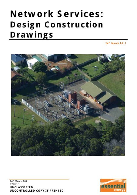
<strong>Network</strong> <strong>Services</strong>:<br />
<strong>Design</strong> <strong>Construction</strong><br />
<strong>Drawings</strong><br />
24 th March 2011<br />
24 th March 2011<br />
ISSUE 3<br />
UNCLASSIFIED<br />
UNCONTROLLED COPY IF PRINTED
UNCLASSIFIED<br />
OPERATIONAL MANUAL – <strong>Network</strong> <strong>Services</strong>: <strong>Design</strong> <strong>Construction</strong> <strong>Drawings</strong><br />
CEOM7001<br />
PREPARED BY:<br />
Liaison and Development Officer<br />
AUTHORISED BY:<br />
Group Manager <strong>Network</strong> Asset Systems<br />
DOCUMENT NUMBER: CE OM7001 - ISSUE 3<br />
This plan is copyright. No part may be repr oduced by any proc ess wi thout wri tten permi ssion,<br />
except as permitted under the copyright act.<br />
DISCLAIMER<br />
1 <strong>Essential</strong> E nergy may change the information in this document without notice. Al l changes<br />
take effect on the date made by <strong>Essential</strong> <strong>Energy</strong>. A prin t version is alw ays an uncontrolled<br />
copy. Before using this document, please ensure that it is still current.<br />
2 This document may co ntain confidential information. Restri ctions on the use and di sclosure<br />
of confidential information by employees a re set out in your contract of employment.<br />
Restrictions on the use and disclosure of confidential information by contractors are set out in<br />
your contra ct of enga gement wi th Esse ntial <strong>Energy</strong>. Sub-contractors are bound b y the<br />
confidentiality prov isions set ou t in t heir con tract with the contractor engaged by <strong>Essential</strong><br />
<strong>Energy</strong>.<br />
2011 E SSENTIAL E NERGY<br />
24 March 2011 - Issue 3<br />
Approved By: Group Manager <strong>Network</strong> Asset Systems<br />
Page 2 of 35<br />
UNCLASSIFIED<br />
UNCONTROLLED COPY IF PRINTED
UNCLASSIFIED<br />
OPERATIONAL MANUAL - <strong>Network</strong> <strong>Services</strong>: <strong>Design</strong> <strong>Construction</strong> <strong>Drawings</strong><br />
CEOM7001<br />
CONTENTS PAGE<br />
1 INTRODUCTION .......................................................................................................5<br />
2 WHY THESE INSTRUCTIONS ARE IMPORTANT...............................................................5<br />
3 CHALLENGES ...........................................................................................................5<br />
4 SAFETY AND WORK PRACTICES..................................................................................5<br />
5 THE CONSTRUCTION PLAN DETAILS ...........................................................................5<br />
5.1 Drawing Sheets ........................................................................................................ 6<br />
5.2 Title Block................................................................................................................ 6<br />
5.3 Amendments & Revisions ........................................................................................... 6<br />
5.4 Electronic Level & Layering convention ......................................................................... 7<br />
5.5 Electronic Drawing File Format .................................................................................... 7<br />
5.6 Electronic File Naming Convention ............................................................................... 7<br />
5.7 Accredited Persons .................................................................................................... 7<br />
5.8 Certification ............................................................................................................. 7<br />
5.9 <strong>Design</strong> Alterations..................................................................................................... 7<br />
5.10 Submitting Plans for Certification................................................................................. 8<br />
5.10.1 Hardcopy Plans ........................................................................................................8<br />
5.10.2 Electronic Plans........................................................................................................8<br />
5.11 As Constructed Plans ................................................................................................. 8<br />
5.12 Folding and Filing Hardcopy Plans................................................................................ 8<br />
6 THE CONSTRUCTION PLAN PRESENTATION..................................................................9<br />
6.1 Symbology............................................................................................................... 9<br />
6.2 Line Style and Weight Definitions ................................................................................ 9<br />
6.3 Scaling ...................................................................................................................10<br />
6.4 Scale for Electronic Plans ..........................................................................................10<br />
6.5 Coordinate System for Electronic Plans........................................................................10<br />
6.6 Dimensioning and Annotations ...................................................................................10<br />
6.7 Schedules ...............................................................................................................11<br />
6.8 Schematic Diagrams.................................................................................................11<br />
6.8.1 For High Voltage (HV) Schematics ............................................................................ 11<br />
6.8.2 For Low Voltage (LV) Schematics ............................................................................. 12<br />
6.9 Padmount Substations ..............................................................................................12<br />
6.10 Earthing .................................................................................................................12<br />
6.11 Streetlights .............................................................................................................12<br />
6.12 Interconnection Points ..............................................................................................13<br />
6.13 Asset Labels............................................................................................................13<br />
6.14 Danger Points..........................................................................................................13<br />
6.15 Other <strong>Services</strong>.........................................................................................................13<br />
6.16 Obstructions............................................................................................................13<br />
6.17 Trench Sections .......................................................................................................13<br />
24 March 2011 - Issue 3<br />
Approved By: Group Manager <strong>Network</strong> Asset Systems<br />
Page 3 of 35<br />
UNCLASSIFIED<br />
UNCONTROLLED COPY IF PRINTED
UNCLASSIFIED<br />
OPERATIONAL MANUAL - <strong>Network</strong> <strong>Services</strong>: <strong>Design</strong> <strong>Construction</strong> <strong>Drawings</strong><br />
CEOM7001<br />
6.18 Easements ..............................................................................................................13<br />
6.19 Reimbursement scheme............................................................................................13<br />
6.20 Safety or Environmental Hazards ...............................................................................13<br />
7 DETAIL OVERVIEW REQUIRED FOR CONSTRUCTION PLANS.......................................... 14<br />
7.1 General Details ........................................................................................................14<br />
7.2 Cadastre Details ......................................................................................................14<br />
7.3 Electrical Installation Details ......................................................................................15<br />
8 REFERENCES ......................................................................................................... 35<br />
9 REVISIONS............................................................................................................ 35<br />
24 March 2011 - Issue 3<br />
Approved By: Group Manager <strong>Network</strong> Asset Systems<br />
Page 4 of 35<br />
UNCLASSIFIED<br />
UNCONTROLLED COPY IF PRINTED
UNCLASSIFIED<br />
OPERATIONAL MANUAL - <strong>Network</strong> <strong>Services</strong>: <strong>Design</strong> <strong>Construction</strong> <strong>Drawings</strong><br />
CEOM7001<br />
1 INTRODUCTION<br />
The E ssential E nergy electrica l network is desi gned to delive r a re liable e lectrical energy<br />
supply to c ustomers. A constr uction plan should clearly conv ey t o constru ction staf f al l<br />
information for the co nstruction of or proposed al terations to <strong>Essential</strong> <strong>Energy</strong>’s el ectrical<br />
network. It should also detail changes to a ssociated cad astral such as new allotments or<br />
roadways. The “as c onstructed” pl an wi ll be used to update Es sential <strong>Energy</strong>’s Net work<br />
Asset Management Systems to maintain an a ccurate represen tation of the electr ical<br />
network.<br />
2 WHY THESE INSTRUCTIONS ARE IMPORTANT<br />
This docu ment prov ides det ails of t he st andard constru ction pl an requi rements for the<br />
submission of manua l or e lectronic constr uction plans t o E ssential E nergy. Un iform<br />
practices are i mportant to ensure that the i nformation is accu rate an d consist ent t o allow<br />
the work to be constructed and data processed without ambiguity.<br />
This docu ment w ill be u nder regu lar rev iew an d f eedback is en couraged f rom an yone<br />
reading this document. For further information or for any queries relating to this document,<br />
contact <strong>Network</strong> Asset Systems Section at <strong>Essential</strong> <strong>Energy</strong>.<br />
3 CHALLENGES<br />
The construction plans must be co nsistent in th e presentation of design information, notes,<br />
diagrams, sch ematics an d sch edules w hich w ill a llow f or a cl ear in terpretation of the<br />
information con cerning an y addit ion or alt eration t o Essen tial E nergy’s elect rical n etwork<br />
assets.<br />
A comprehensive construction plan standard will lead to:<br />
• A clear understanding of what is required by designer<br />
• A clear and complete understanding of what is required by construction staff<br />
• A clear interpretation of plans and schedules by <strong>Essential</strong> <strong>Energy</strong>’s delegated staff<br />
• Standardised electronic construction plans for viewing, printing and reference.<br />
4 SAFETY AND WORK PRACTICES<br />
<strong>Design</strong>s must allow for and adhere to the standard safety work practices routinely employed<br />
in the construction and maintenance activities within <strong>Essential</strong> <strong>Energy</strong>.<br />
All designs must adhe re to <strong>Essential</strong> <strong>Energy</strong> ’s Subtrans mission an d Distribution <strong>Network</strong><br />
Planning Criteria and Guidelines (CEPG8003).<br />
5 THE CONSTRUCTION PLAN DETAILS<br />
<strong>Construction</strong> pl ans are i ntended to provi de direction for constr uction staff as well as<br />
facilitate the updati ng of Essen tial <strong>Energy</strong>’s corporate Asset Manage ment systems. Colour<br />
electronic construction plans should be able to be printed in black and white without loss of<br />
clarity.<br />
24 March 2011 - Issue 3<br />
Approved By: Group Manager <strong>Network</strong> Asset Systems<br />
Page 5 of 35<br />
UNCLASSIFIED<br />
UNCONTROLLED COPY IF PRINTED
UNCLASSIFIED<br />
OPERATIONAL MANUAL - <strong>Network</strong> <strong>Services</strong>: <strong>Design</strong> <strong>Construction</strong> <strong>Drawings</strong><br />
CEOM7001<br />
5.1 Drawing Sheets<br />
Hardcopy plans s hould show the sheet size used in the title bl ock or other suitable locat ion<br />
and shall be drawn on one of the following sheet sizes:<br />
• A0 Landscape or Portrait orientation<br />
• A1 Landscape or Portrait orientation<br />
• A2 Landscape or Portrait orientation<br />
• A3 Landscape or Portrait orientation<br />
• A4 Landscape orientation<br />
Hardcopy plans that have been enlarged or reduced from the original size shall be<br />
annotated as “Not to Scale” in Title Block or at a suitable location on the plan.<br />
5.2 Title Block<br />
The t itle block sh ould prov ide in formation relev ant f or t he iden tification of the work,<br />
location, construction, data collection and filing. The title block should appear at the bottom<br />
right hand corner of the sheet where possible. The following details shall appear in the title<br />
block:<br />
• Should be a combination of or some of the<br />
Description<br />
following: Address, Name of Customer, Subdivision<br />
or Development Name & Stage (if applicable).<br />
Drawing Number • Project No. (Supplied by EE)<br />
Scale<br />
• The scale of the printed drawing. (Should be “Not To<br />
Scale” if drawing is printed at reduced scale)<br />
Drawn By • Name of <strong>Design</strong>er.<br />
Project Cost Number • Project No. (Supplied by EE)<br />
Issue • The current drawing revision issue (initial revision A)<br />
Date Issued • Date drawing finalised by designer.<br />
Amendment Details<br />
• Shall record any alterations made to final plan after<br />
date of original issue.<br />
The owner of the construction plan document (i.e. Company or Contractor Name/Logo) shall<br />
also be located in or near the title block. Other relevant information to the design may also<br />
be placed in the title block.<br />
Please refer to Attachment K for example of <strong>Essential</strong> <strong>Energy</strong>’s Standard Title Block layout<br />
and amendment notation.<br />
5.3 Amendments & Revisions<br />
The original issue shall be deemed Issue A. Subsequent issues of the drawing shall be called<br />
Issue B, then Issue C etc. Ame ndments details shall be sho wn in the title bloc k and have<br />
the following:<br />
• Issue Followed by the amendment details<br />
• By Name of person making alterations<br />
• Date Date of alterations<br />
Please refer to Attachment K for example of <strong>Essential</strong> <strong>Energy</strong>’s Standard Title Block layout<br />
and issue notation.<br />
24 March 2011 - Issue 3<br />
Approved By: Group Manager <strong>Network</strong> Asset Systems<br />
Page 6 of 35<br />
UNCLASSIFIED<br />
UNCONTROLLED COPY IF PRINTED
UNCLASSIFIED<br />
OPERATIONAL MANUAL - <strong>Network</strong> <strong>Services</strong>: <strong>Design</strong> <strong>Construction</strong> <strong>Drawings</strong><br />
CEOM7001<br />
5.4 Electronic Level & Layering convention<br />
Please refer to Attach ment J for a breakdow n of the <strong>Essential</strong> E nergy C omputer Aided<br />
Drafting (i.e. CAD) levels or layering standard.<br />
5.5 Electronic Drawing File Format<br />
All electronic plans shall be free of viruses and can be supplied any of the following formats:<br />
• Microstation drawing file (DGN or RDL)<br />
• AutoCAD drawing file (DWG)<br />
• Drawing Exchange Format (DXF) release 12 or later<br />
• Adobe PDF (Provided a plan in one of the above formats is also submitted).<br />
5.6 Electronic File Naming Convention<br />
When naming an electronic version of the cons truction plan the filename given should allow<br />
the fi le to be i dentified as part o f a project. Th e f ilename sh ould also clearly state what<br />
revision it is.<br />
The fi lename gi ven to the el ectronic constru ction plan file should adhere to the following<br />
guidelines:<br />
• Should contai n a p roject num ber, certi fication or other num ber that allows<br />
identification of the project to which the construction plan belongs<br />
• Should contain a file or sheet reference if there is more then one file (i.e. 1 of 2)<br />
• Should contain the revision or amendment issue<br />
• A file extension (eg. DGN, RDL, DWG, DXF)<br />
• The filename should not contain a full stop (i.e. a “.” character) other then to separate<br />
the file name from the extension<br />
• It should also not contain any of the following characters:<br />
5.7 Accredited Persons<br />
( ) ? ! @ # $ % ^ * “ ” ~ ` , ; : { } [ ]<br />
All plans submitted to <strong>Essential</strong> <strong>Energy</strong> fo r certification must carry the <strong>Design</strong>er’s<br />
Accreditation Number. Plans submitted from no n-accredited persons or not bearing a valid<br />
accreditation number will be rejected.<br />
5.8 Certification<br />
All constructi on pl ans must be approved by Esse ntial <strong>Energy</strong> 's Planning M anager or<br />
delegated person. Evidence of approval by all other service providers (Telstra, W ater, Gas,<br />
etc.) that may be affected sha ll be supplied with the plan. T he evidence supplied shall be<br />
up to date at time of submission.<br />
5.9 <strong>Design</strong> Alterations<br />
Any devi ation from th e submi tted pl ans du ring the c onstruction phase mu st fi rst be<br />
approved in writing by <strong>Essential</strong> <strong>Energy</strong>'s delegated person. A ll deviations from the original<br />
plan are to be included on an “As Constructed” plan that should be s ubmitted when works<br />
are completed.<br />
24 March 2011 - Issue 3<br />
Approved By: Group Manager <strong>Network</strong> Asset Systems<br />
Page 7 of 35<br />
UNCLASSIFIED<br />
UNCONTROLLED COPY IF PRINTED
UNCLASSIFIED<br />
OPERATIONAL MANUAL - <strong>Network</strong> <strong>Services</strong>: <strong>Design</strong> <strong>Construction</strong> <strong>Drawings</strong><br />
CEOM7001<br />
5.10 Submitting Plans for Certification<br />
All construction plans (hardcopy and electronic) should be submitted to <strong>Essential</strong> <strong>Energy</strong> for<br />
certification. The certified construction plan will be returned to designer.<br />
5.10.1 Hardcopy Plans<br />
Every construction drawing shall display the following certification stamp:<br />
5.10.2 Electronic Plans<br />
<strong>Essential</strong> <strong>Energy</strong> can ac cept construction plans submitted in Adobe Ac robat format (PDF) e-<br />
mailed to the Pl anning Protecti on Con nection Of ficer together wi th pl ans s upplied as per<br />
Section 5.5. A certified Adobe Acrobat plan will be returned via return e-mail.<br />
When plans are su pplied in a f ormat as per Sect ion 5.5, then <strong>Essential</strong> <strong>Energy</strong> may create<br />
an Adobe Acrobat (PDF) file and certify it by means of a digital signature, before returning it<br />
via return e-mail.<br />
5.11 As Constructed Plans<br />
Upon comp letion of the constr uction an “ As Constructed” Pl an should be returned to<br />
<strong>Essential</strong> E nergy in an accept able elect ronic f ormat an d clearly ma rked “ As Con structed”.<br />
Plan sh ould sh ow all asset s correct ly labe lled an d any dev iations f rom t he orig inal a s<br />
designed construction plan.<br />
5.12 Folding and Filing Hardcopy Plans<br />
All hard copy cons truction plans should be fold ed into A4 si ze with the title block vi sible in<br />
the bottom ri ght hand corner. All attachments to these plans should be stapl ed to the top<br />
left hand corner of the plan.<br />
24 March 2011 - Issue 3<br />
Approved By: Group Manager <strong>Network</strong> Asset Systems<br />
Page 8 of 35<br />
UNCLASSIFIED<br />
UNCONTROLLED COPY IF PRINTED
UNCLASSIFIED<br />
OPERATIONAL MANUAL - <strong>Network</strong> <strong>Services</strong>: <strong>Design</strong> <strong>Construction</strong> <strong>Drawings</strong><br />
CEOM7001<br />
6 THE CONSTRUCTION PLAN PRESENTATION<br />
6.1 Symbology<br />
All symbol s rel ating to the produ ction of co nstruction plans must conform to <strong>Essential</strong><br />
<strong>Energy</strong>’s standard symbology (refer to Attachments F, G & H). All symbols should be scaled<br />
correctly and consistently in line with the overall scale used for the construction plan.<br />
6.2 Line Style and Weight Definitions<br />
Line styl es or li ne types are used to represent di fferent conductor or cabl e types on the<br />
construction pl an. <strong>Essential</strong> En ergy has d eveloped a num ber of line styles for use o n<br />
construction plans. The following table shows examples of line styles in use by EE.<br />
Style<br />
Name<br />
Description<br />
Representation<br />
Table 7.1 Microstation Line Styles<br />
Line styles and line weight (line thickness) are used to represent different cable types. The<br />
line weight is a term used to describe the thickness of a line and is sometimes known as Pen<br />
Thickness. T he following table describes the relationship of line weight to pen thicknesses<br />
used in <strong>Essential</strong> <strong>Energy</strong>’s standard construction drawings.<br />
Line Weight<br />
0 0.25<br />
1 0.35<br />
2 0.5<br />
3 0.7<br />
4 1.0<br />
5 1.2<br />
Line (Pen) Width (mm)<br />
Table 7.2 Line Weights to Pen Thickness<br />
For a compreh ensive li st of all E ssential E nergy’s lin e st yles an d weigh ts, please ref er t o<br />
Attachment I.<br />
24 March 2011 - Issue 3<br />
Approved By: Group Manager <strong>Network</strong> Asset Systems<br />
Page 9 of 35<br />
UNCLASSIFIED<br />
UNCONTROLLED COPY IF PRINTED
UNCLASSIFIED<br />
OPERATIONAL MANUAL - <strong>Network</strong> <strong>Services</strong>: <strong>Design</strong> <strong>Construction</strong> <strong>Drawings</strong><br />
CEOM7001<br />
6.3 Scaling<br />
Hardcopy plans shall be drawn to an approp riate scale to show a ll design in formation<br />
legibly. A ll scales u sed on t he draw ing sh ould be in dicated in t he t itle bl ock o r n ear t he<br />
appropriate drawing detail. The following scales are to be used:<br />
<strong>Construction</strong> Plan<br />
1:500<br />
1:1000<br />
1:1250<br />
1:1500<br />
1:2000<br />
1:2500<br />
1:4000<br />
1:5000<br />
*1:7000 & above<br />
Note: * Should only to be used in sparsely populated areas.<br />
Details on plans<br />
1:100<br />
1:200<br />
1:250<br />
1:400<br />
6.4 Scale for Electronic Plans<br />
Schematic Diagrams<br />
As required (URD LV)<br />
As required (URD HV)<br />
Not To Scale<br />
(Rural HV/LV)<br />
The plan s hall be drawn at true scale (i.e. 1 unit: 1 metre). Hardcopy pri nts s hould be<br />
produced at appropriate scales (refer to 6.3). All symbols and annotation should be inserted<br />
scaled correct scale factor.<br />
6.5 Coordinate System for Electronic Plans<br />
Where t he construction plan is spat ially loc ated u sing a mappin g coordin ate sy stem, it is<br />
preferred that the coordinate system used be MGA94 zone 54, 55 or 56.<br />
6.6 Dimensioning and Annotations<br />
All di mensioning and annotati ons shal l be arra nged so that they can be read from the<br />
bottom or right hand side of the dr awing sheet. All text should be legible and be displayed<br />
at least 1.8mm in height for the appropriate scale of the construction plan or when printed<br />
to hardcopy.<br />
Text sho wn on plans should be in a t ext st yle ( i.e. f ont) t hat is easy t o read. E ssential<br />
<strong>Energy</strong> has a preference for standard font styles such as ISO or Arial.<br />
All d imensions sh all be in met ric. L inear di mensions sh ould be show n in metres ( m) and<br />
angular dimensions shown in degrees and mi nutes. Al l notes, text and dimensions<br />
(excluding Asset Labe ls) should be placed on a l evel or l ayer dedi cated to text or<br />
dimensions.<br />
24 March 2011 - Issue 3<br />
Approved By: Group Manager <strong>Network</strong> Asset Systems<br />
Page 10 of 35<br />
UNCLASSIFIED<br />
UNCONTROLLED COPY IF PRINTED
UNCLASSIFIED<br />
OPERATIONAL MANUAL - <strong>Network</strong> <strong>Services</strong>: <strong>Design</strong> <strong>Construction</strong> <strong>Drawings</strong><br />
CEOM7001<br />
Dimensions should adhere to the following:<br />
• For overhead spans the span lengths sho uld be shown to the neares t 0.1 metre (m)<br />
and placed at or near the midpoint of span. Dimension lines are not required<br />
• It is acceptable for angles to be shown to the nearest degrees (i.e. 36 o 43’ -> 37 o )<br />
• All underground cable lengths should be shown in the underground cable schedule<br />
• Other dimensions required for construction may use dimension lines as required.<br />
6.7 Schedules<br />
Schedules provide a structured layout of information relevant to the job. The main purpose<br />
of the schedule is to reduce t he amount of detail and congestion shown on the construction<br />
plan w hich sh ould mak e it eas ier t o read. Schedules are n ot in tended t o be u sed f or<br />
estimating or used as a comprehensive material list.<br />
Schedules, where possible, should appear on the same sheet as the design. If this is not<br />
possible then schedules should be placed onto a sep arate sheet. T his she et should b e<br />
allocated the same drawi ng number as construc tion plan and given the next she et number<br />
(e.g. <strong>Construction</strong> Plan: Sheet No.1 and Schedules: Sheet No.2).<br />
A separate schedule is required for (Refer to Attachments for examples):<br />
• Overhead <strong>Construction</strong><br />
• Overhead Conductor<br />
• Streetlight<br />
• Underground <strong>Construction</strong><br />
• Underground Cable and Conduit.<br />
6.8 Schematic Diagrams<br />
Schematic diagrams are required for operatio nal purposes. HV schematic diagrams are<br />
required to be shown on all construction plans and should identify how new works fit in with<br />
existing network.<br />
6.8.1 For High Voltage (HV) Schematics<br />
If any alterations or additions to the high voltage (HV) network are involved, a High Voltage<br />
Schematic Diagram shall be provided. As a minimum the HV sche matic should show up to<br />
the first approved switching poin t and substation (Whether they appear on the construction<br />
plan or not) and should include the following:<br />
• Substation Sites (with Asset Label)<br />
• Switches (with Asset Label & Normal Operating State i.e. open or closed)<br />
• High voltage pits (with Asset Label)<br />
• High voltage cubicles (with Asset Label)<br />
• Open points<br />
• Live Line Clamps<br />
• Future connections<br />
24 March 2011 - Issue 3<br />
Approved By: Group Manager <strong>Network</strong> Asset Systems<br />
Page 11 of 35<br />
UNCLASSIFIED<br />
UNCONTROLLED COPY IF PRINTED
UNCLASSIFIED<br />
OPERATIONAL MANUAL - <strong>Network</strong> <strong>Services</strong>: <strong>Design</strong> <strong>Construction</strong> <strong>Drawings</strong><br />
CEOM7001<br />
Both existing and proposed netwo rk shall be shown and annotated to indicate “existing” or<br />
“proposed” (eg “Existing Sub 33-1 2345”). Depending on the complexity of the project, HV<br />
schematic should be shown even though changes are only on the LV system. Symbols shall<br />
be consistent wi th Es sential <strong>Energy</strong>’s EN MAC system as shown in ATTA CHMENT F –<br />
ELECTRICAL SYMBOL OGY: SCH EMATICS a nd ATTA CHMENT G - TYPI CAL SCHE MATIC<br />
DIAGRAMS.<br />
6.8.2 For Low Voltage (LV) Schematics<br />
Low Vol tage (LV) sc hematics are generally not required unl ess t he LV i nterconnects wi th<br />
existing L V n etwork. L V Sch ematics are n ot requ ired f or isol ated ru ral n etworks or<br />
substations that do not have LV associated with t hem that co uld connect into adjacent<br />
existing LV. Where streetlight circuits are su pplied separatel y from the LV ci rcuit, then a<br />
separate streetlight schematic should be shown.<br />
The LV sc hematic should show up to the ne w or existing substa tions and include the<br />
following:<br />
• Substation sites (with Asset Label)<br />
• Switches (Asset Label & Normal Operating State i.e. open or closed)<br />
• Low voltage cubicles containing switches (with Asset Label)<br />
• MEN points<br />
• Open points<br />
• Future connections<br />
• LV service connection details at both sides of new LV Open points.<br />
Both existing and proposed netwo rk shall be shown and annotated to indicate “existing” or<br />
“proposed” (e.g. “Proposed LVL12345”). Refer to ATTACHMENT F – ELECTRICAL<br />
SYMBOLOGY: SCHEMATICS and ATTACHMENT G - TYPICAL SCHEMATIC DIAGRAMS.<br />
6.9 Padmount Substations<br />
The physica l orientation of padmount s ubstations shall b e shown (e .g. “HV EN D TO FACE<br />
ROADWAY”).<br />
6.10 Earthing<br />
Where a co unterpoise earthing system is use d, the location and detail s should be noted i n<br />
the construction schedule.<br />
Where a co unterpoise earthing system is not used, the location of the earth wire shall b e<br />
recorded on the plan and construction schedule. The type of substation earthing to be used<br />
shall also be shown (e.g. combined or separate HV & LV earthing system).<br />
6.11 Streetlights<br />
<strong>Construction</strong> plans should show all details associated with the installation of or alterations to<br />
any <strong>Essential</strong> <strong>Energy</strong> Streetlights affected by construction work and include a streetlight<br />
schedule (see Attachment E).<br />
<strong>Design</strong>ers should apply the correct Tariff Type to each streetlight installation (Refer to<br />
CEOP1023 Public Lighting: Management Plan). The designer must ensure the Tariff Type is<br />
noted in the schedule on the construction plan.<br />
24 March 2011 - Issue 3<br />
Approved By: Group Manager <strong>Network</strong> Asset Systems<br />
Page 12 of 35<br />
UNCLASSIFIED<br />
UNCONTROLLED COPY IF PRINTED
UNCLASSIFIED<br />
OPERATIONAL MANUAL - <strong>Network</strong> <strong>Services</strong>: <strong>Design</strong> <strong>Construction</strong> <strong>Drawings</strong><br />
CEOM7001<br />
6.12 Interconnection Points<br />
All proposed connections of the new system into the existing underground and/or overhead<br />
system shall be shown.<br />
6.13 Asset Labels<br />
All new and existing <strong>Essential</strong> <strong>Energy</strong> assets s hown on th e construction plans should have<br />
an asset label clearly indicated. It is acceptable to annotate all new <strong>Essential</strong> <strong>Energy</strong> assets<br />
appearing on the construction plan w ith th e ph ysical la bel t hat is issued t o th e f ield ( eg<br />
SUB22345). If known the FSC Ar ea Code may be inclu ded as a pr efix to substation and<br />
switch labels.<br />
All Asset Labels will be provided to the constructing ASP when they present with a Notice to<br />
Commence Constr uction. Asset Labels di stributed for i nternal construc tion wi ll be in<br />
accordance with CEOP8042 <strong>Network</strong>s: Asset Identification & Operational Labels.<br />
6.14 Danger Points<br />
All points of potential d anger where works need to be carried out near mains which are or<br />
may become energised shall be clearly indicated on the plan.<br />
6.15 Other <strong>Services</strong><br />
Other services crossing Es sential <strong>Energy</strong> co nductors or cables sha ll be record ed and the<br />
type of service indicated (e.g. Telstra, water, stormwater or sewerage).<br />
6.16 Obstructions<br />
All known obstructions to the works are to be indicated on the plan.<br />
6.17 Trench Sections<br />
Cable trench sections not complying with the <strong>Essential</strong> <strong>Energy</strong> standard shall have its depth,<br />
width and cable configuration clearly shown on plans.<br />
6.18 Easements<br />
Where known, reference to existing and pro posed easements s hould be indicated on plans<br />
together with registration details.<br />
6.19 Reimbursement scheme<br />
Details of ex isting Reimbu rsement Sch emes w ill be su<br />
Reimbursement Staff on request at time of design.<br />
pplied by <strong>Essential</strong> E nergy<br />
Details of any ne w Rei mbursement Schem e to cover a propose d construction will be<br />
completed by <strong>Essential</strong> <strong>Energy</strong> Reimbursement st aff when project is ready to proceed or at<br />
time of connection.<br />
6.20 Safety or Environmental Hazards<br />
Safety and Environment hazards and their associated controls should be clearly shown and<br />
noted on construction plans in accordance with CECM1000.90 – SSHE Manual Handbook.<br />
24 March 2011 - Issue 3<br />
Approved By: Group Manager <strong>Network</strong> Asset Systems<br />
Page 13 of 35<br />
UNCLASSIFIED<br />
UNCONTROLLED COPY IF PRINTED
UNCLASSIFIED<br />
OPERATIONAL MANUAL - <strong>Network</strong> <strong>Services</strong>: <strong>Design</strong> <strong>Construction</strong> <strong>Drawings</strong><br />
CEOM7001<br />
7 DETAIL OVERVIEW REQUIRED FOR CONSTRUCTION PLANS<br />
Information required for construction plans and schedules are as follows:<br />
7.1 General Details<br />
<br />
<br />
<br />
<br />
<br />
<br />
<br />
<br />
<br />
<br />
<br />
<br />
<br />
<br />
North Indicator (indicating grid North or Magnetic North)<br />
<strong>Design</strong>er’s accreditation number<br />
Relevant drawing references<br />
All symbology to <strong>Essential</strong> <strong>Energy</strong> Standards<br />
Title block completed<br />
Plan Amendments - noted & dated. Revision issue updated (eg A, B etc)<br />
Legends<br />
Safety and Environmental hazards and associated controls indicated<br />
Notes: All Safety and Environment Hazards notes clearly shown<br />
Notes: Any special conditions from local council or RTA noted on plan<br />
Notes: Indicating who is responsible for trenching, clearing, service work etc.<br />
Notes: Disclaimers shown as required<br />
Notes: Environmental conditions<br />
Notes: Cable destination label requirement note added<br />
Overhead and/or Underground <strong>Construction</strong> Schedules (Attachment A and/or C)<br />
<br />
Overhead Conductor and/or Underground Cable & Conduit Schedules (Attachment B<br />
and/or D)<br />
Streetlight Schedule (Attachment E)<br />
<br />
Stringing charts (Only required if outside <strong>Essential</strong> <strong>Energy</strong> <strong>Design</strong> Standards)<br />
7.2 Cadastre Details<br />
<br />
<br />
<br />
<br />
<br />
<br />
<br />
<br />
<br />
<br />
<br />
Streets and Roads (Including Names)<br />
Access tracks, fences, gates shown<br />
New allotment boundaries and numbers (including parks & reserves)<br />
New allotment dwelling densities<br />
Existing allotment number of subdivision<br />
Existing allotments and numbers adjacent to new work (i.e. deposited plan number,<br />
section number and lot number)<br />
Easement details (proposed and existing) including registration details.<br />
Reimbursement Scheme and Number<br />
Environmentally sensitive areas<br />
Distance and indicator to nearest road intersection & other information to clearly<br />
identify location of site<br />
Any Special Features shown (eg rock holes)<br />
24 March 2011 - Issue 3<br />
Approved By: Group Manager <strong>Network</strong> Asset Systems<br />
Page 14 of 35<br />
UNCLASSIFIED<br />
UNCONTROLLED COPY IF PRINTED
UNCLASSIFIED<br />
OPERATIONAL MANUAL - <strong>Network</strong> <strong>Services</strong>: <strong>Design</strong> <strong>Construction</strong> <strong>Drawings</strong><br />
CEOM7001<br />
7.3 Electrical Installation Details<br />
<br />
<br />
<br />
<br />
<br />
<br />
Substation Sites with <strong>Essential</strong> <strong>Energy</strong> Asset Labels & rating (new and existing)<br />
Switches with <strong>Essential</strong> <strong>Energy</strong> Asset Labels (new and existing)<br />
Poles with <strong>Essential</strong> <strong>Energy</strong> Asset Labels (new and existing)<br />
Stays<br />
Streetlights with <strong>Essential</strong> <strong>Energy</strong> Asset Labels (new and existing)<br />
Conductors (single line representation)<br />
Overhead conductors span lengths (Refer to Section 6.6)<br />
<br />
<br />
<br />
<br />
<br />
Overhead conductor deviation angles i.e. take-off angles and in line angles (Refer to<br />
Section 6.6)<br />
Overhead conductor fittings e.g. vibration dampers, bird diverters, aircraft marker and<br />
LV spreaders<br />
Cables (show individual cables)<br />
Cable joints<br />
Cable markers shown in rural areas. (Refer to CEOM7201.15 Electricity Cable Danger<br />
Sign)<br />
Trenches: Identify shared trenches (Refer to Section 6.17)<br />
<br />
<br />
<br />
<br />
<br />
<br />
<br />
<br />
<br />
<br />
<br />
Existing cable/conductor sizes shown<br />
Cubicles with <strong>Essential</strong> <strong>Energy</strong> Asset Labels (new and existing)<br />
Service pits<br />
Conduits (including spare)<br />
Point of Supply (not required for subdivisions)<br />
<strong>Services</strong> with phasing<br />
Load densities shown (e.g. No of units, pump ratings etc)<br />
Vibration dampers (plan and construction schedule)<br />
Air navigation markers for circuit over crossings (plan and construction schedule)<br />
Aircraft and/or bird warning markers (plan and construction schedule)<br />
LV spreaders (plan and construction schedule)<br />
Earths (Refer to Section 6.10)<br />
<br />
<br />
<br />
<br />
Private poles identified<br />
Obstructions and other services (eg water mains, communication lines etc.)<br />
Existing mains at points of connection through to nearest substation and switching<br />
point where possible<br />
Existing residences, sheds, pumping stations etc. to be supplied from new mains.<br />
Ratings of loads of 50kVA or greater that are to be connected (e.g. pumping stations)<br />
must be indicated<br />
HV Schematic (Identify proposed & existing – Refer to Section 6.8.1)<br />
<br />
LV Schematic (only where LV is interconnected. Identify proposed & existing – Refer<br />
to Section 6.8.2)<br />
24 March 2011 - Issue 3<br />
Approved By: Group Manager <strong>Network</strong> Asset Systems<br />
Page 15 of 35<br />
UNCLASSIFIED<br />
UNCONTROLLED COPY IF PRINTED
UNCLASSIFIED<br />
OPERATIONAL MANUAL – <strong>Network</strong> <strong>Services</strong>: <strong>Design</strong> <strong>Construction</strong> <strong>Drawings</strong><br />
CEOM7001<br />
ATTACHMENT A - OVERHEAD CONSTRUCTION SCHEDULE<br />
This schedule must contain all information relevant to the design, construction and recording of the structures associated with overhead work on the<br />
construction plan. All constructions include additions and erection of new assets, the modification and recovery of existing assets.<br />
The following information must be provided for every pole site affected by the construction:<br />
• Asset Label - Mandatory for all new and existing poles (where available).<br />
• Peg No - Number used to identify location on plan. This can be used to indicate existing assets where labels are<br />
not able to be (or yet to be) determined.<br />
• Standard Drawing No. - A standard drawing no. reference for each construction type at each pole site.<br />
• Assembly No. - Assembly No if indicated on <strong>Essential</strong> <strong>Energy</strong> Standard <strong>Drawings</strong>. Otherwise left blank.<br />
• <strong>Construction</strong> Notes:<br />
• Switches - Switch type, phases, voltage & Asset Label<br />
• Substations - Include kVA, phases, voltage & Asset Label<br />
• <strong>Construction</strong>s Type - Include all x-arms, stays, anchors, footings, sink depth, vibration dampers, etc.<br />
• <strong>Construction</strong> Status - Used to indicate status for constructions: Install, Add, Existing, Relocate or Recover<br />
• Earthing - Indicate MEN and earthing details<br />
• Other - Note all other relevant details for each pole site.<br />
OVERHEAD CONSTRUCTION SCHEDULE Example<br />
Peg No.<br />
Asset Standard Drawing Assembly<br />
Label<br />
No.<br />
No.<br />
<strong>Construction</strong> Notes<br />
9 CE12345 7101.03 ERECT 14m 8kN POLE - SINK 2.15m DEEP<br />
7101.20 2 INSTALL 11kV 3 PHASE TERMINATION - 2.4m TYPE S5 X'ARM<br />
7106.01 INSTALL VIBRATION DAMPERS - 1 PER CONDUCTOR<br />
Please Note: The schedules contained in these attachments are examples only and have been included to illustrate layout only.<br />
24 March 2011 - Issue 3<br />
Approved By: Group Manager <strong>Network</strong> Asset Systems<br />
Page 16 of 35<br />
COMMERCIAL-IN-CONFIDENCE UNCONTROLLED COPY IF PRINTED
UNCLASSIFIED<br />
OPERATIONAL MANUAL - <strong>Network</strong> <strong>Services</strong>: <strong>Design</strong> <strong>Construction</strong> <strong>Drawings</strong><br />
CEOM7001<br />
ATTACHMENT B - OVERHEAD CONDUCTOR SCHEDULE<br />
This schedule must contain all information relevant to the design , construction and recording associated with overhead conductor work on<br />
the construction plan. Details should include erection of new and the recovery of existing conductor.<br />
The following information must be provided for all conductors affected by the construction:<br />
• Route of stringing - ‘From’ and ‘To’ pole (asset label) or peg sites.<br />
• Voltage - Nominal voltage that conductor will be energized at. (eg LV, 11kV …)<br />
• Conductor Types - Conductor Name/Code<br />
• <strong>Construction</strong> Status - Indicate for all constructions: Install, Add, Existing, Relocate or Recover<br />
• <strong>Design</strong> Tension - % UTS @ <strong>Design</strong> Temperature ( o C).<br />
• Ground Clearance - metres (m) above ground @ max operating temperature ( o C).<br />
• Route length - Route length in metres (m).<br />
• Ruling span - Ruling span in metres (m) used for design calculations.<br />
From<br />
To<br />
Conductor Details Voltage / Wires /<br />
Conductor<br />
OVERHEAD CONDUCTOR SCHEDULE<br />
Route<br />
Length<br />
Example<br />
<strong>Design</strong> Tension<br />
Ruling<br />
Span<br />
Min <strong>Design</strong> GC @ Max<br />
Operating Temp.<br />
25856 25824<br />
RECOVER EXISTING 1 PHASE 11kV<br />
MAINS<br />
25856 25819 ERECT 3 PHASE 7/3.00AAAC 11kV 304m 17<br />
% UTS<br />
@<br />
15<br />
o C 152m 7.3 m @ 65<br />
o C<br />
Please Note: The schedules contained in these attachments are examples only and have been included to illustrate layout<br />
only.<br />
24 March 2011 - Issue 3<br />
Approved By: Group Manager <strong>Network</strong> Asset Systems<br />
Page 17 of 35<br />
UNCLASSIFIED<br />
UNCONTROLLED COPY IF PRINTED
UNCLASSIFIED<br />
OPERATIONAL MANUAL - <strong>Network</strong> <strong>Services</strong>: <strong>Design</strong> <strong>Construction</strong> <strong>Drawings</strong><br />
CEOM7001<br />
ATTACHMENT C - UNDERGROUND CONSTRUCTION SCHEDULE<br />
This schedule must contain all information relevant to the design, construction and recording of the equipment associated with underground<br />
work on th e constructi on pl an. Al l construc tions i nclude addi tions and erecti on of new assets, th e m odification and recovery of existin g<br />
assets.<br />
The following information must be provided for underground sites affected by the construction:<br />
• Asset Label - Mandatory for all new and existing assets<br />
• Standard Drawing No. - A standard drawing no. reference for each construction type at each site.<br />
• Assembly No. - Assembly No if indicated on <strong>Essential</strong> <strong>Energy</strong> Standard <strong>Drawings</strong>. Otherwise left blank.<br />
• <strong>Construction</strong> Notes:<br />
• <strong>Construction</strong> Status - Used to indicate status for constructions: Install, Add, Existing, Relocate or Recover<br />
• Switches - Switchgear type, phases, voltage & Asset Labels<br />
• Substations - Include type (i.e. padmount, indoor or ground), kVA & other relevant details<br />
• <strong>Construction</strong> Types - Include all other equipment types: pits & pillars, terminations (HV/LV & OH to UG)<br />
• Earthing - Indicate MEN & earthing details.<br />
• Cable markers - Shown in rural areas.<br />
• Trenches - Identify shared trenches<br />
• Other relevant details - Signs etc<br />
UNDERGROUND CONSTRUCTION SCHEDULE Example<br />
Asset Label<br />
Standard<br />
Drawing No.<br />
Assembly No.<br />
<strong>Construction</strong> Notes<br />
CE12345 7204.35 ADD 240sqmm AL XLPE PVC / HDPE 11kV UNDERGROUND CABLE TERMINATION<br />
7207.08 ADD 11kV CABLE TERMINATION EARTH<br />
SUB654321 7203.80 INSTALL 750kVA ABB PAD MOUNT SUBSTATION WITH ABB SAFELINK<br />
Please Note: The schedules contained in these attachments are examples only and have been included to illustrate layout<br />
only.<br />
24 March 2011 - Issue 3<br />
Approved By: Group Manager <strong>Network</strong> Asset Systems<br />
Page 18 of 35<br />
UNCLASSIFIED<br />
UNCONTROLLED COPY IF PRINTED
UNCLASSIFIED<br />
OPERATIONAL MANUAL - <strong>Network</strong> <strong>Services</strong>: <strong>Design</strong> <strong>Construction</strong> <strong>Drawings</strong><br />
CEOM7001<br />
ATTACHMENT D - UNDERGROUND CABLE AND CONDUIT SCHEDULE<br />
This schedule must contain all information relevant to the design , construction and recording associated with overhead conductor work on<br />
the construction plan. Details should include erection of new and the recovery of existing conductor.<br />
The following information must be provided for all conductors affected by the construction:<br />
• From & To - Indicate cable route using start and finish Asset Labels. If not an asset use suitable site location no.<br />
• Cable & Conduit Details:<br />
• <strong>Construction</strong> Status - Indicate for all constructions: Install, Add, Recover, Disconnect, Spare etc.<br />
• Voltage - Nominal voltage that conductor will be energized at (eg LV, 11kV)<br />
• Cable Types - Cable Description/Type, Code, Size, No of Cables<br />
• Route length - Route length in metres (m).<br />
UNDERGROUND CABLE & CONDUIT SCHEDULE Example<br />
From To Cable & Conduit Details Route Length<br />
EX. SUB 983862 EX. POLE CE81466 Disconnect Existing 11kV 3 Core 240Sqmm Al XLPE<br />
Cable - Leave Cable In Ground<br />
EX. SUB 983862 EX. PIT 97032340 Disconnect Existing LV 4 Core Solid 240Sqmm Al XLPE<br />
Cable - Leave Cable In Ground<br />
11kV JOINT 'B' SUB 993224 Install 11kV 3 Core 240Sqmm Al XLPE PVC/HDPE Cable 140m<br />
SUB 993224 S/S 97321463 Install 11kV 3 Core 240Sqmm Al XLPE PVC/HDPE Cable 185m<br />
S/S 97321463 NEW POLE CE81466 Install 11kV 3 Core 240Sqmm Al XLPE PVC/HDPE Cable 25m<br />
Please Note: The schedules contained in these attachments are examples only and have been included to illustrate layout<br />
only.<br />
24 March 2011 - Issue 3<br />
Approved By: Group Manager <strong>Network</strong> Asset Systems<br />
Page 19 of 35<br />
UNCLASSIFIED<br />
UNCONTROLLED COPY IF PRINTED
UNCLASSIFIED<br />
OPERATIONAL MANUAL - <strong>Network</strong> <strong>Services</strong>: <strong>Design</strong> <strong>Construction</strong> <strong>Drawings</strong><br />
CEOM7001<br />
ATTACHMENT E - STREETLIGHT CONSTRUCTION SCHEDULE<br />
This sched ule must c ontain al l information relevant to the desi gn, constr uction and rec ording associ ated wi th Streetl ight work on th e<br />
construction plan. Details should include erection of new and the recovery of existing conductor.<br />
A ‘Streetlight Schedule’ shall be shown on all plans where streetlights are being installed. The following information shall be shown:<br />
• Asset Label - Mandatory for all new and existing streetlight poles and columns<br />
• Standard Drawing No. - A standard drawing number reference for each construction type at each site<br />
• Assembly No. - Assembly No if indicated on <strong>Essential</strong> <strong>Energy</strong> Standard <strong>Drawings</strong>. Otherwise left blank<br />
• <strong>Construction</strong> Notes:<br />
• <strong>Construction</strong> Status - Indicate for all constructions: Install, Add, Existing, Erect, Relocate or Recover<br />
• Lantern type - Indicate HPS, MV or Flood Lights, Wattages & PE Cell arrangements<br />
• <strong>Construction</strong> Types - Include all equipment types: columns & heights, anchors & spigots , brackets and all Asset Labels<br />
• Other relevant details - As Required<br />
• Tariff - Include Tariff code (Refer to CEOP1023 – Public Lighting: Management Plan).<br />
STREETLIGHT CONSTRUCTION SCHEDULE Example<br />
Asset Label<br />
Standard Assembly<br />
Drawing No No.<br />
<strong>Construction</strong> Notes<br />
Tariff<br />
CE19772 - CE19773 7206.10 INSTALL STANDARD 7.5m x 3m CURVED SINGLE OUTREACH RATE 2<br />
7206.05 80W MV LANTERN<br />
CE19774 - CE19777 7206.10 INSTALL PRESTIGE 4.5m 'NOSTALGIA' COLUMN ( STYLE 2 ) RATE 2<br />
7206.05 WITH 80W MV LANTERN<br />
Please Note: The schedules contained in these attachments are examples only and have been included to illustrate layout<br />
only.<br />
24 March 2011 - Issue 3<br />
Approved By: Group Manager <strong>Network</strong> Asset Systems<br />
Page 20 of 35<br />
UNCLASSIFIED<br />
UNCONTROLLED COPY IF PRINTED
UNCLASSIFIED<br />
OPERATIONAL MANUAL – <strong>Network</strong> <strong>Services</strong>: <strong>Design</strong> <strong>Construction</strong> <strong>Drawings</strong><br />
CEOM7001<br />
ATTACHMENT F – ELECTRICAL SYMBOLOGY: OVERHEAD AND<br />
UNDERGROUND<br />
Table F1: Symbols for Overhead and Underground<br />
24 March 2011 - Issue 3<br />
Approved By: Group Manager <strong>Network</strong> Asset Systems<br />
Page 21 of 35<br />
UNCLASSIFIED<br />
UNCONTROLLED COPY IF PRINTED
UNCLASSIFIED<br />
OPERATIONAL MANUAL – <strong>Network</strong> <strong>Services</strong>: <strong>Design</strong> <strong>Construction</strong> <strong>Drawings</strong><br />
CEOM7001<br />
ATTACHMENT F – ELECTRICAL SYMBOLOGY: SWITCHES<br />
Table F2: Symbols for Switches<br />
24 March 2011 - Issue 3<br />
Approved By: Group Manager <strong>Network</strong> Asset Systems<br />
Page 22 of 35<br />
UNCLASSIFIED<br />
UNCONTROLLED COPY IF PRINTED
UNCLASSIFIED<br />
OPERATIONAL MANUAL – <strong>Network</strong> <strong>Services</strong>: <strong>Design</strong> <strong>Construction</strong> <strong>Drawings</strong><br />
CEOM7001<br />
ATTACHMENT F – ELECTRICAL SYMBOLOGY: SCHEMATICS<br />
Table F3: Symbols for Schematic Diagrams<br />
24 March 2011 - Issue 3<br />
Approved By: Group Manager <strong>Network</strong> Asset Systems<br />
Page 23 of 35<br />
UNCLASSIFIED<br />
UNCONTROLLED COPY IF PRINTED
UNCLASSIFIED<br />
Operational Manual – <strong>Network</strong> <strong>Services</strong>: <strong>Design</strong> <strong>Construction</strong> <strong>Drawings</strong><br />
CEOM7001<br />
ATTACHMENT G – ELECTRICAL SYMBOLOGY: TYPICAL SCHEMATIC DIAGRAMS<br />
Table G1: Typical Schematic Diagrams<br />
24 March 2011 - Issue 3<br />
Approved By: Group Manager <strong>Network</strong> Asset Systems<br />
Page 24 of 35<br />
UNCLASSIFIED<br />
UNCONTROLLED COPY IF PRINTED
UNCLASSIFIED<br />
OPERATIONAL MANUAL – <strong>Network</strong> <strong>Services</strong>: <strong>Design</strong> <strong>Construction</strong> <strong>Drawings</strong><br />
CEOM7001<br />
ATTACHMENT H – SYMBOLOGY: CADASTRE, TOPOGRAPHIC &<br />
MISCELLANEOUS<br />
Table H1: Symbols for Cadastre, Topographic and other Miscellaneous Uses<br />
24 March 2011 - Issue 3<br />
Approved By: Group Manager <strong>Network</strong> Asset Systems<br />
Page 25 of 35<br />
UNCLASSIFIED<br />
UNCONTROLLED COPY IF PRINTED
UNCLASSIFIED<br />
OPERATIONAL MANUAL – <strong>Network</strong> <strong>Services</strong>: <strong>Design</strong> <strong>Construction</strong> <strong>Drawings</strong><br />
CEOM7001<br />
ATTACHMENT I – LINE STYLES: ELECTRICAL AND OTHER UTILITIES<br />
Table I1: Line Styles for Electricity Cables and Other Utilities<br />
24 March 2011 - Issue 3<br />
Approved By: Group Manager <strong>Network</strong> Asset Systems<br />
Page 26 of 35<br />
UNCLASSIFIED<br />
UNCONTROLLED COPY IF PRINTED
UNCLASSIFIED<br />
OPERATIONAL MANUAL – <strong>Network</strong> <strong>Services</strong>: <strong>Design</strong> <strong>Construction</strong> <strong>Drawings</strong><br />
CEOM7001<br />
ATTACHMENT I – LINE STYLES: CADASTRE AND TOPOGRAPHIC<br />
Table I2: Line Styles for Cadastre and Topographic Features<br />
24 March 2011 - Issue 3<br />
Approved By: Group Manager <strong>Network</strong> Asset Systems<br />
Page 27 of 35<br />
UNCLASSIFIED<br />
UNCONTROLLED COPY IF PRINTED
UNCLASSIFIED<br />
OPERATIONAL MANUAL – <strong>Network</strong> <strong>Services</strong>: <strong>Design</strong> <strong>Construction</strong> <strong>Drawings</strong><br />
CEOM7001<br />
Level 1<br />
Level 2<br />
Level 3<br />
Level 4<br />
Level 5<br />
Level 6<br />
Level 7<br />
Level 8<br />
Level 9<br />
Level 10<br />
Level 11<br />
Level 12<br />
Level 13<br />
Level 14<br />
Level 15<br />
Level 16<br />
Level 17<br />
Level 18<br />
Level 19<br />
Level 20<br />
Level 21<br />
Level 22<br />
Level 23<br />
Level 24<br />
Level 25<br />
Level 26<br />
Level 27<br />
Level 28<br />
Level 29<br />
Level 30<br />
Level 31<br />
Level 32<br />
Level 33<br />
Level 34<br />
Level 35<br />
Level 36<br />
Level 37<br />
Level 38<br />
Level 39<br />
Level 40<br />
Level 41<br />
Level 42<br />
Level 43<br />
Level 44<br />
Level 45<br />
Level 46<br />
Level 47<br />
Level 48<br />
Level 49<br />
Level 50<br />
Level 51<br />
Level 52<br />
Level 53<br />
Level 54<br />
Level 55<br />
Level 56<br />
Level 57<br />
Level 58<br />
Level 59<br />
Level 60<br />
Level 61<br />
Level 62<br />
Level 63<br />
ATTACHMENT J – CAD LEVELS<br />
This table may be beneficial for the purpose of information exchange. <strong>Construction</strong> Plans<br />
produced by <strong>Essential</strong> <strong>Energy</strong> internal design staff and data supplied by <strong>Essential</strong> <strong>Energy</strong><br />
should conform to the following structure.<br />
<strong>Design</strong> Drawing <strong>Construction</strong> Lines<br />
Cable/Conductor EE Owned 19.1kV SWER<br />
Cable/Conductor EE Owned 12.7kV SWER<br />
Cable/Conductor EE Owned LV<br />
Cable/Conductor EE Owned 11kV<br />
Cable/Conductor EE Owned 110kV & 330kV<br />
Cable/Conductor EE Owned 6.35kV SWER<br />
Cable/Conductor EE Owned 6.6kV<br />
Cable/Conductor Owner Not EE<br />
General Text, Dimensions, Annotations & Reference Notes<br />
Poles - EE Owned & Non-Private<br />
Poles Annotation<br />
Poles - Private<br />
Cable/Conductor EE Owned 22kV<br />
Stays - Guys & Catenary<br />
Regulator, Capacitor & Reactor Sites<br />
SWER Isolating & Step Up/Down Substation Sites, Annotation for Regulators & Capacitors<br />
Substations Sites, Annotation for SWER Isolators & Step Up/Down Substation & Reactors<br />
Metering Units, Earth Points, Annotation for Pole and Ground Substation Sites<br />
LV Switches & Annotation for Metering Units<br />
LV Switches Annotation<br />
HV Switches<br />
HV Switches Annotation<br />
Sub Transmission Switches<br />
Sub transmission Switches Annotation<br />
Cable/Conductor EE Owned 33kV<br />
Cable/Conductor EE Owned 66kV<br />
Earth Wires<br />
EE Reimbursement Scheme<br />
Streetlight - EE Owned Cables/Conductor, Luminaries, Nightwatch, Controls & Annotation<br />
EE Service Points<br />
Unallocated<br />
Cable/Conductor EE Owned 132kV<br />
URD Cubicles & Pits<br />
URD Cubicle Annotations<br />
Sites for Recloser, Sectionaliser, Line Fault Indicators<br />
Annotation for Recloser, Sectionaliser, Line Fault Indicators<br />
Unallocated<br />
EE FSC Area Boundaries<br />
Misc Cadastre and Topographic Features<br />
Unallocated<br />
Trees<br />
EE Conduits<br />
EE Environmental Area<br />
EE Text<br />
EE Labels<br />
EE Estate Boundaries<br />
Easements<br />
Easements - EE<br />
EE Maintenance Areas<br />
Railway Features<br />
Water Feature Annotations<br />
Land Parcel Annotation - Lot & DP No<br />
Land Parcels - LIC & EE<br />
Unallocated<br />
Unallocated<br />
Road Feature Annotation<br />
Road and Road Feature<br />
Schematics Symbols, Annotation & Line work<br />
LIC Suburb Boundaries<br />
Water Features<br />
LIC Tile Boundaries<br />
Zone Substations<br />
24 March 2011 - Issue 3<br />
Approved By: Group Manager <strong>Network</strong> Asset Systems<br />
Page 28 of 35<br />
UNCLASSIFIED<br />
UNCONTROLLED COPY IF PRINTED
UNCLASSIFIED<br />
OPERATIONAL MANUAL – <strong>Network</strong> <strong>Services</strong>: <strong>Design</strong> <strong>Construction</strong> <strong>Drawings</strong><br />
CEOM7001<br />
ATTACHMENT K – TITLE BLOCK<br />
Example 1: Title Block<br />
Example 2: Amendment<br />
24 March 2011 - Issue 3<br />
Approved By: Group Manager <strong>Network</strong> Asset Systems<br />
Page 29 of 35<br />
UNCLASSIFIED<br />
UNCONTROLLED COPY IF PRINTED
UNCLASSIFIED<br />
OPERATIONAL MANUAL – <strong>Network</strong> <strong>Services</strong>: <strong>Design</strong> <strong>Construction</strong> <strong>Drawings</strong><br />
CEOM7001<br />
ATTACHMENT L – CONSTRUCTION DRAWING EXAMPLES<br />
The following pages show 4 sample constructi on drawings. Please contact <strong>Essential</strong> <strong>Energy</strong><br />
if you wish to have these supplied in other formats.<br />
(Note: The rest of this page is intentionally blank)<br />
24 March 2011 - Issue 3<br />
Approved By: Group Manager <strong>Network</strong> Asset Systems<br />
Page 30 of 35<br />
UNCLASSIFIED<br />
UNCONTROLLED COPY IF PRINTED
UNCLASSIFIED<br />
OPERATIONAL MANUAL – <strong>Network</strong> <strong>Services</strong>: <strong>Design</strong> <strong>Construction</strong> <strong>Drawings</strong><br />
CEOM7001<br />
ATTACHMENT L – CONSTRUCTION DRAWING EXAMPLES: SMALL RURAL (A3 SIZE)<br />
SAMPLE PLAN 1: SMALL RURAL (A3 SIZE)<br />
24 March 2011 - Issue 3<br />
Approved By: Group Manager <strong>Network</strong> Asset Systems<br />
Page 31 of 35<br />
UNCLASSIFIED<br />
UNCONTROLLED COPY IF PRINTED
UNCLASSIFIED<br />
OPERATIONAL MANUAL – <strong>Network</strong> <strong>Services</strong>: <strong>Design</strong> <strong>Construction</strong> <strong>Drawings</strong><br />
CEOM7001<br />
ATTACHMENT L – CONSTRUCTION DRAWING EXAMPLES: LARGE RURAL (A1 SIZE)<br />
SAMPLE PLAN 2: LARGE RURAL (A1 SIZE)<br />
24 March 2011 - Issue 3<br />
Approved By: Group Manager <strong>Network</strong> Asset Systems<br />
Page 32 of 35<br />
UNCLASSIFIED<br />
UNCONTROLLED COPY IF PRINTED
UNCLASSIFIED<br />
OPERATIONAL MANUAL – <strong>Network</strong> <strong>Services</strong>: <strong>Design</strong> <strong>Construction</strong> <strong>Drawings</strong><br />
CEOM7001<br />
SAMPLE PLAN 3: URD (A1 SIZE)<br />
ATTACHMENT L – CONSTRUCTION DRAWING EXAMPLES: URD (A1 SIZE)<br />
24 March 2011 - Issue 3<br />
Approved By: Group Manager <strong>Network</strong> Asset Systems<br />
Page 33 of 35<br />
UNCLASSIFIED<br />
UNCONTROLLED COPY IF PRINTED
UNCLASSIFIED<br />
OPERATIONAL MANUAL – <strong>Network</strong> <strong>Services</strong>: <strong>Design</strong> <strong>Construction</strong> <strong>Drawings</strong><br />
CEOM7001<br />
ATTACHMENT L – CONSTRUCTION DRAWING EXAMPLES: COMMERCIAL (A1 SIZE)<br />
SAMPLE PLAN 4: COMMERCIAL (A1 SIZE)<br />
24 March 2011 - Issue 3<br />
Approved By: Group Manager <strong>Network</strong> Asset Systems<br />
Page 34 of 35<br />
UNCLASSIFIED<br />
UNCONTROLLED COPY IF PRINTED
UNCLASSIFIED<br />
OPERATIONAL MANUAL – <strong>Network</strong> <strong>Services</strong>: <strong>Design</strong> <strong>Construction</strong> <strong>Drawings</strong><br />
CEOM7001<br />
8 REFERENCES<br />
CECM1000.90 – SSHE Manual Handbook<br />
CEOM7201.15 - Electricity Cable Danger Sign<br />
CEOP1023 – Public Lighting: Management Plan<br />
CEOP8042 – <strong>Network</strong>s: Asset Identification & Operational Labels<br />
CEPG8003 - Subtransmission and Distribution <strong>Network</strong> Planning Criteria and Guidelines<br />
9 REVISIONS<br />
Issue<br />
Number<br />
2<br />
Section<br />
Attachments<br />
1<br />
3<br />
4<br />
5.5<br />
5.6<br />
5.9<br />
6.6<br />
6.7<br />
6.8.2<br />
8<br />
Details of Changes in this Revision<br />
References within document checked & corrected.<br />
Wording revised<br />
Wording revised<br />
Added reference to CEPG8003<br />
Wording Revised and PDF added<br />
File naming convention made more general.<br />
<strong>Design</strong> deviations to b e approved during construction and submitted<br />
on the “as constructed” plan upon completion of works.<br />
Wording about text styles revised.<br />
Revised and reworded<br />
LV Schematic wording revised to exclude Voltage Dro p shown at<br />
extremities.<br />
Added reference to CEPG8003<br />
3 All Sections Update template & references in line with <strong>Essential</strong> <strong>Energy</strong> branding<br />
24 March 2011 - Issue 3<br />
Approved By: Group Manager <strong>Network</strong> Asset Systems<br />
Page 35 of 35<br />
UNCLASSIFIED<br />
UNCONTROLLED COPY IF PRINTED