Portable Garage - Harbor Freight Tools
Portable Garage - Harbor Freight Tools
Portable Garage - Harbor Freight Tools
Create successful ePaper yourself
Turn your PDF publications into a flip-book with our unique Google optimized e-Paper software.
Owner’s Manual & Safety Instructions<br />
Save This Manual Keep this manual for the safety warnings and precautions, assembly, operating,<br />
inspection, maintenance and cleaning procedures. Write the product’s serial number in the back of the manual<br />
near the assembly diagram (or month and year of purchase if product has no number). Keep this manual and<br />
the receipt in a safe and dry place for future reference.<br />
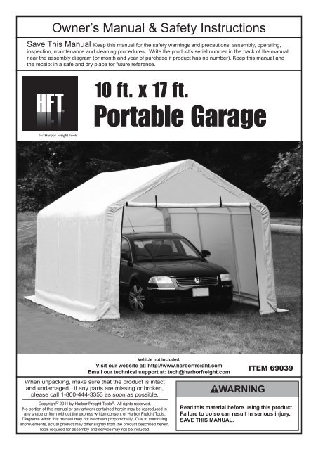
10 ft. x 17 ft.<br />
<strong>Portable</strong> <strong>Garage</strong><br />
Vehicle not included.<br />
Visit our website at: http://www.harborfreight.com<br />
Email our technical support at: tech@harborfreight.com<br />
ITEM 69039<br />
When unpacking, make sure that the product is intact<br />
and undamaged. If any parts are missing or broken,<br />
please call 1-800-444-3353 as soon as possible.<br />
Copyright © 2011 by <strong>Harbor</strong> <strong>Freight</strong> <strong>Tools</strong> ® . All rights reserved.<br />
No portion of this manual or any artwork contained herein may be reproduced in<br />
any shape or form without the express written consent of <strong>Harbor</strong> <strong>Freight</strong> <strong>Tools</strong>.<br />
Diagrams within this manual may not be drawn proportionally. Due to continuing<br />
improvements, actual product may differ slightly from the product described herein.<br />
<strong>Tools</strong> required for assembly and service may not be included.<br />
Read this material before using this product.<br />
Failure to do so can result in serious injury.<br />
SAVE THIS MANUAL.
Table of Contents<br />
Safety.......................................................... 3<br />
Specifications.............................................. 4<br />
Assembly..................................................... 5<br />
Maintenance............................................... 13<br />
Parts List and Diagram............................... 14<br />
Warranty..................................................... 16<br />
SAFETY ASSEMBLY<br />
MAINTENANCE<br />
Double Insulated<br />
WARNING SYMBOLS AND DEFINITIONS<br />
This is the safety alert symbol. It is used to alert you to potential personal injury hazards.<br />
Obey all safety messages that follow this symbol to avoid possible injury or death.<br />
Canadian Standards Association<br />
Underwriters Laboratories, Inc.<br />
Indicates a hazardous situation which, if not avoided,<br />
will result in death or serious injury.<br />
Indicates a hazardous situation which, if not avoided,<br />
could result in death or serious injury.<br />
Indicates a hazardous situation which, if not avoided,<br />
could result in minor or moderate injury.<br />
Addresses practices not related to personal injury.<br />
WARNING marking concerning Risk<br />
of Eye Injury. Wear ANSI‐approved<br />
safety goggles with side shields.<br />
Read the manual before<br />
set-up and/or use.<br />
Page 2 For technical questions, please call 1-800-444-3353. Item 69039
IMPORTANT SAFETY INFORMATION<br />
Read all safety warnings and instructions.<br />
Failure to follow the warnings and instructions may result in serious injury.<br />
Save all warnings and instructions for future reference.<br />
The warnings, precautions, and instructions discussed in this instruction manual cannot cover all possible<br />
conditions and situations that may occur. It must be understood by the operator that common sense<br />
and caution are factors which cannot be built into this product, but must be supplied by the operator.<br />
Assembly Precautions<br />
SAFETY<br />
1. Do not assemble in windy conditions.<br />
2. Assemble and install only on<br />
flat, level, hard surface.<br />
3. Assemble and anchor only according to<br />
these instructions. Improper assembly or<br />
inadequate anchoring can create hazards.<br />
4. Wear ANSI-approved safety goggles and<br />
heavy-duty work gloves during assembly.<br />
5. Keep assembly area clean and well lit.<br />
6. Keep bystanders out of the area during assembly.<br />
7. Do not assemble when tired or when under<br />
the influence of drugs or medication.<br />
8. Product capabilities apply to properly and<br />
completely assembled product only.<br />
Use Precautions<br />
1. Do not use grill or any other type of<br />
fire under cover. Cover may catch fire<br />
if exposed to heat rising from fire.<br />
2. Do not allow snow or debris to<br />
accumulate on this item.<br />
3. Heavy, wet snow or strong wind could cause<br />
damage or sudden collapse. Remove the Cover<br />
when these or similar conditions are expected.<br />
4. This product is not a toy. Do not allow<br />
children to play with or near this item.<br />
5. Use as intended only.<br />
Do not use for long‐term shelter.<br />
6. Inspect regularly, tighten all loose hardware and<br />
loose cords, and secure all loosened anchors.<br />
If any parts are damaged, bent, or stretched, they<br />
must be replaced. Hardware may loosen during<br />
normal operation stresses. Loose hardware<br />
or damaged/altered parts will compromise<br />
the structural integrity of this product.<br />
7. Maintain product labels and nameplates.<br />
These carry important safety information.<br />
If unreadable or missing, contact<br />
<strong>Harbor</strong> <strong>Freight</strong> <strong>Tools</strong> for a replacement.<br />
SAVE THESE INSTRUCTIONS.<br />
MAINTENANCE ASSEMBLY<br />
Item 69039<br />
For technical questions, please call 1-800-444-3353.<br />
Page 3
Specifications<br />
Overall Dimensions 10′ W x 17′ L x 9′ 3″ H<br />
Center Height 9′ 3″<br />
Side Height 6′ 3″<br />
Pole Tubing Diameter 1.27″<br />
SAFETY ASSEMBLY<br />
MAINTENANCE<br />
Page 4 For technical questions, please call 1-800-444-3353. Item 69039
Assembly<br />
Read the ENTIRE IMPORTANT SAFETY INFORMATION section at the beginning of this<br />
manual including all text under subheadings therein before set up or use of this product.<br />
Note: For additional information regarding the parts listed in the following<br />
pages, refer to Parts List and Diagram on page 14.<br />
TO PREVENT SERIOUS INJURY:<br />
Do not leave this product partially assembled. Assemble this product completely at one time.<br />
MAINTENANCE ASSEMBLY<br />
SAFETY<br />
Item 69039<br />
Figure A: Frame Assembly Overview<br />
For technical questions, please call 1-800-444-3353.<br />
Page 5
Roof Frame Assembly<br />
Note: Much of this products assembly is done using slip fit construction. Make sure all parts seat completely<br />
and securely. A rubber mallet (sold separately) can be used to gently tap parts in place to ensure a tight fit.<br />
SAFETY ASSEMBLY<br />
MAINTENANCE<br />
Figure B: Roof Assembly Overview<br />
1. Assemble ridge using three Rails (3) with 4-Way Ridge Connectors (6‐1) between them, and<br />
a 3‐Way Ridge Connector (5-1) on each end.<br />
The Rails connect to the straight ends of the Connectors<br />
and the curved, free ends of the Connectors are angled down, as shown.<br />
Figure C: Ridge Assembly<br />
2. Connect a Rafter (2) to each free end of every Connector (6-1, 5-1), as shown.<br />
Figure D: Rafter Assembly<br />
Page 6 For technical questions, please call 1-800-444-3353. Item 69039
3. Assemble a roof side rail using a 3‐Way Side Connector B (5-3), then three Rails (3) with<br />
4-Way Side Connectors (6‐2) between them, and then a 3‐Way Side Connector A (5-2) on the far end.<br />
The Rails connect to the straight ends of the Connectors,<br />
and the curved ends of all Connectors must face up angled the same direction, as shown.<br />
If that is not the case, incorrect connectors were used, or they were assembled backwards.<br />
6-2<br />
5-3<br />
6-2<br />
3<br />
3<br />
5-2<br />
3<br />
Figure E: Roof Side Rail Assembly<br />
4. Assemble a second identical roof side rail by repeating the instructions in step #3.<br />
SAFETY<br />
5. Connect the roof side rail assemblies to the ends of the Rafters (2), as shown below.<br />
2<br />
5-3<br />
3<br />
6-2<br />
2<br />
6-2<br />
2<br />
5-2<br />
2<br />
6-2<br />
6-2<br />
3<br />
5-3<br />
3<br />
5-2<br />
3<br />
Figure F: Roof Side Rail Installation<br />
6. Make sure all parts assembled up to this point are firmly joined together.<br />
Tap parts together gently with a rubber mallet (sold separately) if needed.<br />
Stud, Foot, and Leg Assembly<br />
1. Assemble a Foot (9) to the bottom of each Center Stud (1-1):<br />
a.<br />
1-1<br />
Place a Foot (9) onto the bottom<br />
of the Center Stud (1‐1).<br />
2. Assemble a Corner Leg (23) to the bottom<br />
of each Corner Stud (1-2) as shown.<br />
9<br />
b.<br />
15<br />
9<br />
1-1<br />
Align the holes and insert a<br />
Pin (15) through them.<br />
16<br />
1-2<br />
c.<br />
15<br />
1-1<br />
16<br />
Insert a Cotter Pin (16) through<br />
the Pin, and spread end open.<br />
9<br />
Figure G: Corner Leg<br />
Assembly<br />
MAINTENANCE ASSEMBLY<br />
23<br />
Item 69039<br />
For technical questions, please call 1-800-444-3353.<br />
Page 7
Stud Installation<br />
1. Have assistants raise one side of the roof assembly.<br />
2. Install the Center Studs (1-1) into the 4-Way Side Connectors (6‐2), and the Corner Studs (1‐2)<br />
into the 3‐Way Side Connector A/B (5-2, 5-3) with the Corner Legs (23) facing inward.<br />
SAFETY ASSEMBLY<br />
MAINTENANCE<br />
Figure H: Stud Installation<br />
3. After all four Studs (1-1, 1-2) are in place, rest that side of the assembly on the ground, and raise the other side.<br />
4. Install four Studs (1-1, 1-2) on the other side of the roof, as explained in step #2, above.<br />
Figure I: Studs Installed on Both Sides<br />
5. Make sure all parts assembled up to this point are firmly joined together.<br />
Tap parts together gently with a rubber mallet (sold separately) if needed.<br />
Page 8 For technical questions, please call 1-800-444-3353. Item 69039
Anchoring Frame<br />
TO PREVENT SERIOUS INJURY: Contact local utility companies to ensure that the installation area is<br />
free of pipes, cables, and other hazards BEFORE installing anchors or choosing installation area.<br />
1. Position the frame in the desired installation location.<br />
The location must be flat, level, and stable with good locations for the Anchors (14‐1).<br />
2. Level the frame end-to-end and side-to-side.<br />
3. Measure the width of the frame at front and back, it should be 10′ 2″ wide.<br />
The distance diagonally in one direction should be equal to the distance diagonally in the other direction.<br />
If any measurements do not match, adjust the frame and retake measurements<br />
until they are equal within a reasonable tolerance.<br />
SAFETY<br />
Note: If measurements cannot be made correct, then parts may not be seated together properly.<br />
10′ 2″<br />
B<br />
A<br />
10′ 2″<br />
Figure J: Verify and Adjust Frame Measurements<br />
4. Once the frame is positioned, leveled, and squared, anchor the four Corner Legs (23) as follows:<br />
a. Thread the Anchor (14-1) into the ground near<br />
the Corner Leg (23) until the top of the Anchor<br />
only extends about 3″ above the ground.<br />
Note: Verify that there are no utility lines<br />
nearby before driving anchors. If there are rocks<br />
or other obstacles, holes may need to be<br />
drilled first to allow proper anchoring.<br />
b. Insert a Cable (14‐2) through the anchor and<br />
through the Corner Leg (23), as shown.<br />
c. Pull the Cable (14‐2) tight and secure<br />
it using a Cable Clamp (14‐3). Tighten<br />
the two nuts on the Cable Clamp (14‐3)<br />
evenly to secure the Cable (14‐2).<br />
d. Repeat for all four Anchors (14‐1)<br />
and Corner Legs (23).<br />
14-2<br />
14-3<br />
14-1<br />
Figure K: Anchoring<br />
23<br />
MAINTENANCE ASSEMBLY<br />
Item 69039<br />
For technical questions, please call 1-800-444-3353.<br />
Page 9
Securing Ratchet Tie-downs (22)<br />
Note: Use these instructions in the pages that follow.<br />
SAFETY ASSEMBLY<br />
MAINTENANCE<br />
1. Thread the strap through the Ratchet’s spindle<br />
as far as it will go.<br />
2. Insert the S-hook of the Ratchet into<br />
the hole in the Corner Leg (23).<br />
3. Lift and lower the Ratchet’s handle to wind<br />
and tighten the strap onto the spindle.<br />
CAUTION: Excessive tightening will damage<br />
straps, Covers, and Corner Legs.<br />
Releasing Ratchet Tie-downs (22)<br />
1. Depress the spring-loaded bar on the handle.<br />
2. Open ratchet handle completely.<br />
3. Unwind the strap.<br />
Figure L: Threading Strap Through Spindle<br />
Figure M: Inserting Hook into Corner Leg (23)<br />
Figure N: Tightening Ratchet<br />
Figure O: Releasing Ratchet<br />
Page 10 For technical questions, please call 1-800-444-3353. Item 69039
Door/Back Cover (19, 20) Installation<br />
1. Position the Door Cover (19) near where you want the front of the <strong>Portable</strong> <strong>Garage</strong>, and turn it so<br />
that the zipper faces the outside of the <strong>Portable</strong> <strong>Garage</strong>, and the warning tag faces inside.<br />
2. Disconnect the Rail (3) from the 3‐Way Ridge Connector (5‐1), and place the gap at the<br />
top center of the Door Cover (19) around the Ridge Connector (5‐1), as shown. Note that the<br />
Door Cover’s (19) flaps wrap around the Rafters (2), and the Rope (21) is positioned inside the frame.<br />
Reconnect the Rail (3) securely to the 3‐Way Ridge Connector (5‐1).<br />
5-1<br />
SAFETY<br />
5-1<br />
3<br />
3<br />
5-3<br />
3<br />
3<br />
3<br />
5-2<br />
Place rope<br />
and flaps<br />
inside frame.<br />
3<br />
3<br />
19<br />
zipper<br />
Figure P: Door Cover (19) Installation<br />
3. Repeat step #2 for the 3‐Way Side Connectors A/B (5‐2, 5‐3) so that the<br />
Door Cover (19) looks as shown in the illustrations above.<br />
22<br />
Figure Q: Securing Door Cover<br />
MAINTENANCE ASSEMBLY<br />
4. Use Ratchet Tie-downs (22) to attach the Cover to the Corner Legs (23),<br />
see Securing Ratchet Tie-downs (22) on page 10 and Figure Q.<br />
5. Repeat steps #1 – 4 above to install the Back Cover (20) to the other end of the <strong>Portable</strong> <strong>Garage</strong>.<br />
Item 69039<br />
For technical questions, please call 1-800-444-3353.<br />
Page 11
Roof Cover (18) Installation<br />
Note: Door and Back Covers (19, 20) not shown on illustrations to provide a clear view of installation.<br />
1. Lay the Roof Cover (18) on the ground next to the frame. Make sure that the edges with black straps are<br />
alongside the Door/Back Covers (19,20) and one set of the fabric tubes is facing upwards, see Figure R.<br />
2. Tie each Rope (21) through an eyelet at the corner of the Roof Cover.<br />
SAFETY ASSEMBLY<br />
MAINTENANCE<br />
3. Throw the other ends of the Ropes (21) over the frame.<br />
4. Move to the other side of the frame and pull the Cover over the frame. Make sure that the Roof<br />
Cover is centred on the frame. If small adjustment is needed, two people should pull together from<br />
the same end of the <strong>Portable</strong> <strong>Garage</strong> so that the Roof Cover does not become twisted.<br />
21 fabric<br />
tube<br />
18<br />
21<br />
Figure R: Pull Roof Cover (18) Over Frame using Ropes (21)<br />
5. Insert the Bottom Rails into the fabric tubes on each side of the Roof Cover.<br />
Make sure the Bottom Rails are level and horizontal.<br />
Figure S: Insert Bottom Rails (4)<br />
4<br />
6. Attach the Bottom Rails (4) to the Corner Studs (1-2) using 3-Way Rail Clamps (8), Bolts, Nuts and<br />
Washers (11, 12, 13), and to the Center Studs (1-1) with 4-Way Rail Clamps (7), as shown in Figure T.<br />
11<br />
8<br />
13<br />
12<br />
4<br />
13<br />
12<br />
11<br />
7<br />
Figure T: 3 and 4-Way Rail Clamp (7, 8) Connections<br />
21<br />
Note: Only finger tighten<br />
the Nuts (12) at this point.<br />
7. Make sure that all the bottom cross rails are of the same height from the ground, then tighten all Nuts (12).<br />
8. Secure the four corners to the Corner Legs (23) using Ratchet Tie-downs (22),<br />
see Securing Ratchet Tie-downs (22) on page 10.<br />
Page 12 For technical questions, please call 1-800-444-3353. Item 69039
Maintenance<br />
Procedures not specifically explained in this manual must<br />
be performed only by a qualified technician.<br />
TO PREVENT SERIOUS INJURY FROM PRODUCT FAILURE:<br />
Do not use damaged products. If damage is noted, have the problem corrected before further use.<br />
MONTHLY, inspect the general condition of the <strong>Portable</strong> <strong>Garage</strong>. Check for:<br />
• loose ratchet tie downs, anchors, tube connections, and rail clamps (tighten as needed),<br />
• torn or frayed covers, ropes, or cables,<br />
• cracked, bent, or broken parts, and<br />
• any other condition that may affect its safe operation.<br />
SAFETY<br />
PLEASE READ THE FOLLOWING CAREFULLY<br />
THE MANUFACTURER AND/OR DISTRIBUTOR HAS PROVIDED THE PARTS LIST AND ASSEMBLY DIAGRAM<br />
IN THIS MANUAL AS A REFERENCE TOOL ONLY. NEITHER THE MANUFACTURER OR DISTRIBUTOR<br />
MAKES ANY REPRESENTATION OR WARRANTY OF ANY KIND TO THE BUYER THAT HE OR SHE IS<br />
QUALIFIED TO MAKE ANY REPAIRS TO THE PRODUCT, OR THAT HE OR SHE IS QUALIFIED TO REPLACE<br />
ANY PARTS OF THE PRODUCT. IN FACT, THE MANUFACTURER AND/OR DISTRIBUTOR EXPRESSLY<br />
STATES THAT ALL REPAIRS AND PARTS REPLACEMENTS SHOULD BE UNDERTAKEN BY CERTIFIED AND<br />
LICENSED TECHNICIANS, AND NOT BY THE BUYER. THE BUYER ASSUMES ALL RISK AND LIABILITY<br />
ARISING OUT OF HIS OR HER REPAIRS TO THE ORIGINAL PRODUCT OR REPLACEMENT PARTS<br />
THERETO, OR ARISING OUT OF HIS OR HER INSTALLATION OF REPLACEMENT PARTS THERETO.<br />
Record Product’s Serial Number Here:<br />
Note: If product has no serial number, record month and year of purchase instead.<br />
Note: Some parts are listed and shown for illustration purposes only,<br />
and are not available individually as replacement parts.<br />
MAINTENANCE ASSEMBLY<br />
Item 69039<br />
For technical questions, please call 1-800-444-3353.<br />
Page 13
SAFETY ASSEMBLY<br />
MAINTENANCE<br />
Parts List and Diagram<br />
Parts List<br />
Note: Individual part illustrations not to scale.<br />
Part Description Illustration Qty<br />
1-1 Center Stud 4<br />
1-2 Corner Stud 4<br />
2 Rafter 8<br />
3 Rail 9<br />
4 Bottom Rail 6<br />
5-1<br />
5-2<br />
5-3<br />
6-1<br />
3-Way Ridge<br />
Connector<br />
3-Way Side<br />
Connector A<br />
3-Way Side<br />
Connector B<br />
4-Way Ridge<br />
Connector<br />
6-2 4-Way Side Connector 4<br />
7<br />
8<br />
4-Way Center<br />
Rail Clamp<br />
3-Way End<br />
Rail Clamp<br />
9 Foot 4<br />
11 M6×45 Bolt 12<br />
2<br />
2<br />
2<br />
2<br />
8<br />
8<br />
Part Description Illustration Qty<br />
12 M6 Nut 12<br />
13 M6 Washer 12<br />
14-1 Anchor 4<br />
14-2 Cable - 1′ (30cm) 4<br />
14-3 Cable Clamp 4<br />
15 Pin 4<br />
16 Cotter Pin 4<br />
18 Roof Cover 1<br />
19 Door Cover 1<br />
20 Back Cover 1<br />
21 Rope (24′) (7.3M) 2<br />
22 Ratchet Tie-down 8<br />
23 Corner Leg 4<br />
Page 14 For technical questions, please call 1-800-444-3353. Item 69039
Assembly Diagram<br />
MAINTENANCE ASSEMBLY<br />
SAFETY<br />
Item 69039<br />
For technical questions, please call 1-800-444-3353.<br />
Page 15
Limited 90 Day Warranty<br />
<strong>Harbor</strong> <strong>Freight</strong> <strong>Tools</strong> Co. makes every effort to assure that its products meet high quality and durability standards,<br />
and warrants to the original purchaser that this product is free from defects in materials and workmanship for the<br />
period of 90 days from the date of purchase. This warranty does not apply to damage due directly or indirectly,<br />
to misuse, abuse, negligence or accidents, repairs or alterations outside our facilities, criminal activity, improper<br />
installation, normal wear and tear, or to lack of maintenance. We shall in no event be liable for death, injuries<br />
to persons or property, or for incidental, contingent, special or consequential damages arising from the use of<br />
our product. Some states do not allow the exclusion or limitation of incidental or consequential damages, so the<br />
above limitation of exclusion may not apply to you. THIS WARRANTY IS EXPRESSLY IN LIEU OF ALL OTHER<br />
WARRANTIES, EXPRESS OR IMPLIED, INCLUDING THE WARRANTIES OF MERCHANTABILITY AND FITNESS.<br />
To take advantage of this warranty, the product or part must be returned to us with transportation charges<br />
prepaid. Proof of purchase date and an explanation of the complaint must accompany the merchandise.<br />
If our inspection verifies the defect, we will either repair or replace the product at our election or we may<br />
elect to refund the purchase price if we cannot readily and quickly provide you with a replacement. We will<br />
return repaired products at our expense, but if we determine there is no defect, or that the defect resulted<br />
from causes not within the scope of our warranty, then you must bear the cost of returning the product.<br />
This warranty gives you specific legal rights and you may also have other rights which vary from state to state.<br />
3491 Mission Oaks Blvd. • PO Box 6009 • Camarillo, CA 93011 • (800) 444-3353


