parts list - Harbor Freight Tools
parts list - Harbor Freight Tools
parts list - Harbor Freight Tools

Create successful ePaper yourself
Turn your PDF publications into a flip-book with our unique Google optimized e-Paper software.
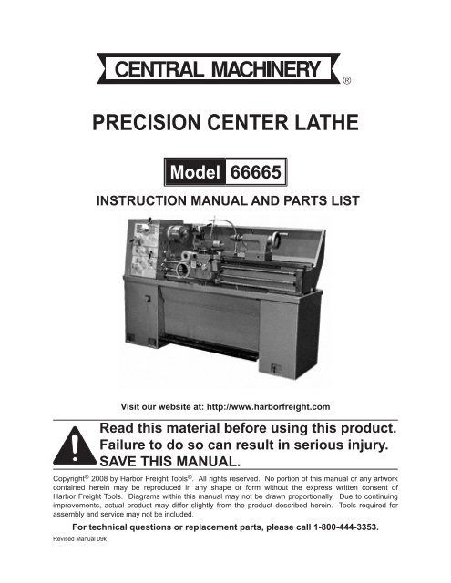
PRECISION CENTER LATHE<br />
Model 66665<br />
INSTRUCTION MANUAL AND PARTS LIST<br />
<br />
Visit our website at: http://www.harborfreight.com<br />
Read this material before using this product.<br />
Failure to do so can result in serious injury.<br />
Save this manual.<br />
Copyright © 2008 by <strong>Harbor</strong> <strong>Freight</strong> <strong>Tools</strong> ® . All rights reserved. No portion of this manual or any artwork<br />
contained herein may be reproduced in any shape or form without the express written consent of<br />
<strong>Harbor</strong> <strong>Freight</strong> <strong>Tools</strong>. Diagrams within this manual may not be drawn proportionally. Due to continuing<br />
improvements, actual product may differ slightly from the product described herein. <strong>Tools</strong> required for<br />
assembly and service may not be included.<br />
For technical questions or replacement <strong>parts</strong>, please call 1-800-444-3353.<br />
Revised Manual 09k
CONTENTS<br />
BRIEF SPECIFCATION...................................................................................................................................... 1<br />
GENERAL LAYOUT OF LATHE......................................................................................................................... 2<br />
FOUNDATION PLAN.......................................................................................................................................... 3<br />
INSTALLATION................................................................................................................................................... 4<br />
LIFITING............................................................................................................................................................. 4<br />
CLEANING......................................................................................................................................................... 4<br />
INSTALLING....................................................................................................................................................... 5<br />
LUBRICATION CHECKS.................................................................................................................................... 6<br />
CHUCKS & CHUCK MOUNTING....................................................................................................................... 7<br />
OPERATION....................................................................................................................................................... 8<br />
LATHE CONTROLS............................................................................................................................................ 8<br />
ELECTRICAL CONTROLS................................................................................................................................. 9<br />
SPEED CONTROLS........................................................................................................................................... 10<br />
THREADS & FEEDS........................................................................................................................................... 12<br />
THREADING DIAL INDICATOR.......................................................................................................................... 14<br />
APRON CONTROLS.......................................................................................................................................... 15<br />
CROSS-SLIDE & TOP SLIDE............................................................................................................................. 16<br />
TAIL STOCK........................................................................................................................................................ 17<br />
SERVICING & MAINTENANCE.......................................................................................................................... 18<br />
LATHE ALIGNMENT........................................................................................................................................... 18<br />
END GEAR TRAIN............................................................................................................................................. 20<br />
DRIVING BELTS................................................................................................................................................. 20<br />
SLIDE WAYS ATTENTION................................................................................................................................. 21<br />
CROSS-SLIDE NUT........................................................................................................................................... 21<br />
LUBRICATION.................................................................................................................................................... 22<br />
LUBRICATION DIAGRAM.................................................................................................................................. 24<br />
WIRING DIAGRAMS.......................................................................................................................................... 25<br />
ELECTRIC ELEMENT LIST................................................................................................................................ 42<br />
PARTS LIST / DIAGRAM.................................................................................................................................... 43<br />
WARRANTY........................................................................................................................................................ 73<br />
SKU 66665 For technical questions, please call 1-800-444-3353. Page 1
BRIEF SPECIFICATION<br />
Figure 1<br />
SPECIFICATIONS<br />
DESCRIPTION INCH SYSTEM METRIC SYSTEM<br />
MODEL 1340 SKU #66665 1340 SKU #66665<br />
SWING OVER BED 13” 14” 330 356<br />
SWING OVER CROSS SLIDE 7-5/8” 8-5/8” 195 220<br />
DISTANCE BETWEEN CENTERS 40” 40” 1000 1000<br />
SWING OVER GAP 19” 20” 480 506<br />
WIDTH OF BED 8-1/9” 8-1/9” 206 206<br />
NUMBERED OF SPINDLE SPEEDS 8 or 16 (2 speed motor) 8 or 16 (2 speed motor)<br />
RANGE OF SPINDLE SPEEDS 90 or 45 1800 RPM 90 or 45 1800 RPM<br />
HOLE THROUGH SPINDLE 1-1/2” 38<br />
SPINDLE NOSE D1-4 Camlock D1-4 Camlock<br />
TAPER OF SPINDLE BORE M.T. No.5 M.T. No.5<br />
TAIL STOCK QUILL TAPER M.T. No.3 M.T. No.3<br />
TAIL STOCK QUILL TRAVEL 4-1/2” 115<br />
CROSS SLIDE TRAVEL 6-1/2” 7” 165 180<br />
COMPOUND REST TRAVEL 3-1/2” 4” 90 100<br />
NUMBER OF METRIC THREADS 22 37<br />
RANGE OF METRIC THREADS 0.45-7.5 MM 0.4-7.0 MM<br />
NUMBER OF INCH THREADS 40 28<br />
RANGE OF INCH THREADS 4-112TPI 4-56TPI<br />
LONGITUDINAL FEEDS (40) 0.0012-0.0294in/rev. (42) 0.043-0.653in/rev.<br />
CROSS FEEDS (40) 0.0003-0.0100in/rev. (42) 0.015-0.220in/rev.<br />
MACHINE NET WEIGHT 1540 lb. 1650 lb. 700 kg 750 kg<br />
CROSS WEIGHT 1810 lb. 1936 lb. 820 kg 880 kg<br />
SKU 66665<br />
For technical questions, please call 1-800-444-3353.<br />
Page 1
GENERAL LAYOUT OF LATHE<br />
Figure 2<br />
1. Headstock 9. Tail-end Mounting Bolts<br />
2. Spindle 10. Lead Screw<br />
3. Top Slide 11. Chip Pan<br />
4. Saddle & Cross-slide 12. Apron<br />
5. Splash Guard 13. Foot Brake<br />
6. Tailstock 14. Head-end Mounting Bolts<br />
7. Bed 15. Gear Box<br />
8. Mounting Feet 16. End Cover<br />
SKU 66665<br />
For technical questions, please call 1-800-444-3353.<br />
Page 2
FOUNDATION PLAN<br />
Figure 3<br />
SKU 66665<br />
For technical questions, please call 1-800-444-3353.<br />
Page 3
INSTALLATION<br />
LIFTING<br />
Use the sling-chain to sling Lathe, showed as in Figure 4.<br />
Position the Saddle and Tailstock along the Bed to obtain<br />
balance.<br />
EYEBOLT<br />
CLAMPING PLATE<br />
IMPORTANT: DO NOT USE SLINGS<br />
AROUND BED AS LEADSCREW<br />
AND FEEDSHAFT MAY BE U BENT.<br />
FIGURE 4<br />
CLEANING<br />
Before operating any controls, use white spirit or kerosene to remove the anti-corrosion<br />
coating from all slideways and the endgear train.<br />
DO NOT USE CELLULOSE SOLVENTS FOR CLEANING AS THEY WILL DAMAGE<br />
THE PAINT FINISH.<br />
Machine surface becomes bright immediately after cleaning using machine oil or slideway<br />
lubricant. Use heavy oil or grease on the end gears.<br />
SKU 66665<br />
For technical questions, please call 1-800-444-3353.<br />
Page 4
INSTALLING<br />
Locate the machine on a solid foundation, allowing sufficient area all around for easy<br />
working and maintenance (see Foundation Plan). The Lathe may be used free-standing<br />
or bolted to the foundation.<br />
Free-standing: Position Lathe on foundation and adjust each of the six mounting feet to<br />
take equal share of the load. Then using an engineers precision level on the bedways<br />
(as in Figure 5), adjust the feet to level up machine. Periodically check bed level to<br />
ensure continued Lathe accuracy.<br />
Fixed installation: Position Lathe over six bolts (1/2 in. or 12 mm diam.) set into the<br />
foundation to correspond with holes in the mounting feet. Accurately level the machine<br />
as in Figure 5, then tighten hold-down bolts and recheck bed level.<br />
HEADSTOCK ENGINEERS PRECISION LEVEL TAIL STOCK<br />
BEDWAYS<br />
SADDLE &<br />
CROSS-SLIDE<br />
MOUNTING<br />
FEET<br />
MOUNTING<br />
FEET<br />
MOUNTING FEET<br />
FIGURE 5<br />
SKU 66665<br />
For technical questions, please call 1-800-444-3353.<br />
Page 5
LUBRICATION CHECKS<br />
Before operating the machine, make the following important checks:<br />
1.<br />
2.<br />
3.<br />
4.<br />
The Headstock is filled to level marked on oil sight window with Shell Tellus Oil 27.<br />
The Gearbox is filled to level marked on oil sight window with Shell Tellus Oil 27.<br />
The Carriage Apron is filled to level marked on oil sight window with Shell Tonna 33.<br />
In addition, apply light machine oil or way lubricant to the points shown on<br />
lubrication diagram which require daily oiling.<br />
1 HEADSTOCK 4<br />
2 GEARBOX<br />
3 APRON<br />
FIGURE 6<br />
SKU 66665<br />
For technical questions, please call 1-800-444-3353.<br />
Page 6
CHUCKS AND CHUCK MOUNTING<br />
WARNING: GREY-IRON CHUCKS MUST NOT BE FITTED ON THIS HIGH-SPEED<br />
LATHE. USE ONLY DUCTILE IRON CHUCKS.<br />
When fitting chucks or faceplate, first ensure that spindle and chuck tapers are scrupulously<br />
clean and that all cams lock in the correct positions. See Figure 7, it may be<br />
necessary when mounting a new chuck to re-set the Camlock Studs (A) to do this. Remove<br />
the Cap-head Locking Screws (B) and set each stud so that the Scribed Ring (C)<br />
is flush with the rear face of the chuck-with the slit lining up with the locking screw hole<br />
(See Figure 7).<br />
Now mount the chuck or faceplate on the spindle nose and tighten the three cams in<br />
turn. It must be fully tightened. If any of the cams do not tighten fully remove the chuck<br />
or faceplate and re-adjust the stud. Fit and tighten the Locking Screw (B) at each stud<br />
before remounting the chuck for work.<br />
This will assist subsequent remounting. DO NOT INTERCHANGE CHUCKS OR FACE<br />
PLATES IF LATHE WITHOUT CHECKING UP CORRECT CAMLOCKING.<br />
IMPORTANT: Take note of speed limitations when using faceplate. 10 inch faceplates<br />
should not be run at speeds greater than 770 rev/min.<br />
A<br />
C<br />
B<br />
FIGURE 7<br />
SKU 66665<br />
For technical questions, please call 1-800-444-3353.<br />
Page 7
LATHE CONTROLS<br />
1 Spindle Speed Selector<br />
2 Apron, surfacing or sliding feeds<br />
3 Gearbox, threads & feeds<br />
4 Footbrake<br />
5 Main motor rotation (forward & reverse)<br />
1<br />
OPERATION<br />
2<br />
3<br />
4<br />
5<br />
Figure 8<br />
SKU 66665<br />
For technical questions, please call 1-800-444-3353.<br />
Page 8
ELECTRIC CONTROLS<br />
The power switches are fitted on the face of electrical box in back of the bed and below<br />
the headstock. Except the main switch, all electrical controls are fitted in the front of the<br />
headstock.<br />
1.<br />
2.<br />
3.<br />
4.<br />
Move the power switch set at ON position then the indicator lamp glows.<br />
Press the GREEN button. The main drive motor can be running with a moment.<br />
(While the main motor rotation lever is set in the neutral position.)<br />
Coolant pump ON/OFF push button.<br />
Press the RED button to stop the main motor and coolant pump.<br />
HEADSTOCK<br />
1 INDICATOR LAMP<br />
2 JOG BUTTON<br />
3 COOLANT LAMP SWITCH<br />
4 EMERGENCY STOP SWITCH<br />
Figure 9<br />
SKU 66665<br />
For technical questions, please call 1-800-444-3353.<br />
Page 9
SPEED CONTROLS<br />
(2 SPEED MOTOR)<br />
Spindle Speeds: Selected by the two lever controls and a electrical switch, on the headstock<br />
and stand. The sixteen available speeds are shown directly on the data plate.<br />
While the electrical switch set at (1) position, the small lever rotated right-hand side, it<br />
provides speeds from 1800-510 RPM and rotated to left-hand side, it provides speeds<br />
from 330-90 RPM. Then move the large lever to the appropriately colored arrow aligned<br />
with the required speed on the data plate. While the electrical switch set at (2) position,<br />
it provides speeds from 900-255 RPM and 165-45 RPM. When the small lever set at<br />
upper or bottom position, the spindle is free for hand rotation.<br />
Figure 10<br />
SKU 66665<br />
For technical questions, please call 1-800-444-3353.<br />
Page 10
SPEED CONTROLS<br />
Spindle Speeds: Selected by the two lever controls on the head-stock. The eight<br />
available speeds are shown directly on the data plate. Rotate the small lever to righthand<br />
side, speeds can run from 1800-510 RPM and rotate to left-hand side, provided<br />
speeds can be from 330-90 RPM. Then move the large lever until the appropriately<br />
colored arrow is aligned with the required speed on the data plate.<br />
When the small lever set at upper or bottom position the spindle is free for hand<br />
rotation.<br />
HIGH SPEED<br />
LOW SPEED<br />
1800 RPM<br />
330 RPM<br />
510 RPM<br />
90 RPM<br />
Figure 11<br />
SKU 66665<br />
For technical questions, please call 1-800-444-3353.<br />
Page 11
THREADS AND FEEDS<br />
(METRIC GEARBOX)<br />
All the threads and feeds directly available from the gear box are shown in the data<br />
plate fitted on the front of the gear-box. The setting of control levers is shown in below.<br />
The B position of Lever (Y) can provide a range of fine threads: the A position a coarse<br />
thread range. Do not delect the range (A position) at a spindle speeds higher than 770<br />
rev min.<br />
THREADS AVAILABLE<br />
37 Metric threads 0.4 to 7.0 mm. pitch<br />
28 Whitworth threads 4 to 56 T.P.I.<br />
The endgrear train should be arranged as in<br />
the diagram shown on the date plate to suit<br />
threading requirements.<br />
Feeds: longtudinal feeds per spindle<br />
revolution range from 0.043 to 0.653mm.<br />
cross feeds per spindle revolution range from<br />
0.015 to 0.220mm.<br />
FIGURE 12<br />
SKU 66665<br />
For technical questions, please call 1-800-444-3353.<br />
Page 12
THREADS AND FEEDS<br />
(Inch Gearbox)<br />
All the threads and feeds directly available from the gear box are shown on the data<br />
plate fitted on the front of the Gear-Box. The setting of control levers is shown in Figure<br />
13.<br />
The B position of lever (Y) can provide a range of fine threads: the A position a coarse<br />
thread range. Do not delect the range (A position) at spindle speeds higher than 770<br />
rev/min.<br />
THREADS AVAILABLE<br />
40 whitworth threads 4.0 to 112 T.P.I.<br />
22 Metric threads 0.45 to 7.5 mm. Pitch<br />
The endgear train should be arranged as in<br />
the diagrams shown on the date plate to suit<br />
threading requirements.<br />
Feeds: longitudinal feeds per spindle revolution<br />
range from .0012 to .0294 in (0/0030 to 0.746<br />
mm.)<br />
Cross feeds per spindle revolution range from<br />
.0004 to .0108 in. (0.010 to 0.271 mm.)<br />
Figure 13<br />
SKU 66665<br />
For technical questions, please call 1-800-444-3353.<br />
Page 13
THREADING DIAL INDICATOR<br />
A. Whitworth Threads<br />
Located on right-hand side of the Apron on lathes having an English leadscrew. Engage the<br />
indicator pinion with the leadscrew and tighten the handnut to retain indicator in engagement.<br />
To cut threads of an even number per inch, close the leadscrew nut as ANY line on the dial<br />
passes the datum mark. To cut threads of odd number per inch, close the leadscrew nut at<br />
any NUMBERED line. Fractional threads of 1/2 or 1/4 T.P.I. may be cut by closing the nut at<br />
the SAME numbered line on each pass of the tool. This dial cannot be used with an English<br />
leadscrew to cut metric threads, or fractional threads. For these the leadscrew nut must be kept<br />
closed and the machine revered by use of the Change-over switch, after each cutting pass and<br />
tool with drawal.<br />
B. Metric Threads<br />
The thread dial used for cutting metric screw threads on lathes equipped with metric leadscrew.<br />
To provide for the various lathes equipped with metric leadscrew. To provide for the various<br />
pitches of metric threads, several gears have different numbers of teeth are mounted on the<br />
lower end of the shaft. The vertical position of the thread dial indicator is changed as required<br />
so that the correct gear for the pitch of the thread to be cut will mesh with the leadscrew. Each<br />
graduation on the dial is marked with a letter which indicates the points at which the halfnuts<br />
may be engaged for certain threads. A diagram is supplied with the thread dial to show which<br />
gear and which graduations must be used for each pitch of metric screw thread.<br />
THREADING DIAL INDICATOR<br />
SADDLE<br />
APRON<br />
Figure 14<br />
LEADSCREW<br />
Figure 15<br />
SKU 66665 For technical questions, please call 1-800-444-3353. Page 14
APRON CONTROLS<br />
In addition to handwheel traverse, the carriage can be power-operated through controls<br />
on the front of the Apron, see FIGURE 16 Knob (A). If move Handle (A) upwards,<br />
carriage would do longitudinal-feed operation. If more Handle (A) in middle position,<br />
it would do manual Operation. If move Handle (A) downwards, it would do cross-feed<br />
operation.<br />
Lever (B) is pressed downward to engage the leadscrew nut for screwcutting. To avoid<br />
-undue wear, release the nut except when screwcutting.<br />
A<br />
B<br />
FIGURE 16<br />
SKU 66665<br />
For technical questions, please call 1-800-444-3353.<br />
Page 15
CROSS-SLIDE AND TOP-SLIDE<br />
A Top-slide is fitted as standard to the Cross-slide. Carried on a rotatable base, the<br />
Cross-slide is marked 45-0-45 deg. for accurate indexing. Hand wheel dials are<br />
graduated in inch or metric divisions to suit the operating screw and nut fitted.<br />
The Cross-slide can be power operated by pulling out the hand knob (A), at one-third<br />
sliding feed per spindle revolution, or it can be hand-operated using the large-diameter<br />
dial graduated in either inch or metric division to suit the operating screw and nut fitted.<br />
TOP-SLIDE<br />
CROSS-SLIDE<br />
RELEASE<br />
A<br />
Knob Type<br />
A<br />
Lever Type<br />
Figure 17<br />
SKU 66665<br />
For technical questions, please call 1-800-444-3353.<br />
Page 16
TAIL STOCK<br />
Can be free movement along the bed by unlocking the clamp Lever (A).<br />
The tailstock barrel is locked by Lever (B).<br />
The tailstock can be set-over for production of shallow tapers or for re-aligment.<br />
Release the clamping lever and adjust Screws (S) at each side of the base to move<br />
Tailstock laterally across the base. An indication of the setover is given by the Datum<br />
Mark (C) at the Tailstock end face, as shown in Figure 18. Apply clamp lever after<br />
adjustment of set-over.<br />
FIGURE 18<br />
SKU 66665<br />
For technical questions, please call 1-800-444-3353.<br />
Page 17
SERVICE & MAINTENANCE<br />
LATHE ALIGNMENT (PART 1)<br />
With the Lathe installed and running, we recommend a check on machine alignment<br />
before commencing work. Check leveling and machine alignment at regular periods to<br />
ensure continued Lathe accuracy.<br />
Headstock check: Take a light cut-with a keen tool over a 6 in. (150mm) length of 2 in.<br />
dia. (50mm) steel bar gripped in the chuck but not supported at the free end. Micrometer<br />
readings at each end of the turned length (at A and B of Figure 19) should be the<br />
same.<br />
To correct a difference in readings, slacken and release the four headstock hold-down<br />
screws (J) shown in Figure 19 and adjust the set-over pad (K) beneath the headstock.<br />
Then tighten all screws. After adjustment, repeat the test -cut/micrometer-reading until<br />
micrometer readings are identical so that machine cutting will be absolutely parallel.<br />
HEADSTOCK<br />
SKU 66665<br />
J<br />
FIGURE 19<br />
For technical questions, please call 1-800-444-3353. Page 18
LATHE ALIGNMENT (PART 2)<br />
Tailstock check: Using a 12 in. (305mm) ground steel bar fitted between centers of<br />
Headstock and Tailstock. Check the alignment by fitting a dial-test indicator to the<br />
topslide and traversing the center line of the bar.<br />
To correct error, release the Tailstock Clamp Lever and adjust the two set-over screws<br />
provided. Continuously check and correct until the alignment is perfect.<br />
TAILSTOCK<br />
HEADSTOCK<br />
TOPSLIDE<br />
TAILSTOCK CLAMP LEVER<br />
SET-OVER SCREWS<br />
Figure 20<br />
SKU 66665<br />
For technical questions, please call 1-800-444-3353.<br />
Page 19
END GEAR TRAIN<br />
Drive from Headstock to Gear-box is transmitted<br />
through a gear train enclosed by the<br />
Headstock end-guard. Intermediate gears are<br />
carried on an Adjustable Swing Frame (M).<br />
HEADSTOCK<br />
Gears must be thoroughly cleaned before<br />
fitting and backlash maintained at .005 in.<br />
(.127mm). Lubricate gears regularly with thick<br />
oil or grease.<br />
Figure 21<br />
DRIVING BELTS<br />
PULLEY<br />
To alter belt tension, remove the coverplate in<br />
back of the Headstock Block and adjust the<br />
two Screws (X) on the hinged motor platform.<br />
Ensure that the motor is correctly aligned with<br />
the Lathe Axis.<br />
Light finger pressure at a point midway between<br />
Motor and Headstock Pulleys should<br />
produce about 3/4 in. (19mm) movement of<br />
each belt when under correct tension.<br />
BELT<br />
MOTOR<br />
PULLEY<br />
X<br />
SKU 66665<br />
For technical questions, please call 1-800-444-3353.<br />
Figure 22<br />
Page 20
SLIDE WAYS ATTENTION<br />
Tapered gib strips are fitted to<br />
slideways of saddle cross-slide and top<br />
(compound) slides so that any slackness<br />
which may develop can be rectified.<br />
Ensure that slideways are thoughly<br />
cleaned and lubricated before<br />
attempting adjustment. Then reset the<br />
gibs by slackening the rear gib screw<br />
and tightening the front screw. Check<br />
constantly for smooth action throughout<br />
full slide travel. Avoid over-adjustment<br />
which can result in increased wear-rate<br />
and stiff or jerky action.<br />
Figure 23<br />
GIB ADJUSTERS<br />
CAP-HEAD SCREW<br />
CROSS-SLIDE NUT<br />
This is adjustable for elimination of<br />
slackness which may develop in service.<br />
Reduce back-lash by the cap-head<br />
screw in the rear of the nut. Then make<br />
only small adjustment by the cap-head<br />
screw. Before operating the cross-slide,<br />
check several times by hand to be sure<br />
of smooth operation throughout travel.<br />
NUT<br />
Figure 24<br />
SKU 66665<br />
For technical questions, please call 1-800-444-3353.<br />
Page 21
LUBRICATION (PART 1)<br />
The headstock and gearbox are splash-lubricated from an internal reservoir of oil (Shell<br />
Tellus 27). Check the oil level constantly to the mark on the oil sight window in the<br />
front end face of the headstock and gearbox. A weekly check is recommended. The<br />
oil needs to be changed every year. Oil through a filler cap in the top of the headstock<br />
and gearbox is covered by the end-guard. Drain from a drain plug in the bottom of the<br />
headstock and gearbox.<br />
The Apron is lubricated from an internal reservior of oil. The oil sight window is in the<br />
front of the Apron. A filler cap is in the top of the Saddle. Refill the reservoir to the level<br />
of the oilsight with Shell Tonna oil 33. The Apron can be drained by unscrewing a hexheaded<br />
drain plug in the bottom.<br />
FILLER CAP HEADSTOCK APRON<br />
FILLER CAP<br />
DRAIN PLUG<br />
GEARBOX<br />
DRAIN PLUG<br />
Figure 25<br />
SKU 66665<br />
For technical questions, please call 1-800-444-3353.<br />
Page 22
LUBRICATION (PART 2)<br />
In addition, oil gun is provided for the Saddle, Cross-slide, Cross-slide Nut and Top-<br />
Slide (compound slide) to oil. Leadscrew using a oil gun can be oiled with light machine<br />
oil or way lubricant.<br />
On the Tailstock, oil points are provided for daily attention from a standard oil can.<br />
It is recommended that all slideways, leadscrew and feed shaft are cleaned off (a bristle<br />
paint brush is useful for this) and lightly oiled after each period of work.<br />
NOTE: Using incorrect grades of oil can cause damage.<br />
OILER POINTS<br />
OILER POINTS<br />
OILER<br />
POINTS<br />
OILER POINTS<br />
Figure 26<br />
SKU 66665<br />
For technical questions, please call 1-800-444-3353.<br />
Page 23
LUBRICATION DIAGRAM<br />
Figure 27<br />
A - TOP-OFF EVERY WEEK<br />
B - OIL EVERY DAY<br />
SKU 66665<br />
For technical questions, please call 1-800-444-3353.<br />
Page 24
WIRING DIAGRAMS<br />
380V/50HZ/3P<br />
400V/50HZ/3P<br />
420V/50HZ/3P<br />
220V/50HZ/3P<br />
220V/60HZ/3P<br />
SKU 66665<br />
For technical questions, please call 1-800-444-3353.<br />
Page 25
220V/50HZ/3P<br />
220V/60HZ/3P<br />
SKU 66665<br />
For technical questions, please call 1-800-444-3353.<br />
Page 26
380V/50HZ/3P<br />
400V/50HZ/3P<br />
420V/50HZ/3P<br />
220V/50HZ/3P<br />
220V/60HZ/3P<br />
SKU 66665<br />
For technical questions, please call 1-800-444-3353.<br />
Page 27
220V/50HZ/3P<br />
220V/60HZ/3P<br />
SKU 66665<br />
For technical questions, please call 1-800-444-3353.<br />
Page 28
380V/50HZ/3P<br />
400V/50HZ/3P<br />
420V/50HZ/3P<br />
SKU 66665<br />
For technical questions, please call 1-800-444-3353.<br />
Page 29
ELECTRIC PANEL CONNECTION<br />
220V/50HZ/3P<br />
220V/60HZ/3P<br />
SKU 66665<br />
For technical questions, please call 1-800-444-3353.<br />
Page 30
ELECTRIC PANEL CONNECTION<br />
220V/50HZ/3P<br />
220V/60HZ/3P<br />
SKU 66665<br />
For technical questions, please call 1-800-444-3353.<br />
Page 31
THE CONNECTION BETWEEN ELECTRIC PANEL AND OUTISDE ELECTRIC COMPONENTS.<br />
380V/50HZ/3P<br />
400V/50HZ/3P<br />
420V/50HZ/3P<br />
SKU 66665<br />
For technical questions, please call 1-800-444-3353.<br />
Page 32
THE CONNECTION BETWEEN ELECTRIC PANEL AND OUTISDE ELECTRIC COMPONENTS.<br />
220V/50HZ/3P<br />
220V/60HZ/3P<br />
SKU 66665<br />
For technical questions, please call 1-800-444-3353.<br />
Page 33
THE CONNECTION BETWEEN ELECTRIC PANEL AND OUTISDE ELECTRIC COMPONENTS.<br />
220V/50HZ/3P<br />
220V/60HZ/3P<br />
SKU 66665<br />
For technical questions, please call 1-800-444-3353.<br />
Page 34
ELECTRIC PANEL<br />
SKU 66665<br />
For technical questions, please call 1-800-444-3353.<br />
Page 35
SKU 66665<br />
For technical questions, please call 1-800-444-3353.<br />
Page 36
INPUT CABLE BOX<br />
SKU 66665<br />
For technical questions, please call 1-800-444-3353.<br />
Page 37
SKU 66665<br />
For technical questions, please call 1-800-444-3353.<br />
Page 38
SKU 66665<br />
For technical questions, please call 1-800-444-3353.<br />
Page 39
SKU 66665<br />
For technical questions, please call 1-800-444-3353.<br />
Page 40
SKU 66665<br />
For technical questions, please call 1-800-444-3353.<br />
Page 41
ELECTRIC ELEMENT LIST<br />
SYMBOL NAME TYPE QTY NOTE<br />
M1 MOTOR YD112M-8/4<br />
M2 MOTOR AB-12TH<br />
KM1 AC CONTRACTOR CJX5-9 AC24V 50/60HZ<br />
CJX5-22 AC24V 50/60HZ<br />
3PH<br />
1PH<br />
KM2 AC CONTRACTOR CJX5-12 AC24V 50/60HZ<br />
380V/400V/420V<br />
CJX5-22 AC24V 50/60HZ<br />
KM3 AC CONTRACTOR CJX5-12 AC24V 50/60HZ<br />
CJX5-22 AC24V 50/60HZ<br />
KM4 AC CONTRACTOR CJX5-12 AC24V 50/60HZ<br />
TC TRANSFORMER JBK3-100<br />
PRIMARY: 0~220V~390V~400V~420V<br />
SECONDARY: 0~24V, 0~24V~29V<br />
FU1 FUSE BLF-1 2A<br />
FU2 FUSE BLF-1 2A<br />
FR1 HEATING DEVICE RELAY JRS5-20/F<br />
FR2 HEATING DEVICE RELAY JRS5-12/Z<br />
SA1 SELECTOR SWITCH HZ5-20/4 L02<br />
SA2 SELECTOR SWITCH HZ5-20/4 M08<br />
SA3 COOLANT LAY3-10X/2<br />
SB1 RESET LAY3-01ZS/1<br />
SB2 JOGGING LAY3-10<br />
HL INDICATOR LAMP AD11-25 AC24V<br />
SQ1 JIGGLE SWITCH LXW5-11N1<br />
SQ2 JIGGLE SWITCH LXW5-11Q2<br />
SQ3 JIGGLE SWITCH LXW5-11D1<br />
SQ4 JIGGLE SWITCH LXW5-11D1<br />
EL MACHINE LIGHT AC24V 40W<br />
220V<br />
380V/400V/420V<br />
220V<br />
SKU 66665<br />
For technical questions, please call 1-800-444-3353.<br />
Page 42
PARTS LIST - HEADSTOCK<br />
Part No. Description Specification QTY<br />
1006 Head Stock 1<br />
1014 Shifter Shaft 1<br />
Screw GB77 M8×12 2<br />
Spring GB2089 1×5×22 2<br />
Ball GB308 φ6 2<br />
1014 Shifter Shaft 1<br />
Screw GB77 M6 X 6 2<br />
1027 Gear 1<br />
Collar GB894.2 25 1<br />
Bearing GB276 E104 1<br />
Collar GB894.2 20 1<br />
Hex Screw GB70 M6×35 10<br />
1028 Seal 1<br />
1029 Cover 1<br />
1030 Gear 1<br />
Collar GB894.2 25 1<br />
Bearing GB276 104 1<br />
Collar GB894.2 20 2<br />
Seal SD25×40×10 1<br />
Hex Screw GB70 M6×12 3<br />
1031 Gear 1<br />
1032 Cover 1<br />
1033 Gear 1<br />
1034 Cover 1<br />
1050 Handle Block 1<br />
1052 Seal 1<br />
Screw GB78 M5×6 1<br />
1055 Cover 1<br />
Hex Screw GB70 M6×12 2<br />
1055 Cover 1<br />
Hex Screw GB70 M6 x 12 2<br />
1056 Washer 1<br />
1056 Washer 1<br />
Hex Screw GB70 M6 x 12 1<br />
1057 Handle Block 1<br />
1058 Handle 1<br />
1059 Spring 2<br />
1061 Shifter Arm 1<br />
Pin GB879 5×30 1<br />
1062 Shifter Arm 1<br />
Key GB1096 5×18 1<br />
1063 Shifter 1<br />
1064 Shaft 1<br />
Screw GB77 M12×12 2<br />
1065 Shifter 1<br />
Part No. Description Specifications QTY<br />
1067 Screw 2<br />
1068 Block 1<br />
Screw GB5781 M10×40 2<br />
Hex Screw GB70 M12×30 2<br />
1069 Shifter Shaft 1<br />
1070 Cover 1<br />
1071 Shifter Arm 1<br />
Pin GB879 5×30 1<br />
1072 Shaft 1<br />
O Seal GB1235.1 15×2.65 2<br />
1073 Shifter Arm 1<br />
Pin GB119 10×20 1<br />
O Seal GB1235.1 12.5×2.65 1<br />
1076 Gear Shaft 1<br />
O Seal GB1235.1 26.5×2.65 1<br />
1077 Shifter Shaft 1<br />
Key GB1096 4×10 1<br />
1078 Handle 1<br />
1079 Handle Sleeve 1<br />
Hex Screw GB70 M12×35 2<br />
Hex Screw GB70 M6×12 1<br />
O Seal GB1235.1 15×2.65 4<br />
1079 Handle Sleeve 2<br />
1080 Handle 1<br />
1080 Handle 1<br />
1081 Screw 1<br />
Ball GB308 φ9 2<br />
1082 Shifter 1<br />
1082 Shifter 1<br />
1083 Shifter Arm 1<br />
Screw GB78 M6×6 1<br />
Pin GB879 5×30 1<br />
1084 Gear 1<br />
Pin GB879 5×30 1<br />
1085 Positioning Block 1<br />
Screw GB78 M5×15 1<br />
Pin GB879 5×30 1<br />
1086 IV Shaft 1<br />
Bearing GB276 105 1<br />
Collar GB894.2 25 1<br />
Collar GB894.2 25 1<br />
1091 Handle Block 1<br />
1091 Handle Block 1<br />
SKU 66665<br />
For technical questions, please call 1-800-444-3353.<br />
Page 43
DIAGRAM - HEADSTOCK<br />
SKU 66665<br />
For technical questions, please call 1-800-444-3353.<br />
Page 44
PARTS LIST - HEADSTOCK<br />
Part No. Description Specification QTY Part No. Description Specifications QTY<br />
Hex Screw GB70 M8×20 1 1035 Ⅴ Shaft 1<br />
1001 Bush 1<br />
Key GB1096 6×90 1<br />
1002 Pulley 1 1036 Gear Combination 1<br />
1003 Brake Wheel 1 1037 Cover 1<br />
1004 Brake Shaft 1 1037 Cover 1<br />
Collar GB894.2 12 1 1038 Cover 1<br />
Seal SD25x45x10 1 1038 Cover 1<br />
Hex Screw GB70 M6×20 3<br />
Hex Screw GB70 M6×16 3<br />
Collar GB894.2 12 1 1039 Gear 1<br />
1005 Cover 1<br />
Collar GB894.2 38 1<br />
1007 Seal 1 1040 Seal 1<br />
Collar GB894.2 25 1<br />
Bearing GB276 E204 1<br />
Bearing GB276 E205 1 1040 Seal 2<br />
Key GB1096 8×20 1<br />
Bearing GB276 204 1<br />
Key GB1096 8×50 1 1041 Gear Combination 1<br />
1008 Gear 1 1042 Ⅳ Shaft 1<br />
1009 Gear 1<br />
Screw GB78 M5×16 3<br />
1010 Cover 1<br />
Key GB1096 5×16 1<br />
1011 Gear 1 1043 Gear 1<br />
1012 Gear 1<br />
Collar GB894.2 55 1<br />
Bearing GB276 E204 2 1044 Nut 1<br />
Collar GB894.2 20 1<br />
Bearing GB297 D7210 1<br />
1013 I Shaft 1<br />
Collar GB894.2 50 1<br />
1016 Gear 1 1045 Cover 1<br />
Key GB1096 8×28 1 1047(1046) Gear 1<br />
Bearing GB276 105 1 1047 Seal 1<br />
Collar GB893.1 47 1<br />
Hex Screw GB70 M5×14 2<br />
1017 Cover 1 1048 Gear 1<br />
O Seal GB1235 40×3.55 1 1049 Gear 1<br />
Hex Screw GB70 M6×16 3 1051 Gear 1<br />
1018 Ⅱ Shaft 1<br />
Key GB1096 8×50 1<br />
1019 Gear 1 1053 Cover 1<br />
1020 Spindle 1<br />
Collar GB894.2 50 1<br />
Key GB1096 8×56 1 1053 Collar 1<br />
1021 Cover 1<br />
Bearing GB276 204 1<br />
Hex Screw GB70 M6×25 3<br />
Collar GB894.2 20 1<br />
Key GB1096 8×32 1<br />
Collar GB894.2 37 1<br />
1022 Seal 1 1054 Shaft 1<br />
1023 Cover 1 1087 Eccantric Shaft 3<br />
Bearing GB297 D7511 1<br />
GB1235.1<br />
O Seal<br />
1<br />
23.6×2.65<br />
1024 Gear 1<br />
1088 Pin 3<br />
1025 Gear 1<br />
GB2089<br />
Spring<br />
3<br />
1026 Cover 1<br />
0.6×16×22<br />
O Seal GB1235.1 19×2.65 1<br />
Hex Screw GB70 M8×16 3<br />
Hex Screw GB70 M6×20 3<br />
7060 Shaft 1<br />
Pin GB879 5×25 1<br />
SKU 66665<br />
For technical questions, please call 1-800-444-3353.<br />
Page 45
DIAGRAM - HEADSTOCK<br />
SKU 66665<br />
For technical questions, please call 1-800-444-3353.<br />
Page 46
DIAGRAM - HEADSTOCK<br />
SKU 66665<br />
For technical questions, please call 1-800-444-3353.<br />
Page 47
PARTS LIST - GEARBOX<br />
Part No. Description Specification QTY<br />
3004 Gear Box 1<br />
Pin GB879 5×28 2<br />
Pin GB879 5×28 2<br />
Hex Screw GB70 M8×25 2<br />
Pin GB879 5×20 2<br />
Hex Screw GB70 M8×40 2<br />
Oil Indicator GB71160 20 1<br />
3005 Cover 1<br />
Screw GB819 M4×10 8<br />
3009 Cover 1<br />
3036 Shifter 1<br />
3037 Gear 1<br />
3038 Rack Gear 1<br />
Hex Screw GB70 M6×10 2<br />
3039 Shaft 1<br />
3040 Pressing Plate 1<br />
Key GB1096 4×10 1<br />
Pin GB879 5×20 2<br />
3041 Handle Wheel 2<br />
3042 Washer 2<br />
Hex Screw GB70 M6×16 2<br />
3043 Sign 2<br />
Screw GB818 M3×6 6<br />
3044 Positioning Rod 1<br />
Screw GB78 M6×8 1<br />
3046 Key 3<br />
3047 Cover 1<br />
3048 Positioning Block 1<br />
Part No. Description Specification QTY<br />
3049 Seal 2<br />
3050 Pressing Plate 1<br />
3051 Swivel Arm 1<br />
3052 Shaft 1<br />
Screw GB78 M6×8 2<br />
3053 Shifter 1<br />
3054 Swivel Arm 1<br />
3055 Shaft 1<br />
Pin GB879 5×20 2<br />
Screw GB79 M6×8 1<br />
3056 Handle 1<br />
3057 Sign 1<br />
Screw GB77 M8×8 4<br />
Spring GB2089 0.8×5×25 4<br />
Ball GB308 φ6.5 4<br />
3058 Handle Block 1<br />
3060 Pressing Plate 1<br />
Key GB1096 4×10 3<br />
3061 Pressing Plate 1<br />
Screw GB819 M5×10 2<br />
3062 Shifter Shaft 1<br />
Key GB1096 4×10 1<br />
3063 Gear 1<br />
3065 Shaft 1<br />
Collar GB893.1 19 1<br />
Bearins GB276 1000098 1<br />
3066 Handle Sleeve 1<br />
3067 Screw ZG3/8” 2<br />
SKU 66665<br />
For technical questions, please call 1-800-444-3353.<br />
Page 48
DIAGRAM - GEAR BOX<br />
SKU 66665<br />
For technical questions, please call 1-800-444-3353.<br />
Page 49
PARTS LIST - GEAR BOX - FOR SAE THREADS<br />
Part No. Description Specification QTY<br />
2004 Washer 1<br />
2006 Change Gear 1<br />
Hex Screw GB70 M6×20 3<br />
3001a Ⅱ Shaft 1<br />
Bearing GB276 7000102 1<br />
3002 Seal 2<br />
Bearing GB276 104 1<br />
Hex Screw GB70 M6×16 1<br />
Key GB1096 5×14 1<br />
3006a-1 Shaft Cover 1<br />
Bearing GB276 103 1<br />
Collar GB894.2 20 1<br />
3006a-2 Shaft Cover 1<br />
3008 Gear 1<br />
3010 Shaft Cover 1<br />
3011 Gear 1<br />
3012 Nut 2<br />
Bearing GB301 8104 1<br />
3013 Cover 1<br />
Hex Screw GB70 M6×16 3<br />
Bearing GB301 8104 1<br />
Key GB1096 5×14 2<br />
3014 Shaft 1<br />
3015a I Shaft 1<br />
Key GB1096 5×75 1<br />
3016 Shifter Cover 1<br />
O Seal GB1235.1 15×2.65 1<br />
Hex Screw GB70 M6×16 3<br />
Shaft Cover GB301 8104 1<br />
3017 Shaft 1<br />
Key GB1096 5×14 1<br />
Key GB1096 6×14 1<br />
Collar GB894.2 15 1<br />
Bearing GB276 202 1<br />
Part No. Description Specification QTY<br />
3018 Double Gear 1<br />
Collar GB894.2 20 1<br />
Bearing GB276 202 1<br />
3019 Gear 1<br />
3020 Seal 2<br />
3020 Seal 2<br />
3021 Gear 1<br />
Collar GB894.2 15 1<br />
3022 Gear 1<br />
Bearing GB276 202 1<br />
Bearing GB276 1000804 1<br />
3023a Gear 1<br />
Bearing GB276 202 1<br />
3024 Gear 1<br />
3025 Gear 1<br />
3026 Gear 1<br />
3027 Gear 1<br />
3028 Gear 1<br />
3029 Gear 1<br />
3030 Gear 1<br />
3031 Gear 1<br />
3032 Seal 1<br />
3032 Seal 1<br />
3033a IV Shaft 1<br />
Collar GB894.1 20 1<br />
3034 Bearing Cover 1<br />
Hex Screw GB70 M6×16 2<br />
3034 Bearing Cover 1<br />
Hex Screw GB70 M6×16 2<br />
Bearing GB276 103 1<br />
3035 Cover 1<br />
3064 Gear 1<br />
Collar GB893.1 32 2<br />
SKU 66665<br />
For technical questions, please call 1-800-444-3353.<br />
Page 50
DIAGRAM - GEAR BOX - FOR SAE THREADS<br />
SKU 66665<br />
For technical questions, please call 1-800-444-3353.<br />
Page 51
PARTS LIST - GEAR BOX - FOR METRIC THREADS<br />
Part No Description Specifications QTY<br />
Collar GB894.2 13 1<br />
Bearing GB276 202 1<br />
2004 Washer 1<br />
2006 Change Gear 1<br />
Hex Screw GB70 M6×20 3<br />
3001 Ⅱ Shaft 1<br />
Key GB1096 5×75 1<br />
3002 Seal 1<br />
Bearing GB276 104 1<br />
Hex Screw GB70 M6×16 1<br />
Key GB1096 5×14 1<br />
3006 Shaft Cover 1<br />
Bearing GB276 7000102 1<br />
3007 Gear 1<br />
Bearing GB276 103 1<br />
Key GB1096 5×8 1<br />
3010 Shifter Cover 1<br />
3011 Gear 1<br />
3012 Nut 2<br />
Bearing GB301 8104 1<br />
3013 Cover 1<br />
Hex Screw GB70 M6×16 3<br />
Bearing GB301 8104 1<br />
Key GB1096 5×14 2<br />
3014 Shaft 1<br />
3015 I Shaft 1<br />
Collar GB894.2 20 1<br />
3016 Shaft Cover 1<br />
O Seal GB1235.1 15×2.65 1<br />
Hex Screw GB70 M6×16 3<br />
Bearing GB301 8104 1<br />
3017 Shaft 1<br />
Key GB1096 5×14 1<br />
Key GB1096 6×14 1<br />
Part No. Description Specifications QTY<br />
3018 Doulole Gear 1<br />
Collar GB894.2 20 1<br />
Bearing GB276 202 1<br />
3019 Gear 1<br />
3020 Seal 1<br />
3020 Seal 2<br />
3021 Gear 1<br />
Collar GB894.2 15 1<br />
3022 Gear 1<br />
Bearing GB276 202 1<br />
3023 Gear 1<br />
Collar GB894.2 20 1<br />
Bearing GB276 1000804 2<br />
3024 Gear 1<br />
3025 Gear 1<br />
3026 Gear 1<br />
3027 Gear 1<br />
3028 Gear 1<br />
3029 Gear 1<br />
3030 Gear 1<br />
3031 Gear 1<br />
3032 Seal 1<br />
3032 Seal 2<br />
3033 IV Shaft 1<br />
Bearing GB276 202 1<br />
3034 Bearing Cover 1<br />
Hex Screw GB70 M6×16 2<br />
Bearing GB276 103 1<br />
3034 Bearing Cover 1<br />
Hex Screw GB70 M6×16 2<br />
3035 Bearing Cover 1<br />
3064 Gear 1<br />
Collar GB893.1 32 2<br />
SKU 66665<br />
For technical questions, please call 1-800-444-3353.<br />
Page 52
DIAGRAM - GEAR BOX FOR METRIC THREADS<br />
SKU 66665<br />
For technical questions, please call 1-800-444-3353.<br />
Page 53
PARTS LIST - APRON - LEFT HAND, LEVER TYPE<br />
Part No. Description Specification QTY<br />
Screw GB78 M6×25 1<br />
4001 Handle Sleeve 1<br />
4002 Handle Shaft 1<br />
4003 Handle Wheel 2<br />
4004 Nut 1<br />
Ball GB308 φ6 2<br />
4005 Spring 2<br />
4006 Scale Plate 1<br />
Hex Screw GB70 M6×16 3<br />
4007 Shaft Cover 1<br />
Key GB1096 5×15 1<br />
4008 Apron 1<br />
4009 Gear Shaft 1<br />
4010 Gear 1<br />
4011 Gear Shaft 1<br />
4012 Washer 1<br />
Pin GB879 5×30 1<br />
4012 Washer 1<br />
Collar GB894.2 16 1<br />
O Seal GB1235 17×1.8 1<br />
4013 Brass Cover 1<br />
Double<br />
4014 Shaft 1<br />
4015 Wheel 1<br />
Hex Screw GB70 M6×10 2<br />
4016a 4016 Half Nut 1<br />
4017 Half Nut Block 1<br />
Hex Screw GB70 M6×16 2<br />
4018 Pin 2<br />
4019 Pressing Plate 1<br />
Screw GB78 M6×10 3<br />
Screw GB80 M8×8 1<br />
4020 Half Nut Shaft 1<br />
4021 Cam 1<br />
4022 Handle Sleeve 1<br />
4022 Handle Sleeve 1<br />
4023 Handle 1<br />
Pin GB879 5×35 1<br />
Screw GB80 M6×8 1<br />
Part No. Description Specifications QTY<br />
4024 Handle Blook 1<br />
Pin GB879 5×50 1<br />
Oil Sign GB1160 12 1<br />
4025 Stop 1<br />
Hex Screw GB70 M6×12 2<br />
Hex Screw GB70 M6×16 2<br />
4026 Handle 1<br />
4027 Gear Shaft 1<br />
4030 Gear Shaft 1<br />
Screw GB80 M6×8 2<br />
4031 Shifter Block 1<br />
4032 Gear Shaft 1<br />
4033 Oil Cover 1<br />
Collar GB894.2 16 1<br />
4035 Cover 1<br />
Hex Screw GB70 M6×46 3<br />
4036 Spring 1<br />
Ball GB308 φ6 1<br />
Hex Screw GB70 M8×40 2<br />
4048 Spring 1<br />
Ball GB308 φ6 1<br />
4049 Shaft 1<br />
Key GB1096 4×15 1<br />
Pin GB879 5×35 1<br />
4050 Gear 1<br />
Screw GB80 M6×6 1<br />
4051 Shaft Cover 1<br />
4052 Gear 1<br />
Collar GB894.2 16 1<br />
4053 Worm Shaft 1<br />
Pin GB879 3×5 2<br />
4054 Bushing 1<br />
Key GB1096 5×56 1<br />
4054 Bushing 1<br />
Hex Screw GB70 M6×16 2<br />
4055 Screw ZG3/8” 1<br />
SKU 66665<br />
For technical questions, please call 1-800-444-3353.<br />
Page 54
DIAGRAM - APRON - LEFT HAND, LEVER TYPE<br />
SKU 66665<br />
For technical questions, please call 1-800-444-3353.<br />
Page 55
DIAGRAM - APRON - LEFT HAND, LEVER TYPE<br />
SKU 66665<br />
For technical questions, please call 1-800-444-3353.<br />
Page 56
PARTS LIST - SADDLE CROSS SLIDE, TELESCOPIC TYPE<br />
Part No. Description Specification QTY<br />
5001 Cover 1<br />
Bearing GB301 8101 1<br />
Hex Screw GB70 M6×30 2<br />
5002 Cover 1<br />
Screw GB78 M8×8 1<br />
Bearing GB301 8101 1<br />
5003 Collar 1<br />
5003 Collar 1<br />
Oil Cup GB1155 6 1<br />
Rivet GB827 2×8 2<br />
5004 Pressing Plate 1<br />
5005 Gib 1<br />
5007a 5007Screw 1<br />
Hex Screw GB70 M6×12 1<br />
5008a 5008 Nut 1<br />
Screw GB819 M3×5 2<br />
Key GB1096 4×20 1<br />
5009 Bush 1<br />
Oil Cup GB1155 8 1<br />
5010 Pressing Plate 2<br />
Screw GB70 M8×20 4<br />
5011 Shaft 1<br />
5012 Gear Shaft 1<br />
Key GB1096 4×20 1<br />
5013 Support 1<br />
Hex Screw GB70 M6×20 1<br />
Bearing GB301 8102 2<br />
5014 Collar 1<br />
Screw GB818 M5×10 3<br />
5015a 5015Dial 1<br />
Ball GB308 φ6 3<br />
Part No. Description Specification QTY<br />
5016 Nut 2<br />
5017 Handle Shaft 1<br />
5018 Handle Sleeve 1<br />
Screw GB78 M6×25 1<br />
5019 Handle Sleeve 1<br />
5020 Cross Slide 1<br />
5021 Screw 1<br />
5021 Screw 1<br />
Hex Screw GB70 M6×20 1<br />
5024 Screw 1<br />
Screw GB818 M5×8 6<br />
5024 Screw 1<br />
Nut GB6172 M6 2<br />
5034 Gib 1<br />
5042 Oil Cover 1<br />
Screw GB818 M5×10 8<br />
5043 Handle Block 1<br />
5044 Rod 1<br />
5045 Handle 1<br />
Nut GB6170 M6 3<br />
Screw GB78 M6×20 3<br />
5051 Spring 3<br />
5052 Gign 1<br />
5053 Block 1<br />
5054 Block 1<br />
5055 Baffle 1<br />
5056 Baffle 1<br />
Oil Cup GB1155 8 4<br />
Hex Screw GB70 M6×20 1<br />
SKU 66665<br />
For technical questions, please call 1-800-444-3353.<br />
Page 57
DIAGRAM - SADDLE CROSS SLIDE TELESCROPIC TYPE<br />
SKU 66665<br />
For technical questions, please call 1-800-444-3353.<br />
Page 58
PARTS LIST - top slide, tool post<br />
Part No. Description Specification QTY<br />
Screw GB83 M10×50 8<br />
5016 Nut 1<br />
Screw GB78 M6×25 1<br />
5022 Topslide Block 1<br />
5023 Gib 1<br />
Screw GB70 M8×16 2<br />
Screw GB80 M6×16 1<br />
5024 Screw 2<br />
5025 Top Slide 1<br />
Hex Screw GB70 M6×20 1<br />
5026 Spring 1<br />
5027 Pin 1<br />
5028 Shaft 1<br />
5029 Todpost 1<br />
5030 Washer 1<br />
5031 Handle Block 1<br />
5032 Handle 1<br />
5033 Handle Sleeve 1<br />
5036 T Plate 1<br />
5037a 5037 Screw 1<br />
5038a 5038 Nut 1<br />
Key GB1096 4×14 1<br />
5039 Support 1<br />
Hex Screw GB70 M6×20 4<br />
Bearing GB301 8103 2<br />
5040a 5040 Dial 1<br />
Ball GB308 φ6 2<br />
5041 Handle Wheel 1<br />
5048 Handle 1<br />
5048 Handle 1<br />
Hex Screw GB70 M5×40 1<br />
5049 Handle 1<br />
5050 Spring 2<br />
5057 Adjust Artide 1<br />
Oil Cup GB1155 8 1<br />
SKU 66665<br />
For technical questions, please call 1-800-444-3353.<br />
Page 59
DIAGRAM - TOP SLIDE, TOOL POST<br />
SKU 66665<br />
For technical questions, please call 1-800-444-3353.<br />
Page 60
PARTS LIST - TAIL STOCK<br />
Part No. Description Specification QTY<br />
8001 Tailstock 1<br />
Oil Cup GB1155 10 2<br />
8002 Tailstock Base 1<br />
8003 Screw 2<br />
8004 Gib 1<br />
Hex Screw GB70 M8×45 2<br />
8005 Handle 2<br />
8006 Shaft Wheel 1<br />
8007 Handle Sleeve 1<br />
8008 Handle Shaft 1<br />
8009 Screw 1<br />
Screw GB78 M6×25 1<br />
8011a 8011 Dial 1<br />
Hex Screw GB70 M6×20 3<br />
8013 Cover 1<br />
Bushing GB301 8103 1<br />
Key GB1096 4×20 1<br />
8014a 8014 Nut 1<br />
Hex Screw GB70 M6×16 2<br />
8015 Quill 1<br />
8016a 8016 Screw 1<br />
8018 Pin 1<br />
8020 Locking Shaft 1<br />
Pin GB879 5×12 1<br />
8021 Hanging Block 1<br />
8022 Clamping Block 1<br />
Washer GB95 12 2<br />
Screw GB5782 M12×75 1<br />
8023 Locking Shaft 1<br />
Pin GB879 5×12 1<br />
Screw GB77 M6×16 1<br />
Nut GB41 M6 1<br />
8024 Handle Sleeve 1<br />
SKU 66665<br />
For technical questions, please call 1-800-444-3353.<br />
Page 61
DIAGRAM - TAIL STOCK<br />
SKU 66665<br />
For technical questions, please call 1-800-444-3353.<br />
Page 62
PARTS LIST - BED & SHAFTS<br />
Part No. Description Specification QTY<br />
Screw GB5781 M12×50 6<br />
7001 Bedway 1<br />
Screw GB70 M6×25 6<br />
Pin GB879 6×35 4<br />
7002 Sign 1<br />
7003 Collar 1<br />
Screw GB79 M6×10 1<br />
7004 Gap 1<br />
Screw GB70 M10×40 4<br />
Nut GB6172 M8 2<br />
Pin GB881 8×60 2<br />
7005 Rack Gear 1<br />
Pin GB879 5×35 2<br />
7006a 7006Screw 1<br />
7007 Feeding Red 1<br />
7008 Operating Red 1<br />
Screw GB818 M4×10 4<br />
Screw GB79 M6×16 1<br />
7010 Support 1<br />
Screw GB70 M6×16 2<br />
Screw GB78 M6×20 1<br />
Nut GB41 M6 2<br />
7013 Support 1<br />
Oil Cup GB1155 10 1<br />
Screw GB70 M8×55 2<br />
Pin GB117 5×60 2<br />
7032 Cover 1<br />
Part No. Description Specification QTY<br />
7033 Switch Box 1<br />
7037 Switch Box 1<br />
Screw GB70 M8×25 2<br />
7038 Handle 1<br />
7042 Cover 1<br />
Screw GB73 M6×12 2<br />
Screw GB818 M6×20 2<br />
7043 Spring 1<br />
Ball GB308 φ6 1<br />
7044 Collar 1<br />
Ball GB308 φ6 2<br />
7045 Pin 1<br />
7046 Shifter 1<br />
Pin GB879 3×20 1<br />
7047 Key 1<br />
Pin GB879 3×6 2<br />
7048 Collar 1<br />
Screw GB70 M8×8 4<br />
7049 Cover 1<br />
7050 Collar 1<br />
Bearing GB301 8104 2<br />
7056 Handle Sleeve 1<br />
7057 Spring 2<br />
Screw GB79 M8×10 2<br />
7058 Spring 2<br />
7059 Spring 2<br />
SKU 66665<br />
For technical questions, please call 1-800-444-3353.<br />
Page 63
DIAGRAM - BED & SHAFTS<br />
SKU 66665<br />
For technical questions, please call 1-800-444-3353.<br />
Page 64
SKU 66665<br />
PARTS LIST - CABINETS & PANELS<br />
Part No. Description Specification QTY<br />
Screw GB818 M5×6 5<br />
1092 Cover 1<br />
7009 Splash Guard 1<br />
Screw GB818 M6×10 3<br />
Screw GB823 M6×10 3<br />
7011 Ioil Pan 1<br />
Nut GB6170 M12 2<br />
Washer GB93 12 1<br />
Washer GB97.2 12 1<br />
7012 Chip Pan 1<br />
7017 Lisht Stand 1<br />
7019 Back Cover 1<br />
7020 Pin 1<br />
7021 Footbrake 1<br />
7022 Front Pannl 1<br />
7023 Angle Iron 1<br />
Screw GB923 M6×10 6<br />
7023 Angle Iron 1<br />
7024 Pin 1<br />
Pin GB879 5×15 5<br />
Screw GB818 M6×10 4<br />
7025 Left Stand 1<br />
7026 Shaft 1<br />
Screw GB80 M8×20 1<br />
Screw GB823 M6×10 4<br />
7027 Shaft 1<br />
7028 Rod 1<br />
Screw GB5781 M12×50 6<br />
7029 Pulley 1<br />
Collar GB896 6 1<br />
7030 Motor Base 1<br />
7031 Spring 1<br />
7034 Rod 1<br />
7035 Shaft 1<br />
Collar GB894.2 6 1<br />
Screw GB818 M6×10 3<br />
7039 Collar 1<br />
7041 Screw 1<br />
7051 Cover 1<br />
7053 Side Cover 1<br />
7054 Screw 1<br />
7055 Screw 1<br />
10006 Electric Box 1<br />
Screw GB818 M6×20 4<br />
Nut GB6170 M6 4<br />
10007 Cover 1<br />
For technical questions, please call 1-800-444-3353.<br />
Page 65
DIAGRAM - CABINETS & PANELS<br />
SKU 66665<br />
For technical questions, please call 1-800-444-3353.<br />
Page 66
PARTS LIST - SWING FRAME, END GEARS & COVER - METRIC<br />
Part No. Description Specifications QTY<br />
2001 Screw 1<br />
2003 Daugc Gear guard 1<br />
Nut GB41 M12 1<br />
Washer GB97.2 12-140Hv 1<br />
Nut GB41 M12 1<br />
2004 Washer 1<br />
2005 Daugc Screw 1<br />
2006 60T Change gear 1<br />
Key GB1096 5×14 1<br />
2007 65T Change gear 1<br />
2008 66T Change gear 1<br />
2009 70T Change gear 1<br />
Screw GB70 M6×16 1<br />
2010 Collar 1<br />
2011 Shaft 1<br />
2012 Washer 1<br />
Bushing GB276 103 1<br />
Collar GB893.1 35 1<br />
2013 Double gear 1<br />
Collar GB893.1 35 1<br />
Bushing GB276 103 1<br />
2014 Washer 1<br />
2015 24T Change gear 1<br />
2016 30T Change gear 1<br />
2017 32T Change gear 1<br />
2018 40T Change gear 1<br />
Hex Screw GB70 M5×16 1<br />
2019 Change gear rack 1<br />
Key GB1096 5×14 1<br />
Nut GB6175 M10 1<br />
2020 Nut 2<br />
2021 Screw 1<br />
Nut GB6172 M10 1<br />
Hex Screw GB70 M6×25 1<br />
Nut GB6172 M6 1<br />
SKU 66665<br />
For technical questions, please call 1-800-444-3353.<br />
Page 67
DIAGRAM - SWING FRAME, END GEARS & COVER - METRIC<br />
SKU 66665<br />
For technical questions, please call 1-800-444-3353.<br />
Page 68
PARTS LIST - SWING FRAME, END GEARS & COVER - INCH<br />
Part No. Description Specifications QTY<br />
2003 Change Gear Rack 1<br />
Hex Screw GB70 M6 x 25 1<br />
Nut GB6172 M6 1<br />
Nut GB41 M12 1<br />
Washer GB97.2 12 1<br />
Nut GB41 M12 1<br />
2004 Washer 1<br />
2005 Screw 1<br />
2007 60T Change Gear 1<br />
Key GB1096 5×14 1<br />
2007a 50T Change Gear 1<br />
2007a 50T Change Gear 1<br />
GB70 M5 × 16 1<br />
2010 Collar 1<br />
2011 Shaft 1<br />
2012 Washer 1<br />
Bushing GB276 103 1<br />
Collar GB893.1 35 1<br />
2013 Double Gear 1<br />
Collar GB893.1 35 1<br />
Bushing GB276 103 1<br />
2014 Washer 1<br />
2015 24T Change Gear 1<br />
2015a 45T Change Gear 1<br />
2016 30T Change Gear 1<br />
2016 30T Change Gear 1<br />
2017 32T Change Gear 1<br />
2018 40T Change Gear 1<br />
2018 40T Change Gear 1<br />
2019 Change Gear Rack 1<br />
Key GB1096 5 x 14 1<br />
Nut GB6175 M10 1<br />
2020 Nut 2<br />
Screw GB897 M10 x 80 1<br />
Nut<br />
GB6172 M10<br />
SKU 66665<br />
For technical questions, please call 1-800-444-3353.<br />
Page 69
DIAGRAM - SWING FRAME, END GEARS & COVER - INCH<br />
SKU 66665<br />
For technical questions, please call 1-800-444-3353.<br />
Page 70
PARTS LIST - THREADING DIALS - INCH/MM<br />
Part No Description Specification QTY<br />
4038a Sigh 1<br />
4038 Sigh 1<br />
4039 Shaft 1<br />
4039a-1 Shaft 1<br />
Pin GB879 3×12 1<br />
4039a-2 Shaft 1<br />
Pin GB879 5×20 1<br />
4040 dial base 1<br />
Screw GB70 M6×45 1<br />
4040 dial base 1<br />
Hex Screw GB70 M6×60 1<br />
4041 32T Gear 1<br />
4041 21T Gear 1<br />
4042 22T Gear 1<br />
4043 26T Gear 1<br />
4044 27T Gear 1<br />
4045 Cover 1<br />
4046 20T Gear 1<br />
4047 Washer 1<br />
Hex Screw GB70 M5×15 1<br />
SKU 66665<br />
For technical questions, please call 1-800-444-3353.<br />
Page 71
DIAGRAM - THREADING DIALS - INCH/MM<br />
SKU 66665<br />
For technical questions, please call 1-800-444-3353.<br />
Page 72
Limited 1 year / 90 Day warranty<br />
<strong>Harbor</strong> <strong>Freight</strong> <strong>Tools</strong> Co. makes every effort to assure that its products meet high<br />
quality and durability standards, and warrants to the original purchaser that for a period<br />
of ninety days from date of purchase that the engine/motor, the belts (if so equipped),<br />
and the blades (if so equipped) are free of defects in materials and workmanship. <strong>Harbor</strong><br />
<strong>Freight</strong> <strong>Tools</strong> also warrants to the original purchaser, for a period of one year from date<br />
of purchase, that all other <strong>parts</strong> and components of the product are free from defects in<br />
materials and workmanship (90 days if used by a professional contractor or if used as rental<br />
equipment). This warranty does not apply to damage due directly or indirectly, to misuse,<br />
abuse, negligence or accidents, repairs or alterations outside our facilities, normal wear and<br />
tear, or to lack of maintenance. We shall in no event be liable for death, injuries to persons<br />
or property, or for incidental, contingent, special or consequential damages arising from<br />
the use of our product. Some states do not allow the exclusion or limitation of incidental or<br />
consequential damages, so the above limitation of exclusion may not apply to you. This<br />
warranty is expressly in lieu of all other warranties, express or<br />
implied, including the warranties of merchantability and fitness.<br />
To take advantage of this warranty, the product or part must be returned to us with<br />
transportation charges prepaid. Proof of purchase date and an explanation of the complaint<br />
must accompany the merchandise. If our inspection verifies the defect, we will either<br />
repair or replace the product at our election or we may elect to refund the purchase price<br />
if we cannot readily and quickly provide you with a replacement. We will return repaired<br />
products at our expense, but if we determine there is no defect, or that the defect resulted<br />
from causes not within the scope of our warranty, then you must bear the cost of returning<br />
the product.<br />
This warranty gives you specific legal rights and you may also have other rights which<br />
vary from state to state.<br />
3491 Mission Oaks Blvd. • PO Box 6009 • Camarillo, CA 93011 • (800) 444-3353<br />
SKU 66665<br />
For technical questions, please call 1-800-444-3353.<br />
Page 73