38897 trailer cart manual - Harbor Freight Tools
38897 trailer cart manual - Harbor Freight Tools
38897 trailer cart manual - Harbor Freight Tools

You also want an ePaper? Increase the reach of your titles
YUMPU automatically turns print PDFs into web optimized ePapers that Google loves.
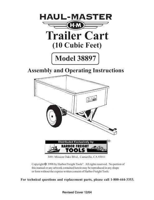
Trailer Cart<br />
(10 Cubic Feet)<br />
Model <strong>38897</strong><br />
Assembly and Operating Instructions<br />
®<br />
3491 Mission Oaks Blvd., Camarillo, CA 93011<br />
Copyright 1998 by <strong>Harbor</strong> <strong>Freight</strong> <strong>Tools</strong> ® . All rights reserved. No portion of<br />
this <strong>manual</strong> or any artwork contained herein may be reproduced in any shape<br />
or form without the express written consent of <strong>Harbor</strong> <strong>Freight</strong> <strong>Tools</strong>.<br />
For technical questions and replacement parts, please call 1-800-444-3353.<br />
Revised Cover 12/04
Thank you for choosing a <strong>Harbor</strong> <strong>Freight</strong> <strong>Tools</strong> product! For future reference, please complete the owner’s<br />
record below:<br />
Model:___________________<br />
Purchase Date:_________________<br />
Save the receipt, warranty card and these instructions. It is important that you read the entire instruction sheet<br />
to become familiar with this product before you begin using it.<br />
Technical Specifications:<br />
This heavy duty Trailer Cart has a large 10 cubic foot bed capacity. It has a tail gate<br />
which is easy to lift out, and the the bed tilts with a quick release feature.<br />
Cart Dimensions: 43” x 33” x 12”; Inside Bed Dimensions: 41” x 30” x 12”<br />
16” Wheels with Pneumatic Tires; Pin Hitch: #5/8” Pin Hole<br />
Trailer Cart Capacity: 600 Lbs.<br />
Warning:<br />
1. Always wear ANSI approved safety goggles when assembling this product and when<br />
working with tools and equipment.<br />
2. The Trailer Cart has a safe working capacity of 600 lbs. Never exceed this<br />
weight capacity.<br />
3. When unloading and loading the <strong>cart</strong>, be careful of the balance of the <strong>cart</strong>. Always<br />
engage the tongue latch to the towing vehicle before loading the Trailer Cart. The <strong>cart</strong> will<br />
ride best with the load centered over and in front of the axle.<br />
4. Never allow children to play in or operate the <strong>cart</strong>. This <strong>cart</strong> is not designed for carrying<br />
people or animals.<br />
5. This Trailer Cart is not designed for use on public highways. Always use low speeds<br />
(under 5 MPH) when performing off road hauling.<br />
6. Before each use, check the tongue latch connection to the towing vehicle to insure safe<br />
operation. Before each use, check the condition of pneumatic tires (recommended tire<br />
pressure is 30 PSI).<br />
#<strong>38897</strong> Page 2
Assembly of the Trailer Cart<br />
The Trailer Cart requires a good deal of assembly, but with the right tools and careful reading of this <strong>manual</strong>,<br />
assembly should be fairly routine. You will need a regular screwdriver, pair of pliers, two 14 mm. open end<br />
wrenches and two 13 mm. open or box end wrenches (similar size ratchet wrenches will speed assembly).<br />
Part numbers shown below refer to the Part Number Listing on page 9.<br />
It is recommended that all the parts be put<br />
out on a flat surface before beginning to<br />
assemble the Trailer Cart. Check to see that<br />
all parts shown in this <strong>manual</strong> are present<br />
(refer to parts illustrations and the part number<br />
listing on page 9). If any parts are missing<br />
or in damaged condition, please call <strong>Harbor</strong><br />
<strong>Freight</strong> <strong>Tools</strong> at the telephone number shown<br />
on the cover of this <strong>manual</strong>.<br />
Hardware<br />
Required hardware needed to assemble<br />
the Trailer Cart is shown below:<br />
Step 1: Lay out the two Bottom Panels (#1)<br />
as shown in Figure 1 below. Attach the Front<br />
Cross Brace (#2) to the Bottom Panels using<br />
4 Bolts (#21), 4 Washers (#23) and 4 Nuts<br />
(#24).<br />
Bottom Panels<br />
(#1)<br />
Front Cross<br />
Brace (#2)<br />
Figure 1<br />
Step 2: Connect the two Bottom Panels shown in Figure 2 using 4 Bolts (#21), 4 Washers (#23) and 4 Nuts<br />
(#24).<br />
#<strong>38897</strong> Page 3
Bottom Panels<br />
(#1)<br />
Bolt Locations<br />
Figure 2<br />
Step 3: Attach the Tongue Support (#3) to the Bottom<br />
Panels using 2 Bolts (#22), 2 Washers (#23), and 2 Nuts<br />
(#24) - see Figure 3.<br />
Tongue Support<br />
(#3)<br />
Figure 3<br />
Step 4: As shown in Figure 4 below, bolt the 2 Wheel Axle Supports together using 8 Bolts (#25), 8 Washers<br />
(#23) and 8 Nuts (#24). Note: Only hand tighten these 8 Bolts (#25) now, Bolts should be securely tightened<br />
once Wheel Axle is installed (see Step 6, page 5).<br />
Wheel Axle Supports<br />
(#4)<br />
#<strong>38897</strong><br />
Figure 4<br />
Page 4<br />
REV 02/07
Step 5: Bolt the Wheel Axle Supports (#4) to the<br />
Bottom Panels (#1) using 8 Bolts (#21), 8 Washers<br />
(#23), and 8 Nuts (#24) - see Figure 5<br />
Hitch Tongue (#10)<br />
Wheel Axle (#5)<br />
Figure 5<br />
Figure 6<br />
Wheel/Tire<br />
Assembly (#6)<br />
Step 6: As shown in Figure 6, put the Hitch Tongue in place and insert the Wheel Axle (#5) throught the Wheel<br />
Axle Support (#4). Install the 2 Wheel/Tire Assemblies (#6) with Washers (#26) and Cotter Pins (#27).<br />
Step 7: As shown in Figure 7, insert the Tongue Latch (#9)<br />
up through the opening in the Hitch Tongue (#10). Using<br />
a Latch Spacer (#8) on each side of the Tongue Latch, bolt<br />
the Latch Spacer to the Hitch Tongue using Bolt (#29) and<br />
Nut (#30). Only hand tighten this bolt for now.<br />
Latch Spring (#7)<br />
Attach one end of the Latch Spring (#7) to the<br />
opening in the Hitch Tongue (#10) and the other end<br />
to the top hole in the Latch Spacer (#8). With the<br />
Latch Spring in place, tighten the bolt described<br />
in the above paragraph.<br />
Latch Spacer (#8)<br />
Hitch Tongue (#10)<br />
Tongue Latch (#9)<br />
Figure 7<br />
#<strong>38897</strong> Page 5<br />
REV 02/07
Hitch Tongue (#10)<br />
Step 8: As shown in Figure 8, install the Hitch Pin Bracket<br />
(#11) by using 2 Bolts (#25), 2 Washers (#23), and 2 Nuts<br />
(#24) in the rear most two holes. The Hitch Pin (#28) fits in<br />
the front hole, and is secured in place with a Cotter Pin (#27).<br />
Hitch Pin Bracket (#11)<br />
Rear Cross Brace (#12)<br />
Figure 8<br />
Rear Corner Brackers (#13)<br />
Bottom Panels<br />
Figure 9<br />
Step 9: Turn the Trailer Cart over onto it’s wheels. To the rear portion of the Bottom Panels (#1), attach the<br />
Rear Corner Brackets (#13) and the Rear Cross Brace (#12), by using 4 Bolts (#21), 4 Washers (#23) and 4<br />
Nuts (#24).<br />
Side Panel (#14)<br />
Step 10: As seen in Figure 10, assemble the<br />
left Side Panel (#14) using 2 Bolts (#21),<br />
2 Washers (#23) and 2 Nuts (#24). Insert<br />
bolts in the holes shown. See Step 13,<br />
page 7 for instructions on installing 2 other<br />
bolts into Side Panel.<br />
Figure 10<br />
#<strong>38897</strong> Page 6<br />
REV 02/07
Rear Cross Brace (#12)<br />
Step 11: See Figure 11 for bolt positions. Bolt Rear<br />
Cross Brace (#12) to Bottom Panels (#1) using 6 Bolts<br />
(#21), 6 Washers (#23) and 6 Nuts (#24).<br />
Bottom Panel (#1)<br />
Figure 11<br />
Step 12: Install the right Side Panel (#14)<br />
to the Bottom Panel (#1) as shown in Figure<br />
12. Use 2 Bolts (#21), 2 Washers (#23), and<br />
2 Nuts (#24) to attach the Side Panel.<br />
See Step 13 below for instructions on<br />
installing 2 other bolts into side panel.<br />
Bolt Locations<br />
Step 13: Secure each Side Panel (#14) by<br />
bolting a Rear Corner Brace (#15) to the<br />
outside of the Side Panel. Use 5 Bolts (#21),<br />
5 Washers (#23) and 5 Nuts (#24) to secure<br />
each Side Panel. Figure 13 shows Rear<br />
Corner Brace being assembled to<br />
left Side Panel. Follow same<br />
procedure to assemble Rear Corner<br />
Brace to right Side Panel.<br />
Figure 12<br />
Rear Corner Brace (#15)<br />
#<strong>38897</strong><br />
Figure 13<br />
Page 7<br />
REV 02/07
Step 14: Assemble the Front Panel (#16)<br />
to the Front Cross Brace (#2) and the two<br />
Side Panels (#14) by using 12 Bolts (#21),<br />
12 Washers (#23) and 12 Nuts (#24). Bolt<br />
positions are shown in Figure 14 at right.<br />
Front Corner Brace (#17)<br />
Figure 14<br />
Step 15: Assemble the two Front Corner Braces<br />
(#17) to the corners of the Front Panel and the<br />
Side Panels (see Figure 15). For each Front Corner<br />
Brace use 2 Bolts (#21), 2 Washers (#23) and 2<br />
Nuts (#24).<br />
Figure 15<br />
Tailgate (#20)<br />
(view of inside)<br />
Step 16: Attach the two Tailgate<br />
Latches (#18) to the inside of the<br />
Tailgate (#20) using 2 Bolts (#21),<br />
2 Washers (#23) and 2 Nuts (#24)<br />
for each Tailgate Latch (see Figure 16).<br />
Insert the two Tailgate Pins (#19) through<br />
the two holes in lower portion of the Tailgate,<br />
and secure the Tailgate Pins by adding a Washer<br />
(#32) and a Nut (#31) to the threaded portion.<br />
Tailgate Latch (#18)<br />
The Tailgate is now ready to be put in place on the Trailer<br />
Figure 16<br />
Cart. Position the Tailgate so that the two Tailgate Pins can be<br />
dropped into the two holes on the Rear Cross Brace (#12). The<br />
Tailgate Latches can now be dropped over the open slots in each Side Panel which will lock the Tailgate in<br />
place. Assembly of the Trailer Cart is complete. Before using the <strong>cart</strong> make sure all hardware connections are<br />
tight.<br />
#<strong>38897</strong> Page 8
Part Number Listing<br />
Part # Reference # Description Qty<br />
1 234A1 Bottom Panel 2<br />
2 234A2 Front Cross Brace 1<br />
3 234A3 Tongue Support 1<br />
4 234A4 Wheel Axle Support 2<br />
5 234A5 Wheel Axle 1<br />
6 234A6 Wheel/Tire Assembly 2<br />
7 234A7 Latch Spring 1<br />
8 234A8 Latch Spacer 2<br />
9 234A9 Tongue Latch 1<br />
10 234A10 Hitch Tongue 1<br />
11 234A11 Hitch Pin Bracket 1<br />
12 234A12 Rear Cross Brace 1<br />
13 234A13 Rear Corner Bracket 2<br />
14 234A14 Side Panel 2<br />
15 234A15 Rear Corner Brace 2<br />
16 234A16 Front Panel 1<br />
17 234A17 Front Corner Brace 2<br />
18 234A18 Tailgate Latch 2<br />
19 234A19 Tailgate Pin 2<br />
20 234A20 Tailgate 1<br />
Hardware<br />
21 234B1 M8x16 Truss Head Bolt 60<br />
22 234B2 M8x20 Truss Head Bolt 2<br />
23 234B3 8mm Lock Washer 72<br />
24 234B4 8mm Hex Nut 72<br />
25 234B5 M8x20 Hex Head Bolt 10<br />
26 234B6 20mm Flat Washer 2<br />
27 234B7 3mm Cotter Pin 3<br />
28 234B8 12.5x 64 Hitch Pin 1<br />
29 234B9 M6x90 Hex Head Bolt 1<br />
30 234B10 6mm Nylon Nut 1<br />
31 234B11 6mm Hex Nut 2<br />
32 234B12 6-8mm Flat Washer 2<br />
#<strong>38897</strong> Page 9