68049 Parts List and Assembly Diagram - Harbor Freight Tools
68049 Parts List and Assembly Diagram - Harbor Freight Tools
68049 Parts List and Assembly Diagram - Harbor Freight Tools

Create successful ePaper yourself
Turn your PDF publications into a flip-book with our unique Google optimized e-Paper software.
Table of Contents<br />
Safety.......................................................... 2<br />
Setup........................................................... 3<br />
Operation..................................................... 4<br />
Maintenance................................................ 6<br />
<strong>Parts</strong> <strong>List</strong>s <strong>and</strong> <strong>Assembly</strong> <strong>Diagram</strong>s............ 8<br />
Warranty..................................................... 11<br />
SAFETY SETUP<br />
OPERATION MAINTENANCE<br />
WARNING SYMBOLS AND DEFINITIONS<br />
This is the safety alert symbol. It is used to alert you to potential personal injury hazards.<br />
Obey all safety messages that follow this symbol to avoid possible injury or death.<br />
Indicates a hazardous situation which, if not avoided,<br />
will result in death or serious injury.<br />
Indicates a hazardous situation which, if not avoided,<br />
could result in death or serious injury.<br />
Indicates a hazardous situation which, if not avoided,<br />
could result in minor or moderate injury.<br />
Addresses practices not related to personal injury.<br />
IMPORTANT SAFETY INFORMATION<br />
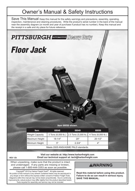
Floor Jack Safety Warnings<br />
1. Study, underst<strong>and</strong>, <strong>and</strong> follow all instructions<br />
before operating this device.<br />
2. Do not exceed rated capacity.<br />
3. Use only on hard, level surfaces.<br />
4. Lifting device only. Immediately after lifting,<br />
support the vehicle with appropriate means.<br />
5. Do not move or dolly the vehicle while on the jack.<br />
6. Failure to heed these markings may result in<br />
personal injury <strong>and</strong>/or property damage.<br />
7. Lift only areas of the vehicle as specified<br />
by the vehicle manufacturer.<br />
8. No alterations shall be made to this product.<br />
9. Never work on, under or around a load<br />
supported only by this device.<br />
10. Do not adjust safety valve.<br />
11. Wear ANSI-approved safety goggles <strong>and</strong><br />
heavy-duty work gloves during use.<br />
12. Keep clear of load while lifting <strong>and</strong> lowering.<br />
13. Lower load slowly.<br />
14. Apply parking brake <strong>and</strong> chock<br />
tires before lifting vehicle.<br />
15. Lift vehicle only at manufacturer<br />
recommended locations.<br />
16. Inspect before every use; do not use<br />
if parts are loose or damaged.<br />
17. Do not use for aircraft purposes.<br />
18. The warnings, precautions, <strong>and</strong> instructions<br />
discussed in this manual cannot cover all<br />
possible conditions <strong>and</strong> situations that may occur.<br />
The operator must underst<strong>and</strong> that common sense<br />
<strong>and</strong> caution are factors, which cannot be built into<br />
this product, but must be supplied by the operator.<br />
19. The brass components of this product contain lead,<br />
a chemical known to the State of California to cause<br />
cancer, birth defects (or other reproductive harm).<br />
(California Health & Safety code § 25249.5, et seq.)<br />
IMPORTANT! Before first use:<br />
Check hydraulic oil level <strong>and</strong> fill to 1/4″ below<br />
the fill port as needed as stated on page 4.<br />
Thoroughly test the Jack for proper operation.<br />
If it does not work properly, bleed air from its<br />
hydraulic system as stated on page 4.<br />
SAVE THESE INSTRUCTIONS.<br />
Page 2 For technical questions, please call 1-800-444-3353. Floor Jack
Setup - Before Use:<br />
Read the ENTIRE IMPORTANT SAFETY INFORMATION section at the beginning of this<br />
manual including all text under subheadings therein before set up or use of this product.<br />
Note: For additional information regarding the parts listed in the following pages,<br />
refer to <strong>Parts</strong> <strong>List</strong>s <strong>and</strong> <strong>Assembly</strong> <strong>Diagram</strong>s on page 8.<br />
Functions<br />
SAFETY<br />
H<strong>and</strong>le<br />
Saddle<br />
Oil Fill Screw<br />
(Not Shown)<br />
Lifting Arm<br />
Rear Caster<br />
H<strong>and</strong>le Socket<br />
U-Joint (Not Shown)<br />
Figure A<br />
Safety Valve<br />
Cover<br />
DO NOT OPEN<br />
OR ADJUST<br />
Fill Screw<br />
U-Joint<br />
Hydraulic Unit<br />
MAINTENANCE OPERATION<br />
SETUP<br />
Floor Jack<br />
For technical questions, please call 1-800-444-3353.<br />
Page 3
Operating Instructions<br />
Read the ENTIRE IMPORTANT SAFETY INFORMATION section at the beginning of this<br />
manual including all text under subheadings therein before set up or use of this product.<br />
SAFETY SETUP<br />
OPERATION MAINTENANCE<br />
Tool Set Up<br />
Attaching the H<strong>and</strong>le<br />
1. Fasten the Upper H<strong>and</strong>le to the Lower H<strong>and</strong>le.<br />
2. Loosen the Set Screw <strong>and</strong> insert the<br />
assembled H<strong>and</strong>le into the H<strong>and</strong>le Socket.<br />
Bleeding<br />
1. Loosen the Fill Screw.<br />
2. Insert the H<strong>and</strong>le into the H<strong>and</strong>le Socket<br />
to operate the Release Valve.<br />
3. Turn the H<strong>and</strong>le counterclockwise to open the valve.<br />
Adding Oil<br />
1. Remove the Fill Screw.<br />
2. Add high grade hydraulic fluid into the Fill Screw<br />
slowly until the oil reaches the top of the oil fill hole.<br />
3. Tighten the Set Screw.<br />
4. Pump the H<strong>and</strong>le up <strong>and</strong> down quickly several<br />
times to purge air from the system.<br />
5. Tighten the Fill Screw.<br />
Note: Do not touch the H<strong>and</strong>le when<br />
adding the hydraulic oil.<br />
3. Replace the Fill Screw.<br />
Page 4 For technical questions, please call 1-800-444-3353. Floor Jack
General Operating Instructions<br />
Lifting<br />
Park vehicle on a flat, level, solid, surface safely away from oncoming traffic. Turn off the vehicle’s<br />
engine. Place the vehicle’s transmission in “PARK” (if automatic) or in its lowest gear (if manual).<br />
Set the vehicle’s emergency brake. Then, chock the wheels that are not being lifted.<br />
1. Turn the H<strong>and</strong>le counterclockwise to lower the Jack.<br />
Once the Jack is fully lowered, turn the<br />
H<strong>and</strong>le firmly clockwise to close it.<br />
2. Carefully position the Saddle of the Jack under<br />
the vehicle manufacturer’s recommended lifting<br />
point. (See vehicle manufacturer’s owner’s<br />
manual for location of frame lifting point.)<br />
3. Pump the H<strong>and</strong>le until the top of the Jack’s Saddle<br />
has nearly reached the vehicle lifting point. Position<br />
the Saddle directly under the vehicle’s lifting point.<br />
4. To lift the vehicle, pump the H<strong>and</strong>le of<br />
the Jack. Use smooth, full strokes.<br />
5. Once the vehicle is raised, slide a jack st<strong>and</strong> of<br />
appropriate capacity (not included) under a proper<br />
lifting point referred to in the vehicle owner’s<br />
manual. Always use two jack st<strong>and</strong>s, position them<br />
at the same point on each side of the vehicle.<br />
Lowering<br />
1. Carefully remove all tools, parts, etc.<br />
from under the vehicle.<br />
2. Position the Saddle under the lifting point.<br />
Turn the H<strong>and</strong>le firmly clockwise <strong>and</strong> raise<br />
load high enough to clear the jack st<strong>and</strong>s,<br />
then carefully remove jack st<strong>and</strong>s.<br />
3. Slowly turn the H<strong>and</strong>le counterclockwise<br />
(never more than 1/2 full turn) to lower<br />
the vehicle onto the ground.<br />
WARNING! The rated capacity of jack st<strong>and</strong>s is per<br />
pair, not the individual capacities combined unless<br />
specifically noted on the product by the jack st<strong>and</strong><br />
manufacturer. Do not exceed rated jack st<strong>and</strong> capacity.<br />
Ensure that the vehicle support points are fully seated<br />
in the saddle of both jack st<strong>and</strong>s. Use a matched pair<br />
of jack st<strong>and</strong>s per vehicle to support one end only.<br />
Failure to do so may result in the load suddenly falling,<br />
which may cause personal injury <strong>and</strong>/or property damage.<br />
6. Center the vehicle’s lifting point(s) on the saddle of<br />
the jack st<strong>and</strong>(s). Set the jack st<strong>and</strong>(s) to the same<br />
height according to the manufacturer’s instructions,<br />
making sure that they lock securely into position.<br />
7. Slowly turn the H<strong>and</strong>le counterclockwise to lower<br />
the vehicle onto the saddle(s) of the jack st<strong>and</strong>(s).<br />
Then, turn the H<strong>and</strong>le firmly clockwise to close it.<br />
4. Lower the Jack completely. Then, store in a<br />
safe, dry location out of reach of children.<br />
5. To prevent accidents, turn off the tool <strong>and</strong><br />
disconnect its power supply after use. Clean, then<br />
store the tool indoors out of children’s reach.<br />
SAFETY<br />
MAINTENANCE OPERATION<br />
SETUP<br />
Floor Jack<br />
For technical questions, please call 1-800-444-3353.<br />
Page 5
Maintenance <strong>and</strong> Servicing<br />
Procedures not specifically explained in this manual must<br />
be performed only by a qualified technician.<br />
SAFETY SETUP<br />
OPERATION MAINTENANCE<br />
TO PREVENT SERIOUS INJURY FROM TOOL FAILURE:<br />
Do not use damaged equipment. If abnormal noise or vibration<br />
occurs, have the problem corrected before further use.<br />
Cleaning, Maintenance, <strong>and</strong> Lubrication<br />
1. Before each use, inspect the general condition<br />
of the Jack. Check for broken, cracked, or bent<br />
parts, loose or missing parts, <strong>and</strong> any condition<br />
that may affect the proper operation of the product.<br />
If a problem occurs, have the problem corrected<br />
before further use.<br />
Do not use damaged equipment.<br />
2. Before each use, thoroughly test the Jack<br />
for proper operation prior to its actual use.<br />
If the Jack appears not to be working properly,<br />
follow Bleeding instructions on page 4.<br />
3. Change the hydraulic oil at least<br />
once every three years:<br />
A. With the Jack fully lowered, remove the Oil<br />
Filler Plug on the side of the Housing.<br />
B. Tip the Jack to allow the old hydraulic oil<br />
to drain out of the Housing completely,<br />
<strong>and</strong> dispose of the old hydraulic oil in<br />
accordance with local regulations.<br />
C. With the Jack upright, completely fill the<br />
Housing with a high quality hydraulic oil (not<br />
included) until the oil is 1/4″ below the fill hole.<br />
D. Open the valve by turning the H<strong>and</strong>le<br />
counterclockwise <strong>and</strong> pump the H<strong>and</strong>le<br />
to bleed air from the system.<br />
E. Recheck oil level <strong>and</strong> re-fill as needed.<br />
F. Reinstall the Oil Filler Plug.<br />
7. Wipe dry with a clean cloth. Then, store the<br />
Jack in a safe, dry location out of reach of<br />
children <strong>and</strong> other non-authorized people.<br />
Page 6 For technical questions, please call 1-800-444-3353. Floor Jack
Troubleshooting<br />
TO PREVENT SERIOUS INJURY:<br />
Use caution when troubleshooting a malfunctioning jack. Stay well clear of the supported load.<br />
Completely resolve all problems before use. If the solutions presented in the Troubleshooting guide<br />
do not solve the problem, have a qualified technician inspect <strong>and</strong> repair the jack before use.<br />
After the jack is repaired: Test it carefully without a load by raising <strong>and</strong> lowering it fully,<br />
checking for proper operation, BEFORE RETURNING THE JACK TO OPERATION.<br />
DO NOT USE A DAMAGED OR MALFUNCTIONING JACK!<br />
SAFETY<br />
POSSIBLE SYMPTOMS<br />
Jack will<br />
not lift at<br />
its weight<br />
capacity<br />
X<br />
Saddle<br />
lowers<br />
under<br />
load<br />
X<br />
Pump<br />
stroke<br />
feels<br />
spongy<br />
Saddle<br />
will not<br />
lift all<br />
the way<br />
H<strong>and</strong>le<br />
moves up<br />
when jack<br />
is under<br />
load<br />
Oil leaking<br />
from filler<br />
plug<br />
PROBABLE SOLUTION<br />
(Make certain that the jack is not supporting a load while attempting a solution.)<br />
Check that Release Valve is fully closed.<br />
Bleed air from the system.<br />
X X X<br />
X X X<br />
X<br />
Valves may be blocked <strong>and</strong> may not close fully. To flush the valves:<br />
1. Lower the Saddle <strong>and</strong> securely close the Release Valve.<br />
2. Manually lift the saddle several inches.<br />
3. Open the release valve <strong>and</strong> force the saddle down as quickly as possible.<br />
Jack may be low on oil. Check the oil level <strong>and</strong> refill if needed.<br />
Jack may require bleeding - see instructions on page Bleeding on page 4.<br />
Unit may have too much hydraulic oil inside, check fluid level <strong>and</strong> adjust if needed.<br />
MAINTENANCE OPERATION<br />
SETUP<br />
Floor Jack<br />
For technical questions, please call 1-800-444-3353.<br />
Page 7
<strong>Parts</strong> <strong>List</strong>s <strong>and</strong> <strong>Assembly</strong> <strong>Diagram</strong>s<br />
68048 <strong>Parts</strong> <strong>List</strong> <strong>and</strong> <strong>Assembly</strong> <strong>Diagram</strong><br />
SAFETY SETUP<br />
OPERATION MAINTENANCE<br />
Part Description Qty<br />
1 Retaining Ring (M20) 2<br />
2 Washer 2<br />
3 Front Wheel 2<br />
4 Frame 1<br />
5 Retaining Ring (M16) 2<br />
6 Bolt 2<br />
7 Retaining Ring (M22) 2<br />
8 Hydraulic Adaptor 1<br />
9 Lift Arm <strong>Assembly</strong> 1<br />
10 Saddle 1<br />
11 Saddle Screw 1<br />
12 Retaining Ring (M25) 2<br />
13 Lift Arm Shaft 1<br />
14 Pin (M4x45) 1<br />
15 Spring 2<br />
16 Hydraulic Unit 1<br />
17 Bolt 2<br />
18 Washer (M18) 2<br />
19 Set Screw 1<br />
Part Description Qty<br />
20 Retaining Ring (M12) 1<br />
21 H<strong>and</strong>le Socket Roller 1<br />
22 Shaft 1<br />
23 H<strong>and</strong>le Socket 1<br />
24 Rubber Bumper 2<br />
25 Screw 1<br />
26 Lower H<strong>and</strong>le 1<br />
27 Upper H<strong>and</strong>le 1<br />
28 Nut (M16) 4<br />
29 Washer (M16) 4<br />
30 Tie Rod 2<br />
31 Washer (M8) 4<br />
32 Screw (M8X20) 4<br />
33 Screw (M10X25) 4<br />
34 Washer (M10) 4<br />
35 Rear Caster <strong>Assembly</strong> 2<br />
36 Cover Plate 1<br />
37 Screw 4<br />
Page 8 For technical questions, please call 1-800-444-3353. Floor Jack
<strong>68049</strong> <strong>Parts</strong> <strong>List</strong> <strong>and</strong> <strong>Assembly</strong> <strong>Diagram</strong><br />
Part Description Qty<br />
1 Retaining Ring (M20) 2<br />
2 Washer (M20) 2<br />
3 Front Wheel 2<br />
4 Frame 1<br />
5 Nut (M16) 4<br />
6 Washer (M16) 4<br />
7 Screw (M5X12) 4<br />
8 Rear Caster <strong>Assembly</strong> 2<br />
9 Screw (M10X20) 4<br />
10 Washer (M10) 4<br />
11 Bolt 2<br />
12 Washer (M18) 2<br />
13 Retaining Ring (M12) 1<br />
14 H<strong>and</strong>le Socket Roller 1<br />
15 H<strong>and</strong>le Socket 1<br />
16 Shaft 1<br />
Part Description Qty<br />
17 Set Screw 1<br />
18 Upper H<strong>and</strong>le 1<br />
19 Lower H<strong>and</strong>le 1<br />
20 Screw (M6X35) 1<br />
21 U-Joint 1<br />
22 Hydraulic Unit 1<br />
23 Spring 2<br />
24 Retaining Ring (M22) 2<br />
25 Hydraulic Unit Adaptor 1<br />
26 Pin (A4x55) 1<br />
27 Retaining Ring (M25) 2<br />
28 Lift Arm Shaft 1<br />
29 Cover Plate 1<br />
30 Saddle 1<br />
31 Saddle Screw 1<br />
32 H<strong>and</strong>le Bumper 1<br />
SAFETY<br />
MAINTENANCE OPERATION<br />
SETUP<br />
32<br />
Floor Jack<br />
For technical questions, please call 1-800-444-3353.<br />
Page 9
68056 <strong>Parts</strong> <strong>List</strong> <strong>and</strong> <strong>Assembly</strong> <strong>Diagram</strong><br />
SAFETY SETUP<br />
OPERATION MAINTENANCE<br />
Part Description Qty<br />
1 Retaining Ring (M20) 2<br />
2 Front Wheel Washer 2<br />
3 Front Wheel 2<br />
4 Frame 1<br />
5 Rear Caster 2<br />
6 Screw (M12X25) 4<br />
7 Washer (M12) 4<br />
8 Washer (M16) 4<br />
9 Retaining Ring (M30) 2<br />
10 Screw (M5X12) 4<br />
11 Screw (M8X20) 4<br />
12 Washer (M8) 4<br />
13 Tie Rod 2<br />
14 Bolt 2<br />
15 Washer (M18) 2<br />
16 Nut (M16) 4<br />
17 Rubber Bumper 2<br />
18 Upper H<strong>and</strong>le 1<br />
19 Screw 1<br />
Part Description Qty<br />
20 Lower H<strong>and</strong>le 1<br />
21 Set Screw 1<br />
22 H<strong>and</strong>le Socket 1<br />
23 Hydraulic Unit 1<br />
24 U-Joint 1<br />
25 Spring 2<br />
26 Cover Plate 1<br />
27 Retaining Ring (M25) 2<br />
28 Pin (M4X45) 1<br />
29 Hydraulic Unit Adaptor 1<br />
30 Lift Arm Shaft 1<br />
31 Bolt 2<br />
32 Retaining Ring (M18) 2<br />
33 Radius Link 2<br />
34 Zerk 1<br />
35 Lift Arm 1<br />
36 Saddle 1<br />
37 Saddle Screw 1<br />
38 H<strong>and</strong>le Bumper 1<br />
Page 10 For technical questions, please call 1-800-444-3353. Floor Jack
Record Product’s Serial Number Here:<br />
Note: If product has no serial number, record month <strong>and</strong> year of purchase instead.<br />
Note: Some parts are listed <strong>and</strong> shown for illustration purposes only,<br />
<strong>and</strong> are not available individually as replacement parts.<br />
PLEASE READ THE FOLLOWING CAREFULLY<br />
THE MANUFACTURER AND/OR DISTRIBUTOR HAS PROVIDED THE PARTS LIST AND ASSEMBLY DIAGRAM<br />
IN THIS MANUAL AS A REFERENCE TOOL ONLY. NEITHER THE MANUFACTURER OR DISTRIBUTOR<br />
MAKES ANY REPRESENTATION OR WARRANTY OF ANY KIND TO THE BUYER THAT HE OR SHE IS<br />
QUALIFIED TO MAKE ANY REPAIRS TO THE PRODUCT, OR THAT HE OR SHE IS QUALIFIED TO REPLACE<br />
ANY PARTS OF THE PRODUCT. IN FACT, THE MANUFACTURER AND/OR DISTRIBUTOR EXPRESSLY<br />
STATES THAT ALL REPAIRS AND PARTS REPLACEMENTS SHOULD BE UNDERTAKEN BY CERTIFIED AND<br />
LICENSED TECHNICIANS, AND NOT BY THE BUYER. THE BUYER ASSUMES ALL RISK AND LIABILITY<br />
ARISING OUT OF HIS OR HER REPAIRS TO THE ORIGINAL PRODUCT OR REPLACEMENT PARTS<br />
THERETO, OR ARISING OUT OF HIS OR HER INSTALLATION OF REPLACEMENT PARTS THERETO.<br />
SAFETY<br />
Limited 90 Day Warranty<br />
<strong>Harbor</strong> <strong>Freight</strong> <strong>Tools</strong> Co. makes every effort to assure that its products meet high quality <strong>and</strong> durability st<strong>and</strong>ards,<br />
<strong>and</strong> warrants to the original purchaser that this product is free from defects in materials <strong>and</strong> workmanship for the<br />
period of 90 days from the date of purchase. This warranty does not apply to damage due directly or indirectly,<br />
to misuse, abuse, negligence or accidents, repairs or alterations outside our facilities, criminal activity, improper<br />
installation, normal wear <strong>and</strong> tear, or to lack of maintenance. We shall in no event be liable for death, injuries<br />
to persons or property, or for incidental, contingent, special or consequential damages arising from the use of<br />
our product. Some states do not allow the exclusion or limitation of incidental or consequential damages, so the<br />
above limitation of exclusion may not apply to you. THIS WARRANTY IS EXPRESSLY IN LIEU OF ALL OTHER<br />
WARRANTIES, EXPRESS OR IMPLIED, INCLUDING THE WARRANTIES OF MERCHANTABILITY AND FITNESS.<br />
To take advantage of this warranty, the product or part must be returned to us with transportation charges<br />
prepaid. Proof of purchase date <strong>and</strong> an explanation of the complaint must accompany the merch<strong>and</strong>ise.<br />
If our inspection verifies the defect, we will either repair or replace the product at our election or we may<br />
elect to refund the purchase price if we cannot readily <strong>and</strong> quickly provide you with a replacement. We will<br />
return repaired products at our expense, but if we determine there is no defect, or that the defect resulted<br />
from causes not within the scope of our warranty, then you must bear the cost of returning the product.<br />
This warranty gives you specific legal rights <strong>and</strong> you may also have other rights which vary from state to state.<br />
MAINTENANCE OPERATION<br />
SETUP<br />
Floor Jack<br />
For technical questions, please call 1-800-444-3353.<br />
Page 11
3491 Mission Oaks Blvd. • PO Box 6009 • Camarillo, CA 93011 • (800) 444-3353