MOTORCYCLE LIFT - Harbor Freight Tools
MOTORCYCLE LIFT - Harbor Freight Tools
MOTORCYCLE LIFT - Harbor Freight Tools

You also want an ePaper? Increase the reach of your titles
YUMPU automatically turns print PDFs into web optimized ePapers that Google loves.
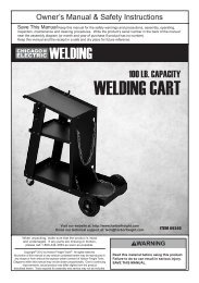
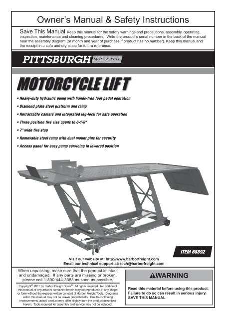
Owner’s Manual & Safety Instructions<br />
Save This Manual Keep this manual for the safety warnings and precautions, assembly, operating,<br />
inspection, maintenance and cleaning procedures. Write the product’s serial number in the back of the manual<br />
near the assembly diagram (or month and year of purchase if product has no number). Keep this manual and<br />
the receipt in a safe and dry place for future reference.<br />
<strong>MOTORCYCLE</strong> LIF T<br />
ITEM 91746<br />
• Heavy-duty hydraulic pump with hands-free foot pedal operation<br />
• Diamond plate steel platform and ramp<br />
• Retractable casters and integrated leg-lock for safe operation<br />
• Three position tire vise opens to 6-1/8"<br />
• 7" wide tire stop<br />
• Removable steel ramp with dual mount pins for security<br />
• Access panel for easy pump servicing in lowered position<br />
Visit our website at: http://www.harborfreight.com<br />
Email our technical support at: tech@harborfreight.com<br />
When unpacking, make sure that the product is intact<br />
and undamaged. If any parts are missing or broken,<br />
please call 1-800-444-3353 as soon as possible.<br />
Copyright © 2011 by <strong>Harbor</strong> <strong>Freight</strong> <strong>Tools</strong> ® . All rights reserved. No portion of<br />
this manual or any artwork contained herein may be reproduced in any shape<br />
or form without the express written consent of <strong>Harbor</strong> <strong>Freight</strong> <strong>Tools</strong>. Diagrams<br />
within this manual may not be drawn proportionally. Due to continuing<br />
improvements, actual product may differ slightly from the product described<br />
herein. <strong>Tools</strong> required for assembly and service may not be included.<br />
ITEM 68892<br />
Read this material before using this product.<br />
Failure to do so can result in serious injury.<br />
Save this manual.
Table of Contents<br />
Important Safety Instructions...................... 2<br />
Specifications.............................................. 3<br />
Assembly Instructions................................. 3<br />
Operating Instructions................................. 5<br />
Maintenance and Servicing................................ 7<br />
Parts List............................................................ 8,10<br />
Assembly Diagram............................................. 9,10<br />
Warranty............................................................. 11<br />
WARNING SYMBOLS AND DEFINITIONS<br />
This is the safety alert symbol. It is used to alert you to potential personal injury hazards.<br />
Obey all safety messages that follow this symbol to avoid possible injury or death.<br />
Indicates a hazardous situation which, if not avoided,<br />
will result in death or serious injury.<br />
Indicates a hazardous situation which, if not avoided,<br />
could result in death or serious injury.<br />
Indicates a hazardous situation which, if not avoided,<br />
could result in minor or moderate injury.<br />
Addresses practices not related to personal injury.<br />
IMPORTANT SAFETY INSTRUCTIONS<br />
Failure to heed these Instructions<br />
may result in personal injury<br />
and/or property damage.<br />
Read All Instructions<br />
1. Study, understand, and follow all instructions<br />
before operating this device.<br />
2. Do not exceed rated capacity. Be aware<br />
of dynamic loading! Bouncing or dropping<br />
the load suddenly may briefly create<br />
excess load causing product failure.<br />
3. Use only on hard, level surfaces.<br />
4. Center load on lift platform.<br />
5. Immediately after lifting load, ensure<br />
that the Locking Bar is in place.<br />
6. Before moving, lower the load to<br />
the lowest possible point.<br />
7. Secure load with appropriate restraint device.<br />
8. Do not adjust safety valve.<br />
9. Wear ANSI-approved safety goggles, heavy‐duty<br />
work gloves and safety shoes during use.<br />
10. Keep clear of load while lifting,<br />
moving and lowering.<br />
11. Lower load slowly.<br />
12. Do not use for aircraft purposes.<br />
13. Inspect before every use; do not use<br />
if parts are loose or damaged.<br />
14. Keep work area clean and well lit.<br />
Cluttered or dark areas invite accidents.<br />
15. Keep children and bystanders away<br />
while operating. Distractions can<br />
cause you to lose control.<br />
16. Stay alert. Watch what you are doing, and use<br />
common sense when operating. Do not use while<br />
tired or under the influence of drugs, alcohol,<br />
or medication. A moment of inattention while<br />
operating may result in serious personal injury.<br />
17. Store idle lifts out of the reach of children<br />
and do not allow persons unfamiliar with<br />
the lift or these instructions to operate it.<br />
Lifts are dangerous in the hands of untrained users.<br />
18. Have your lift serviced by a qualified<br />
repair person using only identical<br />
replacement parts. This will ensure that<br />
the safety of the lift is maintained.<br />
Page 2 For technical questions, please call 1-800-444-3353. SKU 68892
19. Maintain labels and nameplates on the lift. These<br />
carry important information. If unreadable or missing,<br />
contact <strong>Harbor</strong> <strong>Freight</strong> <strong>Tools</strong> for a replacement.<br />
20. Read lifting requirements in service<br />
manual of the motorcycle being lifted.<br />
21. Industrial applications must<br />
follow OSHA requirements.<br />
22. Do not allow anyone on the lift or the<br />
motorcycle/ATV while on the lift.<br />
23. Raise Casters off the ground to<br />
prevent movement before loading,<br />
unloading, raising, or lowering.<br />
24. Before lowering, remove all tools<br />
and equipment from under lift.<br />
25. WARNING: The brass components of<br />
this product contain lead, a chemical<br />
known to the State of California to cause<br />
birth defects (or other reproductive harm).<br />
(California Health & Safety code § 25249.5, et seq.)<br />
26. Only use this lift to raise a motorcycle or an<br />
ATV to perform maintenance. Do not attempt to<br />
transport or relocate motorcycle/ATV while on the Lift.<br />
27. The warnings, cautions, and instructions<br />
discussed in this instruction manual cannot<br />
cover all possible conditions and situations<br />
that may occur. It must be understood by the<br />
operator that common sense and caution are<br />
factors which cannot be built into this product,<br />
but must be supplied by the operator.<br />
Save these<br />
instructions.<br />
Specifications<br />
Max. Load Capacity<br />
Max Lift Height<br />
Min Lift Height<br />
Ram Travel<br />
Platform Dimensions<br />
1000 LBS.<br />
29-1/2 IN.<br />
7 IN.<br />
3-7/8 IN.<br />
86-1/2 IN. L x 26-3/4 IN. W<br />
Assembly Instructions<br />
Read the entire Important Safety Instructions section at the beginning of this manual<br />
including all text under subheadings therein before set up or use of this product.<br />
Unpacking<br />
When unpacking, make sure the<br />
following parts are included:<br />
1. Main Lift Assembly<br />
2. Hardware Kit<br />
3. Lift Foot Pedal<br />
4. Release Foot Pedal<br />
5. Access Panel<br />
6. Vise Assembly<br />
7. Locking Bar<br />
8. Ramp<br />
SKU 68892<br />
For technical questions, please call 1-800-444-3353.<br />
Page 3
Motorcycle Lift Assembly<br />
1. Raise the end of the Frame Assembly near the<br />
Access Panel (36), and support it on blocks.<br />
Figure 1<br />
Base Plate<br />
(49A)<br />
2. Place a Front Wheel (44) and Washer (43) on the<br />
Frame Assembly. Insert a Cotter Pin (47) through<br />
the hole in the Axle, and bend it to secure the Wheel<br />
in place. Repeat for the other Front Wheel (44).<br />
See Figure 1, right.<br />
Cotter<br />
Pin (47)<br />
Front<br />
Wheel (44)<br />
Washer (43)<br />
3. Lower the Frame Assembly off the blocks.<br />
4. Turn the Lifting Screws (18) clockwise to raise the<br />
opposite end of the Frame Assembly.<br />
Figure 2<br />
Nut (21)<br />
Lock<br />
Washer (20)<br />
Washer (13)<br />
5. Install the Casters (14) to the Frame using<br />
Bolts (12), Washers (13), Lock Washers (20),<br />
and Nuts (21). See Figure 2, right.<br />
Frame<br />
Assembly<br />
6. Turn the Lifting Screws counterclockwise to lower the<br />
lift onto the Casters.<br />
Lifting<br />
Screw<br />
(18)<br />
Caster (14)<br />
Washer (13)<br />
Bolt (12)<br />
Figure 3<br />
7. Place the Access Panel (36) into the Platform (35).<br />
Access<br />
Panel (36)<br />
8. Insert the pins under the Ramp (37) into the holes<br />
in the end of the Platform (35). Secure the pins<br />
using Washers (23) and R-Pins (04).<br />
Platform (35)<br />
Washers (23)<br />
R-pins<br />
(04)<br />
Ramp<br />
(37)<br />
Page 4 For technical questions, please call 1-800-444-3353. SKU 68892
Motorcycle Lift Assembly (continued)<br />
9. Fit the Vise (34) to the front of the Platform using<br />
Bolts (33), Washers (23), Lock Washers (31),<br />
and Nuts (30). Adjust to suit the motorcycle.<br />
Figure 4<br />
Note: Location of Front Wheel Vise Assembly in relation<br />
to the Stop Plate (32) is adjustable by means of removing<br />
Fasteners 30, 31, 23 and 33. Tighten Nuts and Bolts<br />
only after determining the proper tire mounting position.<br />
See Figure 4, right.<br />
10. Attach the Stop Plate to the Platform using<br />
Bolts (33) and Washers (23). Do not tighten yet.<br />
11. Fit the Lift Foot Pedal (11) over the<br />
Pump Piston Spindle (09).<br />
12. Fit the Release Foot Pedal (10) over<br />
the Release Valve Spindle (05).<br />
Operating Instructions<br />
Read the entire Important Safety Information section at the beginning of this manual<br />
including all text under subheadings therein before set up or use of this product.<br />
Before First Use<br />
1. Check and fill oil as needed. See Checking and<br />
Filling Hydraulic Fluid instructions on page 7.<br />
2. Bleed the Lift Jack according to the<br />
Bleeding instructions on page 7.<br />
3. Test the Lift several times for proper operation before<br />
attempting to lift a load. If, after bleeding twice, the<br />
Lift still does not appear to be working properly,<br />
do not use the Lift until it has been repaired by a<br />
qualified service technician.<br />
Lifting<br />
1. Position the lift on a flat, level, hard surface<br />
able to support at least 1350 lb.<br />
2. Turn the Lifting Screws (18) clockwise to evenly raise<br />
the Casters (14) off the ground and limit movement.<br />
3. With the Access Panel (36) in place, roll the<br />
motorcycle onto the lift. Kick the center stand of<br />
the motorcycle down to stabilize it on the lift.<br />
4. Clamp the front wheel of the motorcycle into the<br />
Vise Assembly to prevent movement of the wheel.<br />
Note: When properly set, front tire of motorcycle<br />
should rest against Stop Plate (32) with the axle<br />
centered over the Front Wheel Vise Assembly.<br />
If not, slide Stop Plate and/or re-position wheel vise.<br />
5. Once the Stop Plate (32) is adjusted<br />
against the motorcycle tire, tighten the<br />
Bolts (33) that hold it in place.<br />
6. Secure the motorcycle to the lift using tie-down<br />
straps (not included). See motorcycle’s owner<br />
manual for locations of strap attachments.<br />
7. Pump the Lift Foot Pedal (11)<br />
repeatedly to raise the lift.<br />
SKU 68892<br />
For technical questions, please call 1-800-444-3353.<br />
Page 5
Lifting (continued)<br />
7. When the platform has been raised to the working<br />
height, pass the Locking Bar (22) through the holes<br />
in the Front Lifting Arm (38) so the lift cannot be<br />
accidentally lowered.<br />
Figure 5<br />
Locking Bar (22)<br />
Lifting<br />
Screw (18)<br />
8. Gently press Release Foot Pedal (10) to lower the<br />
platform to rest the load on Locking Bar (22) and not<br />
on the lift jack.<br />
Caster (14)<br />
Lowering<br />
1. Remove all tools, parts, etc. from under the vehicle.<br />
2. Slightly raise the platform to free the Locking Bar.<br />
3. Remove the Locking Bar (22), then slowly press the<br />
Release Foot Pedal (10) to ease down the unit.<br />
NOTE: The speed of lowering is controlled by<br />
the Release Foot Pedal (10). Operate this pedal<br />
slowly in a controlled and safe manner.<br />
4. After lowering, open the vise jaws and<br />
remove the motorcycle from the lift.<br />
5. Turn the Lifting Screws (18) counterclockwise<br />
to lower the lift onto the Casters (14).<br />
6. Store in a safe, dry location out of reach of children.<br />
Small ATV Application<br />
1. The Lift can be used to support small ATV’s under<br />
certain conditions. A small ATV can be rolled onto<br />
the Lift if the wheel width of the ATV falls within the<br />
26‐3/4 IN. width of the Lift’s platform. Never attempt<br />
to ride an ATV onto the platform. The Lift should<br />
not be used to support an ATV unless all 4 tires<br />
of the ATV can completely rest on the platform.<br />
2. Always use at least 2 wheel chocks (one for a<br />
front ATV wheel and one for a back ATV wheel)<br />
to prevent movement of the ATV while it is being<br />
worked on. Wheel chocks are not included,<br />
but are available from <strong>Harbor</strong> <strong>Freight</strong> <strong>Tools</strong>.<br />
3. Before lifting, secure the ATV to the Lift<br />
using tie down straps (not included).<br />
Page 6 For technical questions, please call 1-800-444-3353. SKU 68892
Maintenance And Servicing<br />
Procedures not specifically explained in this manual must<br />
be performed only by a qualified technician.<br />
To prevent serious injury from TOOL FAILURE:<br />
Do not use damaged equipment. If abnormal noise or vibration occurs, have the problem corrected<br />
before further use. Lock the lift with the Locking Bar (22) before servicing in the raised position.<br />
1. Before each use, inspect the general condition<br />
of the Lift. Check for broken, cracked, or bent<br />
parts, loose or missing parts, and any condition<br />
that may affect the proper operation of the product.<br />
If a problem occurs, have the problem corrected<br />
before further use.<br />
Do not use damaged equipment.<br />
2. If the Lift appears not to be working<br />
properly, follow Bleeding instructions.<br />
3. The mechanical parts of the Lift, such as<br />
the pedal lift and release shafts should be<br />
occasionally lubricated with heavy oil or grease.<br />
4. Protect the Lift Cylinder from dirt or grit when<br />
in the raised position. If it becomes dirty, wipe<br />
it off with a clean cloth before lowering.<br />
5. Maintain and store the Lift in a reasonably<br />
protected environment. Do not expose to rain<br />
or excess moisture. Protect from salt water or<br />
other corrosive materials. If it becomes dirty or<br />
contaminated, clean it promptly with clean water or<br />
a suitable detergent. If using a pressure washer,<br />
be aware that you may remove some paint from<br />
the outer surface. Never spray a pressure washer<br />
at the seal areas near the pistons or valves.<br />
Lubricate external moving parts after cleaning.<br />
6. If the lift slowly lowers on its own, it may<br />
have damaged seals or insufficient oil.<br />
First check the oil level. If the level is OK, take<br />
the lift to a qualified service technician for seal<br />
replacement. Damaged seals may be caused by<br />
overloading, or exposure to harmful conditions<br />
or inappropriate use of a pressure washer.<br />
NOTE: If the lift can be raised to its highest position,<br />
it indicates that there is enough oil.<br />
If the lift slowly lowers from this position, it indicates<br />
that the problem is likely with the seals.<br />
NOTE: Do not tamper with the check valves. Any<br />
repairs should be performed by a qualified technician.<br />
Checking and Filling Hydraulic Fluid<br />
1. Lower the lift completely. Remove the Access<br />
Panel (36) and the Oil Plug (P23) underneath.<br />
2. The oil level should be even with the bottom of the<br />
filler plug hole. You should be able to see the oil.<br />
3. If the oil level is low, add SAE Hydraulic Jack<br />
fluid only. Avoid mixing different brands of oils.<br />
Do not use any other fluid or brake fluid.<br />
Bleeding<br />
Note: If the Lift appears not to be working<br />
properly, it may be necessary to bleed<br />
trapped air from its hydraulic system.<br />
1. Check oil level. Replace plug.<br />
4. Let up on Release Foot Pedal (10).<br />
5. Pump Lift Pedal (11). If the motorcycle lift does<br />
not elevate smoothly or Pedal (11) feels “spongy”,<br />
repeat steps 2 - 5.<br />
2. Depress Release Foot Pedal (10).<br />
3. Pump the Foot Pedal (11) several times.<br />
SKU 68892<br />
For technical questions, please call 1-800-444-3353.<br />
Page 7
Frame Parts List<br />
Part Description Qty<br />
01a Hydraulic Pump 1<br />
02 Link 1<br />
03 Pin 1<br />
04 R-Pin 5<br />
05 Release Valve Spindle 1<br />
06 Link 1<br />
07 Pin 2<br />
09 Pump Piston Spindle 1<br />
10 Release Foot Pedal 1<br />
11 Lift Foot Pedal 1<br />
12 Bolt M6*16 8<br />
13 Washer 6 17<br />
14 Caster 2<br />
15 Bolt M12*70 4<br />
16 Washer 12 8<br />
17 Bushing 4<br />
18 Lifting Screws 2<br />
20 Lock Washer 6 9<br />
21 Nut M6 9<br />
22 Locking Bar 1<br />
23 Washer 10 6<br />
25 Lock Washer 12 8<br />
26 Nut M12 8<br />
27 Spring 1<br />
28 Bushing 4<br />
Part Description Qty<br />
29 Bolt M12*65 4<br />
30 Nut M10 4<br />
31 Lock Washer 10 4<br />
32 Stop Plate 1<br />
33 Bolt M10*25 4<br />
34 Vise 1<br />
35 Platform 1<br />
36 Access Panel 1<br />
37 Ramp 1<br />
38 Front Lifting Arm 1<br />
39 Rear Lifting Arm 1<br />
40 Lifting Arm Spindle 1<br />
41 Bolt M8*12 1<br />
43 Washer 13.5 2<br />
44 Front Wheel 2<br />
47 Cotter Pin 2<br />
48 T-Connector 1<br />
49a Base Plate 1<br />
53 Bolt M6*30 1<br />
54 Set Screw M8*12 1<br />
55 U-Clamp 2<br />
56 Nut M8 8<br />
57 Grease Fitting 7<br />
58 Pump Shaft 2<br />
59 Set Screw (M6*10) 2<br />
PLEASE READ THE FOLLOWING CAREFULLY<br />
The manufacturer and/or distributor has provided the parts list and assembly diagram<br />
in this manual as a reference tool only. Neither the manufacturer or distributor<br />
makes any representation or warranty of any kind to the buyer that he or she is<br />
qualified to make any repairs to the product, or that he or she is qualified to replace<br />
any parts of the product. In fact, the manufacturer and/or distributor expressly<br />
states that all repairs and parts replacements should be undertaken by certified and<br />
licensed technicians, and not by the buyer. The buyer assumes all risk and liability<br />
arising out of his or her repairs to the original product or replacement parts<br />
thereto, or arising out of his or her installation of replacement parts thereto.<br />
Page 8 For technical questions, please call 1-800-444-3353. SKU 68892
Frame Assembly Diagram<br />
Record Product’s Serial Number Here:<br />
Note: If product has no serial number, record month and year of purchase instead.<br />
Note: Some parts are listed and shown for illustration purposes only,<br />
and are not available individually as replacement parts.<br />
SKU 68892<br />
For technical questions, please call 1-800-444-3353.<br />
Page 9
Pump Parts List and Assembly Diagram<br />
Part Description Qty<br />
P01a Base 1<br />
P02 Steel Ball 2<br />
P03 Spring 1<br />
P04 Screw 2<br />
P05 Copper Washer 1<br />
P06 Regulating Plug 1<br />
P07 Sealing Ring 1<br />
P08 Pump Piston 1<br />
P09 Union Nut 1<br />
P10 Union Nut 1<br />
P11 Screw 1<br />
P12 Spring 1<br />
P13 Release Valve 1<br />
P14 O-Ring 1<br />
P15 Steel Ball 1<br />
P16 Steel Ball 1<br />
P17 Ball Cup 1<br />
P18 Spring 1<br />
Part Description Qty<br />
P19 Screw 1<br />
P20 O-Ring 1<br />
P21 Screw 1<br />
P22 Screw Protector 1<br />
P23 Oil Plug 1<br />
P24 Sealing Ring 1<br />
P25 Set Nut 1<br />
P27 Nylon Ring 1<br />
P28 Reservoir 1<br />
P29 Nylon Ring 1<br />
P30 Cylinder 1<br />
P31 O-Ring 1<br />
P32 Nylon Ring 1<br />
P33 Piston Rod 1<br />
P34 Nylon Ring 1<br />
P35 Top Nut 1<br />
P36 O-Ring 1<br />
Page 10 For technical questions, please call 1-800-444-3353. SKU 68892
90 Day Warranty<br />
<strong>Harbor</strong> <strong>Freight</strong> <strong>Tools</strong> Co. makes every effort to assure that its products meet high quality and durability standards,<br />
and warrants to the original purchaser that this product is free from defects in materials and workmanship for the<br />
period of 90 days from the date of purchase. This warranty does not apply to damage due directly or indirectly,<br />
to misuse, abuse, negligence or accidents, repairs or alterations outside our facilities, criminal activity, improper<br />
installation, normal wear and tear, or to lack of maintenance. We shall in no event be liable for death, injuries<br />
to persons or property, or for incidental, contingent, special or consequential damages arising from the use of<br />
our product. Some states do not allow the exclusion or limitation of incidental or consequential damages, so the<br />
above limitation of exclusion may not apply to you. This warranty is expressly in lieu of all other<br />
warranties, express or implied, including the warranties of merchantability and fitness.<br />
To take advantage of this warranty, the product or part must be returned to us with transportation charges<br />
prepaid. Proof of purchase date and an explanation of the complaint must accompany the merchandise.<br />
If our inspection verifies the defect, we will either repair or replace the product at our election or we may<br />
elect to refund the purchase price if we cannot readily and quickly provide you with a replacement. We will<br />
return repaired products at our expense, but if we determine there is no defect, or that the defect resulted<br />
from causes not within the scope of our warranty, then you must bear the cost of returning the product.<br />
This warranty gives you specific legal rights and you may also have other rights which vary from state to state.<br />
SKU 68892<br />
For technical questions, please call 1-800-444-3353.<br />
Page 11
3491 Mission Oaks Blvd. • PO Box 6009 • Camarillo, CA 93011 • (800) 444-3353