Parts List and Assembly Diagram - Harbor Freight Tools
Parts List and Assembly Diagram - Harbor Freight Tools
Parts List and Assembly Diagram - Harbor Freight Tools

You also want an ePaper? Increase the reach of your titles
YUMPU automatically turns print PDFs into web optimized ePapers that Google loves.
Table of Contents<br />
SAFETY SETUP<br />
OPERATION MAINTENANCE<br />
Safety.......................................................... 3<br />
Specifications.............................................. 4<br />
Setup........................................................... 4<br />
Operation..................................................... 5<br />
WARNING SYMBOLS AND DEFINITIONS<br />
Maintenance................................................ 7<br />
<strong>Parts</strong> <strong>List</strong>s <strong>and</strong> <strong>Diagram</strong>s............................ 8<br />
Warranty..................................................... 12<br />
This is the safety alert symbol. It is used to alert you to potential personal injury hazards.<br />
Obey all safety messages that follow this symbol to avoid possible injury or death.<br />
Indicates a hazardous situation which, if not avoided,<br />
will result in death or serious injury.<br />
Indicates a hazardous situation which, if not avoided,<br />
could result in death or serious injury.<br />
Indicates a hazardous situation which, if not avoided,<br />
could result in minor or moderate injury.<br />
Addresses practices not related to personal injury.<br />
Page 2 For technical questions, please call 1-800-444-3353. Item 60438
IMPORTANT SAFETY INFORMATION<br />
Hydraulic Cart Safety Warnings<br />
1. Study, underst<strong>and</strong>, <strong>and</strong> follow all instructions<br />
before operating this device.<br />
2. Do not exceed listed weight capacity.<br />
Be aware of dynamic loading! Sudden<br />
load movement may briefly create excess<br />
load causing product failure.<br />
3. Lock Casters when unattended.<br />
4. Be aware of pinch points. Keep h<strong>and</strong>s <strong>and</strong> feet clear<br />
of the lifting mechanism during operation.<br />
The Scissor Arm <strong>Assembly</strong> can cause serious injury<br />
when opening or closing. Do not allow anyone<br />
near the Scissor Arm <strong>Assembly</strong> during operation.<br />
5. Use only on a flat, stable, hard surface.<br />
6. Do not make any alterations to this product.<br />
7. Wear ANSI-approved safety goggles <strong>and</strong><br />
heavy-duty work gloves during use.<br />
8. Keep clear of load while lifting <strong>and</strong> lowering.<br />
9. Lower load slowly.<br />
10. Inspect before every use; do not use<br />
if parts are loose or damaged.<br />
11. The brass components of this product contain lead,<br />
a chemical known to the State of California to cause<br />
cancer, birth defects (or other reproductive harm).<br />
(California Health & Safety code § 25249.5, et seq.)<br />
12. Before first use, check hydraulic fluid level <strong>and</strong> fill<br />
to the top of the fill port as described on page 5.<br />
Place the Table <strong>Assembly</strong> on a flat surface which<br />
is well lighted <strong>and</strong> safe for assembly operation..<br />
Thoroughly test the Lift Table for proper operation.<br />
13. Maintain labels <strong>and</strong> nameplates on the tool.<br />
These carry important safety information.<br />
If unreadable or missing, contact<br />
<strong>Harbor</strong> <strong>Freight</strong> <strong>Tools</strong> for a replacement.<br />
14. This product is not a toy.<br />
Keep it out of reach of children.<br />
15. Do not use for aircraft purposes.<br />
16. The warnings, precautions, <strong>and</strong> instructions<br />
discussed in this instruction manual cannot<br />
cover all possible conditions <strong>and</strong> situations<br />
that may occur. It must be understood by the<br />
operator that common sense <strong>and</strong> caution are<br />
factors which cannot be built into this product,<br />
but must be supplied by the operator.<br />
SAVE THESE INSTRUCTIONS.<br />
SAFETY<br />
MAINTENANCE OPERATION<br />
SETUP<br />
Item 60438<br />
For technical questions, please call 1-800-444-3353.<br />
Page 3
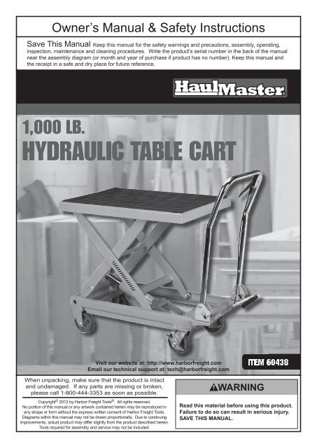
Specifications<br />
SAFETY SETUP<br />
OPERATION MAINTENANCE<br />
Setup - Before Use:<br />
Lift Capacity<br />
Table Height<br />
Table Dimensions<br />
Casters<br />
1,000 lb.<br />
Minimum: 11"<br />
Maximum: 34-1/2"<br />
32" L x 20" W<br />
5" D x 2" W,<br />
(2 swivel with brakes, 2 fixed without brakes)<br />
Read the ENTIRE IMPORTANT SAFETY INFORMATION section at the beginning of this<br />
manual including all text under subheadings therein before set up or use of this product.<br />
Note: For additional information regarding the parts listed in the following pages,<br />
refer to <strong>Parts</strong> <strong>List</strong>s <strong>and</strong> <strong>Diagram</strong>s on page 8.<br />
<strong>Assembly</strong><br />
1. Place the Table <strong>Assembly</strong> on a flat surface which<br />
is well lighted <strong>and</strong> safe for assembly operation.<br />
2. Unfold the H<strong>and</strong>le by pulling it up <strong>and</strong> back into a<br />
vertical position. Lock the H<strong>and</strong>le into position.<br />
Functions<br />
Table<br />
Locking Swivel Caster<br />
H<strong>and</strong>le<br />
Note: The H<strong>and</strong>le may be released <strong>and</strong><br />
folded back down by pressing down the Locking Bar.<br />
Figure A<br />
3. Install the Pump Lever/Foot Pedal assembly into the<br />
Connecting Rod <strong>and</strong> secure in place using the Bolt.<br />
Control Lever<br />
Pump Lever/<br />
Foot Pedal<br />
Locking Bar<br />
Note: The Control Lever controls the operation of the Hydraulic Ram unit.<br />
To lower the Ram <strong>and</strong> Table, squeeze the Control Lever.<br />
When the Control Lever is released, the Ram <strong>and</strong> Table movement will stop <strong>and</strong> the table will remain stationary.<br />
Page 4 For technical questions, please call 1-800-444-3353. Item 60438
Operating Instructions<br />
Read the ENTIRE IMPORTANT SAFETY INFORMATION section at the beginning of this<br />
manual including all text under subheadings therein before set up or use of this product.<br />
Tool Set Up<br />
Bleeding the Hydraulic Ram<br />
Note: Before using this tool, the hydraulic ram<br />
must be purged of air (called bleeding).<br />
Housing<br />
Figure B<br />
Filler Bolt<br />
Workpiece <strong>and</strong> Work Area Set Up<br />
1. Designate a work area that is clean <strong>and</strong> well‐lit.<br />
The work area must not allow access by children<br />
or pets to prevent distraction <strong>and</strong> injury.<br />
1. Remove any load from the Table.<br />
2. Release the Control Lever,<br />
then repeatedly pump the Foot Pedal.<br />
3. When the table has been raised, remove the<br />
Filler Bolt from the Housing. Use a rag to catch<br />
any fluid leaks. Keeping h<strong>and</strong>s <strong>and</strong> tools clear,<br />
squeeze the Control Lever while pumping the<br />
Foot Pedal several times rapidly to lower the Table.<br />
4. Release the Control Lever, <strong>and</strong> pump<br />
more slowly to raise the Table to its full height.<br />
5. Add good quality hydraulic fluid into the opening in<br />
the Housing where the Filler Bolt has been removed.<br />
Fill until the Housing will hold no more fluid.<br />
6. Replace the Filler Bolt <strong>and</strong> its Seal Washer into<br />
the Housing, tighten, but do not overtighten<br />
to avoid damaging the Washer.<br />
7. Check the condition of the Hydraulic Lift Table before<br />
use. Raise <strong>and</strong> lower it several times before adding<br />
any load. Be sure that all controls work properly.<br />
2. Use the Table on a flat, hard, level surface that<br />
is free of debris. Sweep area clean if needed.<br />
SAFETY<br />
MAINTENANCE OPERATION<br />
SETUP<br />
Item 60438<br />
For technical questions, please call 1-800-444-3353.<br />
Page 5
General Operating Instructions<br />
SAFETY SETUP<br />
OPERATION MAINTENANCE<br />
1. Unfold the H<strong>and</strong>le by lifting it up to a<br />
vertical position until it locks in place.<br />
2. Before placing anything on the cart, lock the<br />
back two casters. The Locking Swivel Casters<br />
can be locked by pressing the lever down into<br />
the locked position with your foot. Test the cart<br />
operation using the Foot Pedal <strong>and</strong> Control<br />
Lever. Make sure the Table raises <strong>and</strong> lowers<br />
properly before adding weight to the Table.<br />
3. Observing safe lifting procedures,<br />
move the workpiece onto the cart.<br />
If necessary, secure the item onto the cart using<br />
tie-downs or chocks to keep it stable while moving.<br />
4. Release the Locking Swivel Casters by<br />
moving the levers to the unlock position.<br />
Move the workpiece to the desired location.<br />
5. Before raising the workpiece, lock<br />
the Locking Swivel Casters.<br />
6. To raise the Table, ensure that the Control Lever<br />
is in the released position. Press repeatedly<br />
on the Foot Pedal to raise the table.<br />
7. To lower the Table squeeze the Control Lever.<br />
The Table has a 2-speed valve.<br />
Squeeze the Lever halfway for slowly lowering a load.<br />
Squeeze it fully for quickly lowering<br />
the Table when empty.<br />
8. To prevent accidents, when finished using<br />
the cart, move the cart to a safe location,<br />
lock the Locking Swivel Casters, lower the<br />
Table as far as it will go. Clean, then store<br />
the cart indoors out of children’s reach.<br />
Page 6 For technical questions, please call 1-800-444-3353. Item 60438
Maintenance <strong>and</strong> Servicing<br />
Procedures not specifically explained in this manual must<br />
be performed only by a qualified technician.<br />
TO PREVENT SERIOUS INJURY:<br />
Remove load from Lift Table before service. Lower table when possible before service.<br />
TO PREVENT SERIOUS INJURY FROM TOOL FAILURE:<br />
Do not use damaged equipment. If abnormal noise or vibration<br />
occurs, have the problem corrected before further use.<br />
SAFETY<br />
Cleaning, Maintenance, <strong>and</strong> Lubrication<br />
1. BEFORE EACH USE, inspect the general condition<br />
of the tool. Check for loose hardware, misalignment<br />
or binding of moving parts, cracked or broken<br />
parts, damaged electrical wiring, <strong>and</strong> any other<br />
condition that may affect its safe operation.<br />
2. For convenient storage, the h<strong>and</strong>le can be<br />
folded down. To do this, press down on the<br />
Locking Bar, then press down on the H<strong>and</strong>le.<br />
Note: The Table must be completely lowered<br />
before folding down the H<strong>and</strong>le.<br />
3. For best service, keep your Hydraulic<br />
Cart clean <strong>and</strong> in good condition.<br />
4. Store your Hydraulic cart in a location<br />
where it is protected from moisture, dirt<br />
<strong>and</strong> corrosive atmosphere. Protect it from<br />
being damaged from other items being<br />
moved in <strong>and</strong> out of its storage area.<br />
5. Occasionally apply light grease to the hinge<br />
points of the Scissor Arm <strong>Assembly</strong> <strong>and</strong><br />
other pivot points of the assembly. Wipe off<br />
excess grease, as this will attract dirt.<br />
6. Do not overload this cart, as that may cause damage<br />
to the seals. If the Table will not raise, or slowly<br />
lowers, the cause may be damaged seals or low<br />
hydraulic oil level. To fix this condition, first try the<br />
purging technique discussed on page 5 of this<br />
booklet. If that doesn’t work, take the Hydraulic<br />
Table Cart to a qualified technician for repair.<br />
7. Occasionally check the condition of the wheels.<br />
They should be kept free of grease <strong>and</strong> oil, which<br />
may damage the rubber tires. Occasionally add<br />
grease to the grease fittings on each wheel.<br />
8. AFTER USE, wipe external surfaces<br />
of the tool with clean cloth.<br />
MAINTENANCE OPERATION<br />
SETUP<br />
Item 60438<br />
For technical questions, please call 1-800-444-3353.<br />
Page 7
<strong>Parts</strong> <strong>List</strong>s <strong>and</strong> <strong>Diagram</strong>s<br />
Main <strong>Parts</strong> <strong>List</strong> <strong>and</strong> <strong>Assembly</strong> <strong>Diagram</strong><br />
SAFETY SETUP<br />
OPERATION MAINTENANCE<br />
Part Description Qty<br />
1 H<strong>and</strong>le 1<br />
2 Roll Pin 1<br />
3 Control Lever 1<br />
4 Hex Nut 13<br />
5 Bolt 1<br />
6 Jacket 1<br />
7 Pull Rod 1<br />
8 Retaining Ring 6<br />
9 Pin 1<br />
10 Power Unit 1<br />
11 Pin 1<br />
12 Retaining Ring 2<br />
13 Bushing 2<br />
14 Bushing 1<br />
15 Cushion 1<br />
16 Pump Lever 1<br />
Part Description Qty<br />
17 Cotter Pin 1<br />
18 Pin 1<br />
19 Connecting Rod 1<br />
20 Bolt 13<br />
21 Foot Pedal 1<br />
22 Grip Seat 2<br />
23 Cotter Pin 6<br />
24 Washer 16<br />
25 H<strong>and</strong>le Lock Pivot 2<br />
26 Spring 2<br />
27 Pin 4<br />
28 Locking Bar 1<br />
29 Washer 2<br />
30 Spring Washer 12<br />
31 Locking Swivel Caster 2<br />
32 Base 1<br />
Part Description Qty<br />
33 Lock Nut 2<br />
34 Wheel 2<br />
35 Bushing 2<br />
36 Hex Bolt 2<br />
37 Bearing 4<br />
38 Washer 4<br />
39 Roller 2<br />
40 Washer 4<br />
41 Pin 4<br />
42 Bushing 2<br />
43 Scissor Arm <strong>Assembly</strong> 1<br />
44 Bushing 2<br />
45 Roller 2<br />
46 Protective Mat 1<br />
47 Table 1<br />
Page 8 For technical questions, please call 1-800-444-3353. Item 60438
<strong>Parts</strong> <strong>List</strong> <strong>and</strong> <strong>Assembly</strong> <strong>Diagram</strong> A – Ram<br />
Part Description Qty<br />
1a Dust Ring 1<br />
2a O-ring 1<br />
3a Top Nut 1<br />
4a Sealing Gasket 1<br />
5a Filler Bolt 1<br />
6a Housing 1<br />
7a T-ring 1<br />
8a Cylinder 1<br />
9a Copper Washer 1<br />
10a Ram 1<br />
11a O-ring 1<br />
12a Piston 1<br />
13a O-ring Retainer 1<br />
14a O-ring 1<br />
15a Washer 1<br />
16a Retaining Ring 1<br />
Part Description Qty<br />
17a Base 1<br />
18a Spring 1<br />
19a Release Valve 1<br />
20a Seal Washer 2<br />
21a Axle Sleeve 1<br />
22a O-ring 2<br />
23a Screw 1<br />
24a Nut 3<br />
25a Cotter Pin 2<br />
26a Pin 1<br />
27a Washer 2<br />
28a Bolt 1<br />
29a Seal Washer 1<br />
30a Pump Cylinder 1<br />
31a U-cup 1<br />
32a Dust Ring 1<br />
Part Description Qty<br />
33a Pump Piston 1<br />
34a Pin 1<br />
35a Linkage 2<br />
36a Spring Cap 1<br />
37a Spring 1<br />
38a Bolt 1<br />
39a Plug 1<br />
40a Spring 1<br />
41a Pumping Valve Spindle 1<br />
42a Pumping Valve Seat 1<br />
43a Steel Ball 1<br />
44a Steel Ball 1<br />
45a Ball Seat 1<br />
46a Spring 1<br />
47a O-ring 1<br />
48a Adjusting Bolt 1<br />
SAFETY<br />
1a<br />
2a<br />
10a<br />
8a<br />
3a<br />
11a<br />
4a<br />
5a<br />
9a<br />
12a 13a 14a<br />
15a 16a<br />
18a<br />
19a<br />
20a<br />
21a<br />
22a<br />
23a<br />
6a<br />
17a<br />
25a<br />
24a<br />
26a<br />
7a<br />
28a<br />
27a<br />
48a<br />
47a<br />
46a<br />
45a<br />
44a<br />
42a<br />
24a<br />
24a<br />
29a<br />
30a<br />
31a<br />
38a<br />
20a<br />
40a<br />
41a<br />
43a<br />
32a<br />
33a<br />
38a<br />
37a<br />
36a<br />
34a 35a<br />
25a<br />
MAINTENANCE OPERATION<br />
SETUP<br />
Item 60438<br />
For technical questions, please call 1-800-444-3353.<br />
Page 9
PLEASE READ THE FOLLOWING CAREFULLY<br />
THE MANUFACTURER AND/OR DISTRIBUTOR HAS PROVIDED THE PARTS LIST AND ASSEMBLY DIAGRAM<br />
IN THIS MANUAL AS A REFERENCE TOOL ONLY. NEITHER THE MANUFACTURER OR DISTRIBUTOR<br />
MAKES ANY REPRESENTATION OR WARRANTY OF ANY KIND TO THE BUYER THAT HE OR SHE IS<br />
QUALIFIED TO MAKE ANY REPAIRS TO THE PRODUCT, OR THAT HE OR SHE IS QUALIFIED TO REPLACE<br />
ANY PARTS OF THE PRODUCT. IN FACT, THE MANUFACTURER AND/OR DISTRIBUTOR EXPRESSLY<br />
STATES THAT ALL REPAIRS AND PARTS REPLACEMENTS SHOULD BE UNDERTAKEN BY CERTIFIED AND<br />
LICENSED TECHNICIANS, AND NOT BY THE BUYER. THE BUYER ASSUMES ALL RISK AND LIABILITY<br />
ARISING OUT OF HIS OR HER REPAIRS TO THE ORIGINAL PRODUCT OR REPLACEMENT PARTS<br />
THERETO, OR ARISING OUT OF HIS OR HER INSTALLATION OF REPLACEMENT PARTS THERETO.<br />
Page 10 For technical questions, please call 1-800-444-3353. Item 60438
Record Product’s Serial Number Here:<br />
Note: If product has no serial number, record month <strong>and</strong> year of purchase instead.<br />
Note: Some parts are listed <strong>and</strong> shown for illustration purposes only,<br />
<strong>and</strong> are not available individually as replacement parts.<br />
Item 60438<br />
For technical questions, please call 1-800-444-3353.<br />
Page 11
Limited 90 Day Warranty<br />
<strong>Harbor</strong> <strong>Freight</strong> <strong>Tools</strong> Co. makes every effort to assure that its products meet high quality <strong>and</strong> durability st<strong>and</strong>ards,<br />
<strong>and</strong> warrants to the original purchaser that this product is free from defects in materials <strong>and</strong> workmanship for the<br />
period of 90 days from the date of purchase. This warranty does not apply to damage due directly or indirectly,<br />
to misuse, abuse, negligence or accidents, repairs or alterations outside our facilities, criminal activity, improper<br />
installation, normal wear <strong>and</strong> tear, or to lack of maintenance. We shall in no event be liable for death, injuries<br />
to persons or property, or for incidental, contingent, special or consequential damages arising from the use of<br />
our product. Some states do not allow the exclusion or limitation of incidental or consequential damages, so the<br />
above limitation of exclusion may not apply to you. THIS WARRANTY IS EXPRESSLY IN LIEU OF ALL OTHER<br />
WARRANTIES, EXPRESS OR IMPLIED, INCLUDING THE WARRANTIES OF MERCHANTABILITY AND FITNESS.<br />
To take advantage of this warranty, the product or part must be returned to us with transportation charges<br />
prepaid. Proof of purchase date <strong>and</strong> an explanation of the complaint must accompany the merch<strong>and</strong>ise.<br />
If our inspection verifies the defect, we will either repair or replace the product at our election or we may<br />
elect to refund the purchase price if we cannot readily <strong>and</strong> quickly provide you with a replacement. We will<br />
return repaired products at our expense, but if we determine there is no defect, or that the defect resulted<br />
from causes not within the scope of our warranty, then you must bear the cost of returning the product.<br />
This warranty gives you specific legal rights <strong>and</strong> you may also have other rights which vary from state to state.<br />
3491 Mission Oaks Blvd. • PO Box 6009 • Camarillo, CA 93011 • (800) 444-3353