51 PIECE AIR TOOL KIT - Harbor Freight Tools
51 PIECE AIR TOOL KIT - Harbor Freight Tools
51 PIECE AIR TOOL KIT - Harbor Freight Tools

Create successful ePaper yourself
Turn your PDF publications into a flip-book with our unique Google optimized e-Paper software.
R<br />
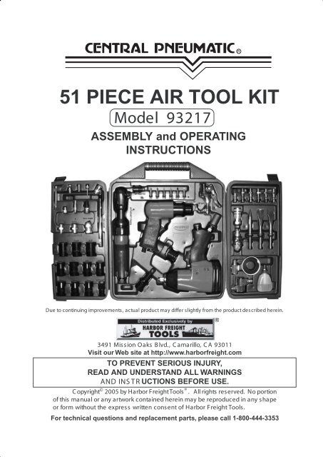
<strong>51</strong> <strong>PIECE</strong> <strong>AIR</strong> <strong>TOOL</strong> <strong>KIT</strong><br />
Model 93217<br />
ASSEMBLY and OPERATING<br />
INSTRUCTIONS<br />
Due to continuing improvements, actual product may differ slightly from the product described herein.<br />
3491 Mission Oaks B lvd., C amarillo, C A 93011<br />
Visit our Web site at http://www.harborfreight.com<br />
TO PREVENT SERIOUS INJURY,<br />
READ AND UNDERSTAND ALL WARNINGS<br />
AND INS TR UCTIONS BEFORE USE.<br />
C opyright © 2005 by <strong>Harbor</strong> <strong>Freight</strong><strong>Tools</strong> ® . All rights reserved. No portion<br />
of this manual or any artwork contained herein may be reproduced in any shape<br />
or form without the express written consent of <strong>Harbor</strong> <strong>Freight</strong> <strong>Tools</strong>.<br />
For technical questions and replacement parts, please call 1-800-444-3353
Description<br />
Qty.<br />
Blowmold C arrying C ase 1<br />
1/2” Drive, 3” E xtension Bar 1<br />
Drive Adapter 3/8” to 1/2” 1<br />
Impact S ocket 5/8”, 3/4”, 11/16”, 1/2”, 9/16” 10<br />
11mm, 12mm, 13mm, 14mm, 17mm<br />
1/4” Hex Driver Bits 6<br />
C hisel 3<br />
C hisel S pring 1<br />
Air R egulator 1<br />
S wivel Hose C onnector 1<br />
Blowgun 1<br />
R ubber Nozzle 1<br />
S afety Nozzle 1<br />
High P ressure Nozzle 1<br />
Tapered Nozzle 1<br />
S KU 93217<br />
Specifications<br />
Air Inlet<br />
1/4”-18 NP T (All tools)<br />
Operating Pressure<br />
90 PS I (All tools)<br />
Air Ratchet Dimensions 10-3/8”L x 2-1/8”H x 1-5/8” Dia.<br />
Drive S ize 3/8” S q.<br />
Maximum Torque Output 50 Ft. Lbs.<br />
Operating R PM’s<br />
150 R PM<br />
Air C onsumption<br />
4 C FM<br />
Air R atchet Weight<br />
2.6 Lbs.<br />
Impact Wrench Dimensions 7-1/8”L x 8”H x 2-3/4”W<br />
Driver S ize 1/2” S q.<br />
Air C onsumption<br />
4 C FM<br />
Operating R P M’s<br />
7,000 R P M<br />
Maximum Torque Output 230 Ft. Lbs.<br />
ImpactWrench Weight 5.0 Lbs.<br />
Air Hammer Dimensions 6-3/4” L x 2” W x 6” H<br />
C huck Diameter 0.403”<br />
Blows P er Minute<br />
4,500 BPM<br />
Air C onsumption<br />
3.4 C FM<br />
Air Hammer Weight<br />
2.4 Lbs.<br />
ACCESSORY LIST<br />
Save This Manual<br />
P age 2<br />
Description<br />
Qty.<br />
Dual Foot Tire Gauge 1<br />
Ball Foot Tire C huck 1<br />
Female Hose C onnector 1<br />
Female Nipple 1<br />
Male Nipple 5<br />
Male Hose C onnector 1<br />
Female Quick C oupler 1<br />
S ports Needle 1<br />
S ports Adapter 1<br />
Air Tool Oiler 1<br />
Bottle of Air Tool Oil 1<br />
R oll of Teflon Tape 1<br />
Hex Bit Adapter 1<br />
Allen Wrench 1<br />
You will need the manual for the safety warnings and precautions, assembly instructions,<br />
operating and maintenance procedures, parts list and diagram. Keep your invoice with this<br />
manual. Write the invoice number on the inside of the front cover. Keep the manual and<br />
invoice in a safe and dry place for future reference.<br />
Safety Warnings and Precautions<br />
WARNING: When using tools, basic safety precautions should always be followed to<br />
reduce the risk of personal injury and damage to equipment.<br />
Read all instructions before using this product!<br />
1. Keep work area clean. C luttered areas invite injuries.<br />
2. Observe work area conditions. Do not use machines or power tools in damp or wet<br />
locations. Don’t expose to rain. K eep work area well lit. Do not use electrically<br />
powered tools in the presence of flammable gases or liquids.
3. Keep children away. Children must never be allowed in the work area. Do not let<br />
them handle machines, tools, extension cords, or air hoses.<br />
4. Store idle equipment. When not in use, tools must be stored in a dry location to<br />
inhibit rust. Always lock up tools and keep out of reach of children.<br />
5. Use the right tool for the job. Do not attempt to force a small tool or attachment to do<br />
the work of a larger industrial tool. There are certain applications for which these tools<br />
were designed. They will do the job better and more safely at the rate for which they<br />
were intended. Do not modify these tools and do not use these tools for a purpose for<br />
which they were not intended.<br />
6. Dress properly. Do not wear loose clothing or jewelry as they can be caught in<br />
moving parts. Protective, electrically non-conductive clothes and non-skid footwear<br />
are recommended when working. Wear restrictive hair covering to contain long hair.<br />
7. Use eye and ear protection. Always wear ANSI approved impact safety goggles.<br />
Wear a full face shield if you are producing metal filings, or flying chips of wood,<br />
concrete, metal or any other material. Wear an ANSI approved dust mask or respirator<br />
when working around metal, wood, and chemical dusts and mists.<br />
8. Do not overreach. Keep proper footing and balance at all times. Do not reach over<br />
or across running machines or air hoses.<br />
9. Maintain tools with care. Keep tools clean for better and safer performance. Follow<br />
instructions for lubricating and changing accessories. Inspect tool cords and air hoses<br />
periodically and, if damaged, have them repaired by an authorized technician. The<br />
handles must be kept clean, dry, and free from oil and grease at all times.<br />
10. Disconnect air supply. Disconnect air hose when not in use.<br />
11. Remove adjusting keys and wrenches. Check that keys and adjusting wrenches<br />
are removed from the tool or machine work surface before connecting the tool.<br />
12. Avoid unintentional starting. Be sure the trigger is released when not in use and<br />
before connecting to the air source. Do not carry any tool with your finger on the<br />
trigger, whether it is connected or not.<br />
13. Stay alert. Watch what you are doing, use common sense. Do not operate any tool<br />
when you are tired.<br />
14. Check for damaged parts. Before using any tool, any part that appears damaged<br />
should be carefully checked to determine that it will operate properly and perform its<br />
intended function. Check for alignment and binding of moving parts; any broken parts<br />
or mounting fixtures; and any other condition that may affect proper operation. Any<br />
part that is damaged should be properly repaired or replaced by a qualified<br />
technician. Do not use the tool if the trigger does not operate properly.<br />
15. Guard against electric shock. Prevent body contact with grounded surfaces such as<br />
pipes, radiators, ranges, and refrigerator enclosures.<br />
16. Replacement parts and accessories. When servicing, use only identical<br />
replacement parts. Use of any other parts will void the warranty. Only use accessories<br />
intended for use with these tools. Approved accessories are available from <strong>Harbor</strong><br />
<strong>Freight</strong> <strong>Tools</strong>.<br />
SKU 93217<br />
Page 3
17. Industrial applications must follow OSHA guidelines.<br />
18. Do not operate tool if under the influence of alcohol or drugs. Read warning labels<br />
if taking prescription medicine to determine if your judgement or reflexes are impaired<br />
while taking drugs. If there is any doubt, do not operate the tool.<br />
19. Use proper size and type extension cord. If an extension cord is required for an air<br />
compressor, it must be of the proper size and type to supply the correct current to the<br />
compressor without heating up. Otherwise, the extension cord could melt and catch<br />
fire, or cause electrical damage to the compressor. Check your air compressor’s<br />
manual for the appropriate size cord.<br />
20. Maintenance. For your safety, maintenance should be performed regularly by a<br />
qualified technician.<br />
21. Compressed air only. Never use combustible gas as a power source.<br />
22. Use both hands. The torque generated from these tools can cause the tools to break<br />
free of your grasp, causing serious injury and damage. Always operate the tools with<br />
both hands.<br />
Note: Performance of the compressor (if powered by line voltage) may vary depending<br />
on variations in local line voltage. Extension cord usage may also affect tool performance.<br />
Warning:The warnings, cautions, and instructions discussed in this instruction manual<br />
cannot cover all possible conditions and situations that may occur. It must be understood<br />
by the operator that common sense and caution are factors which cannot be built into<br />
this product, but must be supplied by the operator.<br />
WARNING: Some dust created by power sanding, sawing, grinding, drilling, and<br />
other construction activities, contain chemicals known [to the State of California]<br />
to cause cancer, birth defects or other reproductive harm. Some examples of<br />
these chemicals are:<br />
- Lead from lead-based paints<br />
- Crystalline silica from bricks and cement or other masonry products<br />
- Arsenic and chromium from chemically treated lumber<br />
Your risk from these exposures varies, depending on how often you do this type<br />
of work. To reduce your exposure to these chemicals: work in a well ventilated<br />
area, and work with approved safety equipment, such as those dust masks that<br />
are specially designed to filter out microscopic particles.<br />
(California Health & Safety Code 25249.5, et seq. )<br />
Unpacking<br />
When unpacking, check to make sure all of the parts listed on pages 10-13 are included.<br />
If any parts are missing or broken, please call <strong>Harbor</strong> <strong>Freight</strong> <strong>Tools</strong> at the number on the cover<br />
of this manual as soon as possible.<br />
SKU 93217<br />
Page 4
Operation<br />
Note: The directions below apply to the Air Impact Wrench, Air Hammer, and Air Ratchet.<br />
1. You will need to prepare a 1/4” air connector to connect to the air inlet on either the Air<br />
Impact Wrench, Air Hammer, or Air Ratchet. First, wrap the 1/4” air connector with pipe<br />
thread seal tape before threading it into the Air Inlet. Connect the 3/8” ID Air Source<br />
Hose to the tool.<br />
Note: If you are not using an automatic oiler system, before operation, add a few drops of<br />
Pneumatic Tool Oil to the airline connection. Add a few drops more after each hour of<br />
continual use.<br />
2. Set the air pressure on your compressor to 90 PSI. Do not exceed the recommended<br />
air pressure of 90 PSI.<br />
3. Check the air connection for leaks. Once you are satisfied there are no leaks, turn off<br />
the air compressor and disconnect the tool.<br />
Air Tool<br />
1/4”-NPT<br />
For best service you should incorporate an oiler, regulator, and inline filter, as shown in<br />
the diagram above. Hoses, couplers, oilers, regulators, and filters are all available at <strong>Harbor</strong><br />
<strong>Freight</strong> <strong>Tools</strong>.<br />
NOTE: The information in the box below refers to all three of the Assembly Drawings<br />
and Parts Lists on pages 10, 11, and 12.<br />
SKU 93217<br />
PLEASE READ THE FOLLOWING CAREFULLY<br />
THE MANUFACTURER AND/OR DISTRIBUTOR HAS PROVIDEDTHE PARTS DIAGRAM INTHIS<br />
MANUAL AS A REFERENCE <strong>TOOL</strong> ONLY. NEITHER THE MANUFACTURER NOR DISTRIBUTOR<br />
MAKES ANY REPRESENTATION OR WARRANTY OF ANY KIND TO THE BUYER THAT HE OR SHE<br />
IS QUALIFIED TO MAKE ANY REP<strong>AIR</strong>S TO THE PRODUCT OR THAT HE OR SHE IS QUALIFIED TO<br />
REPLACE ANY PARTS OFTHE PRODUCT. IN FACT,THE MANUFACTURER AND/OR DISTRIBUTOR<br />
EXPRESSLY STATESTHAT ALL REP<strong>AIR</strong>S AND PARTS REPLACEMENTS SHOULD BE UNDERTAKEN<br />
BY CERTIFIED AND LICENSED TECHNICIANS AND NOT BY THE BUYER. THE BUYER ASSUMES<br />
ALL RISK AND LIABILITY ARISING OUT OF HIS OR HER REP<strong>AIR</strong>S TO THE ORIGINAL PRODUCT<br />
OR REPLACEMENT PARTS THERETO, OR ARISING OUT OF HIS OR HER INSTALLATION OF<br />
REPLACEMENT PARTS THERETO.<br />
Page 5
Air Ratchet Operation<br />
FIGURE 1<br />
Reverse Switch (13)<br />
Air Inlet (1)<br />
Trigger Pivot Area<br />
Throttle Lever (5)<br />
Anvil (15)<br />
Warning! Do not use a “cheater” bar or other extension to increase torque for this tool.<br />
Do not exceed the maximum torque rating on this tool.<br />
Warning! Disconnect the Ratchet from the air source when attaching and removing<br />
sockets. There is no safety lock mechanism on this tool; always disconnect from the<br />
air source when not in use.<br />
Refer to the photograph above.<br />
1. Attach a 3/8” drive socket to the Ratchet Anvil (15).<br />
2. By following the directions on page 5, attach the Ratchet to the air source hose.<br />
3. Gently press the Throttle Lever (5) to activate the Ratchet. Do not force the unit;<br />
allow it to do the work for you. To change direction (loosen vs. tighten), stop the tool<br />
and move it away from the workpiece, then turn the Reverse Switch (13).<br />
4. To adjust the torque, re-adjust the air pressure by changing the setting on the compressor.<br />
Do not exceed the maximum air pressure of 90 PSI for this tool at any time.<br />
5. When you are finished working, turn off the compressor and disconnect the air source<br />
hose.<br />
Warning! There may still be air in the Ratchet. Squeeze the Throttle Lever (5) and activate the<br />
Ratchet to expel any air still inside the tool.<br />
6. Remove the socket.<br />
Maintenance<br />
Warning! Always disconnect the Ratchet from the air source hose before attempting any<br />
maintenance.<br />
1. Wipe the unit down with a lint free cloth.<br />
2. Periodically apply a high grade, light machine oil to the Trigger Pivot area (see above).<br />
3. Make sure the Ratchet Anvil (15), the Air Inlet (01), and the Reverse Switch (13) are<br />
clear of grease, dirt, or debris.<br />
SKU 93217<br />
Page 6
Air Impact Wrench Operation<br />
FIGURE 2<br />
Oil Screw (44)<br />
Air Inlet (10)<br />
Air Regulator (12)<br />
Trigger (4)<br />
Anvil (18)<br />
Forward/Reverse Lever<br />
Warning!! This Impact Wrench supplies powerful torque and is designed to be operated with<br />
two hands. Failure to operate the Impact Wrench with two hands may result in serious injury.<br />
Note: Turn off your air compressor and disconnect the air hose when you are changing sockets.<br />
After you attach the socket, attach the air hose and turn the air compressor on.<br />
1. Select the appropriate size 1/2” impact drive socket for your needs.<br />
2. Push and snap the socket onto the Anvil (18).<br />
Tightening<br />
Note: Slide the Forward/Reverse Lever (3) toward the front of the Wrench.<br />
3. If available, check the recommended torque specification for the nut. To accurately<br />
tighten hardware, use a torque wrench (not included) to tighten the nut to the proper<br />
setting, instead of the impact wrench.<br />
4. Tighten the nut as tight as you can by hand.<br />
5. Place the socket over the nut you wish to tighten.<br />
6. Grip the Impact Wrench firmly with two hands and gently squeeze the Trigger (4).<br />
Note: With the Trigger (4) released, fine tune the air flow with the Air Regulator (12) knob.<br />
Note: If the Impact Wrench cannot tighten the nut to your satisfaction, do not raise the air<br />
pressure on the compressor over 90 PSI. Pressures above 90 PSI will strip the workpiece<br />
and damage the tool. Use other appropriate methods and tools to tighten the nut.<br />
7. When the nut is tightened, release the Trigger (4). Turn off the air compressor and<br />
disconnect the hose.<br />
Loosening<br />
Note: Slide the Forward/Reverse Lever (3) toward the rear of the Wrench.<br />
8. Place the socket over the nut you wish to loosen.<br />
9. Grip the Impact Wrench firmly with two hands and gently squeeze the Trigger (4).<br />
Note: If the Impact Wrench cannot loosen the nut, do not raise the air pressure on the<br />
compressor over 90 PSI. Do not attempt to loosen the nut with the Impact Wrench. Use<br />
other appropriate methods and tools to loosen the nut.<br />
10. When the nut is loosened, release the Trigger (4). Turn off the air compressor and<br />
disconnect the hose.<br />
11. If needed, remove the nut from the socket.<br />
SKU 93217<br />
Page 7
1. Make sure your Impact Wrench is disconnected from the air hose before attempting<br />
any maintenance.<br />
2. If you are not using an automatic oiler system, put a few drops of pneumatic tool oil<br />
through the air line before and after each use. During use, add a few drops every hour.<br />
3. Apply a few drops of oil to the oil entry port before each use. Remove the Screw, add<br />
the oil, then replace the Screw. See FIGURE 2 on page 7.<br />
4. Wipe the Impact Wrench down with a lint free cloth after each use.<br />
5. Make sure the Anvil (18) is clear of dirt and debris. If possible, spray it with compressed<br />
air before each use.<br />
FIGURE 3<br />
Air Impact Wrench Maintenance<br />
Air Hammer Operation<br />
Cylinder (16)<br />
Retainer Spring (17)<br />
Trigger (6)<br />
Chisel<br />
Regulator (5)<br />
Air Inlet (10)<br />
Additional Air Hammer Specific Safety Warnings.<br />
1. Repetitive motions or exposure to vibration may be harmful to your hands and arms.<br />
2. When wearing gloves to operate the Air Hammer, make sure that the gloves do not<br />
interfere with operating the Trigger (6). Test your gloves with the Trigger (6) before attaching<br />
the unit to an air source.<br />
3. Never start the tool unless you have a firm grip with both hands and you are positioned<br />
at your workpiece or area.<br />
4. Before using the Air Hammer, know what is directly underneath the work area or<br />
workpiece. The Air Hammer can quickly penetrate material. If working directly on the<br />
ground, make sure you are not directly above shallow cables, lines, or pipes.<br />
5. Keep your limbs and body clear of the Air Hammer. If a chisel or bit breaks off, the tool<br />
tends to surge forward suddenly. Make sure the immediate area is clear of other people<br />
or animals. Spectators must stay at a safe distance.<br />
6. Never point the tool or the air hose (not included) at anyone.<br />
7. Keep your finger away from the Trigger (6) until you are ready to work.<br />
Warning!! Any spectators in the area will need eye and ear protection.<br />
Beware of flying chips of wood, concrete, metal, or any other material being hammered.<br />
SKU 93217<br />
Page 8
Air Hammer Operation (continued)<br />
Examine your chisels/bits before using them. If a chisel is dull or cracked do not use it.<br />
Replace worn or broken chisels with approved replacement chisels/bits from<br />
<strong>Harbor</strong> <strong>Freight</strong> <strong>Tools</strong>.<br />
Warning!! Always disconnect the tool from the air source<br />
before examining or changing bits.<br />
1. Select the appropriate chisel/bit. Unscrew the Retainer Spring (17) and insert the shank<br />
of the chisel/bit. Screw the Retainer Spring (17) back onto the Cylinder (16).<br />
Holding the Air Chisel firmly, pull the chisel/bit hard to make sure it locked into place.<br />
Note: Before connecting the air supply, make sure you are wearing safety goggles and a full<br />
face mask, ear protection, and steel toe shoes.<br />
Warning!! Any spectators in the immediate area will need eye and ear protection.<br />
Beware of flying chips of wood, concrete, metal, or any other material being chiseled.<br />
2. Connect the air hose to the Air Inlet (11) and turn on the compressor (not included).<br />
3. Grip the Air Hammer with both hands firmly and put the chisel/bit tip up against the<br />
workpiece you wish to chip.<br />
4. Gently squeeze the Trigger (6) and move slowly along the workpiece. Do not push<br />
down on the Air Hammer; let it do the work. If it does not do the intended job to satisfaction,<br />
examine your bit to see if it is worn or dull.<br />
Warning!! Always disconnect from the air source before examining or changing bits.<br />
5. When you are finished, turn off the air supply and then hold the Air Hammer in a safe<br />
direction and Squeeze the trigger to bleed off the remaining air. Then, disconnect the<br />
air hose.<br />
Maintenance<br />
Warning!! Always disconnect from the air source before attempting maintenance.<br />
1. After each use, wipe the Air Hammer down with a lint free cloth.<br />
2. Make sure there are no concrete chips, dirt, or debris in the Retainer Spring (17).<br />
3. Before storage, add a small quantity of high quality pneumatic oil in the Air Inlet (11)<br />
and operate the tool for a couple of seconds to lubricate and protect the internal<br />
mechanism.<br />
4. Examine your chisels/bits before using them. If a chisel is dull or cracked do not use it.<br />
Replace worn or broken chisels with approved replacement chisels from <strong>Harbor</strong> <strong>Freight</strong><br />
<strong>Tools</strong>.<br />
SKU 93217<br />
Page 9
Air Ratchet Assembly Drawing<br />
Part<br />
Part<br />
No. Description Qty No. Description Qty<br />
1 Air Inlet 1 27 Needle Bearing HK1212 1<br />
2 Throttle Spring 1 28 Front End Plate 1<br />
3 Valve Stem 1 29 Ball Bearing (608zz) 1<br />
5 Throttle Lever 1 30 Crank Shaft 1<br />
6 Spring Pin (2.5x22) 1 31 Spring Cap 1<br />
7 O Ring (P8) 1 32 Internal Stop Ring (R29) 1<br />
8 Friction Spring 2 34 Trust Washer 1<br />
9 Pawl 1 35 Throttle Valve 1<br />
10 Steel Ball (4) 2 36 Needle Roller4.5*12.8 1<br />
11 Throttle Handle 1 37 Ratchet Housing 1<br />
12 Throttle Valve Plug 1 38 Clamp Nut 1<br />
13 Reverse Switch 1 39 Ratchet Yoke 1<br />
15 Ratchet Anvil 1 40 Spring Pin (2.5x6) 1<br />
16 Drive Bushing 1 41 Idler Spindle 1<br />
17 Ratchet Spring 1 42 Idler Gear 3<br />
18 Ball Bearing (626zz) 1 43 Needle Roller 4*14.8 3<br />
20 Steel Ball (5) 1 45 Internal Gear 1<br />
21 Rear End Plate 1 46 Exhaust Cover 1<br />
22 Spring Pin (2x6) 1 49 Bushing 1<br />
23 Cylinder 1 50 Bearing Cap 1<br />
24 Rotor 1 53 O-Ring (3x2) 1<br />
25 Rotor Blade 4 56 Washer 1<br />
SKU 93217<br />
Page 10
Air Impact Wrench Assembly Drawing<br />
Part<br />
Part<br />
No. Description Qty No. Description Qty<br />
1 Housing 1 24 Cylinder 1<br />
2 Valve Sleeve 1 25 Rotor 1<br />
3 Forward/Reverse Lever 1 26 Rotor Blade 6<br />
4 Trigger 1 27 Front End Plate 1<br />
5 Pin 3x14 2 28 Ball Bearing 6001ZZ 2<br />
6 Bushing 1 29 Rear End Plate 1<br />
7 Valve Stem 1 30 Pin 3*10 1<br />
8 Steel Ball Ø 10 1 31 Spring 1<br />
9 Spring 1 32 Pin 1<br />
10 Air Inlet 1 33 Rear Gasket 1<br />
12 Air Regulator 1 34 Rear Cover 1<br />
13 O Ring (P6) 1 35 Washer (Ø 5) 4<br />
14 Spring 1 36 Screw M5*15 4<br />
15 O Ring (P7) 1 37 Protecting Rubber 1<br />
16 Screw M5x0.8x8L 1 38 Exhaust Deflector 1<br />
17 Anvil Bushing 1 39 Screw 3*8 2<br />
18 Anvil 1 40 Screw M5*8 1<br />
19 Hammer Cage 1 41 Anvil Collar & Seal 1<br />
20 Hammer Pin 1 42 O Ring 1<br />
21 Hammer Dog 1 43 Rubber 1<br />
22 Drive Cam 1 44 Oil Screw 1<br />
SKU 93217<br />
Page 11
Air Hammer Assembly Drawing<br />
Part<br />
Part<br />
No. Description Qty No. Description Qty<br />
1 Housing 1 10 Spring 1<br />
2 Spring Pin3*14 2 11 Air Inlet 1<br />
3 O-Ring (P9) 2 12 Upper Valve 1<br />
5 Air Regulator 1 13 Valve Disc 1<br />
6 Trigger 1 14 Lower Valve 1<br />
7 O Ring (P3) 1 15 Piston 1<br />
8 Valve Stem 1 16 Cylinder 1<br />
9 Valve 1 17 Retainer Spring 1<br />
SKU 93217<br />
Page 12